EP2565334B1 - Baumaschine mit ölgekühltem Generator - Google Patents
Baumaschine mit ölgekühltem Generator Download PDFInfo
- Publication number
- EP2565334B1 EP2565334B1 EP11007087.7A EP11007087A EP2565334B1 EP 2565334 B1 EP2565334 B1 EP 2565334B1 EP 11007087 A EP11007087 A EP 11007087A EP 2565334 B1 EP2565334 B1 EP 2565334B1
- Authority
- EP
- European Patent Office
- Prior art keywords
- generator
- construction machine
- hydraulic oil
- oil
- hydraulic
- Prior art date
- Legal status (The legal status is an assumption and is not a legal conclusion. Google has not performed a legal analysis and makes no representation as to the accuracy of the status listed.)
- Active
Links
Images

Classifications
-
- E—FIXED CONSTRUCTIONS
- E02—HYDRAULIC ENGINEERING; FOUNDATIONS; SOIL SHIFTING
- E02F—DREDGING; SOIL-SHIFTING
- E02F9/00—Component parts of dredgers or soil-shifting machines, not restricted to one of the kinds covered by groups E02F3/00 - E02F7/00
- E02F9/20—Drives; Control devices
- E02F9/2058—Electric or electro-mechanical or mechanical control devices of vehicle sub-units
- E02F9/2095—Control of electric, electro-mechanical or mechanical equipment not otherwise provided for, e.g. ventilators, electro-driven fans
-
- E—FIXED CONSTRUCTIONS
- E01—CONSTRUCTION OF ROADS, RAILWAYS, OR BRIDGES
- E01C—CONSTRUCTION OF, OR SURFACES FOR, ROADS, SPORTS GROUNDS, OR THE LIKE; MACHINES OR AUXILIARY TOOLS FOR CONSTRUCTION OR REPAIR
- E01C19/00—Machines, tools or auxiliary devices for preparing or distributing paving materials, for working the placed materials, or for forming, consolidating, or finishing the paving
- E01C19/48—Machines, tools or auxiliary devices for preparing or distributing paving materials, for working the placed materials, or for forming, consolidating, or finishing the paving for laying-down the materials and consolidating them, or finishing the surface, e.g. slip forms therefor, forming kerbs or gutters in a continuous operation in situ
-
- E—FIXED CONSTRUCTIONS
- E02—HYDRAULIC ENGINEERING; FOUNDATIONS; SOIL SHIFTING
- E02F—DREDGING; SOIL-SHIFTING
- E02F9/00—Component parts of dredgers or soil-shifting machines, not restricted to one of the kinds covered by groups E02F3/00 - E02F7/00
- E02F9/20—Drives; Control devices
- E02F9/22—Hydraulic or pneumatic drives
- E02F9/226—Safety arrangements, e.g. hydraulic driven fans, preventing cavitation, leakage, overheating
-
- H—ELECTRICITY
- H02—GENERATION; CONVERSION OR DISTRIBUTION OF ELECTRIC POWER
- H02K—DYNAMO-ELECTRIC MACHINES
- H02K5/00—Casings; Enclosures; Supports
- H02K5/04—Casings or enclosures characterised by the shape, form or construction thereof
- H02K5/20—Casings or enclosures characterised by the shape, form or construction thereof with channels or ducts for flow of cooling medium
-
- H—ELECTRICITY
- H02—GENERATION; CONVERSION OR DISTRIBUTION OF ELECTRIC POWER
- H02K—DYNAMO-ELECTRIC MACHINES
- H02K7/00—Arrangements for handling mechanical energy structurally associated with dynamo-electric machines, e.g. structural association with mechanical driving motors or auxiliary dynamo-electric machines
- H02K7/18—Structural association of electric generators with mechanical driving motors, e.g. with turbines
- H02K7/1807—Rotary generators
Definitions
- the present invention relates to a construction machine with an electric generator according to the preamble of claim 1.
- the construction machine may be, for example, a paver or feeder.
- a liquid-cooled generator is for example from the DE 30 28 177 C2 known. It describes a generator with a rotor winding with cooling channels in the conductors. The cooling channels can be flowed through by cooling water.
- Another liquid cooled generator is in the DE 198 54 464 C2 described.
- the generator is arranged in a housing which comprises an annular gap for cooling fluid.
- a disadvantage of the cited prior art is that usually electrically conductive water is used in the vicinity of electrical components.
- the EP 1 199 410 A1 describes a construction machine with a hydraulic pump that is driven by an electric motor, for example, to cool a battery and a generator.
- the generator of the construction machine is driven by an internal combustion engine.
- the JP 2010 168825 A discloses a cooling system for a generator.
- the cooling system includes a pump connected to lines wound around the generator through which cooling fluid is pumped.
- the JP 2010 053596 A describes a construction machine with an internal combustion engine that drives a hydraulic pump via a generator.
- the hydraulic pump is equipped with a piping system, which is intended to cool the generator.
- the DE 10 2007 012 702 A1 describes a method for controlling a generator, whose nominal output voltage is gradually reduced, in order to reduce an actual temperature present at the generator relative to a temperature threshold.
- the EP 2 256 247 A1 discloses a generator of a construction machine sandwiched between an internal combustion engine and a pump transfer case to assure a compact construction.
- the invention has for its object to provide a construction machine with an effectively cooled generator available, wherein means for cooling the generator can be coupled to existing in the construction machine system components, so that the total number of operating components of the construction machine and the total weight can be reduced.
- a construction machine with an electric generator comprises a hydraulic oil system for hydraulic functions, wherein the hydraulic oil system is provided for cooling the generator.
- the hydraulic oil has a lower heat capacity than, for example, water, the oil stores less heat compared to water.
- the advantage of using hydraulic oil is its high boiling point compared to water, whereby no additives must be added.
- Another advantage of the oil is its good electrical insulating property, whereby a leakage does not adversely affect the electric generator. Since the hydraulic oil system is provided independently of the electric generator in the construction machine and fulfills other functions within the construction machine, no separate cooling system for the electric generator is necessary. Furthermore, the heat input into the hydraulic system and thus its temperature is usually lower than in a cooling system for an internal combustion engine.
- the cooling generator comprises a piping system on its outer surface, the piping system being connected to the hydraulic oil system.
- the piping system being connected to the hydraulic oil system.
- the piping system is made of a good thermal conductivity material, preferably steel, stainless steel, aluminum or copper.
- the pipe system according to the invention has a helical shape. Particularly advantageous is a double jacket has been found, for example, a half-pipe coil.
- a pressure limiter is provided in the piping system of the generator in the invention.
- a particularly advantageous variant of the invention provides a control device for the generator, which is configured inter alia to regulate the power of the generator. For example, the power consumption of the generator at high temperatures in or around the generator can be reduced accordingly.
- a further advantageous variant of the invention provides an oil tank, which receives the hydraulic oil from the piping system of the generator, wherein the oil tank is further adapted to receive the hydraulic oil from the hydraulic system.
- the use of a common oil tank saves space, so that the construction machine can be constructed more compact overall.
- a heat exchanger is provided for the cooling of the hydraulic oil of the pipeline system and / or of the hydraulic oil of the hydraulic system.
- the heat exchanger can be used as a pure cooler and deliver the heat of the hydraulic oil to the environment. Further, it would be conceivable that the heat exchanger is connected to a heating system of the construction machine and the heat of the hydraulic system is used for heating other components of the construction machine.
- a device for monitoring the generator wherein the device is ideally designed for interaction with the control device of the generator.
- the device is ideally designed for interaction with the control device of the generator.
- the invention provides that the generator is set up for driving by a combustion engine driven auxiliary drive. Since the internal combustion engine usually represents the primary drive of a construction machine, the generator can thus generate electricity during the entire operation of the construction machine. In addition, the drive of the generator with a PTO disposed between the engine and the generator avoids torque peaks on the generator input shaft and allows the setting of a suitable operating speed for the generator.
- the invention provides a pressure generating oil pump in the piping system, the oil pump being further adapted to cooperate with the hydraulic system.
- a common oil pump can be used for the hydraulic system and the piping system of the generator, whereby an additional component and thus space can be saved.
- the oil pump associated with the engine PTO is provided for driving the oil pump.
- the oil pump generates the oil pressure for the hydraulic system of the construction machine and the piping system of the generator.
- the oil pump is operated directly by the auxiliary drive, wherein optionally a switchable coupling can be provided between the auxiliary drive and the oil pump.
- the drive of the oil pump can be decoupled from the internal combustion engine, which reduces the drag losses on the internal combustion engine.
- a permanent operation of the oil pump can be avoided and rather a situational building up of the oil pressure can be achieved both in the hydraulic system, as well as in the piping system of the generator.
- FIG. 1 shows a construction machine 1 according to the invention in side view, the construction machine 1 here is a paver.
- the construction machine 1 has a structure 2, which receives a control station 3.
- the structure 2 is supported by a chassis 4.
- the chassis 4 transmits driving forces by means of wheels 5 or caterpillars (not shown) on the roadway 6.
- the body 2 has an internal combustion engine 7 as a primary drive source, which is a diesel engine in this example.
- a screed 8 is mounted with a heater 8a.
- a power take-off 9 in this embodiment, a pump distributor gear, connected.
- the drive shaft of an electric generator 10 via a belt drive 11, a propeller shaft or directly connected to the power take-off to generate a voltage for high-performance load of the construction machine 1, for example, the heater 8a of the screed 8.
- the operating voltage generated by the generator 10 is about 400 V.
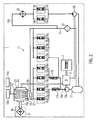
- FIG. 2 schematically represents the construction machine 1 according to the invention with the electric generator 10.
- the generator 10 is connected to electric power lines 10a to powerful consumers, for example, the heater 8a of the screed 8.
- the heater 8a is for heating an asphalt mix.
- the electrical power consumption of the heater 8a is mainly on the width of the screed 8 and optional, additionally connected consumers.
- the generator 10 has a control device 10b and a monitoring device 10c.
- the construction machine 1 further has a hydraulic system 11, which performs various hydraulic functions for the construction machine 1, for example, the adjustment of actuators.
- the at least two different circuits comprehensive hydraulic system 11 has a common for both circuits oil tank 12, which serves as a memory for hydraulic fluid.
- the hydraulic fluid in this example is a hydraulic oil because it has good lubricating properties and viscosity.
- the hydraulic oil is conveyed from the oil tank 12 by two pumps 13a, 13b connected to the oil tank 12, one of which is provided for each of the two different circuits of the hydraulic system 11.
- the hydraulic pumps 13a, 13b generate a continuous volume flow and have a design suitable for this task.
- the drive of the pumps 13a, 13b takes place in each case directly by the auxiliary drive 9. That is to say that the pumps 13a, 13b can permanently convey hydraulic oil from the oil tank 12 during operation of the internal combustion engine 7 and thus generate a largely constant pressure in the hydraulic system 11.
- the hydraulic system 11 further has two flow control valves 17a, 17b, which regulate the oil flow constant to a definable value between 4 and 10 liters per minute, but preferably about 8 liters per minute.
- the hydraulic system 11 performs various hydraulic functions for the construction machine 1.
- the hydraulic system 11 comprises hydraulic working components 18a to 18i connected thereto, e.g. Adjusting cylinder for the screed 8 or the chassis.
- Each working component 18a to 18i in each case comprises an electrically actuable valve 19a to 19i.
- the working components 18a to 18g are arranged in the circuit of the line system 16a and the working components 18h, 18i in the circuit of the line system 16b.
- the working components 18a to 18g require a constant volume flow, for which reason the two flow control valves 17a, 17b are arranged in the line system 16a between the pump 13a and the working components 18a to 18g.
- the working components 18h, 18i do not require a constant volume flow, so that between the pump 13b and the working components 18h, 18i no flow control valve is necessary.
- a return line 21 with a filter 22 connects the returns of the pipe systems 16 a, 16 b with the oil tank 12.
- the generator 10 has a helical pipe system 23, which is cast in a housing 24 of the generator 10, preferably in the form of a double jacket.
- the pipeline system 23 is connected to a hydraulic connection 25 to the flow of the hydraulic line 16 a of the hydraulic system 11.
- a further hydraulic port 26 is provided, which is connected to the return of the hydraulic line 16a. This is connected as a return to the oil tank 12, so that the hydraulic oil flows back into the oil tank 12.
- a pressure limiter 27 is provided.
- the pressure limiter 27 is a pressure relief valve, comprising a bypass with a check valve.
- the cooling of the electric generator 10 within the construction machine 1 can proceed as described below.
- the hydraulic system 11 In the construction machine 1, it may be necessary at the beginning of a labor input that the hydraulic system 11 is rapidly brought to an operating temperature. For example, the hydraulic oil only reaches an ideal viscosity for most components of the hydraulic system 11 at about 70 ° C.
- the cast in the housing 24 of the generator 10, helical pipe system 23 acts in this operating state of the construction machine 1 supportive to the hydraulic system 11, since it additionally heats the hydraulic oil with the heat generated by the generator 10.
- the hydraulic oil is delivered by the pump 13a both by the hydraulic system 11 and by the helical pipeline system 23 of the generator 10 in a substantially constant amount.
- the cooler 20 arranged in the return line of the piping system 16b allows heat to be released from the hydraulic oil to the environment, so that the temperature of the hydraulic oil in the piping system 16b is lowered.
- the controller 10b may limit the power consumption of the generator 10, whereby the generator 10 generates less self-heat.
- a not belonging to the invention construction machine 1 with electric generator 10 can be modified in many ways.
- the pumps 13a, 13b could be driven by an electric motor arranged separately in the construction machine 1.
- the oil pumps 13a, 13b would be driven as needed, and not permanently promote oil through the hydraulic system 11 and the piping system 23 of the generator 10. This would allow a particularly advantageous combination with an engine start-stop system.
- the helical pipeline system 23 of the generator 10 is connected to a further preheating circuit (not shown) in order to heat the generator 10 more quickly to a suitable operating temperature in cold outside temperatures.
Landscapes
- Engineering & Computer Science (AREA)
- Civil Engineering (AREA)
- Structural Engineering (AREA)
- Mining & Mineral Resources (AREA)
- General Engineering & Computer Science (AREA)
- Architecture (AREA)
- Power Engineering (AREA)
- Road Paving Machines (AREA)
- Connection Of Motors, Electrical Generators, Mechanical Devices, And The Like (AREA)
- Fluid-Pressure Circuits (AREA)
- Component Parts Of Construction Machinery (AREA)
Priority Applications (5)
| Application Number | Priority Date | Filing Date | Title |
|---|---|---|---|
| EP11007087.7A EP2565334B1 (de) | 2011-08-31 | 2011-08-31 | Baumaschine mit ölgekühltem Generator |
| PL11007087T PL2565334T3 (pl) | 2011-08-31 | 2011-08-31 | Maszyna budowlana z prądnicą chłodzoną olejem |
| US13/597,796 US9722473B2 (en) | 2011-08-31 | 2012-08-29 | Construction machine with oil-cooled generator |
| JP2012188558A JP6222538B2 (ja) | 2011-08-31 | 2012-08-29 | 油冷式発電機を有する建設機械 |
| CN201210320549.XA CN102966024B (zh) | 2011-08-31 | 2012-08-31 | 具有油冷发电机的建筑机械 |
Applications Claiming Priority (1)
| Application Number | Priority Date | Filing Date | Title |
|---|---|---|---|
| EP11007087.7A EP2565334B1 (de) | 2011-08-31 | 2011-08-31 | Baumaschine mit ölgekühltem Generator |
Publications (2)
| Publication Number | Publication Date |
|---|---|
| EP2565334A1 EP2565334A1 (de) | 2013-03-06 |
| EP2565334B1 true EP2565334B1 (de) | 2016-10-05 |
Family
ID=44581991
Family Applications (1)
| Application Number | Title | Priority Date | Filing Date |
|---|---|---|---|
| EP11007087.7A Active EP2565334B1 (de) | 2011-08-31 | 2011-08-31 | Baumaschine mit ölgekühltem Generator |
Country Status (5)
| Country | Link |
|---|---|
| US (1) | US9722473B2 (pl) |
| EP (1) | EP2565334B1 (pl) |
| JP (1) | JP6222538B2 (pl) |
| CN (1) | CN102966024B (pl) |
| PL (1) | PL2565334T3 (pl) |
Families Citing this family (7)
| Publication number | Priority date | Publication date | Assignee | Title |
|---|---|---|---|---|
| DE102013008032B4 (de) * | 2013-05-13 | 2023-12-21 | Dynapac Gmbh | Verfahren und Vorrichtung zum elektrischen Beheizen einer Fertigerbohle |
| US9711473B1 (en) * | 2016-02-26 | 2017-07-18 | Advanced Semiconductor Engineering, Inc. | Semiconductor die, semiconductor wafer and method for manufacturing the same |
| DE102016009086A1 (de) * | 2016-07-26 | 2018-02-01 | Bomag Gmbh | Handgeführte Bodenverdichtungsmaschine, insbesondere Vibrationsstampfer oder Vibrationsplatte |
| US12024860B2 (en) * | 2021-02-18 | 2024-07-02 | Deere & Company | Preheating intelligence for electric-hydraulic work vehicles |
| CN114351540B (zh) * | 2022-01-19 | 2023-06-30 | 南京欣三人行网络科技有限公司 | 一种具有热能转化为电能的沥青摊铺机 |
| JP2025030692A (ja) * | 2023-08-24 | 2025-03-07 | 株式会社クボタ | 作業機 |
| US20250075447A1 (en) * | 2023-08-28 | 2025-03-06 | Deere & Company | Paver work machine with a thermal management system |
Citations (1)
| Publication number | Priority date | Publication date | Assignee | Title |
|---|---|---|---|---|
| EP2256247A1 (de) * | 2009-05-25 | 2010-12-01 | Joseph Vögele AG | Sraßenfertiger |
Family Cites Families (18)
| Publication number | Priority date | Publication date | Assignee | Title |
|---|---|---|---|---|
| JPS5556467U (pl) * | 1978-10-09 | 1980-04-16 | ||
| DE3028177C2 (de) | 1980-07-25 | 1986-08-14 | Brown, Boveri & Cie Ag, 6800 Mannheim | Flüssigkeitsgekühlter Generator |
| US4516044A (en) * | 1984-05-31 | 1985-05-07 | Cincinnati Milacron Inc. | Heat exchange apparatus for electric motor and electric motor equipped therewith |
| DE19750379B4 (de) | 1997-07-30 | 2007-12-13 | Linde Material Handling Gmbh | Baueinheit mit einem elektrischen Generator und einem Pumpenaggregat |
| DE19854464C2 (de) | 1998-06-20 | 2000-05-18 | Daimler Chrysler Ag | Flüssigkeitsgekühlter Generator |
| JP2001016827A (ja) | 1999-06-30 | 2001-01-19 | Kobelco Contstruction Machinery Ltd | 建設機械 |
| DE20001039U1 (de) | 2000-01-21 | 2000-03-30 | Joseph Voegele Ag, 68163 Mannheim | Straßenfertiger |
| CN2433295Y (zh) * | 2000-07-11 | 2001-06-06 | 三一重工股份有限公司 | 振动轮的循环润滑冷却结构 |
| JP4179465B2 (ja) * | 2002-07-31 | 2008-11-12 | 株式会社小松製作所 | 建設機械 |
| DE102007012702A1 (de) * | 2007-01-29 | 2008-07-31 | Robert Bosch Gmbh | Verfahren zur Regelung eines Generators und Generatorregler |
| US20090102298A1 (en) * | 2007-10-19 | 2009-04-23 | Caterpillar Inc. | Cooling housing for an electric device |
| JP4883058B2 (ja) * | 2008-08-28 | 2012-02-22 | ダイキン工業株式会社 | 建設機械 |
| JP5674086B2 (ja) | 2008-11-10 | 2015-02-25 | 住友重機械工業株式会社 | ハイブリッド型建設機械 |
| JP5421074B2 (ja) * | 2008-11-10 | 2014-02-19 | 住友重機械工業株式会社 | ハイブリッド型建設機械 |
| JP5396882B2 (ja) * | 2009-01-23 | 2014-01-22 | コベルコ建機株式会社 | ハイブリッド作業機械の電動機冷却装置 |
| JP2012526930A (ja) * | 2009-05-12 | 2012-11-01 | エル−フォレスト アクチエボラグ | ハイブリッド車のためのエネルギーシステム |
| US8739906B2 (en) * | 2009-06-19 | 2014-06-03 | Sumitomo Heavy Industries, Ltd. | Hybrid-type construction machine and control method for hybrid-type construction machine |
| CN201581331U (zh) * | 2009-11-27 | 2010-09-15 | 徐州凯莫尔重工科技有限公司 | 摊铺机冷却系统 |
-
2011
- 2011-08-31 PL PL11007087T patent/PL2565334T3/pl unknown
- 2011-08-31 EP EP11007087.7A patent/EP2565334B1/de active Active
-
2012
- 2012-08-29 US US13/597,796 patent/US9722473B2/en active Active
- 2012-08-29 JP JP2012188558A patent/JP6222538B2/ja active Active
- 2012-08-31 CN CN201210320549.XA patent/CN102966024B/zh active Active
Patent Citations (1)
| Publication number | Priority date | Publication date | Assignee | Title |
|---|---|---|---|---|
| EP2256247A1 (de) * | 2009-05-25 | 2010-12-01 | Joseph Vögele AG | Sraßenfertiger |
Also Published As
| Publication number | Publication date |
|---|---|
| EP2565334A1 (de) | 2013-03-06 |
| JP2013053512A (ja) | 2013-03-21 |
| US20130051912A1 (en) | 2013-02-28 |
| JP6222538B2 (ja) | 2017-11-01 |
| CN102966024A (zh) | 2013-03-13 |
| PL2565334T3 (pl) | 2017-07-31 |
| CN102966024B (zh) | 2016-01-20 |
| US9722473B2 (en) | 2017-08-01 |
Similar Documents
| Publication | Publication Date | Title |
|---|---|---|
| EP2565334B1 (de) | Baumaschine mit ölgekühltem Generator | |
| DE102013019687B3 (de) | Kühlsystem für ein Hybridfahrzeug aufweisend zumindest eine elektrische Antriebsmaschine und zumindest eine Verbrennungskraftmaschine und Verfahren zu dessen Regelung | |
| DE102013226804B4 (de) | Antriebsanordnung mit integrierter Schmierung | |
| EP1108572B1 (de) | Wärmetauschsystem für die Heizung eines Fahrzeugs mit Hybridantrieb | |
| EP2559879B1 (de) | Antriebseinheit mit zwei koppelbaren Kühlkreisläufen zum Vorwärmen eines Verbrennungsmotors und Verfahren | |
| DE102011078088A1 (de) | Kühlsystem | |
| DE10318744B4 (de) | Kühlsystem | |
| DE102015007235A1 (de) | Arbeitsmaschine, insbesondere Muldenkipper oder Truck | |
| DE102011115279A1 (de) | Antriebsanordnung für ein Kraftfahrzeug und Verfahren zum Betreiben einer Antriebsanordnung | |
| DE102012200391A1 (de) | Kühlmittelkreislauf für eine Brennkraftmaschine | |
| DE102013015207B4 (de) | Kühlsystem für ein Hybridfahrzeug aufweisend zumindest eine elektrische Antriebsmaschine und zumindest eine Verbrennungskraftmaschine und Verfahren zu dessen Regelung | |
| EP0931209B1 (de) | Antriebseinheit mit thermisch geregelter wasserpumpe | |
| EP2770170B1 (de) | Abwärmenutzungssystem, insbesondere für ein Kraftfahrzeug, mit einer Speisepumpe | |
| EP2647106A2 (de) | Flüssigkeitsfördereinrichtung | |
| EP3405660B1 (de) | Nachlaufkühlsystem, zylinderkopf sowie verfahren zum betrieb eines nachlaufkühlsystems | |
| EP2108813B1 (de) | Vorrichtung zum Kühlen oder Erwärmen eines Verbrennungsmotors | |
| DE102012025436A1 (de) | Verbrennungskraftmaschine | |
| DE102004018227A1 (de) | Kühlsystem | |
| DE102009058131B4 (de) | Vorrichtung | |
| DE102009000777A1 (de) | Verfahren und Einrichtung zur Verbesserung des Wirkungsgrades von Getrieben in Landwirtschaftsfahrzeugen | |
| DE102009052376A1 (de) | Schmiermittelversorgungseinrichtung für einen Kraftwagen | |
| EP0664381B1 (de) | Brennkraftmaschine mit einem Kühlmittelkreislauf | |
| EP1881586B1 (de) | Kühlsystem insbesondere für ein Fahrzeug | |
| DE102009043787A1 (de) | Heizeinrichtung zur Vorwärmung eines Verbrennungsmotors sowie Fahrzeug mit einem Verbrennungsmotor und einer Heizeinrichtung zur Vorwärmung des Verbrennungsmotors | |
| DE10211060B4 (de) | Verfahren und Vorrichtung zur Regelung des Kühlmittelvolumenstromes in einer Brennkraftmaschine |
Legal Events
| Date | Code | Title | Description |
|---|---|---|---|
| PUAI | Public reference made under article 153(3) epc to a published international application that has entered the european phase |
Free format text: ORIGINAL CODE: 0009012 |
|
| 17P | Request for examination filed |
Effective date: 20120727 |
|
| AK | Designated contracting states |
Kind code of ref document: A1 Designated state(s): AL AT BE BG CH CY CZ DE DK EE ES FI FR GB GR HR HU IE IS IT LI LT LU LV MC MK MT NL NO PL PT RO RS SE SI SK SM TR |
|
| AX | Request for extension of the european patent |
Extension state: BA ME |
|
| GRAP | Despatch of communication of intention to grant a patent |
Free format text: ORIGINAL CODE: EPIDOSNIGR1 |
|
| INTG | Intention to grant announced |
Effective date: 20160331 |
|
| GRAS | Grant fee paid |
Free format text: ORIGINAL CODE: EPIDOSNIGR3 |
|
| GRAA | (expected) grant |
Free format text: ORIGINAL CODE: 0009210 |
|
| AK | Designated contracting states |
Kind code of ref document: B1 Designated state(s): AL AT BE BG CH CY CZ DE DK EE ES FI FR GB GR HR HU IE IS IT LI LT LU LV MC MK MT NL NO PL PT RO RS SE SI SK SM TR |
|
| REG | Reference to a national code |
Ref country code: GB Ref legal event code: FG4D Free format text: NOT ENGLISH |
|
| REG | Reference to a national code |
Ref country code: CH Ref legal event code: EP |
|
| REG | Reference to a national code |
Ref country code: AT Ref legal event code: REF Ref document number: 834807 Country of ref document: AT Kind code of ref document: T Effective date: 20161015 |
|
| REG | Reference to a national code |
Ref country code: IE Ref legal event code: FG4D Free format text: LANGUAGE OF EP DOCUMENT: GERMAN |
|
| REG | Reference to a national code |
Ref country code: DE Ref legal event code: R096 Ref document number: 502011010816 Country of ref document: DE |
|
| REG | Reference to a national code |
Ref country code: NL Ref legal event code: MP Effective date: 20161005 |
|
| REG | Reference to a national code |
Ref country code: LT Ref legal event code: MG4D |
|
| PG25 | Lapsed in a contracting state [announced via postgrant information from national office to epo] |
Ref country code: LV Free format text: LAPSE BECAUSE OF FAILURE TO SUBMIT A TRANSLATION OF THE DESCRIPTION OR TO PAY THE FEE WITHIN THE PRESCRIBED TIME-LIMIT Effective date: 20161005 |
|
| PG25 | Lapsed in a contracting state [announced via postgrant information from national office to epo] |
Ref country code: GR Free format text: LAPSE BECAUSE OF FAILURE TO SUBMIT A TRANSLATION OF THE DESCRIPTION OR TO PAY THE FEE WITHIN THE PRESCRIBED TIME-LIMIT Effective date: 20170106 Ref country code: LT Free format text: LAPSE BECAUSE OF FAILURE TO SUBMIT A TRANSLATION OF THE DESCRIPTION OR TO PAY THE FEE WITHIN THE PRESCRIBED TIME-LIMIT Effective date: 20161005 Ref country code: NO Free format text: LAPSE BECAUSE OF FAILURE TO SUBMIT A TRANSLATION OF THE DESCRIPTION OR TO PAY THE FEE WITHIN THE PRESCRIBED TIME-LIMIT Effective date: 20170105 Ref country code: SE Free format text: LAPSE BECAUSE OF FAILURE TO SUBMIT A TRANSLATION OF THE DESCRIPTION OR TO PAY THE FEE WITHIN THE PRESCRIBED TIME-LIMIT Effective date: 20161005 |
|
| PG25 | Lapsed in a contracting state [announced via postgrant information from national office to epo] |
Ref country code: IS Free format text: LAPSE BECAUSE OF FAILURE TO SUBMIT A TRANSLATION OF THE DESCRIPTION OR TO PAY THE FEE WITHIN THE PRESCRIBED TIME-LIMIT Effective date: 20170205 Ref country code: ES Free format text: LAPSE BECAUSE OF FAILURE TO SUBMIT A TRANSLATION OF THE DESCRIPTION OR TO PAY THE FEE WITHIN THE PRESCRIBED TIME-LIMIT Effective date: 20161005 Ref country code: NL Free format text: LAPSE BECAUSE OF FAILURE TO SUBMIT A TRANSLATION OF THE DESCRIPTION OR TO PAY THE FEE WITHIN THE PRESCRIBED TIME-LIMIT Effective date: 20161005 Ref country code: FI Free format text: LAPSE BECAUSE OF FAILURE TO SUBMIT A TRANSLATION OF THE DESCRIPTION OR TO PAY THE FEE WITHIN THE PRESCRIBED TIME-LIMIT Effective date: 20161005 Ref country code: PT Free format text: LAPSE BECAUSE OF FAILURE TO SUBMIT A TRANSLATION OF THE DESCRIPTION OR TO PAY THE FEE WITHIN THE PRESCRIBED TIME-LIMIT Effective date: 20170206 Ref country code: RS Free format text: LAPSE BECAUSE OF FAILURE TO SUBMIT A TRANSLATION OF THE DESCRIPTION OR TO PAY THE FEE WITHIN THE PRESCRIBED TIME-LIMIT Effective date: 20161005 Ref country code: HR Free format text: LAPSE BECAUSE OF FAILURE TO SUBMIT A TRANSLATION OF THE DESCRIPTION OR TO PAY THE FEE WITHIN THE PRESCRIBED TIME-LIMIT Effective date: 20161005 |
|
| REG | Reference to a national code |
Ref country code: DE Ref legal event code: R097 Ref document number: 502011010816 Country of ref document: DE |
|
| PG25 | Lapsed in a contracting state [announced via postgrant information from national office to epo] |
Ref country code: CZ Free format text: LAPSE BECAUSE OF FAILURE TO SUBMIT A TRANSLATION OF THE DESCRIPTION OR TO PAY THE FEE WITHIN THE PRESCRIBED TIME-LIMIT Effective date: 20161005 Ref country code: EE Free format text: LAPSE BECAUSE OF FAILURE TO SUBMIT A TRANSLATION OF THE DESCRIPTION OR TO PAY THE FEE WITHIN THE PRESCRIBED TIME-LIMIT Effective date: 20161005 Ref country code: SK Free format text: LAPSE BECAUSE OF FAILURE TO SUBMIT A TRANSLATION OF THE DESCRIPTION OR TO PAY THE FEE WITHIN THE PRESCRIBED TIME-LIMIT Effective date: 20161005 Ref country code: DK Free format text: LAPSE BECAUSE OF FAILURE TO SUBMIT A TRANSLATION OF THE DESCRIPTION OR TO PAY THE FEE WITHIN THE PRESCRIBED TIME-LIMIT Effective date: 20161005 Ref country code: RO Free format text: LAPSE BECAUSE OF FAILURE TO SUBMIT A TRANSLATION OF THE DESCRIPTION OR TO PAY THE FEE WITHIN THE PRESCRIBED TIME-LIMIT Effective date: 20161005 |
|
| PLBE | No opposition filed within time limit |
Free format text: ORIGINAL CODE: 0009261 |
|
| STAA | Information on the status of an ep patent application or granted ep patent |
Free format text: STATUS: NO OPPOSITION FILED WITHIN TIME LIMIT |
|
| REG | Reference to a national code |
Ref country code: FR Ref legal event code: PLFP Year of fee payment: 7 |
|
| PG25 | Lapsed in a contracting state [announced via postgrant information from national office to epo] |
Ref country code: BG Free format text: LAPSE BECAUSE OF FAILURE TO SUBMIT A TRANSLATION OF THE DESCRIPTION OR TO PAY THE FEE WITHIN THE PRESCRIBED TIME-LIMIT Effective date: 20170105 Ref country code: SM Free format text: LAPSE BECAUSE OF FAILURE TO SUBMIT A TRANSLATION OF THE DESCRIPTION OR TO PAY THE FEE WITHIN THE PRESCRIBED TIME-LIMIT Effective date: 20161005 |
|
| 26N | No opposition filed |
Effective date: 20170706 |
|
| PG25 | Lapsed in a contracting state [announced via postgrant information from national office to epo] |
Ref country code: SI Free format text: LAPSE BECAUSE OF FAILURE TO SUBMIT A TRANSLATION OF THE DESCRIPTION OR TO PAY THE FEE WITHIN THE PRESCRIBED TIME-LIMIT Effective date: 20161005 |
|
| REG | Reference to a national code |
Ref country code: CH Ref legal event code: PL |
|
| PG25 | Lapsed in a contracting state [announced via postgrant information from national office to epo] |
Ref country code: MC Free format text: LAPSE BECAUSE OF FAILURE TO SUBMIT A TRANSLATION OF THE DESCRIPTION OR TO PAY THE FEE WITHIN THE PRESCRIBED TIME-LIMIT Effective date: 20161005 |
|
| PG25 | Lapsed in a contracting state [announced via postgrant information from national office to epo] |
Ref country code: LI Free format text: LAPSE BECAUSE OF NON-PAYMENT OF DUE FEES Effective date: 20170831 Ref country code: CH Free format text: LAPSE BECAUSE OF NON-PAYMENT OF DUE FEES Effective date: 20170831 |
|
| REG | Reference to a national code |
Ref country code: IE Ref legal event code: MM4A |
|
| REG | Reference to a national code |
Ref country code: BE Ref legal event code: MM Effective date: 20170831 |
|
| PG25 | Lapsed in a contracting state [announced via postgrant information from national office to epo] |
Ref country code: LU Free format text: LAPSE BECAUSE OF NON-PAYMENT OF DUE FEES Effective date: 20170831 |
|
| PG25 | Lapsed in a contracting state [announced via postgrant information from national office to epo] |
Ref country code: IE Free format text: LAPSE BECAUSE OF NON-PAYMENT OF DUE FEES Effective date: 20170831 |
|
| REG | Reference to a national code |
Ref country code: FR Ref legal event code: PLFP Year of fee payment: 8 |
|
| PG25 | Lapsed in a contracting state [announced via postgrant information from national office to epo] |
Ref country code: BE Free format text: LAPSE BECAUSE OF NON-PAYMENT OF DUE FEES Effective date: 20170831 |
|
| PG25 | Lapsed in a contracting state [announced via postgrant information from national office to epo] |
Ref country code: MT Free format text: LAPSE BECAUSE OF FAILURE TO SUBMIT A TRANSLATION OF THE DESCRIPTION OR TO PAY THE FEE WITHIN THE PRESCRIBED TIME-LIMIT Effective date: 20161005 |
|
| REG | Reference to a national code |
Ref country code: AT Ref legal event code: MM01 Ref document number: 834807 Country of ref document: AT Kind code of ref document: T Effective date: 20170831 |
|
| PG25 | Lapsed in a contracting state [announced via postgrant information from national office to epo] |
Ref country code: AT Free format text: LAPSE BECAUSE OF NON-PAYMENT OF DUE FEES Effective date: 20170831 |
|
| PG25 | Lapsed in a contracting state [announced via postgrant information from national office to epo] |
Ref country code: HU Free format text: LAPSE BECAUSE OF FAILURE TO SUBMIT A TRANSLATION OF THE DESCRIPTION OR TO PAY THE FEE WITHIN THE PRESCRIBED TIME-LIMIT; INVALID AB INITIO Effective date: 20110831 |
|
| PG25 | Lapsed in a contracting state [announced via postgrant information from national office to epo] |
Ref country code: CY Free format text: LAPSE BECAUSE OF NON-PAYMENT OF DUE FEES Effective date: 20161005 |
|
| PG25 | Lapsed in a contracting state [announced via postgrant information from national office to epo] |
Ref country code: MK Free format text: LAPSE BECAUSE OF FAILURE TO SUBMIT A TRANSLATION OF THE DESCRIPTION OR TO PAY THE FEE WITHIN THE PRESCRIBED TIME-LIMIT Effective date: 20161005 |
|
| PG25 | Lapsed in a contracting state [announced via postgrant information from national office to epo] |
Ref country code: TR Free format text: LAPSE BECAUSE OF FAILURE TO SUBMIT A TRANSLATION OF THE DESCRIPTION OR TO PAY THE FEE WITHIN THE PRESCRIBED TIME-LIMIT Effective date: 20161005 |
|
| PG25 | Lapsed in a contracting state [announced via postgrant information from national office to epo] |
Ref country code: AL Free format text: LAPSE BECAUSE OF FAILURE TO SUBMIT A TRANSLATION OF THE DESCRIPTION OR TO PAY THE FEE WITHIN THE PRESCRIBED TIME-LIMIT Effective date: 20161005 |
|
| P01 | Opt-out of the competence of the unified patent court (upc) registered |
Effective date: 20230524 |
|
| PGFP | Annual fee paid to national office [announced via postgrant information from national office to epo] |
Ref country code: DE Payment date: 20250828 Year of fee payment: 15 |
|
| PGFP | Annual fee paid to national office [announced via postgrant information from national office to epo] |
Ref country code: PL Payment date: 20250821 Year of fee payment: 15 Ref country code: IT Payment date: 20250827 Year of fee payment: 15 |
|
| PGFP | Annual fee paid to national office [announced via postgrant information from national office to epo] |
Ref country code: GB Payment date: 20250827 Year of fee payment: 15 |
|
| PGFP | Annual fee paid to national office [announced via postgrant information from national office to epo] |
Ref country code: FR Payment date: 20250826 Year of fee payment: 15 |