EP2565334B1 - Construction machine with oil-cooled generator - Google Patents
Construction machine with oil-cooled generator Download PDFInfo
- Publication number
- EP2565334B1 EP2565334B1 EP11007087.7A EP11007087A EP2565334B1 EP 2565334 B1 EP2565334 B1 EP 2565334B1 EP 11007087 A EP11007087 A EP 11007087A EP 2565334 B1 EP2565334 B1 EP 2565334B1
- Authority
- EP
- European Patent Office
- Prior art keywords
- generator
- construction machine
- hydraulic oil
- oil
- hydraulic
- Prior art date
- Legal status (The legal status is an assumption and is not a legal conclusion. Google has not performed a legal analysis and makes no representation as to the accuracy of the status listed.)
- Active
Links
- 238000010276 construction Methods 0.000 title claims description 49
- 239000010720 hydraulic oil Substances 0.000 claims description 40
- 239000003921 oil Substances 0.000 claims description 38
- 238000001816 cooling Methods 0.000 claims description 24
- 238000002485 combustion reaction Methods 0.000 claims description 16
- 230000006870 function Effects 0.000 claims description 6
- 238000010438 heat treatment Methods 0.000 claims description 6
- RYGMFSIKBFXOCR-UHFFFAOYSA-N Copper Chemical compound [Cu] RYGMFSIKBFXOCR-UHFFFAOYSA-N 0.000 claims description 2
- 229910000831 Steel Inorganic materials 0.000 claims description 2
- XAGFODPZIPBFFR-UHFFFAOYSA-N aluminium Chemical compound [Al] XAGFODPZIPBFFR-UHFFFAOYSA-N 0.000 claims description 2
- 229910052782 aluminium Inorganic materials 0.000 claims description 2
- 239000004020 conductor Substances 0.000 claims description 2
- 229910052802 copper Inorganic materials 0.000 claims description 2
- 239000010949 copper Substances 0.000 claims description 2
- 238000012544 monitoring process Methods 0.000 claims description 2
- 229910001220 stainless steel Inorganic materials 0.000 claims description 2
- 239000010935 stainless steel Substances 0.000 claims description 2
- 239000010959 steel Substances 0.000 claims description 2
- 230000001105 regulatory effect Effects 0.000 claims 3
- XLYOFNOQVPJJNP-UHFFFAOYSA-N water Substances O XLYOFNOQVPJJNP-UHFFFAOYSA-N 0.000 description 4
- 239000010426 asphalt Substances 0.000 description 2
- 239000012809 cooling fluid Substances 0.000 description 2
- 239000012530 fluid Substances 0.000 description 2
- 239000007788 liquid Substances 0.000 description 2
- 239000000203 mixture Substances 0.000 description 2
- 238000012806 monitoring device Methods 0.000 description 2
- 239000000654 additive Substances 0.000 description 1
- 230000002411 adverse Effects 0.000 description 1
- 238000009835 boiling Methods 0.000 description 1
- 239000000498 cooling water Substances 0.000 description 1
- 230000008878 coupling Effects 0.000 description 1
- 238000010168 coupling process Methods 0.000 description 1
- 238000005859 coupling reaction Methods 0.000 description 1
- 230000001419 dependent effect Effects 0.000 description 1
- 238000013461 design Methods 0.000 description 1
- 238000011161 development Methods 0.000 description 1
- 230000018109 developmental process Effects 0.000 description 1
- 230000005611 electricity Effects 0.000 description 1
- 230000003993 interaction Effects 0.000 description 1
- 230000001050 lubricating effect Effects 0.000 description 1
- 239000000463 material Substances 0.000 description 1
- 238000000034 method Methods 0.000 description 1
- 230000003319 supportive effect Effects 0.000 description 1
- 238000012546 transfer Methods 0.000 description 1
- 238000004804 winding Methods 0.000 description 1
Images

Classifications
-
- E—FIXED CONSTRUCTIONS
- E02—HYDRAULIC ENGINEERING; FOUNDATIONS; SOIL SHIFTING
- E02F—DREDGING; SOIL-SHIFTING
- E02F9/00—Component parts of dredgers or soil-shifting machines, not restricted to one of the kinds covered by groups E02F3/00 - E02F7/00
- E02F9/20—Drives; Control devices
- E02F9/2058—Electric or electro-mechanical or mechanical control devices of vehicle sub-units
- E02F9/2095—Control of electric, electro-mechanical or mechanical equipment not otherwise provided for, e.g. ventilators, electro-driven fans
-
- E—FIXED CONSTRUCTIONS
- E01—CONSTRUCTION OF ROADS, RAILWAYS, OR BRIDGES
- E01C—CONSTRUCTION OF, OR SURFACES FOR, ROADS, SPORTS GROUNDS, OR THE LIKE; MACHINES OR AUXILIARY TOOLS FOR CONSTRUCTION OR REPAIR
- E01C19/00—Machines, tools or auxiliary devices for preparing or distributing paving materials, for working the placed materials, or for forming, consolidating, or finishing the paving
- E01C19/48—Machines, tools or auxiliary devices for preparing or distributing paving materials, for working the placed materials, or for forming, consolidating, or finishing the paving for laying-down the materials and consolidating them, or finishing the surface, e.g. slip forms therefor, forming kerbs or gutters in a continuous operation in situ
-
- E—FIXED CONSTRUCTIONS
- E02—HYDRAULIC ENGINEERING; FOUNDATIONS; SOIL SHIFTING
- E02F—DREDGING; SOIL-SHIFTING
- E02F9/00—Component parts of dredgers or soil-shifting machines, not restricted to one of the kinds covered by groups E02F3/00 - E02F7/00
- E02F9/20—Drives; Control devices
- E02F9/22—Hydraulic or pneumatic drives
- E02F9/226—Safety arrangements, e.g. hydraulic driven fans, preventing cavitation, leakage, overheating
-
- H—ELECTRICITY
- H02—GENERATION; CONVERSION OR DISTRIBUTION OF ELECTRIC POWER
- H02K—DYNAMO-ELECTRIC MACHINES
- H02K5/00—Casings; Enclosures; Supports
- H02K5/04—Casings or enclosures characterised by the shape, form or construction thereof
- H02K5/20—Casings or enclosures characterised by the shape, form or construction thereof with channels or ducts for flow of cooling medium
-
- H—ELECTRICITY
- H02—GENERATION; CONVERSION OR DISTRIBUTION OF ELECTRIC POWER
- H02K—DYNAMO-ELECTRIC MACHINES
- H02K7/00—Arrangements for handling mechanical energy structurally associated with dynamo-electric machines, e.g. structural association with mechanical driving motors or auxiliary dynamo-electric machines
- H02K7/18—Structural association of electric generators with mechanical driving motors, e.g. with turbines
- H02K7/1807—Rotary generators
Definitions
- the present invention relates to a construction machine with an electric generator according to the preamble of claim 1.
- the construction machine may be, for example, a paver or feeder.
- a liquid-cooled generator is for example from the DE 30 28 177 C2 known. It describes a generator with a rotor winding with cooling channels in the conductors. The cooling channels can be flowed through by cooling water.
- Another liquid cooled generator is in the DE 198 54 464 C2 described.
- the generator is arranged in a housing which comprises an annular gap for cooling fluid.
- a disadvantage of the cited prior art is that usually electrically conductive water is used in the vicinity of electrical components.
- the EP 1 199 410 A1 describes a construction machine with a hydraulic pump that is driven by an electric motor, for example, to cool a battery and a generator.
- the generator of the construction machine is driven by an internal combustion engine.
- the JP 2010 168825 A discloses a cooling system for a generator.
- the cooling system includes a pump connected to lines wound around the generator through which cooling fluid is pumped.
- the JP 2010 053596 A describes a construction machine with an internal combustion engine that drives a hydraulic pump via a generator.
- the hydraulic pump is equipped with a piping system, which is intended to cool the generator.
- the DE 10 2007 012 702 A1 describes a method for controlling a generator, whose nominal output voltage is gradually reduced, in order to reduce an actual temperature present at the generator relative to a temperature threshold.
- the EP 2 256 247 A1 discloses a generator of a construction machine sandwiched between an internal combustion engine and a pump transfer case to assure a compact construction.
- the invention has for its object to provide a construction machine with an effectively cooled generator available, wherein means for cooling the generator can be coupled to existing in the construction machine system components, so that the total number of operating components of the construction machine and the total weight can be reduced.
- a construction machine with an electric generator comprises a hydraulic oil system for hydraulic functions, wherein the hydraulic oil system is provided for cooling the generator.
- the hydraulic oil has a lower heat capacity than, for example, water, the oil stores less heat compared to water.
- the advantage of using hydraulic oil is its high boiling point compared to water, whereby no additives must be added.
- Another advantage of the oil is its good electrical insulating property, whereby a leakage does not adversely affect the electric generator. Since the hydraulic oil system is provided independently of the electric generator in the construction machine and fulfills other functions within the construction machine, no separate cooling system for the electric generator is necessary. Furthermore, the heat input into the hydraulic system and thus its temperature is usually lower than in a cooling system for an internal combustion engine.
- the cooling generator comprises a piping system on its outer surface, the piping system being connected to the hydraulic oil system.
- the piping system being connected to the hydraulic oil system.
- the piping system is made of a good thermal conductivity material, preferably steel, stainless steel, aluminum or copper.
- the pipe system according to the invention has a helical shape. Particularly advantageous is a double jacket has been found, for example, a half-pipe coil.
- a pressure limiter is provided in the piping system of the generator in the invention.
- a particularly advantageous variant of the invention provides a control device for the generator, which is configured inter alia to regulate the power of the generator. For example, the power consumption of the generator at high temperatures in or around the generator can be reduced accordingly.
- a further advantageous variant of the invention provides an oil tank, which receives the hydraulic oil from the piping system of the generator, wherein the oil tank is further adapted to receive the hydraulic oil from the hydraulic system.
- the use of a common oil tank saves space, so that the construction machine can be constructed more compact overall.
- a heat exchanger is provided for the cooling of the hydraulic oil of the pipeline system and / or of the hydraulic oil of the hydraulic system.
- the heat exchanger can be used as a pure cooler and deliver the heat of the hydraulic oil to the environment. Further, it would be conceivable that the heat exchanger is connected to a heating system of the construction machine and the heat of the hydraulic system is used for heating other components of the construction machine.
- a device for monitoring the generator wherein the device is ideally designed for interaction with the control device of the generator.
- the device is ideally designed for interaction with the control device of the generator.
- the invention provides that the generator is set up for driving by a combustion engine driven auxiliary drive. Since the internal combustion engine usually represents the primary drive of a construction machine, the generator can thus generate electricity during the entire operation of the construction machine. In addition, the drive of the generator with a PTO disposed between the engine and the generator avoids torque peaks on the generator input shaft and allows the setting of a suitable operating speed for the generator.
- the invention provides a pressure generating oil pump in the piping system, the oil pump being further adapted to cooperate with the hydraulic system.
- a common oil pump can be used for the hydraulic system and the piping system of the generator, whereby an additional component and thus space can be saved.
- the oil pump associated with the engine PTO is provided for driving the oil pump.
- the oil pump generates the oil pressure for the hydraulic system of the construction machine and the piping system of the generator.
- the oil pump is operated directly by the auxiliary drive, wherein optionally a switchable coupling can be provided between the auxiliary drive and the oil pump.
- the drive of the oil pump can be decoupled from the internal combustion engine, which reduces the drag losses on the internal combustion engine.
- a permanent operation of the oil pump can be avoided and rather a situational building up of the oil pressure can be achieved both in the hydraulic system, as well as in the piping system of the generator.
- FIG. 1 shows a construction machine 1 according to the invention in side view, the construction machine 1 here is a paver.
- the construction machine 1 has a structure 2, which receives a control station 3.
- the structure 2 is supported by a chassis 4.
- the chassis 4 transmits driving forces by means of wheels 5 or caterpillars (not shown) on the roadway 6.
- the body 2 has an internal combustion engine 7 as a primary drive source, which is a diesel engine in this example.
- a screed 8 is mounted with a heater 8a.
- a power take-off 9 in this embodiment, a pump distributor gear, connected.
- the drive shaft of an electric generator 10 via a belt drive 11, a propeller shaft or directly connected to the power take-off to generate a voltage for high-performance load of the construction machine 1, for example, the heater 8a of the screed 8.
- the operating voltage generated by the generator 10 is about 400 V.
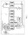
- FIG. 2 schematically represents the construction machine 1 according to the invention with the electric generator 10.
- the generator 10 is connected to electric power lines 10a to powerful consumers, for example, the heater 8a of the screed 8.
- the heater 8a is for heating an asphalt mix.
- the electrical power consumption of the heater 8a is mainly on the width of the screed 8 and optional, additionally connected consumers.
- the generator 10 has a control device 10b and a monitoring device 10c.
- the construction machine 1 further has a hydraulic system 11, which performs various hydraulic functions for the construction machine 1, for example, the adjustment of actuators.
- the at least two different circuits comprehensive hydraulic system 11 has a common for both circuits oil tank 12, which serves as a memory for hydraulic fluid.
- the hydraulic fluid in this example is a hydraulic oil because it has good lubricating properties and viscosity.
- the hydraulic oil is conveyed from the oil tank 12 by two pumps 13a, 13b connected to the oil tank 12, one of which is provided for each of the two different circuits of the hydraulic system 11.
- the hydraulic pumps 13a, 13b generate a continuous volume flow and have a design suitable for this task.
- the drive of the pumps 13a, 13b takes place in each case directly by the auxiliary drive 9. That is to say that the pumps 13a, 13b can permanently convey hydraulic oil from the oil tank 12 during operation of the internal combustion engine 7 and thus generate a largely constant pressure in the hydraulic system 11.
- the hydraulic system 11 further has two flow control valves 17a, 17b, which regulate the oil flow constant to a definable value between 4 and 10 liters per minute, but preferably about 8 liters per minute.
- the hydraulic system 11 performs various hydraulic functions for the construction machine 1.
- the hydraulic system 11 comprises hydraulic working components 18a to 18i connected thereto, e.g. Adjusting cylinder for the screed 8 or the chassis.
- Each working component 18a to 18i in each case comprises an electrically actuable valve 19a to 19i.
- the working components 18a to 18g are arranged in the circuit of the line system 16a and the working components 18h, 18i in the circuit of the line system 16b.
- the working components 18a to 18g require a constant volume flow, for which reason the two flow control valves 17a, 17b are arranged in the line system 16a between the pump 13a and the working components 18a to 18g.
- the working components 18h, 18i do not require a constant volume flow, so that between the pump 13b and the working components 18h, 18i no flow control valve is necessary.
- a return line 21 with a filter 22 connects the returns of the pipe systems 16 a, 16 b with the oil tank 12.
- the generator 10 has a helical pipe system 23, which is cast in a housing 24 of the generator 10, preferably in the form of a double jacket.
- the pipeline system 23 is connected to a hydraulic connection 25 to the flow of the hydraulic line 16 a of the hydraulic system 11.
- a further hydraulic port 26 is provided, which is connected to the return of the hydraulic line 16a. This is connected as a return to the oil tank 12, so that the hydraulic oil flows back into the oil tank 12.
- a pressure limiter 27 is provided.
- the pressure limiter 27 is a pressure relief valve, comprising a bypass with a check valve.
- the cooling of the electric generator 10 within the construction machine 1 can proceed as described below.
- the hydraulic system 11 In the construction machine 1, it may be necessary at the beginning of a labor input that the hydraulic system 11 is rapidly brought to an operating temperature. For example, the hydraulic oil only reaches an ideal viscosity for most components of the hydraulic system 11 at about 70 ° C.
- the cast in the housing 24 of the generator 10, helical pipe system 23 acts in this operating state of the construction machine 1 supportive to the hydraulic system 11, since it additionally heats the hydraulic oil with the heat generated by the generator 10.
- the hydraulic oil is delivered by the pump 13a both by the hydraulic system 11 and by the helical pipeline system 23 of the generator 10 in a substantially constant amount.
- the cooler 20 arranged in the return line of the piping system 16b allows heat to be released from the hydraulic oil to the environment, so that the temperature of the hydraulic oil in the piping system 16b is lowered.
- the controller 10b may limit the power consumption of the generator 10, whereby the generator 10 generates less self-heat.
- a not belonging to the invention construction machine 1 with electric generator 10 can be modified in many ways.
- the pumps 13a, 13b could be driven by an electric motor arranged separately in the construction machine 1.
- the oil pumps 13a, 13b would be driven as needed, and not permanently promote oil through the hydraulic system 11 and the piping system 23 of the generator 10. This would allow a particularly advantageous combination with an engine start-stop system.
- the helical pipeline system 23 of the generator 10 is connected to a further preheating circuit (not shown) in order to heat the generator 10 more quickly to a suitable operating temperature in cold outside temperatures.
Landscapes
- Engineering & Computer Science (AREA)
- Civil Engineering (AREA)
- Structural Engineering (AREA)
- Mining & Mineral Resources (AREA)
- General Engineering & Computer Science (AREA)
- Architecture (AREA)
- Power Engineering (AREA)
- Road Paving Machines (AREA)
- Fluid-Pressure Circuits (AREA)
- Component Parts Of Construction Machinery (AREA)
- Connection Of Motors, Electrical Generators, Mechanical Devices, And The Like (AREA)
Description
Die vorliegende Erfindung bezieht sich auf eine Baumaschine mit einem elektrischen Generator gemäß dem Oberbegriff des Anspruchs 1. Bei der Baumaschine kann es sich beispielsweise um einen Straßenfertiger oder Beschicker handeln.The present invention relates to a construction machine with an electric generator according to the preamble of
Aus der
Es ist weiter bekannt, dass in Kraft- und Nutzfahrzeugen eine andere Art elektrischer Generatoren, sogenannte Lichtmaschinen, zur Erzeugung der Bordnetzspannung eingesetzt werden. Weiter ist bekannt, dass auch diese elektrischen Generatoren während des Betriebs verschiedenen Wärmequellen ausgesetzt sind oder selbst Wärme erzeugen, weshalb sie zeitweise oder kontinuierlich gekühlt werden müssen. Einerseits befindet sich der Generator meist in der Nähe eines Verbrennungsmotors, andererseits erzeugt er während des Betriebs eine gewisse Eigenwärme. In Kraftfahrzeugen kann eine Luftkühlung des Generators ausreichend sein, in Fahrzeugen mit höherer Bordnetzspannung ist eine Flüssigkeitskühlung empfehlenswert. Ein flüssigkeitsgekühlter Generator ist beispielsweise aus der
Ein weiterer flüssigkeitsgekühlter Generator ist in der
Nachteilig am zitierten Stand der Technik ist, dass meist elektrisch leitfähiges Wasser in der Nähe elektrischer Bauteile eingesetzt wird.A disadvantage of the cited prior art is that usually electrically conductive water is used in the vicinity of electrical components.
Aus der
Die
Die
Die
Die
Die
Der Erfindung liegt die Aufgabe zugrunde, eine Baumaschine mit einem wirksam gekühlten Generator zur Verfügung zu stellen, wobei Mittel zur Kühlung des Generators an bereits in der Baumaschine vorliegende Systemkomponenten koppelbar sind, sodass die gesamte Anzahl an Betriebskomponenten der Baumaschine sowie deren Gesamtgewicht reduziert werden kann.The invention has for its object to provide a construction machine with an effectively cooled generator available, wherein means for cooling the generator can be coupled to existing in the construction machine system components, so that the total number of operating components of the construction machine and the total weight can be reduced.
Diese Aufgabe wird erfindungsgemäß gelöst durch eine Baumaschine mit einem elektrischen Generator mit den Merkmalen des Anspruchs 1. Vorteilhafte Weiterbildungen der Erfindung sind in den Unteransprüchen angegeben.This object is achieved by a construction machine with an electric generator having the features of
Erfindungsgemäß umfasst eine Baumaschine mit einem elektrischen Generator ein Hydraulikölsystem für Hydraulikfunktionen, wobei das Hydraulikölsystem zur Kühlung des Generators vorgesehen ist. Das Hydrauliköl hat zwar eine geringere Wärmekapazität als beispielsweise Wasser, wodurch das Öl im Vergleich zum Wasser weniger Wärme speichert. Vorteilhaft an der Verwendung von Hydrauliköl ist jedoch dessen hoher Siedepunkt im Vergleich zum Wasser, wodurch keine Additive beigemischt werden müssen. Ein weiterer Vorteil des Öls ist dessen gute elektrische Isoliereigenschaft, wodurch sich eine Leckage nicht negativ auf den elektrischen Generator auswirkt. Da das Hydraulikölsystem unabhängig vom elektrischen Generator in der Baumaschine vorgesehen ist und weitere Funktionen innerhalb der Baumaschine erfüllt, ist kein separates Kühlsystem für den elektrischen Generator notwendig. Des Weiteren ist der Wärmeeintrag in das Hydrauliksystem und damit dessen Temperatur meist niedriger als in einem Kühlsystem für einen Verbrennungsmotor.According to the invention, a construction machine with an electric generator comprises a hydraulic oil system for hydraulic functions, wherein the hydraulic oil system is provided for cooling the generator. Although the hydraulic oil has a lower heat capacity than, for example, water, the oil stores less heat compared to water. The advantage of using hydraulic oil, however, is its high boiling point compared to water, whereby no additives must be added. Another advantage of the oil is its good electrical insulating property, whereby a leakage does not adversely affect the electric generator. Since the hydraulic oil system is provided independently of the electric generator in the construction machine and fulfills other functions within the construction machine, no separate cooling system for the electric generator is necessary. Furthermore, the heat input into the hydraulic system and thus its temperature is usually lower than in a cooling system for an internal combustion engine.
Vorzugsweise weist der Generator für die Kühlung ein Rohrleitungssystem an seiner Außenoberfläche auf, wobei das Rohrleitungssystem an das Hydraulikölsystem angeschlossen ist. Je weitläufiger das Rohrleitungssystem ist, desto größer ist die wärmeleitende Oberfläche des Rohrleitungssystems und damit die Kühlleistung für den Generator.Preferably, the cooling generator comprises a piping system on its outer surface, the piping system being connected to the hydraulic oil system. The more extensive the piping system, the greater the heat-conducting surface of the piping system and thus the cooling capacity for the generator.
Für eine größtmögliche Kühlleistung des Systems ist das Rohrleitungssystem aus einem gut wärmeleitfähigen Material, vorzugsweise Stahl, Edelstahl, Aluminium oder Kupfer gefertigt.For the greatest possible cooling capacity of the system, the piping system is made of a good thermal conductivity material, preferably steel, stainless steel, aluminum or copper.
Um eine möglichst große Oberfläche des für die Kühlung vorgesehenen Rohrleitungssystems zu erreichen, hat das Rohrleitungssystem erfindungsgemäß eine Wendelform. Als besonders vorteilhaft hat sich ein Doppelmantel erwiesen, beispielsweise eine Halbrohrschlange. Um zu vermeiden, dass bei einem Kaltstart, bei dem das Öl eine hohe Viskosität aufweist, das gesamte Öl unter hohem Druck durch das Rohrleitungssystem des Generators gefördert wird, ist bei der Erfindung ein Druckbegrenzer im Rohrleitungssystem des Generators vorgesehen.In order to achieve the largest possible surface area of the pipe system provided for the cooling, the pipe system according to the invention has a helical shape. Particularly advantageous is a double jacket has been found, for example, a half-pipe coil. In order to avoid that during a cold start, in which the oil has a high viscosity, the entire oil is conveyed under high pressure through the piping system of the generator, a pressure limiter is provided in the piping system of the generator in the invention.
Eine besonders vorteilhafte Variante der Erfindung sieht eine Regeleinrichtung für den Generator vor, die unter anderem dazu konfiguriert ist, die Leistung des Generators zu regeln. So kann beispielsweise die Leistungsaufnahme des Generators bei hohen Temperaturen im oder um den Generator herum entsprechend reduziert werden.A particularly advantageous variant of the invention provides a control device for the generator, which is configured inter alia to regulate the power of the generator. For example, the power consumption of the generator at high temperatures in or around the generator can be reduced accordingly.
Eine weitere vorteilhafte Variante der Erfindung sieht einen Öltank vor, der das Hydrauliköl aus dem Rohrleitungssystem des Generators aufnimmt, wobei der Öltank weiter dazu eingerichtet ist, das Hydrauliköl aus dem Hydrauliksystem aufzunehmen. Die Nutzung eines gemeinsamen Öltanks spart Bauraum ein, so dass die Baumaschine insgesamt kompakter konstruiert werden kann.A further advantageous variant of the invention provides an oil tank, which receives the hydraulic oil from the piping system of the generator, wherein the oil tank is further adapted to receive the hydraulic oil from the hydraulic system. The use of a common oil tank saves space, so that the construction machine can be constructed more compact overall.
Besonders vorteilhaft ist es, wenn für die Kühlung des Hydrauliköls des Rohrleitungssystems und/oder des Hydrauliköls des Hydrauliksystems ein Wärmetauscher vorgesehen ist. Der Wärmetauscher kann dabei als reiner Kühler eingesetzt werden und die Wärme des Hydrauliköls an die Umgebung abgeben. Weiter wäre es denkbar, dass der Wärmetauscher an ein Heizungssystem der Baumaschine angeschlossen ist und die Wärme des Hydrauliksystems zum Heizen anderer Komponenten der Baumaschine verwendet wird.It is particularly advantageous if a heat exchanger is provided for the cooling of the hydraulic oil of the pipeline system and / or of the hydraulic oil of the hydraulic system. The heat exchanger can be used as a pure cooler and deliver the heat of the hydraulic oil to the environment. Further, it would be conceivable that the heat exchanger is connected to a heating system of the construction machine and the heat of the hydraulic system is used for heating other components of the construction machine.
Für einen effektiven und sicheren Betrieb des Generators kann es zweckmäßig sein, wenn eine Einrichtung für die Überwachung des Generators vorgesehen ist, wobei die Einrichtung idealerweise für das Zusammenwirken mit der Regeleinrichtung des Generators ausgebildet ist. So können unsichere und ineffiziente Betriebszustände des Generators diagnostiziert und darauf mit Ersatzmaßnahmen reagiert werden. Beispielsweise könnte die Leistungsaufnahme des Generators reduziert werden.For an effective and safe operation of the generator, it may be expedient if a device for monitoring the generator is provided, wherein the device is ideally designed for interaction with the control device of the generator. Thus, insecure and inefficient operating conditions of the generator can be diagnosed and reacted to with replacement measures. For example, the power consumption of the generator could be reduced.
Es hat sich als besonders effektiv herausgestellt, wenn das Rohrleitungssystem in ein Gehäuse des Generators integriert ist, da Luftspalte zwischen dem Rohrleitungssystem und dem Generator vermieden werden. Dies kann beispielsweise durch ein Eingießen des Rohrleitungssystems in das Gehäuse des Generators realisiert werden.It has been found to be particularly effective when the piping system is integrated into a housing of the generator, as air gaps between the piping system and the generator are avoided. This can be realized, for example, by pouring the pipeline system into the housing of the generator.
Die Erfindung sieht vor, dass der Generator für den Antrieb durch einen Verbrennungsmotor angetriebenen Nebenantrieb eingerichtet ist. Da der Verbrennungsmotor meist den Primärantrieb einer Baumaschine darstellt, kann der Generator so während des gesamten Betriebs der Baumaschine Elektrizität erzeugen. Darüber hinaus vermeidet der Antrieb des Generators mit einem zwischen dem Verbrennungsmotor und dem Generator angeordneten Nebenantrieb Drehmomentspitzen an der Generatoreingangswelle und erlaubt das Festlegen einer geeigneten Betriebsdrehzahl für den Generator.The invention provides that the generator is set up for driving by a combustion engine driven auxiliary drive. Since the internal combustion engine usually represents the primary drive of a construction machine, the generator can thus generate electricity during the entire operation of the construction machine. In addition, the drive of the generator with a PTO disposed between the engine and the generator avoids torque peaks on the generator input shaft and allows the setting of a suitable operating speed for the generator.
Um einen konstanten Druck im Hydrauliksystem und dem Rohrleitungssystem des Generators zu erzeugen, ist bei der Erfindung eine in dem Rohrleitungssystem druckerzeugende Ölpumpe vorgesehen, wobei die Ölpumpe weiter dazu eingerichtet ist, mit dem Hydrauliksystem zusammenzuwirken. So kann für das Hydrauliksystem und das Rohrleitungssystem des Generators eine gemeinsame Ölpumpe verwendet werden, wodurch eine zusätzliche Komponente und damit Bauraum eingespart werden kann.In order to produce a constant pressure in the hydraulic system and the piping system of the generator, the invention provides a pressure generating oil pump in the piping system, the oil pump being further adapted to cooperate with the hydraulic system. Thus, a common oil pump can be used for the hydraulic system and the piping system of the generator, whereby an additional component and thus space can be saved.
Erfindungsgemäß ist der mit dem Verbrennungsmotor verbundene Nebenantrieb für den Antrieb der Ölpumpe vorgesehen. So erzeugt die Ölpumpe während des gesamten Betriebs der Baumaschine den Öldruck für das Hydrauliksystem der Baumaschine und das Rohrleitungssystem des Generators.According to the invention associated with the engine PTO is provided for driving the oil pump. Thus, during the entire operation of the construction machine, the oil pump generates the oil pressure for the hydraulic system of the construction machine and the piping system of the generator.
Bei der Erfindung wird die Ölpumpe vom Nebenantrieb direkt betrieben, wobei optional zwischen dem Nebenantrieb und der Ölpumpe eine schaltbare Kupplung vorgesehen sein kann. So kann der Antrieb der Ölpumpe vom Verbrennungsmotor entkoppelt werden, was die Schleppverluste am Verbrennungsmotor reduziert. Damit kann ein permanenter Betrieb der Ölpumpe vermieden werden und vielmehr ein situatives Aufbauen des Öldrucks sowohl im Hydrauliksystem, als auch im Rohrleitungssystem des Generators erreicht werden.In the invention, the oil pump is operated directly by the auxiliary drive, wherein optionally a switchable coupling can be provided between the auxiliary drive and the oil pump. Thus, the drive of the oil pump can be decoupled from the internal combustion engine, which reduces the drag losses on the internal combustion engine. Thus, a permanent operation of the oil pump can be avoided and rather a situational building up of the oil pressure can be achieved both in the hydraulic system, as well as in the piping system of the generator.
Im Folgenden werden vorteilhafte Ausführungsbeispiele der Erfindung anhand einer Zeichnung näher erläutert. Im Einzelnen zeigen:
Figur 1- eine erfindungsgemäße Baumaschine in der Seitenansicht,
Figur 2- eine schematische Darstellung einer erfindungsgemäßen Baumaschine mit einem elektrischen Generator.
- FIG. 1
- a construction machine according to the invention in side view,
- FIG. 2
- a schematic representation of a construction machine according to the invention with an electric generator.
Gleiche Komponenten sind in den Figuren durchgängig mit gleichen Bezugszeichen versehen.The same components are provided throughout the figures with the same reference numerals.
Die Baumaschine 1 verfügt über einen Aufbau 2, der einen Bedienstand 3 aufnimmt. Der Aufbau 2 wird von einem Fahrgestell 4 getragen. Das Fahrgestell 4 überträgt Antriebskräfte mittels Rädern 5 oder Raupen (nicht dargestellt) auf die Fahrbahn 6. Für die Erzeugung der Antriebskräfte verfügt der Aufbau 2 über einen Verbrennungsmotor 7 als Primärantriebsquelle, der in diesem Beispiel ein Dieselmotor ist. Am hinteren Bereich des Aufbaus 2 ist eine Einbaubohle 8 mit einer Heizeinrichtung 8a montiert.The
Mit der Kurbelwelle des Verbrennungsmotors 7 ist ein Nebenantrieb 9, in diesem Ausführungsbeispiel ein Pumpenverteilergetriebe, verbunden. Mit einem Ausgang des Nebenantriebs 9 ist die Antriebswelle eines elektrischen Generators 10 über einen Riemenantrieb 11, einer Gelenkwelle oder auch direkt mit dem Nebenantrieb verbunden, um eine Spannung für leistungsstarke Verbraucher der Baumaschine 1, beispielsweise die Heizeinrichtung 8a der Einbaubohle 8, zu erzeugen. Die vom Generator 10 erzeugte Betriebsspannung beträgt etwa 400 V. Die Funktion des Generators 10 innerhalb der Baumaschine 1 wird nachfolgend unter Bezug auf die
Die Baumaschine 1 verfügt weiter über ein Hydrauliksystem 11, das verschiedene Hydraulikfunktionen für die Baumaschine 1 ausführt, beispielsweise das Verstellen von Aktuatoren. Das wenigstens zwei unterschiedliche Kreisläufe umfassende Hydrauliksystem 11 weist einen für beide Kreisläufe gemeinsamen Öltank 12 auf, der als Speicher für Hydraulikflüssigkeit dient. Die Hydraulikflüssigkeit ist in diesem Beispiel ein Hydrauliköl, da dieses gute Schmiereigenschaften und eine geeignete Viskosität besitzt.The
Das Hydrauliköl wird von zwei an den Öltank 12 angeschlossenen Pumpen 13a, 13b aus dem Öltank 12 gefördert, von denen jeweils eine für die zwei unterschiedlichen Kreisläufe des Hydrauliksystems 11 vorgesehen ist. Die Hydraulikpumpen 13a, 13b erzeugen dabei einen kontinuierlichen Volumenstrom und weisen eine für diese Aufgabe geeignete Bauform auf. Der Antrieb der Pumpen 13a, 13b erfolgt jeweils direkt durch den Nebenantrieb 9. Das heißt, dass die Pumpen 13a, 13b während des Betriebs des Verbrennungsmotors 7 permanent Hydrauliköl aus dem Öltank 12 fördern können und so einen weitgehend konstanten Druck im Hydrauliksystem 11 erzeugen.The hydraulic oil is conveyed from the
Das Hydrauliksystem 11 verfügt weiter über zwei Stromregelventile 17a, 17b, die den Ölfluss konstant auf einen festlegbaren Wert zwischen 4 und 10 Litern pro Minute, vorzugsweise jedoch etwa 8 Liter pro Minute, regeln.The
Das Hydrauliksystem 11 erfüllt verschiedene Hydraulikfunktionen für die Baumaschine 1. Dafür umfasst das Hydrauliksystem 11 über daran angeschlossene hydraulische Arbeitskomponenten 18a bis 18i, z.B. Verstellzylinder für die Einbaubohle 8 oder das Fahrwerk. Jede Arbeitskomponente 18a bis 18i umfasst dabei jeweils ein elektrisch betätigbares Ventil 19a bis 19i. In diesem Ausführungsbeispiel sind die Arbeitskomponenten 18a bis 18g im Kreislauf des Leitungssystems 16a und die Arbeitskomponenten 18h, 18i im Kreislauf des Leitungssystems 16b angeordnet.The
Die Arbeitskomponenten 18a bis 18g benötigen einen konstanten Volumenstrom, weshalb zwischen der Pumpe 13a und den Arbeitskomponenten 18a bis 18g die beiden Stromregelventile 17a, 17b im Leitungssystem 16a angeordnet sind. Die Arbeitskomponenten 18h, 18i benötigen keinen konstanten Volumenstrom, so dass zwischen der Pumpe 13b und den Arbeitskomponenten 18h, 18i kein Strömungsregelungsventil notwendig ist. Zwischen den hydraulischen Arbeitskomponenten 18h, 18i und dem Öltank 12 befindet sich im Rücklauf des Leitungssystems 16b ein Wärmetauscher 20, in diesem Beispiel ein Kühler, um die Temperatur des durch die hydraulischen Arbeitskomponenten 18h, 18i erwärmten Hydrauliköls zu beeinflussen. Eine Rücklaufleitung 21 mit einem Filter 22 verbindet die Rückläufe der Leitungssysteme 16a, 16b mit dem Öltank 12.The working
Der Generator 10 verfügt über ein wendelförmiges Rohrleitungssystem 23, das in ein Gehäuse 24 des Generators 10, vorzugsweise in Form eines Doppelmantels, eingegossen ist. Das Rohrleitungssystem 23 ist mit einem Hydraulikanschluss 25 an den Vorlauf der Hydraulikleitung 16a des Hydrauliksystems 11 angeschlossen. Durch die Regelung des Strömungsregelungsventils 17a herrscht ein konstanter Öldurchfluss im Rohrleitungssystem 23 des Generators 10. An einem Ende des Rohrleitungssystems 23 ist ein weiterer Hydraulikanschluss 26 vorgesehen, der mit dem Rücklauf der Hydraulikleitung 16a verbunden ist. Dieser ist als Rücklauf mit dem Öltank 12 verbunden, so dass das Hydrauliköl in den Öltank 12 zurückfließt.The
Zur Begrenzung des Systemdrucks im Rohrleitungssystem 23 ist ein Druckbegrenzer 27 vorgesehen. In diesem Ausführungsbeispiel ist der Druckbegrenzer 27 ein Druckbegrenzungsventil, umfassend einen Bypass mit Rückschlagventil.To limit the system pressure in the
Die Kühlung des elektrischen Generators 10 innerhalb der Baumaschine 1 kann wie nachfolgend beschrieben ablaufen.The cooling of the
In der Baumaschine 1 kann es zu Beginn eines Arbeitseinsatzes notwendig sein, dass das Hydrauliksystem 11 zügig auf eine Betriebstemperatur gebracht wird. Beispielsweise erreicht das Hydrauliköl erst bei etwa 70 °C eine für die meisten Komponenten des Hydrauliksystems 11 ideale Viskosität. Das in das Gehäuse 24 des Generators 10 eingegossene, wendelförmige Rohrleitungssystem 23 wirkt in diesem Betriebszustand der Baumaschine 1 unterstützend auf das Hydrauliksystem 11, da es mit der vom Generator 10 erzeugten Wärme das Hydrauliköl zusätzlich aufheizt.In the
Das Hydrauliköl wird während des Betriebs des Verbrennungsmotors 7 bzw. des Nebenantriebs 9 von der Pumpe 13a sowohl durch das Hydrauliksystem 11, als auch durch das wendelförmige Rohrleitungssystem 23 des Generators 10 in einer weitgehend konstanten Menge gefördert.During the operation of the internal combustion engine 7 or the
Durch den Energieeintrag der Arbeitskomponenten 18a bis 18i und die erzeugte, an das Hydrauliköl abgegebene, Eigenwärme des Generators 10 wird das Hydrauliköl während des weiteren Betriebs der Baumaschine 1 stark erwärmt. Der im Rücklauf des Leitungssystems 16b angeordnete Kühler 20 ermöglicht eine Wärmeabgabe vom Hydrauliköl an die Umgebung, so dass die Temperatur des Hydrauliköls im Leitungssystem 16b gesenkt wird.Due to the energy input of the working
Da das so gekühlte Hydrauliköl aus dem Kreislauf mit dem Leitungssystem 16b des Hydrauliksystems 11 in den gemeinsamen Öltank 12 fließt und sich darin mit dem ungekühlten Hydrauliköl aus dem Kreislauf des Rohrleitungssystems 16a des Generators 10 bzw. der Arbeitskomponenten 18a bis 18g im Öltank 12 vermischt, wird das Hydrauliköl vom Generator 10 gekühlt, bevor es von der Pumpe 13a erneut gefördert und dem Rohrleitungssystem 23 zugeführt wird. Ist die Kühlung des Generators 10 durch das Hydrauliköl nicht ausreichend und wird dies von der Überwachungseinrichtung 10c detektiert, kann die Regeleinrichtung 10b die Leistungsaufnahme des Generators 10 begrenzen, wodurch der Generator 10 weniger Eigenwärme erzeugt.Since the thus cooled hydraulic oil from the circuit flows with the piping 16 b of the
Ausgehend von dem dargestellten Ausführungsbeispiel kann eine nicht zur Erfindung gehörende Baumaschine 1 mit elektrischem Generator 10 auf vielfache Weise abgewandelt werden. Beispielsweise könnten die Pumpen 13a, 13b anstatt vom Verbrennungsmotor 7 bzw. des Nebenantriebs 9 von einem separat in der Baumaschine 1 angeordneten Elektromotor angetrieben werden. Somit würden die Ölpumpen 13a, 13b bedarfsgerecht angesteuert werden, und nicht permanent Öl durch das Hydrauliksystem 11 und das Rohrleitungssystem 23 des Generators 10 fördern. Dies würde eine besonders vorteilhafte Kombination mit einem Motor-Start-Stopp-System ermöglichen.Starting from the illustrated embodiment, a not belonging to the
Erfindungsgemäß ist das wendelförmige Rohrleitungssystem 23 des Generators 10 an einen weiteren Vorwärmkreislauf (nicht gezeigt) angeschlossen, um den Generator 10 bei kalten Außentemperaturen zügiger auf eine geeignete Betriebstemperatur zu erwärmen.According to the invention, the
Claims (8)
- Construction machine (1) with an electric generator (10), wherein the construction machine (1) further comprises a hydraulic oil system (11) for hydraulic functions, wherein the hydraulic oil system (11) is provided for cooling the generator (10), wherein for cooling, the generator (10) has on its outer surface a pipe system (23), wherein the pipe system (23) is connected to the hydraulic oil system (11), wherein a pressure-generating oil pump (13a) is provided in the hydraulic oil system (11), wherein the oil pump (13a) is set up to interact with the hydraulic oil system (11), wherein for cooling the generator (10) the oil pump (13a) is configured to convey hydraulic oil via the hydraulic oil system (11) through the pipe system (23), which is connected thereto, of the generator (10), wherein the generator (10) is set up to be driven by a combustion engine (7), wherein at least one pressure limiter (27) is provided in the pipe system (23), and wherein the pipe system (23) has a coil shape,
characterized in that
the combustion engine (7) is functionally connected to an auxiliary drive (9) which is provided for the drive of the generator (10) and also for the drive of the oil pump (13a), and
the coil-shaped pipe system (23) of the generator (10) is connected to a pre-heating circuit in order to heat the generator (10) more speedily to a suitable operating temperature in the event of cold external temperatures. - Construction machine according to claim 1, characterized in that the pipe system (23) is manufactured from a heat-conducting material, preferably steel, stainless steel, aluminum or copper.
- Construction machine according to one of the preceding claims, characterized in that the pipe system (23) is a double casing on the outer surface of the generator (10).
- Construction machine according to one of the preceding claims, characterized in that an oil tank (12) is provided that holds the hydraulic oil, wherein the oil tank (12) is additionally set up to hold the hydraulic oil from the hydraulic oil system (11).
- Construction machine according to one of the preceding claims, characterized in in that a heat exchanger (20) is provided for the cooling of the hydraulic oil of the pipe system (23) and/or of the hydraulic oil of the hydraulic oil system (11).
- Construction machine according to one of the preceding claims, characterized in that a regulating device (10b) is provided for the generator (10), wherein this regulating device (10b) is configured to regulate the output of the generator (10).
- Construction machine according to claim 6, characterized in that a device (10c) is provided for monitoring the generator (10), wherein the device (10c) is formed to interact with the regulating device (10b).
- Construction machine according to one of the preceding claims, characterized in that the pipe system (23) is integrated into a housing (24) of the generator (10).
Priority Applications (5)
| Application Number | Priority Date | Filing Date | Title |
|---|---|---|---|
| EP11007087.7A EP2565334B1 (en) | 2011-08-31 | 2011-08-31 | Construction machine with oil-cooled generator |
| PL11007087T PL2565334T3 (en) | 2011-08-31 | 2011-08-31 | Construction machine with oil-cooled generator |
| US13/597,796 US9722473B2 (en) | 2011-08-31 | 2012-08-29 | Construction machine with oil-cooled generator |
| JP2012188558A JP6222538B2 (en) | 2011-08-31 | 2012-08-29 | Construction machinery with oil-cooled generator |
| CN201210320549.XA CN102966024B (en) | 2011-08-31 | 2012-08-31 | There is the building machinery of oil-cooled generator |
Applications Claiming Priority (1)
| Application Number | Priority Date | Filing Date | Title |
|---|---|---|---|
| EP11007087.7A EP2565334B1 (en) | 2011-08-31 | 2011-08-31 | Construction machine with oil-cooled generator |
Publications (2)
| Publication Number | Publication Date |
|---|---|
| EP2565334A1 EP2565334A1 (en) | 2013-03-06 |
| EP2565334B1 true EP2565334B1 (en) | 2016-10-05 |
Family
ID=44581991
Family Applications (1)
| Application Number | Title | Priority Date | Filing Date |
|---|---|---|---|
| EP11007087.7A Active EP2565334B1 (en) | 2011-08-31 | 2011-08-31 | Construction machine with oil-cooled generator |
Country Status (5)
| Country | Link |
|---|---|
| US (1) | US9722473B2 (en) |
| EP (1) | EP2565334B1 (en) |
| JP (1) | JP6222538B2 (en) |
| CN (1) | CN102966024B (en) |
| PL (1) | PL2565334T3 (en) |
Families Citing this family (5)
| Publication number | Priority date | Publication date | Assignee | Title |
|---|---|---|---|---|
| DE102013008032B4 (en) * | 2013-05-13 | 2023-12-21 | Dynapac Gmbh | Method and device for electrically heating a paver screed |
| US9711473B1 (en) * | 2016-02-26 | 2017-07-18 | Advanced Semiconductor Engineering, Inc. | Semiconductor die, semiconductor wafer and method for manufacturing the same |
| DE102016009086A1 (en) * | 2016-07-26 | 2018-02-01 | Bomag Gmbh | Hand-guided soil compaction machine, in particular vibration rammer or vibrating plate |
| US20220259825A1 (en) * | 2021-02-18 | 2022-08-18 | Deere & Company | Preheating intelligence for electric-hydraulic work vehicles |
| CN114351540B (en) * | 2022-01-19 | 2023-06-30 | 南京欣三人行网络科技有限公司 | Asphalt paver capable of converting heat energy into electric energy |
Citations (1)
| Publication number | Priority date | Publication date | Assignee | Title |
|---|---|---|---|---|
| EP2256247A1 (en) * | 2009-05-25 | 2010-12-01 | Joseph Vögele AG | Road finisher |
Family Cites Families (18)
| Publication number | Priority date | Publication date | Assignee | Title |
|---|---|---|---|---|
| JPS5556467U (en) * | 1978-10-09 | 1980-04-16 | ||
| DE3028177C2 (en) | 1980-07-25 | 1986-08-14 | Brown, Boveri & Cie Ag, 6800 Mannheim | Liquid-cooled generator |
| US4516044A (en) * | 1984-05-31 | 1985-05-07 | Cincinnati Milacron Inc. | Heat exchange apparatus for electric motor and electric motor equipped therewith |
| DE19750379B4 (en) | 1997-07-30 | 2007-12-13 | Linde Material Handling Gmbh | Assembly with an electric generator and a pump unit |
| DE19854464C2 (en) | 1998-06-20 | 2000-05-18 | Daimler Chrysler Ag | Liquid cooled generator |
| JP2001016827A (en) | 1999-06-30 | 2001-01-19 | Kobelco Contstruction Machinery Ltd | Construction machine |
| DE20001039U1 (en) | 2000-01-21 | 2000-03-30 | Voegele Ag J | Paver |
| CN2433295Y (en) * | 2000-07-11 | 2001-06-06 | 三一重工股份有限公司 | Circulation lubricating cooling structure of vibration roller |
| JP4179465B2 (en) | 2002-07-31 | 2008-11-12 | 株式会社小松製作所 | Construction machinery |
| DE102007012702A1 (en) * | 2007-01-29 | 2008-07-31 | Robert Bosch Gmbh | Generator controlling method for use in motor vehicle, involves presetting target output voltage of generator, and comparing measured actual temperature with preset temperature threshold |
| US20090102298A1 (en) * | 2007-10-19 | 2009-04-23 | Caterpillar Inc. | Cooling housing for an electric device |
| JP4883058B2 (en) * | 2008-08-28 | 2012-02-22 | ダイキン工業株式会社 | Construction machinery |
| JP5421074B2 (en) * | 2008-11-10 | 2014-02-19 | 住友重機械工業株式会社 | Hybrid construction machine |
| JP5674086B2 (en) * | 2008-11-10 | 2015-02-25 | 住友重機械工業株式会社 | Hybrid construction machine |
| JP5396882B2 (en) * | 2009-01-23 | 2014-01-22 | コベルコ建機株式会社 | Electric motor cooling device for hybrid work machine |
| EP2429871B1 (en) * | 2009-05-12 | 2013-02-20 | El-Forest AB | Energy system for a hybrid vehicle |
| WO2010147121A1 (en) * | 2009-06-19 | 2010-12-23 | 住友重機械工業株式会社 | Hybrid construction machine and control method for hybrid construction machine |
| CN201581331U (en) * | 2009-11-27 | 2010-09-15 | 徐州凯莫尔重工科技有限公司 | Cooling system of spreading machine |
-
2011
- 2011-08-31 PL PL11007087T patent/PL2565334T3/en unknown
- 2011-08-31 EP EP11007087.7A patent/EP2565334B1/en active Active
-
2012
- 2012-08-29 JP JP2012188558A patent/JP6222538B2/en active Active
- 2012-08-29 US US13/597,796 patent/US9722473B2/en active Active
- 2012-08-31 CN CN201210320549.XA patent/CN102966024B/en active Active
Patent Citations (1)
| Publication number | Priority date | Publication date | Assignee | Title |
|---|---|---|---|---|
| EP2256247A1 (en) * | 2009-05-25 | 2010-12-01 | Joseph Vögele AG | Road finisher |
Also Published As
| Publication number | Publication date |
|---|---|
| US20130051912A1 (en) | 2013-02-28 |
| CN102966024A (en) | 2013-03-13 |
| JP2013053512A (en) | 2013-03-21 |
| JP6222538B2 (en) | 2017-11-01 |
| CN102966024B (en) | 2016-01-20 |
| EP2565334A1 (en) | 2013-03-06 |
| PL2565334T3 (en) | 2017-07-31 |
| US9722473B2 (en) | 2017-08-01 |
Similar Documents
| Publication | Publication Date | Title |
|---|---|---|
| EP2565334B1 (en) | Construction machine with oil-cooled generator | |
| EP2559879B1 (en) | Drive unit with two couple-able cooling circuits to preheat a combustion engine and method | |
| EP1108572B1 (en) | Heat exchange system for the heating of a vehicle with hybrid propulsion | |
| DE102013226804B4 (en) | Drive arrangement with integrated lubrication | |
| DE102011078088A1 (en) | cooling system | |
| DE10318744B4 (en) | cooling system | |
| DE102015007235A1 (en) | Work machine, in particular dump truck or truck | |
| DE102011115279A1 (en) | Drive arrangement for motor vehicle, has electric motor and transmission, where electric motor has cooling circuit with cooling medium and transmission has lubricating circuit with lubricating medium | |
| DE102012200391A1 (en) | Refrigerant circuit for e.g. diesel combustion engine of e.g. passenger car, has electrical coolant pump that conveys coolant directly to coolant return line through crankcase and/or cylinder head | |
| DE102009058575A1 (en) | Cooling circuit of an internal combustion engine and a working method for operating a cooling circuit | |
| EP2770170B1 (en) | Waste heat reuse system, in particular for a motor vehicle, with a feed pump | |
| EP3405660B1 (en) | Cooling system after engine shut-down, cylinder head, and method for operating a cooling system after engine shut-down | |
| EP0931209B1 (en) | Drive unit with a thermally regulated water pump | |
| EP2108813B1 (en) | Device for cooling or heating a combustion engine | |
| DE102013015207B4 (en) | Cooling system for a hybrid vehicle comprising at least one electric drive machine and at least one internal combustion engine and method for its regulation | |
| EP2647106A2 (en) | Liquid delivery device | |
| DE102009058131B4 (en) | contraption | |
| DE102012025436A1 (en) | Internal combustion engine | |
| DE102009000777A1 (en) | Gear box i.e. stepless gearbox, efficiency improving method for agricultural vehicle, involves interrupting feed stream to heat exchanger by valve when oil temperature reaches to preset temperature, and deactivating bridging of cooler | |
| EP1881586B1 (en) | Cooling system particularly for a vehicle | |
| DE102004018227A1 (en) | cooling system | |
| EP0664381B1 (en) | Internal combustion engine with cooling means circuit | |
| WO2010057719A1 (en) | Cooling system | |
| DE10211060B4 (en) | Method and device for controlling the coolant volume flow in an internal combustion engine | |
| DE102010036692A1 (en) | Drive arrangement for hydraulic auxiliary unit e.g. power steering apparatus in motor car, has branch line whose input is connected with output side of hydraulic pump which is guidance assistance pump of power steering apparatus |
Legal Events
| Date | Code | Title | Description |
|---|---|---|---|
| PUAI | Public reference made under article 153(3) epc to a published international application that has entered the european phase |
Free format text: ORIGINAL CODE: 0009012 |
|
| 17P | Request for examination filed |
Effective date: 20120727 |
|
| AK | Designated contracting states |
Kind code of ref document: A1 Designated state(s): AL AT BE BG CH CY CZ DE DK EE ES FI FR GB GR HR HU IE IS IT LI LT LU LV MC MK MT NL NO PL PT RO RS SE SI SK SM TR |
|
| AX | Request for extension of the european patent |
Extension state: BA ME |
|
| GRAP | Despatch of communication of intention to grant a patent |
Free format text: ORIGINAL CODE: EPIDOSNIGR1 |
|
| INTG | Intention to grant announced |
Effective date: 20160331 |
|
| GRAS | Grant fee paid |
Free format text: ORIGINAL CODE: EPIDOSNIGR3 |
|
| GRAA | (expected) grant |
Free format text: ORIGINAL CODE: 0009210 |
|
| AK | Designated contracting states |
Kind code of ref document: B1 Designated state(s): AL AT BE BG CH CY CZ DE DK EE ES FI FR GB GR HR HU IE IS IT LI LT LU LV MC MK MT NL NO PL PT RO RS SE SI SK SM TR |
|
| REG | Reference to a national code |
Ref country code: GB Ref legal event code: FG4D Free format text: NOT ENGLISH |
|
| REG | Reference to a national code |
Ref country code: CH Ref legal event code: EP |
|
| REG | Reference to a national code |
Ref country code: AT Ref legal event code: REF Ref document number: 834807 Country of ref document: AT Kind code of ref document: T Effective date: 20161015 |
|
| REG | Reference to a national code |
Ref country code: IE Ref legal event code: FG4D Free format text: LANGUAGE OF EP DOCUMENT: GERMAN |
|
| REG | Reference to a national code |
Ref country code: DE Ref legal event code: R096 Ref document number: 502011010816 Country of ref document: DE |
|
| REG | Reference to a national code |
Ref country code: NL Ref legal event code: MP Effective date: 20161005 |
|
| REG | Reference to a national code |
Ref country code: LT Ref legal event code: MG4D |
|
| PG25 | Lapsed in a contracting state [announced via postgrant information from national office to epo] |
Ref country code: LV Free format text: LAPSE BECAUSE OF FAILURE TO SUBMIT A TRANSLATION OF THE DESCRIPTION OR TO PAY THE FEE WITHIN THE PRESCRIBED TIME-LIMIT Effective date: 20161005 |
|
| PG25 | Lapsed in a contracting state [announced via postgrant information from national office to epo] |
Ref country code: GR Free format text: LAPSE BECAUSE OF FAILURE TO SUBMIT A TRANSLATION OF THE DESCRIPTION OR TO PAY THE FEE WITHIN THE PRESCRIBED TIME-LIMIT Effective date: 20170106 Ref country code: LT Free format text: LAPSE BECAUSE OF FAILURE TO SUBMIT A TRANSLATION OF THE DESCRIPTION OR TO PAY THE FEE WITHIN THE PRESCRIBED TIME-LIMIT Effective date: 20161005 Ref country code: NO Free format text: LAPSE BECAUSE OF FAILURE TO SUBMIT A TRANSLATION OF THE DESCRIPTION OR TO PAY THE FEE WITHIN THE PRESCRIBED TIME-LIMIT Effective date: 20170105 Ref country code: SE Free format text: LAPSE BECAUSE OF FAILURE TO SUBMIT A TRANSLATION OF THE DESCRIPTION OR TO PAY THE FEE WITHIN THE PRESCRIBED TIME-LIMIT Effective date: 20161005 |
|
| PG25 | Lapsed in a contracting state [announced via postgrant information from national office to epo] |
Ref country code: IS Free format text: LAPSE BECAUSE OF FAILURE TO SUBMIT A TRANSLATION OF THE DESCRIPTION OR TO PAY THE FEE WITHIN THE PRESCRIBED TIME-LIMIT Effective date: 20170205 Ref country code: ES Free format text: LAPSE BECAUSE OF FAILURE TO SUBMIT A TRANSLATION OF THE DESCRIPTION OR TO PAY THE FEE WITHIN THE PRESCRIBED TIME-LIMIT Effective date: 20161005 Ref country code: NL Free format text: LAPSE BECAUSE OF FAILURE TO SUBMIT A TRANSLATION OF THE DESCRIPTION OR TO PAY THE FEE WITHIN THE PRESCRIBED TIME-LIMIT Effective date: 20161005 Ref country code: FI Free format text: LAPSE BECAUSE OF FAILURE TO SUBMIT A TRANSLATION OF THE DESCRIPTION OR TO PAY THE FEE WITHIN THE PRESCRIBED TIME-LIMIT Effective date: 20161005 Ref country code: PT Free format text: LAPSE BECAUSE OF FAILURE TO SUBMIT A TRANSLATION OF THE DESCRIPTION OR TO PAY THE FEE WITHIN THE PRESCRIBED TIME-LIMIT Effective date: 20170206 Ref country code: RS Free format text: LAPSE BECAUSE OF FAILURE TO SUBMIT A TRANSLATION OF THE DESCRIPTION OR TO PAY THE FEE WITHIN THE PRESCRIBED TIME-LIMIT Effective date: 20161005 Ref country code: HR Free format text: LAPSE BECAUSE OF FAILURE TO SUBMIT A TRANSLATION OF THE DESCRIPTION OR TO PAY THE FEE WITHIN THE PRESCRIBED TIME-LIMIT Effective date: 20161005 |
|
| REG | Reference to a national code |
Ref country code: DE Ref legal event code: R097 Ref document number: 502011010816 Country of ref document: DE |
|
| PG25 | Lapsed in a contracting state [announced via postgrant information from national office to epo] |
Ref country code: CZ Free format text: LAPSE BECAUSE OF FAILURE TO SUBMIT A TRANSLATION OF THE DESCRIPTION OR TO PAY THE FEE WITHIN THE PRESCRIBED TIME-LIMIT Effective date: 20161005 Ref country code: EE Free format text: LAPSE BECAUSE OF FAILURE TO SUBMIT A TRANSLATION OF THE DESCRIPTION OR TO PAY THE FEE WITHIN THE PRESCRIBED TIME-LIMIT Effective date: 20161005 Ref country code: SK Free format text: LAPSE BECAUSE OF FAILURE TO SUBMIT A TRANSLATION OF THE DESCRIPTION OR TO PAY THE FEE WITHIN THE PRESCRIBED TIME-LIMIT Effective date: 20161005 Ref country code: DK Free format text: LAPSE BECAUSE OF FAILURE TO SUBMIT A TRANSLATION OF THE DESCRIPTION OR TO PAY THE FEE WITHIN THE PRESCRIBED TIME-LIMIT Effective date: 20161005 Ref country code: RO Free format text: LAPSE BECAUSE OF FAILURE TO SUBMIT A TRANSLATION OF THE DESCRIPTION OR TO PAY THE FEE WITHIN THE PRESCRIBED TIME-LIMIT Effective date: 20161005 |
|
| PLBE | No opposition filed within time limit |
Free format text: ORIGINAL CODE: 0009261 |
|
| STAA | Information on the status of an ep patent application or granted ep patent |
Free format text: STATUS: NO OPPOSITION FILED WITHIN TIME LIMIT |
|
| REG | Reference to a national code |
Ref country code: FR Ref legal event code: PLFP Year of fee payment: 7 |
|
| PG25 | Lapsed in a contracting state [announced via postgrant information from national office to epo] |
Ref country code: BG Free format text: LAPSE BECAUSE OF FAILURE TO SUBMIT A TRANSLATION OF THE DESCRIPTION OR TO PAY THE FEE WITHIN THE PRESCRIBED TIME-LIMIT Effective date: 20170105 Ref country code: SM Free format text: LAPSE BECAUSE OF FAILURE TO SUBMIT A TRANSLATION OF THE DESCRIPTION OR TO PAY THE FEE WITHIN THE PRESCRIBED TIME-LIMIT Effective date: 20161005 |
|
| 26N | No opposition filed |
Effective date: 20170706 |
|
| PG25 | Lapsed in a contracting state [announced via postgrant information from national office to epo] |
Ref country code: SI Free format text: LAPSE BECAUSE OF FAILURE TO SUBMIT A TRANSLATION OF THE DESCRIPTION OR TO PAY THE FEE WITHIN THE PRESCRIBED TIME-LIMIT Effective date: 20161005 |
|
| REG | Reference to a national code |
Ref country code: CH Ref legal event code: PL |
|
| PG25 | Lapsed in a contracting state [announced via postgrant information from national office to epo] |
Ref country code: MC Free format text: LAPSE BECAUSE OF FAILURE TO SUBMIT A TRANSLATION OF THE DESCRIPTION OR TO PAY THE FEE WITHIN THE PRESCRIBED TIME-LIMIT Effective date: 20161005 |
|
| PG25 | Lapsed in a contracting state [announced via postgrant information from national office to epo] |
Ref country code: LI Free format text: LAPSE BECAUSE OF NON-PAYMENT OF DUE FEES Effective date: 20170831 Ref country code: CH Free format text: LAPSE BECAUSE OF NON-PAYMENT OF DUE FEES Effective date: 20170831 |
|
| REG | Reference to a national code |
Ref country code: IE Ref legal event code: MM4A |
|
| REG | Reference to a national code |
Ref country code: BE Ref legal event code: MM Effective date: 20170831 |
|
| PG25 | Lapsed in a contracting state [announced via postgrant information from national office to epo] |
Ref country code: LU Free format text: LAPSE BECAUSE OF NON-PAYMENT OF DUE FEES Effective date: 20170831 |
|
| PG25 | Lapsed in a contracting state [announced via postgrant information from national office to epo] |
Ref country code: IE Free format text: LAPSE BECAUSE OF NON-PAYMENT OF DUE FEES Effective date: 20170831 |
|
| REG | Reference to a national code |
Ref country code: FR Ref legal event code: PLFP Year of fee payment: 8 |
|
| PG25 | Lapsed in a contracting state [announced via postgrant information from national office to epo] |
Ref country code: BE Free format text: LAPSE BECAUSE OF NON-PAYMENT OF DUE FEES Effective date: 20170831 |
|
| PG25 | Lapsed in a contracting state [announced via postgrant information from national office to epo] |
Ref country code: MT Free format text: LAPSE BECAUSE OF FAILURE TO SUBMIT A TRANSLATION OF THE DESCRIPTION OR TO PAY THE FEE WITHIN THE PRESCRIBED TIME-LIMIT Effective date: 20161005 |
|
| REG | Reference to a national code |
Ref country code: AT Ref legal event code: MM01 Ref document number: 834807 Country of ref document: AT Kind code of ref document: T Effective date: 20170831 |
|
| PG25 | Lapsed in a contracting state [announced via postgrant information from national office to epo] |
Ref country code: AT Free format text: LAPSE BECAUSE OF NON-PAYMENT OF DUE FEES Effective date: 20170831 |
|
| PG25 | Lapsed in a contracting state [announced via postgrant information from national office to epo] |
Ref country code: HU Free format text: LAPSE BECAUSE OF FAILURE TO SUBMIT A TRANSLATION OF THE DESCRIPTION OR TO PAY THE FEE WITHIN THE PRESCRIBED TIME-LIMIT; INVALID AB INITIO Effective date: 20110831 |
|
| PG25 | Lapsed in a contracting state [announced via postgrant information from national office to epo] |
Ref country code: CY Free format text: LAPSE BECAUSE OF NON-PAYMENT OF DUE FEES Effective date: 20161005 |
|
| PG25 | Lapsed in a contracting state [announced via postgrant information from national office to epo] |
Ref country code: MK Free format text: LAPSE BECAUSE OF FAILURE TO SUBMIT A TRANSLATION OF THE DESCRIPTION OR TO PAY THE FEE WITHIN THE PRESCRIBED TIME-LIMIT Effective date: 20161005 |
|
| PG25 | Lapsed in a contracting state [announced via postgrant information from national office to epo] |
Ref country code: TR Free format text: LAPSE BECAUSE OF FAILURE TO SUBMIT A TRANSLATION OF THE DESCRIPTION OR TO PAY THE FEE WITHIN THE PRESCRIBED TIME-LIMIT Effective date: 20161005 |
|
| PG25 | Lapsed in a contracting state [announced via postgrant information from national office to epo] |
Ref country code: AL Free format text: LAPSE BECAUSE OF FAILURE TO SUBMIT A TRANSLATION OF THE DESCRIPTION OR TO PAY THE FEE WITHIN THE PRESCRIBED TIME-LIMIT Effective date: 20161005 |
|
| P01 | Opt-out of the competence of the unified patent court (upc) registered |
Effective date: 20230524 |
|
| PGFP | Annual fee paid to national office [announced via postgrant information from national office to epo] |
Ref country code: IT Payment date: 20230829 Year of fee payment: 13 Ref country code: GB Payment date: 20230824 Year of fee payment: 13 |
|
| PGFP | Annual fee paid to national office [announced via postgrant information from national office to epo] |
Ref country code: PL Payment date: 20230731 Year of fee payment: 13 Ref country code: FR Payment date: 20230824 Year of fee payment: 13 Ref country code: DE Payment date: 20230830 Year of fee payment: 13 |