EP2564164B1 - Système de mesure de longueur magnétique, procédé de mesure de longueur ainsi que procédé de fabrication d'un système de mesure de longueur magnétique - Google Patents
Système de mesure de longueur magnétique, procédé de mesure de longueur ainsi que procédé de fabrication d'un système de mesure de longueur magnétique Download PDFInfo
- Publication number
- EP2564164B1 EP2564164B1 EP11721450.2A EP11721450A EP2564164B1 EP 2564164 B1 EP2564164 B1 EP 2564164B1 EP 11721450 A EP11721450 A EP 11721450A EP 2564164 B1 EP2564164 B1 EP 2564164B1
- Authority
- EP
- European Patent Office
- Prior art keywords
- magnetic
- magnetically conductive
- elements
- component
- sensor
- Prior art date
- Legal status (The legal status is an assumption and is not a legal conclusion. Google has not performed a legal analysis and makes no representation as to the accuracy of the status listed.)
- Active
Links
Images
Classifications
-
- G—PHYSICS
- G01—MEASURING; TESTING
- G01B—MEASURING LENGTH, THICKNESS OR SIMILAR LINEAR DIMENSIONS; MEASURING ANGLES; MEASURING AREAS; MEASURING IRREGULARITIES OF SURFACES OR CONTOURS
- G01B7/00—Measuring arrangements characterised by the use of electric or magnetic techniques
- G01B7/02—Measuring arrangements characterised by the use of electric or magnetic techniques for measuring length, width or thickness
- G01B7/04—Measuring arrangements characterised by the use of electric or magnetic techniques for measuring length, width or thickness specially adapted for measuring length or width of objects while moving
- G01B7/042—Measuring arrangements characterised by the use of electric or magnetic techniques for measuring length, width or thickness specially adapted for measuring length or width of objects while moving for measuring length
- G01B7/046—Measuring arrangements characterised by the use of electric or magnetic techniques for measuring length, width or thickness specially adapted for measuring length or width of objects while moving for measuring length using magnetic means
-
- G—PHYSICS
- G01—MEASURING; TESTING
- G01D—MEASURING NOT SPECIALLY ADAPTED FOR A SPECIFIC VARIABLE; ARRANGEMENTS FOR MEASURING TWO OR MORE VARIABLES NOT COVERED IN A SINGLE OTHER SUBCLASS; TARIFF METERING APPARATUS; MEASURING OR TESTING NOT OTHERWISE PROVIDED FOR
- G01D5/00—Mechanical means for transferring the output of a sensing member; Means for converting the output of a sensing member to another variable where the form or nature of the sensing member does not constrain the means for converting; Transducers not specially adapted for a specific variable
- G01D5/12—Mechanical means for transferring the output of a sensing member; Means for converting the output of a sensing member to another variable where the form or nature of the sensing member does not constrain the means for converting; Transducers not specially adapted for a specific variable using electric or magnetic means
- G01D5/14—Mechanical means for transferring the output of a sensing member; Means for converting the output of a sensing member to another variable where the form or nature of the sensing member does not constrain the means for converting; Transducers not specially adapted for a specific variable using electric or magnetic means influencing the magnitude of a current or voltage
- G01D5/142—Mechanical means for transferring the output of a sensing member; Means for converting the output of a sensing member to another variable where the form or nature of the sensing member does not constrain the means for converting; Transducers not specially adapted for a specific variable using electric or magnetic means influencing the magnitude of a current or voltage using Hall-effect devices
- G01D5/145—Mechanical means for transferring the output of a sensing member; Means for converting the output of a sensing member to another variable where the form or nature of the sensing member does not constrain the means for converting; Transducers not specially adapted for a specific variable using electric or magnetic means influencing the magnitude of a current or voltage using Hall-effect devices influenced by the relative movement between the Hall device and magnetic fields
Definitions
- the present invention relates to a magnetic component for a magnetic length measuring system, a magnetic length measuring system, a length measuring method with a magnetic length measuring system, and a manufacturing method of a magnetic component for a magnetic length measuring system.
- Magnetically based methods for linear displacement measurement have a high cross-sensitivity with regard to changes in distance, changes in temperature and magnetic field strength compared to other methods. Therefore, there are always considerations to realize a linear displacement measurement with a magnetoresistive angle sensor. However, there are currently no cost-effective and the accuracy requirements appropriate solution concepts. Furthermore, known stray field based measuring systems are sensitive to external disturbance magnetic fields.
- An arrangement for measuring a relative linear position is off EP 0 997 706 B1 known.
- the arrangement serves to measure a relative linear position between a sensor and a magnetic body, wherein the position relative to each other in a predetermined direction is linearly variable.
- the sensor is designed as a magnetoresistive angle sensor and a magnetic strip is provided as a magnetic body.
- the magnetic strip has a magnetic pole pair and a magnetic field extending over its length at a varying angle, which can be illustrated by corresponding magnetic field lines. In this way, the angle of the magnetoresistive angle sensor penetrating the magnetic field from the relative position of the magnetoresistive angle sensor with respect to the magnetic Strip dependent. From the output signal of the magnetoresistive angle sensor, the respective relative position can be determined.
- the DE 100 10 042 A1 discloses a linear displacement sensor and its use as an actuator for motor vehicles.
- a linear transducer for motor vehicles is shown which comprises a displaceable element and a stator.
- the displaceable element has a magnetic encoder.
- the stator sensor modules are connected stationary, which operate on the AMR principle, the GMR principle or the Hall principle.
- the displaceable element is guided by a bearing connected to the stator, which encompasses and axially guides the displaceable element.
- the sensor module (s) are stationary with the stator.
- the longitudinal axis of the displaceable element or the field generating means are positively connected to the displaceable element.
- the EP 0 212 406 A2 discloses an apparatus for detecting an absolute linear position.
- a first repetitive raster varies in the longitudinal direction with a predetermined pitch, and a second pitch varies in the longitudinal direction with a pitch different from the first pitch. Both patterns are formed on the surface of a bar.
- a detector head region is disposed proximate to this rod, with the detector head region individually responsive to the first and second patterns, and the changes associated with the linear position of the rod.
- a length measuring system which consists of one or more magnetic scales.
- the magnetization direction lies in the plane of its perpendicular to the measuring direction cross-section and forms a magnetization pattern.
- this magnetization of the cross section is homogeneous. With progression in the measuring direction, the magnetization pattern is increasingly twisted in relation to that at the beginning of the scale.
- the magnetization leads to a magnetic field, the direction of which is also constantly being rotated further as the measurement direction progresses.
- the angle of the magnetic field present in the respective position is determined and can be unambiguously assigned to the position for many different variants of the length measuring system.
- the scale used is a solid bar magnet with a rotating magnetization.
- the sensor is located at a predetermined distance parallel to the longitudinal axis of the bar magnet.
- the sensor is therefore arranged at a distance to the bar magnet so as to be moved in a range of the maximum strength of the stray magnetic field of the bar magnet.
- a disadvantage of the prior art arrangements is that magnetization must be realized with a varying angle along the length of the magnet.
- the arrangement according to the first example has never been realized due to the magnetization which can not be carried out with known means.
- a further disadvantage is that the accuracy with the arrangements according to the prior art depends on the field homogeneity in the stray field and thus on the distance between sensor and magnet. So there is an optimum on an axis parallel to the longitudinal axis of the magnet for the sensor on which a measurement must be performed. Accordingly, the prior art arrangements operate with a magnetically inhomogeneous stray field outside the magnet. For this reason, the arrangements are very sensitive to external influences, in particular external disturbing magnetic fields. This can lead to a further inaccuracy of the measurement.
- the bar magnet must generate correspondingly higher magnetic field strengths for safe saturation of the sensors.
- a rotation of the bar magnet according to DE 199 10 636 A1 over time lead to the fact that no more accurate measurement is given.
- the bar magnet may detach from a fixture over time and rotate along its longitudinal axis.
- Another disadvantage of the arrangement is that the bar magnet with the rotating magnetization is costly.
- the object of the present invention is therefore to optimize a magnetic length measuring system in comparison to the prior art and to provide a corresponding one Length measuring method and method of manufacturing a magnetic component of a length measuring system.
- a magnetic component for a magnetic length measuring system comprises a first helical, magnetically conductive or magnetic element having a first and a second axial end and a second helical, magnetically conductive or magnetic element having a first and a second axial end, while the first and the second magnetically conductive or magnetic element along a common longitudinal axis are arranged axisymmetric to each other, so that between the first and the second magnetically conductive or magnetic element, a magnetic field can be formed, the angle of which rotates continuously with respect to the common longitudinal axis along a predetermined length.
- the magnetic component is used in the magnetic length measuring system together with a magnetic sensor which is guided between the first and the second magnetically conductive or magnetic element. Ideally, a homogeneous magnetic field is formed between the first and the second magnetically conductive or magnetic element.
- the region between the first and the second magnetically conductive or magnetic element is also referred to below as the interior of the magnetic component.
- the magnetic field rotates about the longitudinal axis of the interior of the magnetic Component when viewed in the longitudinal direction.
- the rotating magnetic field between the two magnetically conductive or magnetic elements is thus achieved solely on the basis of the geometry and the arrangement of the two elements.
- the helical nature of the elements and their arrangement about the common longitudinal axis have the further consequence that the magnetic component, for example, has a tubular design.
- the two magnetic elements are thus arranged at a predeterminable distance from the common longitudinal axis outside on an imaginary, for example, tubular form around the common longitudinal axis, whereby the above-mentioned component interior is formed. This applies at least to a region of the component in which the magnetically conductive or magnetic elements are helical or in the form of a helix.
- An exact configuration of the two magnetically conductive or magnetic elements in terms of width, thickness and length depends on the overall proportions of the magnetic component and the respective application.
- the proportions of the two magnetically conductive or magnetic elements are chosen so that a maximum magnetic field concentration between the two elements is achieved.
- the two magnetically conductive or magnetic elements extend circumferentially over a quarter or a third (90 ° or 120 °) of the imaginary circumference around the common longitudinal axis.
- a length of the two magnetically conductive or magnetic elements is for example between 20 mm and 200 mm.
- the two magnetically conductive or magnetic elements are matched to one another, that is to say they preferably have the same width, the same length and the same thickness, and are therefore therefore axisymmetric.
- the two elements are parallel to each other.
- the two magnetically conductive or magnetic elements are elongated.
- the magnetically conductive or magnetic elements can also have a straight section in an initial or an end region.
- Straight means that the elements are parallel to each other and to the common longitudinal axis. This straight section is preferably located at one of the axial ends. In this straight region, the elements may continue to have the roundness of the tubular component or they may be flattened.
- the common longitudinal axis is preferably a straight line.
- the common longitudinal axis can also be a curvilinear longitudinal axis. In this way, a curved shape of the magnetic component is achieved, if required for a specific application.
- the magnetic sensor is also guided between the two magnetic elements, but along or adjacent to the curvilinear longitudinal axis.
- An advantage of the magnetic component according to the invention is that, during operation in a length measuring system, the magnetic sensor is guided in an interior of the component. In this way, the magnetic sensor is effectively shielded from external interference magnetic fields. Furthermore, the sensor is in a homogeneous magnetic field, so that it can be arranged arbitrarily in the interior and does not have to be arranged along the common longitudinal axis of the magnetic elements. In addition, the magnetic field strength remains largely constant over the measuring length.
- the cost of the magnetic component is lower because there is no rotary magnetization as in the prior art. Since the rotation of the magnetic field is caused solely by the helicity of the magnetically conductive or magnetic elements, the magnetic component according to the invention enables accurate measurement due to the homogeneous magnetic field. Likewise, a cheaper production compared to the prior art can be realized.
- a disadvantage of the arrangement compared to the prior art is to mention that when operating in a length measuring system twice the length of the measuring path for installation is required, unless the magnetic sensor is operated with a flexible electrical connection.
- the magnetoresistive angle sensor and the magnet are arranged parallel to each other.
- the axial length of the magnet corresponds approximately to the maximum measuring path and the maximum space required in the axial direction.
- the magnetic sensor is disposed inside the magnetic member. In an exemplary extreme case, in a first state, the sensor is located at the first axial end of the component. Now, the position of the component and the magnetic sensor changes relative to each other and in a second state, the sensor is located at the second axial end of the component. Thus, there is a larger space requirement in the axial direction. This space requirement is for example twice the axial length of the magnetic component.
- the first end of the first magnetically conductive element and the first end of the second magnetically conductive element are connected to a permanent magnet.
- the two magnetically conductive elements are in particular pole plates.
- the pole plates are preferably made of an iron material. However, any magnetic material that is not permanent magnetic can be used.
- the first axial ends of the two magnetically conductive elements are arranged adjacent to the permanent magnet.
- the permanent magnet can be, for example, two single-pole permanent magnets. Alternatively, it may also be a two-pole permanent magnet, whereupon will be discussed in more detail later. In each case one pole of the permanent magnet is assigned to a magnetically conductive element, that is to say a pole plate.
- a gap may be present between the two pole plates and the permanent magnet (s), the pole plates being intended to be arranged as close as possible to the respective permanent magnet.
- the pole plates are glued to the permanent magnet or arranged by extrusion coating.
- the one or more permanent magnets may be circular or cuboid. If the permanent magnet is cuboid, then the magnetically conductive element preferably has the flattened straight region described above. A connection between the permanent magnets and the respective pole plate takes place so that a maximum magnetic field transmission between the permanent magnet and the pole plates can take place. For this reason, the permanent magnet is arranged adjacent to the respective pole plate, for example, at the first axial end of the component in the interior of the component.
- the permanent magnet is a two-pole permanent magnet, while a first pole of the two-pole permanent magnet is adjacent to the first axial end of the first magnetically conductive element and a second pole of the two-pole permanent magnet is adjacent to the first axial end of the second magnetically conductive element ,
- the two-pole permanent magnet may, as mentioned above, be circular or cuboid.
- the two-pole permanent magnet is in particular made of a ferromagnetic material and is inserted into the opening at the first axial end or partially disposed therein.
- the permanent magnet is flush with the first axial end of the first and second magnetic elements.
- the permanent magnet can also only externally disposed adjacent to the first axial end of the magnetic member. An advantage of this arrangement is that the component is closed on this side and a large volume for the permanent magnet is available.
- the first and the second magnetic element are magnetized bipolar.
- the two-pole magnetic elements allow, in contrast to the use of two pole plates with a permanent magnet, that the component is open at both ends.
- one end of the component may be closed by means of a plastic lid.
- any non-magnetic material may be used to close the component at its first axial end.
- the shapes and arrangement of this lid correspond to those described above for the permanent magnet. Since no permanent magnet is used at one axial end of the component in this arrangement, no stray fields caused by the permanent magnet occur at the first end of the magnetic component in this arrangement. The measurement is thus further specified.
- the magnetic component comprises a non-magnetic carrier material on which the first and the second magnetically conductive or magnetic element is arranged.
- the magnetic member is closed at one axial end by means of a plastic cover or a permanent magnet or in another manner, the pole sheets or the magnetic elements may be arranged thereon. Between or next to the two magnetic elements circumferentially no additional material is required. Thus, air may be present circumferentially between or adjacent to the two elements.
- the non-magnetic carrier material is located between or next to the magnetically conductive or magnetic elements.
- This is a non-magnetic material such as aluminum.
- the preferred carrier material is a plastic. In this way, the mechanical stability of the magnetic component is further increased.
- the lid can be made in one piece from this carrier material to complete the first end.
- the magnetic component is therefore designed pot-shaped or tubular.
- the first and the second magnetically conductive or magnetic element are arranged opposite one another axially symmetrical.
- the circumferential distance between the two elements is thus always the same and axisymmetric. In this way, a particularly accurate measurement can be realized.
- first and the second magnetically conductive or magnetic element are twisted along their length between 45 ° and 360 °, in particular by approximately 180 °, about the common longitudinal axis.
- the so-called twist angle depends in particular on the type of magnetic sensor used, which will be discussed in detail later.
- the rotation depends on the length and the desired accuracy of the measurement.
- a length measuring system comprises a magnetic component according to the invention and a magnetic sensor which can be arranged between the first and the second helical magnetically conductive or magnetic element perpendicular to the common longitudinal axis of the first and the second magnetically conductive or magnetic element and is connected to an evaluation unit, so that the magnetic component and the magnetic sensor are movable relative to each other.
- the magnetic sensor is located in an interior of the magnetic component.
- the magnetic component and the magnetic sensor become relative during a measurement moved to each other.
- each sensor is suitable, which can detect an angular change of a magnetic field.
- the magnetic sensor and the evaluation unit are surrounded by a non-magnetic housing material having an outer diameter which is smaller than an inner diameter of the magnetic component.
- the magnetic sensor and the evaluation unit can be encapsulated by a non-magnetic housing material. This may be, for example, plastic.
- the magnetic sensor, the evaluation unit and the electrical lines used were made of a non-magnetic material. In this way, a falsification of the measurement due to interference fields can be minimized.
- the diameter of the housing material surrounding the magnetic sensor and the evaluation unit may be selected such that a predeterminable gap is present between the outer diameter of the housing material surrounding the magnetic sensor and the inner diameter of the tubular component.
- a predeterminable gap is present between the outer diameter of the housing material surrounding the magnetic sensor and the inner diameter of the tubular component.
- the magnetic sensor is a magnetoresistive angle sensor, in particular an anisotropic magnetoresistive angle sensor (AMR angle sensor) or a giant magnetoresistive angle sensor (GMR angle sensor), or a 2D Hall sensor.
- AMR angle sensor anisotropic magnetoresistive angle sensor
- GMR angle sensor giant magnetoresistive angle sensor
- 2D Hall sensor a 2D Hall sensor.
- the rotation of the two magnetically conductive or magnetic elements along the common longitudinal axis is a maximum of approximately 180 °.
- the rotation is chosen in particular so that the magnetic sensor can detect a true angular rotation of 180 ° in a later measurement method.
- an actual twist of the two magnetically conductive or magnetic elements can result in about 200 °, since the magnetic sensor can not measure exactly from beginning to end.
- the first and the last 10 ° rotation with the magnetic sensor can not sensibly be detected, in particular due to a permanent magnet arranged adjacent to the first axial end.
- the increased actual twist may also result from calibration operations.
- the actual rotation is for example 180 °, while the rotation is measured only in a range between 10 ° and 170 °.
- the measuring range of the available distance is reduced with unchanged length of the component.
- the rotation of the two magnetically conductive or magnetic elements in a GMR angle sensor, about 360 °. Again, the actual rotation can be at 380 ° to obtain a maximum detectable rotation of 360 °.
- a length measuring method with a length measuring system comprises the steps of: moving the magnetic component and the magnetic sensor relative to each other, detecting a magnetic field angle change by means of the magnetic sensor between the first and the second helical magnetically conductive or magnetic element and evaluating the detected magnetic field angle change in a path signal.
- the length measuring method according to the invention has the advantages of the magnetic component described above and the length measuring system described above.
- the magnetic sensor is arranged inside the magnetic component and there is a relative movement of the component to the magnetic sensor instead. Due to this arrangement, as already stated above, the double path length for the measuring device is required, unless there is a flexible electrical connection.
- the magnetic component is moved while the magnetic sensor with the evaluation unit is arranged stationary.
- the electrical lines of the magnetic sensor and the evaluation unit can be fixed and need not be made flexible. This simplifies the structure of the arrangement.
- a magnetic field rotation is detected, as described above. This is in particular a centric angle change of the magnetic field.
- the magnetic sensor transmits electrical signals to the evaluation unit, which can determine at least one angular rotation of the signals, preferably an absolute angle.
- a manufacturing method of a magnetic component according to the invention comprises the steps of providing first and second helical and magnetically conductive or magnetizable elements having first and second axial ends and disposing the first and second magnetically conductive or magnetizable elements parallel to one another along a common longitudinal axis such that between the first and the second magnetically conductive or magnetizable element a magnetic field can be formed, the angle of which with respect to the common Longitudinal axis along a predetermined length continuously rotates.
- the magnetic component according to the invention can be produced, which has the advantages mentioned above. Provision of the magnetically conductive or magnetizable elements can be effected in the case of an initial strip material by means of embossing.
- the basic geometry of the magnetically conductive or magnetizable elements has previously been punched out, for example. In the production of the magnetically conductive or magnetizable elements from a tube, this can be done by milling, laser cutting or punching. When using Polblechen each the same element is produced.
- two identical magnetic elements can be produced, but these are magnetized differently poled, since in the subsequent use in each case two different poles must show in the direction of the common longitudinal axis. This is especially necessary when using two-pole magnetic elements.
- the provision of the first and second magnetizable or magnetic element therefore takes place by means of embossing, stamping, injection molding or laser cutting.
- first and the second magnetically conductive or magnetizable element made of plastic-bonded ferrite material is injection molded.
- the first and second magnetically conductive or magnetizable hard ferrite members may be formed in a sintering process.
- the manufacturing method comprising the step of disposing a permanent magnet adjacent the first axial end of the first and second magnetically conductive elements, wherein the first and second magnetically conductive elements are first and second pole plates.
- the production method comprises the further step: arranging the first and the second magnetically conductive or magnetizable element on a non-magnetic carrier material.
- the component is circumferentially closed, whereby a mechanical stability of the component is increased.
- the magnetically conductive or magnetizable elements can be overmolded with plastic, glued into a plastic tube or clipped into place. If a permanent magnet is used, then this can likewise be encapsulated with, so that an adhesion of the pole plates to each pole of the permanent magnet is not additionally required, but can still be performed.
- the magnetic length measuring system is used for linear displacement measurement.
- the linear displacement measurement for motor vehicles can be used for example for measuring the compression travel between body and chassis or wheel.
- the positions of linear actuators can be determined.
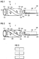
- the length measuring system 1 consists of a magnetic component 100 and a magnetic sensor arrangement 200.
- the magnetic component 100 comprises a permanent magnet 110 and a first magnetically conductive element in the form of a first pole plate 120 and a second magnetically conductive element in the form of a second pole plate 130.
- the two pole plates 120 and 130 are helical, oblong and have a first axial end 122 , 132 and in the second axial end 124, 134 on.
- the pole plates 120, 130 are made of a magnetically good conductive material that is not permanent magnetic.
- the permanent magnet 110 is a two-pole, circular permanent magnet. As shown in Fig. 1 there is a first pole in the upper half and a second pole in the lower half of the permanent magnet 110. Center of the first half of the pole, the first pole plate 120 is disposed on the permanent magnet, for example by gluing. Accordingly, the second pole plate is centered on the second pole 130 arranged. In this way, the two Polbleche 120, 130 are exactly opposite.
- the two pole sheets 120, 130 have a width of approximately between a quarter and a third of the circumference, ie between 90 ° and 120 ° of the circumference.
- each pole piece has a pole or represents it.
- a magnetic field is formed between the two pole plates 120, 130. Due to the helical nature of the pole plates 120, 130, the magnetic field rotates along a length of the component 100 as shown by the arrows 150.
- a non-magnetic carrier material 140 which is referred to below as filling material 140, is arranged peripherally between the pole plates 120, 130.
- the filler 140 may be a plastic, but any non-magnetic material.
- the filling material 140 has at least one thickness that corresponds to the thickness of the pole sheets 120, 130.
- the filling material 140 extends along the length of the component 100, so that the filling material 140 is flush with the first axial end 122, 132 and with the second axial ends 124, 134 of the two pole sheets 120, 130.
- the permanent magnet 110 closes in the illustration according to Fig. 1 the opening of the component 100 at the first axial end and terminates flush with the end of the Polbleche 120, 130 from.
- a thickness of the permanent magnet 110 may be equal to or smaller in diameter.
- the magnetic component 100 is open so that a magnetic sensor assembly 200 can dip, as described below.
- the magnetic sensor arrangement 200 comprises a magnetic sensor 210, an evaluation unit 220 and electrical lines 230.
- the magnetic sensor 210 is arranged perpendicular to a longitudinal axis of the component 100. Both the magnetic sensor 210 and the evaluation unit 220 are surrounded by an electrically insulating housing material 240, for example, encapsulated.
- the housing material is also preferably a non-magnetic material 240, for example plastic.
- the housing material 240 has an outer shape that fits inside the device 100. For example, the housing material 240 is cylindrical when the component 100 is tubular.
- magnetic materials 210 were used for the magnetic sensor 210, the evaluation unit 220 and the electrical leads 230. On this measurement accuracy of the length measuring system 1 can be improved.
- the diameter of the tubular housing material 240 of the sensor arrangement 200 corresponds at most to an inner diameter of the component 100. In this way, the magnetic sensor arrangement 200 can be arranged in the interior of the component 100 and the two components 100, 200 are displaceable relative to one another.
- Fig. 2 shows an alternative embodiment of the length measuring system.
- the magnetic sensor array 200 corresponds to the magnetic sensor array 200 Fig. 1 , Therefore, this will not be explained again in the following.
- the magnetic component 300 consists of two two-pole magnetized magnetic elements 310, 320, that is, two magnetic elements. Both two-pole magnetized magnet elements 310, 320 have a first axial end 312, 322 and a second axial end 314, 324. The mutually facing sides of the two magnetic elements 310, 320 have the respective complementary pole. In this way forms again, as already for Fig. 1 described a rotating magnetic field between the magnetic elements 310, 320 of. This is illustrated by the arrows 350.
- a non-magnetic carrier material 330 is arranged, which is referred to below as filling material 330.
- the properties of the filler 330 correspond those of the filling material 140 from Fig. 1 ,
- the geometry of the magnetic elements 310, 320 corresponds to those of the pole plates 120, 130 and the geometry of the filling material 330 corresponds to that of the filling material 140.
- the first axial end of the component 300 may be open or it may be closed by means of a plastic lid or a lid made of another non-magnetic material. Likewise, the first axial end of the component 300 may be integrally closed with the filling material 330, so that a cup shape for the component 300 results.
- the geometry of the lid preferably corresponds to the geometry described for the permanent magnet 110 Fig. 1 ,
- a step a the magnetic component 100, 300 and the magnetic sensor 210 are moved relative to each other.
- the magnetic sensor 210 detects a magnetic field angle change between the first and second helical magnetically conductive or magnetic members 120, 130 in step b; 310, 320.
- An evaluation of the detected magnetic field angle change in a path signal takes place in step c.
- different magnetic sensors can be used. For example, when rotated by 180 °, as in the Figures 1 and 2 an anisotropic magnetoresistive angle sensor is used. When rotated through 360 °, a GMR angle sensor is preferably used.
- a 2D Hall sensor or another magnetically sensitive sensor can also be used. Important in the magnetic sensors used is only that they can detect a change in the magnetic field, preferably an angle change.
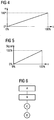
- Fig. 4 shows the change of the magnetic field angle ⁇ as a function of the relative path length s. This is an ideal condition shown. Starting from one of the two axial ends, the angle of the magnetic field is 0 ° and the distance traveled is 0%. If the position of the magnetic sensor 210 inside the magnetic member 100 changes; 300, the angle of the magnetic field also changes. In the examples shown this goes up to a maximum of 180 °. Thus, an angle of 180 ° corresponds to the maximum traveled path length of 100%. If a rotation of 360 ° is used in a GMR angle sensor, then the magnetic field angle of 360 ° corresponds to the path length 100%.
- An exemplary path length is between 50 and 100 mm.
- Fig. 5 shows the relation of the output from the magnetic sensor 210 signals over the path length s. Accordingly, a linear relationship exists between the traveled relative path length s and the signal output by the magnetic sensor 210. Thus, a 0% path length corresponds to a 0% signal, while a 100% path length corresponds to a 100% output signal.
- a signal of 0% correspond to a twist angle of 10 °.
- a signal of 100% may correspond to a twist angle of 170 °.
- the actual twist angle of the magnetically conductive or magnetic elements 120, 130; 310, 320 instead of 180 ° 200 °. Taking into account the just mentioned 10 °, by which the measurement is shortened, there is a measurable angular range of 180 °. In this way, when using an AMR angle sensor, a maximum detection range of the sensor can be optimally utilized.
- a first and a second elongated, helical magnetically conductive or magnetizable element having a first and a provided at the second axial end.
- the provision can be made starting from a strip material by means of stamping and subsequent embossing.
- the magnetically conductive elements are pole plates, so that in each case two identical elements can be produced.
- a tube may be used from which the respective elements are punched out, milled out or lasered out. Further production can take place via compression molding and subsequent sintering process.
- step B the two elements are arranged axisymmetric to each other along a common longitudinal axis.
- a magnetic field can be formed whose angle continuously changes or rotates with respect to the common longitudinal axis along a predeterminable length.
- step C a permanent magnet is arranged adjacent to the first axial ends of the two elements.
- the shape of the permanent magnet was initially described with reference to Fig. 1 described. If there is no encapsulation of the pole sheets in step B, then this can be done together with the permanent magnet in step C, so that the pole sheets do not have to be glued separately to the permanent magnet.
- the order of the above steps is exemplary and can be changed.
- a plastic lid or a lid made of a non-magnetic material can be arranged at the first axial ends of the two magnetic elements. This can be done for example by gluing or encapsulation. In this way, a cup-shaped design of the magnetic component is achieved.
- step D the two elements are arranged on a non-magnetic carrier material.
- a filler material is arranged circumferentially between the elements, so that the magnetic component undergoes an increased mechanical stability.
Claims (17)
- Pièce (100; 300) magnétique pour un système (1) magnétique de mesure de longueur, comprenant :a) un premier élément (120; 310) hélicoïdal, conducteur magnétiquement ou magnétique, ayant une première (122; 312) et une deuxième extrémités (124; 314) axiales, ainsi queb) un deuxième élément (130; 320) hélicoïdal, conducteur magnétiquement ou magnétique, ayant une première (132; 322) et une deuxième extrémités (134; 324) axiales, tandis quec) le premier (120; 310) et le deuxième éléments (130; 320) conducteurs magnétiquement ou magnétiques sont disposés l'un par rapport à l'autre en symétrie axiale suivant un axe (305) longitudinal commun de manière àd) pouvoir constituer, entre le premier (120; 310) et le deuxième éléments (130; 320) conducteurs magnétiquement ou magnétiques, un champ magnétique dont l'angle tourne par rapport à l'axe (305) longitudinal commun continuellement sur une longueur pouvant être donnée à l'avance,caractérisée en ce que
le premier élément conducteur magnétiquement est constitué sous la forme d'une première tôle (120) polaire et le deuxième élément conducteur magnétiquement est constitué sous la forme d'une deuxième tôle (130) polaire, les tôles (120; 130) polaires étant en un matériau bon conducteur magnétiquement, qui n'est pas à magnétisme permanent,
dans laquelle les tôles (120; 130) polaires sont hélicoïdales et oblongues et ont une première extrémité axiale, ainsi qu'une deuxième extrémité (122; 132) axiale et dans laquelle un aimant (110) permanent circulaire à deux pôles ferme l'ouverture de la pièce à la première extrémité (122; 132) axiale et se termine au ras de l'extrémité des tôles (120; 130) polaires et
la pièce (110) magnétique est ouverte à la deuxième extrémité (124; 134) axiale de manière à ce qu'un agencement (200) de capteur magnétique puisse y pénétrer. - Pièce (100) suivant la revendication 1, tandis que la première extrémité (122) du premier élément (120) conducteur magnétiquement et la première extrémité (132) du deuxième élément (130) conducteur magnétiquement sont reliées à un aimant (110) permanent.
- Pièce (100) suivant la revendication 2, tandis que l'aimant (110) permanent est un aimant (110) permanent magnétisé bipolairement, tandis qu'un premier pôle du deuxième aimant (110) permanent magnétisé bipolairement est voisin de la première extrémité (122) axiale du premier élément (120) conducteur magnétiquement et qu'un deuxième pôle de l'aimant (110) permanent magnétisé bipolairement est voisin de la première extrémité (132) axiale du deuxième élément (130) conducteur magnétiquement.
- Pièce (300) suivant la revendication 1, tandis que le premier (310) et le deuxième éléments (320) magnétiques sont magnétisés bipolairement.
- Pièce (100; 300) suivant l'une des revendications précédentes, tandis que le premier (120; 310) et le deuxième éléments (130; 320) conducteurs magnétiquement ou magnétiques sont mis sur un matériau (140; 330) support amagnétique.
- Pièce (100; 300) suivant l'une des revendications précédentes, tandis que le premier (120; 310) et le deuxième éléments (130; 320) conducteurs magnétiquement ou magnétiques sont disposés suivant une symétrie axiale en opposition l'un à l'autre.
- Pièce (100; 300) suivant l'une des revendications précédentes, tandis que le premier (120; 310) et le deuxième éléments (130; 320) conducteurs magnétiquement ou magnétiques sont tordus sur leur longueur entre 45° et 360°, notamment d'environ 180°, autour de l'axe (305) longitudinal commun.
- Système (1) de mesure de longueur comprenant :a) une pièce (100; 300) magnétique suivant l'une des revendications 1 à 7, ainsi queb) un capteur (210) magnétique, qui peut être mis entre le premier (120; 310) et le deuxième (130; 320) éléments, hélicoïdal, conducteur magnétiquement ou magnétique perpendiculairement à l'axe (305) longitudinal commun du premier (120'; 310) et du deuxième éléments (130; 320) conducteurs magnétiquement ou magnétiques, et être relié à une unité (220) d'exploitation, de manière à ce que la pièce (100; 300) magnétique et le capteur (210) magnétique puissent être déplacés l'un par rapport à l'autre.
- Système (1) de mesure de longueur suivant la revendication 8, tandis que le capteur (210) magnétique et l'unité (220) d'exploitation sont entourés d'un matériau (240) d'enveloppe amagnétique d'un diamètre extérieur plus petit qu'un diamètre intérieur de la pièce (100; 300) magnétique.
- Système (1) de mesure de longueur suivant l'une des revendications 8 à 9, tandis que le capteur (210) magnétique est un capteur d'angle magnétorésistif, notamment un capteur d'angle magnétorésistif anisotrope (capteur d'angle AMR) ou un capteur d'angle GMR ou un capteur de Hall 2D.
- Procédé de mesure de longueur par un système (1) de mesure de longueur suivant l'une des revendications 8 à 10, comprenant les stades :a) déplacement (a) de la pièce (100; 300) magnétique et du capteur (210) magnétique l'un par rapport à l'autre,b) détection (b) d'une variation de l'angle du champ magnétique au moyen du capteur (210) magnétique entre le premier (120; 310) et le deuxième éléments (130; 320), hélicoïdal, conducteur magnétiquement ou magnétique etc) exploitation (c) de la variation d'angle du champ magnétique qui a été détectée en un signal de trajet.
- Procédé de fabrication d'une pièce (100; 300) magnétique suivant l'une des revendications 1 à 7, qui a les stades :a) on se procure (A) un premier (120; 310) et un deuxième éléments (130; 320) hélicoïdaux et conducteurs magnétiquement ou magnétisables ayant une première (122; 132; 312; 322) et une deuxième extrémités (124; 134; 314; 324) axiales etb) on met (B) le premier (120; 310) et le deuxième éléments (130; 320) conducteurs magnétiquement ou magnétisables parallèlement l'un à l'autre suivant un axe (305) longitudinal commun, de manière à pouvoir constituer entre le premier (120; 310) et le deuxième éléments (130; 320) conducteurs magnétiquement ou magnétisables un champ magnétique, dont l'angle tourne par rapport à l'axe (305) longitudinal commun continuellement sur une longueur pouvant être donnée à l'avance.
- Procédé de fabrication suivant la revendication 12, tandis que l'on se procure le premier (120; 310) et le deuxième éléments (130; 320) conducteurs magnétiquement ou magnétisables au moyen d'un estampage, d'un découpage, d'un moulage par injection ou d'une découpe par laser.
- Procédé de fabrication suivant la revendication 12, tandis que l'on forme le premier (120; 310) et le deuxième éléments (130; 320) conducteurs magnétiquement ou magnétisables en un matériau de ferrite lié par de la matière plastique dans le procédé de moulage par injection.
- Procédé de fabrication suivant la revendication 12, tandis que l'on forme le premier (120; 310) et le deuxième éléments (130; 320) conducteurs magnétiquement ou magnétisables en une ferrite dure dans un procédé de frittage.
- Procédé de fabrication suivant la revendication 12 à 15, tandis que le premier (120) et le deuxième éléments (130) sont des éléments (120; 130) conducteurs magnétiquement, dans lequel le procédé de fabrication comprend le stade supplémentaire :c) on met (C) un aimant (110) permanent au voisinage de la première extrémité (122; 132) axiale du premier (120) et du deuxième éléments (130) conducteurs magnétiquement, le premier (120) et le deuxième éléments (130) conducteurs magnétiquement étant une première et une deuxième tôles polaires.
- Procédé de fabrication suivant l'une des revendications 12 à 16, qui a le stade supplémentaire :d) on met (D) le premier (120; 310) et le deuxième éléments (130; 320) conducteurs magnétiquement ou magnétisables sur un matériau (140; 330) de support amagnétique.
Applications Claiming Priority (2)
| Application Number | Priority Date | Filing Date | Title |
|---|---|---|---|
| DE102010019077A DE102010019077A1 (de) | 2010-04-30 | 2010-04-30 | Magnetisches Längenmesssystem, Längenmessverfahren sowie Herstellungsverfahren eines magnetischen Längenmesssystems |
| PCT/EP2011/056814 WO2011135063A2 (fr) | 2010-04-30 | 2011-04-29 | Système de mesure de longueur magnétique, procédé de mesure de longueur ainsi que procédé de fabrication d'un système de mesure de longueur magnétique |
Publications (2)
| Publication Number | Publication Date |
|---|---|
| EP2564164A2 EP2564164A2 (fr) | 2013-03-06 |
| EP2564164B1 true EP2564164B1 (fr) | 2016-03-30 |
Family
ID=44118947
Family Applications (1)
| Application Number | Title | Priority Date | Filing Date |
|---|---|---|---|
| EP11721450.2A Active EP2564164B1 (fr) | 2010-04-30 | 2011-04-29 | Système de mesure de longueur magnétique, procédé de mesure de longueur ainsi que procédé de fabrication d'un système de mesure de longueur magnétique |
Country Status (5)
| Country | Link |
|---|---|
| US (1) | US9410788B2 (fr) |
| EP (1) | EP2564164B1 (fr) |
| JP (1) | JP5837048B2 (fr) |
| DE (1) | DE102010019077A1 (fr) |
| WO (1) | WO2011135063A2 (fr) |
Families Citing this family (14)
| Publication number | Priority date | Publication date | Assignee | Title |
|---|---|---|---|---|
| DE102013003270B4 (de) * | 2013-02-27 | 2021-10-28 | Helag Elektronik GmbH | Vorrichtung und Verfahren zum Erfassen einer Linearbewegung |
| US9772200B2 (en) * | 2013-03-15 | 2017-09-26 | Bourns, Inc. | Position measurement using angled collectors |
| US9869566B2 (en) * | 2016-02-12 | 2018-01-16 | Allegro Microsystems, Llc | Angle sensing using differential magnetic measurement and a back bias magnet |
| JP6546565B2 (ja) * | 2016-06-02 | 2019-07-17 | 日本電産サンキョー株式会社 | 直動回転検出器、直動回転検出器ユニットおよび直動回転駆動装置 |
| CN107939813A (zh) * | 2016-10-13 | 2018-04-20 | 珠海格力节能环保制冷技术研究中心有限公司 | 转轴和对转轴进行轴向位移检测的方法 |
| DE102017222677A1 (de) | 2016-12-29 | 2018-07-05 | Robert Bosch Gmbh | Sensoreinrichtung |
| DE212018000387U1 (de) * | 2017-12-27 | 2020-07-29 | Gefran S.P.A. | Kontaktloser linearer Wegaufnehmer |
| FR3082615B1 (fr) | 2018-06-15 | 2020-10-16 | Electricfil Automotive | Methode de determination d'une position angulaire relative entre deux pieces |
| FR3087256B1 (fr) | 2018-10-15 | 2020-10-30 | Electricfil Automotive | Methode et systeme capteur de determination d'une position angulaire relative entre deux pieces, et procede de fabrication d'un corps magnetique |
| DE102019103522A1 (de) * | 2019-02-12 | 2020-08-13 | Novotechnik Messwertaufnehmer OHG | Sensorvorrichtung und Betriebsverfahren hierfür |
| DE102019126987A1 (de) * | 2019-10-08 | 2021-04-08 | Bogen Electronic Gmbh | Messanordnung |
| DE102019216988A1 (de) | 2019-11-05 | 2021-05-06 | Vitesco Technologies GmbH | Positionsmesssystem |
| US11473935B1 (en) | 2021-04-16 | 2022-10-18 | Allegro Microsystems, Llc | System and related techniques that provide an angle sensor for sensing an angle of rotation of a ferromagnetic screw |
| FR3124856B1 (fr) * | 2021-07-05 | 2023-08-04 | Safran Electronics & Defense | Capteur d’usure de garniture de frein |
Family Cites Families (33)
| Publication number | Priority date | Publication date | Assignee | Title |
|---|---|---|---|---|
| US2981885A (en) * | 1958-07-21 | 1961-04-25 | Erick O Schonstedt | Saturable measuring device and magnetic core therefor |
| JPS55122102A (en) | 1979-03-15 | 1980-09-19 | Kyoto Doki Seisakusho:Kk | Device for measuring length |
| JP2554465B2 (ja) | 1985-08-09 | 1996-11-13 | 株式会社 エスジー | アブソリユ−ト位置検出装置 |
| KR900004780B1 (ko) * | 1985-09-13 | 1990-07-05 | 후지쓰 가부시끼가이샤 | 자기(磁氣) 센서를 사용한 위치 검출장치 |
| JPS63231201A (ja) | 1987-03-19 | 1988-09-27 | Fujitsu Ltd | 漏洩磁界型リニアポジシヨナ |
| JPH02222112A (ja) | 1989-02-22 | 1990-09-04 | Hitachi Metals Ltd | マグネットロール |
| JPH0376104A (ja) | 1989-08-17 | 1991-04-02 | Toko Inc | 高周波トランス |
| US5006806A (en) | 1989-03-15 | 1991-04-09 | Schonstedt Instrument Company | Methods and apparatus employing permanent magnets for marking, locating, tracing and identifying hidden objects such as burried fiber optic cables |
| JPH0330255A (ja) | 1989-06-27 | 1991-02-08 | Yuasa Battery Co Ltd | 鉛蓄電池の端子部 |
| JPH0344670A (ja) | 1989-07-12 | 1991-02-26 | Seiko Epson Corp | 現像装置 |
| JPH0376104U (fr) * | 1989-11-29 | 1991-07-30 | ||
| JPH04323501A (ja) | 1991-04-22 | 1992-11-12 | Makome Kenkyusho:Kk | 変位検出装置 |
| JPH0749245A (ja) | 1993-08-04 | 1995-02-21 | Sony Magnescale Inc | 磁気スケール装置 |
| JPH07260408A (ja) | 1994-03-23 | 1995-10-13 | Sony Magnescale Inc | アブソリュート型スケール装置 |
| DE4438715C1 (de) | 1994-10-29 | 1996-05-30 | Inst Mikrostrukturtechnologie | Magnetfeldsensorchip |
| JP2877295B2 (ja) | 1995-04-11 | 1999-03-31 | 三菱重工業株式会社 | 磁石を用いた位置検出器 |
| DE19530386A1 (de) | 1995-08-18 | 1997-02-20 | Philips Patentverwaltung | Positionssensor |
| KR970009683A (ko) | 1995-08-28 | 1997-03-27 | 배순훈 | 회전형 쇼케이스 |
| JPH0972426A (ja) | 1995-09-07 | 1997-03-18 | Nok Corp | 密封装置 |
| JP3030255U (ja) * | 1996-02-21 | 1996-10-22 | 三栄化成株式会社 | 磁気健康具 |
| DE19836599A1 (de) * | 1998-08-13 | 2000-02-17 | Windhorst Beteiligungsgesellsc | Verfahren zur berührungslosen magnetischen Erfassung linearer Relativbewegungen zwischen Dauermagneten und elektronischen Sensoren |
| DE19849613A1 (de) * | 1998-10-28 | 2000-05-04 | Philips Corp Intellectual Pty | Anordnung zur Messung einer relativen linearen Position |
| DE19910636A1 (de) | 1999-03-10 | 2000-09-14 | Inst Mikrostrukturtechnologie | Längenmeßsystem, bestehend aus einem oder mehreren magnetischen Maßstäben |
| WO2001051893A1 (fr) | 2000-01-13 | 2001-07-19 | Continental Teves Ag & Co. Ohg | Capteur de deplacement lineaire et utilisation en tant que dispositif d'actionnement de vehicules motorises |
| DE10010042A1 (de) * | 2000-01-13 | 2001-07-19 | Continental Teves Ag & Co Ohg | Linearer Wegsensor und dessen Verwendung als Betätigungsvorrichtung für Kraftfahrzeuge |
| FR2809808B1 (fr) | 2000-06-06 | 2002-07-19 | Moving Magnet Tech | Capteur de position presentant une insensibilite aux champs exterieurs et aux excentrations |
| DE10162849B4 (de) | 2001-12-20 | 2007-11-29 | Sensitec Gmbh | Längenmesssystem, bei dem ein Massstab relativ zur Position von beabstandeten Längensensoren bewegt wird |
| US7119534B2 (en) | 2002-12-18 | 2006-10-10 | Koninklijke Philips Electronics N.V. | Magnetic position sensor |
| JP4422503B2 (ja) | 2004-02-04 | 2010-02-24 | 学校法人早稲田大学 | 磁性領域の製造装置及び製造方法 |
| JP4571899B2 (ja) | 2005-10-03 | 2010-10-27 | 東京コスモス電機株式会社 | 磁気式変位センサ |
| FR2898189B1 (fr) | 2006-03-02 | 2008-10-17 | Moving Magnet Tech | Capteur de position a direction d'aimantation variable et procede de realisation |
| FR2909170B1 (fr) | 2006-11-28 | 2010-01-29 | Moving Magnet Tech Mmt | Capteur de position linaire ou rotatif a profil d'aimant variable preferentiellement de maniere quasi sinusoidal. |
| FR2923903B1 (fr) | 2007-11-20 | 2010-01-08 | Moving Magnet Tech | Capteur de position magnetique angulaire ou lineaire presentant une insensibilite aux champs exterieurs |
-
2010
- 2010-04-30 DE DE102010019077A patent/DE102010019077A1/de not_active Ceased
-
2011
- 2011-04-29 EP EP11721450.2A patent/EP2564164B1/fr active Active
- 2011-04-29 JP JP2013506673A patent/JP5837048B2/ja active Active
- 2011-04-29 WO PCT/EP2011/056814 patent/WO2011135063A2/fr active Application Filing
- 2011-04-29 US US13/695,520 patent/US9410788B2/en active Active
Also Published As
| Publication number | Publication date |
|---|---|
| WO2011135063A2 (fr) | 2011-11-03 |
| US9410788B2 (en) | 2016-08-09 |
| JP5837048B2 (ja) | 2015-12-24 |
| WO2011135063A3 (fr) | 2012-03-01 |
| US20130113469A1 (en) | 2013-05-09 |
| JP2013527445A (ja) | 2013-06-27 |
| DE102010019077A1 (de) | 2011-11-03 |
| EP2564164A2 (fr) | 2013-03-06 |
Similar Documents
| Publication | Publication Date | Title |
|---|---|---|
| EP2564164B1 (fr) | Système de mesure de longueur magnétique, procédé de mesure de longueur ainsi que procédé de fabrication d'un système de mesure de longueur magnétique | |
| EP2603774B1 (fr) | Dispositif comportant un capteur de couple et un capteur d'angle de rotation | |
| EP3563116B1 (fr) | Capteur de distance | |
| DE102007013755A1 (de) | Indikatorelement für einen magnetischen Drehwinkelgeber | |
| DE102016121671B3 (de) | Positionssensor und Stellgerät mit Positionssensor | |
| EP1662232A1 (fr) | Capteur de position linéaire | |
| EP3936828B1 (fr) | Système de capteur pour un entraînement | |
| DE102005042307A1 (de) | Gurtaufroller | |
| EP2149784A1 (fr) | Système de capteur de trajectoire magnétique | |
| DE19612422C2 (de) | Potentiometereinrichtung mit einem linear verschiebbaren Stellelement und signalerzeugenden Mitteln | |
| EP2492641B1 (fr) | Dispositif de mesure de trajectoire inductif | |
| CH716247B1 (de) | Druckdifferenzaufnehmer für ein Durchflussmessgerät sowie Durchflussmessgerät. | |
| EP3557188B1 (fr) | Bielle magnétisée destinée à la mesure de course | |
| DE102012109598B4 (de) | Induktive Wegmesseinrichtung | |
| EP2492642B1 (fr) | Capteur inductif de déplacement | |
| DE102012000939A1 (de) | Sensoreinheit und Verfahren zur Bestimmung einer Wegstrecke | |
| DE102017202365A1 (de) | Sensoreinrichtung | |
| WO2015074914A2 (fr) | Machine électrique comportant un dispositif de détection de la position d'un rotor | |
| EP1656537B1 (fr) | Capteur de position | |
| EP3561525B1 (fr) | Blindage magnétique d'un capteur à champ parasites interne | |
| CH706043A1 (de) | Winkelsensor. | |
| DE10047939C2 (de) | Induktiver Weggeber | |
| DE10024850C2 (de) | Messanordnung, Messkopf und Verfahren zur Herstellung eines Messkopfes | |
| DE19932726C2 (de) | Vorrichtung zum Abfühlen der Relativposition zweier Teile | |
| EP1886095B1 (fr) | Capteur d'angle de rotation |
Legal Events
| Date | Code | Title | Description |
|---|---|---|---|
| PUAI | Public reference made under article 153(3) epc to a published international application that has entered the european phase |
Free format text: ORIGINAL CODE: 0009012 |
|
| 17P | Request for examination filed |
Effective date: 20121130 |
|
| AK | Designated contracting states |
Kind code of ref document: A2 Designated state(s): AL AT BE BG CH CY CZ DE DK EE ES FI FR GB GR HR HU IE IS IT LI LT LU LV MC MK MT NL NO PL PT RO RS SE SI SK SM TR |
|
| DAX | Request for extension of the european patent (deleted) | ||
| 17Q | First examination report despatched |
Effective date: 20150528 |
|
| GRAP | Despatch of communication of intention to grant a patent |
Free format text: ORIGINAL CODE: EPIDOSNIGR1 |
|
| INTG | Intention to grant announced |
Effective date: 20151015 |
|
| GRAS | Grant fee paid |
Free format text: ORIGINAL CODE: EPIDOSNIGR3 |
|
| GRAA | (expected) grant |
Free format text: ORIGINAL CODE: 0009210 |
|
| AK | Designated contracting states |
Kind code of ref document: B1 Designated state(s): AL AT BE BG CH CY CZ DE DK EE ES FI FR GB GR HR HU IE IS IT LI LT LU LV MC MK MT NL NO PL PT RO RS SE SI SK SM TR |
|
| REG | Reference to a national code |
Ref country code: GB Ref legal event code: FG4D Free format text: NOT ENGLISH |
|
| REG | Reference to a national code |
Ref country code: CH Ref legal event code: EP |
|
| REG | Reference to a national code |
Ref country code: AT Ref legal event code: REF Ref document number: 785885 Country of ref document: AT Kind code of ref document: T Effective date: 20160415 |
|
| REG | Reference to a national code |
Ref country code: IE Ref legal event code: FG4D Free format text: LANGUAGE OF EP DOCUMENT: GERMAN |
|
| REG | Reference to a national code |
Ref country code: FR Ref legal event code: PLFP Year of fee payment: 6 |
|
| REG | Reference to a national code |
Ref country code: DE Ref legal event code: R096 Ref document number: 502011009279 Country of ref document: DE |
|
| REG | Reference to a national code |
Ref country code: LT Ref legal event code: MG4D |
|
| PG25 | Lapsed in a contracting state [announced via postgrant information from national office to epo] |
Ref country code: NO Free format text: LAPSE BECAUSE OF FAILURE TO SUBMIT A TRANSLATION OF THE DESCRIPTION OR TO PAY THE FEE WITHIN THE PRESCRIBED TIME-LIMIT Effective date: 20160630 Ref country code: FI Free format text: LAPSE BECAUSE OF FAILURE TO SUBMIT A TRANSLATION OF THE DESCRIPTION OR TO PAY THE FEE WITHIN THE PRESCRIBED TIME-LIMIT Effective date: 20160330 Ref country code: GR Free format text: LAPSE BECAUSE OF FAILURE TO SUBMIT A TRANSLATION OF THE DESCRIPTION OR TO PAY THE FEE WITHIN THE PRESCRIBED TIME-LIMIT Effective date: 20160701 Ref country code: HR Free format text: LAPSE BECAUSE OF FAILURE TO SUBMIT A TRANSLATION OF THE DESCRIPTION OR TO PAY THE FEE WITHIN THE PRESCRIBED TIME-LIMIT Effective date: 20160330 |
|
| REG | Reference to a national code |
Ref country code: NL Ref legal event code: MP Effective date: 20160330 |
|
| PG25 | Lapsed in a contracting state [announced via postgrant information from national office to epo] |
Ref country code: BE Free format text: LAPSE BECAUSE OF NON-PAYMENT OF DUE FEES Effective date: 20160430 Ref country code: LV Free format text: LAPSE BECAUSE OF FAILURE TO SUBMIT A TRANSLATION OF THE DESCRIPTION OR TO PAY THE FEE WITHIN THE PRESCRIBED TIME-LIMIT Effective date: 20160330 Ref country code: SE Free format text: LAPSE BECAUSE OF FAILURE TO SUBMIT A TRANSLATION OF THE DESCRIPTION OR TO PAY THE FEE WITHIN THE PRESCRIBED TIME-LIMIT Effective date: 20160330 Ref country code: RS Free format text: LAPSE BECAUSE OF FAILURE TO SUBMIT A TRANSLATION OF THE DESCRIPTION OR TO PAY THE FEE WITHIN THE PRESCRIBED TIME-LIMIT Effective date: 20160330 Ref country code: LT Free format text: LAPSE BECAUSE OF FAILURE TO SUBMIT A TRANSLATION OF THE DESCRIPTION OR TO PAY THE FEE WITHIN THE PRESCRIBED TIME-LIMIT Effective date: 20160330 |
|
| PG25 | Lapsed in a contracting state [announced via postgrant information from national office to epo] |
Ref country code: NL Free format text: LAPSE BECAUSE OF FAILURE TO SUBMIT A TRANSLATION OF THE DESCRIPTION OR TO PAY THE FEE WITHIN THE PRESCRIBED TIME-LIMIT Effective date: 20160330 |
|
| PG25 | Lapsed in a contracting state [announced via postgrant information from national office to epo] |
Ref country code: PL Free format text: LAPSE BECAUSE OF FAILURE TO SUBMIT A TRANSLATION OF THE DESCRIPTION OR TO PAY THE FEE WITHIN THE PRESCRIBED TIME-LIMIT Effective date: 20160330 Ref country code: IS Free format text: LAPSE BECAUSE OF FAILURE TO SUBMIT A TRANSLATION OF THE DESCRIPTION OR TO PAY THE FEE WITHIN THE PRESCRIBED TIME-LIMIT Effective date: 20160730 Ref country code: EE Free format text: LAPSE BECAUSE OF FAILURE TO SUBMIT A TRANSLATION OF THE DESCRIPTION OR TO PAY THE FEE WITHIN THE PRESCRIBED TIME-LIMIT Effective date: 20160330 |
|
| PG25 | Lapsed in a contracting state [announced via postgrant information from national office to epo] |
Ref country code: CZ Free format text: LAPSE BECAUSE OF FAILURE TO SUBMIT A TRANSLATION OF THE DESCRIPTION OR TO PAY THE FEE WITHIN THE PRESCRIBED TIME-LIMIT Effective date: 20160330 Ref country code: RO Free format text: LAPSE BECAUSE OF FAILURE TO SUBMIT A TRANSLATION OF THE DESCRIPTION OR TO PAY THE FEE WITHIN THE PRESCRIBED TIME-LIMIT Effective date: 20160330 Ref country code: PT Free format text: LAPSE BECAUSE OF FAILURE TO SUBMIT A TRANSLATION OF THE DESCRIPTION OR TO PAY THE FEE WITHIN THE PRESCRIBED TIME-LIMIT Effective date: 20160801 Ref country code: SK Free format text: LAPSE BECAUSE OF FAILURE TO SUBMIT A TRANSLATION OF THE DESCRIPTION OR TO PAY THE FEE WITHIN THE PRESCRIBED TIME-LIMIT Effective date: 20160330 Ref country code: SM Free format text: LAPSE BECAUSE OF FAILURE TO SUBMIT A TRANSLATION OF THE DESCRIPTION OR TO PAY THE FEE WITHIN THE PRESCRIBED TIME-LIMIT Effective date: 20160330 Ref country code: ES Free format text: LAPSE BECAUSE OF FAILURE TO SUBMIT A TRANSLATION OF THE DESCRIPTION OR TO PAY THE FEE WITHIN THE PRESCRIBED TIME-LIMIT Effective date: 20160330 |
|
| REG | Reference to a national code |
Ref country code: CH Ref legal event code: PL |
|
| REG | Reference to a national code |
Ref country code: DE Ref legal event code: R097 Ref document number: 502011009279 Country of ref document: DE |
|
| REG | Reference to a national code |
Ref country code: IE Ref legal event code: MM4A |
|
| PG25 | Lapsed in a contracting state [announced via postgrant information from national office to epo] |
Ref country code: DK Free format text: LAPSE BECAUSE OF FAILURE TO SUBMIT A TRANSLATION OF THE DESCRIPTION OR TO PAY THE FEE WITHIN THE PRESCRIBED TIME-LIMIT Effective date: 20160330 Ref country code: CH Free format text: LAPSE BECAUSE OF NON-PAYMENT OF DUE FEES Effective date: 20160430 Ref country code: LI Free format text: LAPSE BECAUSE OF NON-PAYMENT OF DUE FEES Effective date: 20160430 |
|
| PLBE | No opposition filed within time limit |
Free format text: ORIGINAL CODE: 0009261 |
|
| STAA | Information on the status of an ep patent application or granted ep patent |
Free format text: STATUS: NO OPPOSITION FILED WITHIN TIME LIMIT |
|
| GBPC | Gb: european patent ceased through non-payment of renewal fee |
Effective date: 20160630 |
|
| 26N | No opposition filed |
Effective date: 20170103 |
|
| REG | Reference to a national code |
Ref country code: FR Ref legal event code: PLFP Year of fee payment: 7 |
|
| PG25 | Lapsed in a contracting state [announced via postgrant information from national office to epo] |
Ref country code: IE Free format text: LAPSE BECAUSE OF NON-PAYMENT OF DUE FEES Effective date: 20160429 Ref country code: SI Free format text: LAPSE BECAUSE OF FAILURE TO SUBMIT A TRANSLATION OF THE DESCRIPTION OR TO PAY THE FEE WITHIN THE PRESCRIBED TIME-LIMIT Effective date: 20160330 Ref country code: GB Free format text: LAPSE BECAUSE OF NON-PAYMENT OF DUE FEES Effective date: 20160630 |
|
| REG | Reference to a national code |
Ref country code: AT Ref legal event code: MM01 Ref document number: 785885 Country of ref document: AT Kind code of ref document: T Effective date: 20160429 |
|
| PG25 | Lapsed in a contracting state [announced via postgrant information from national office to epo] |
Ref country code: AT Free format text: LAPSE BECAUSE OF NON-PAYMENT OF DUE FEES Effective date: 20160429 |
|
| REG | Reference to a national code |
Ref country code: FR Ref legal event code: PLFP Year of fee payment: 8 |
|
| PG25 | Lapsed in a contracting state [announced via postgrant information from national office to epo] |
Ref country code: HU Free format text: LAPSE BECAUSE OF FAILURE TO SUBMIT A TRANSLATION OF THE DESCRIPTION OR TO PAY THE FEE WITHIN THE PRESCRIBED TIME-LIMIT; INVALID AB INITIO Effective date: 20110429 Ref country code: CY Free format text: LAPSE BECAUSE OF FAILURE TO SUBMIT A TRANSLATION OF THE DESCRIPTION OR TO PAY THE FEE WITHIN THE PRESCRIBED TIME-LIMIT Effective date: 20160330 |
|
| PG25 | Lapsed in a contracting state [announced via postgrant information from national office to epo] |
Ref country code: LU Free format text: LAPSE BECAUSE OF NON-PAYMENT OF DUE FEES Effective date: 20160429 Ref country code: MC Free format text: LAPSE BECAUSE OF FAILURE TO SUBMIT A TRANSLATION OF THE DESCRIPTION OR TO PAY THE FEE WITHIN THE PRESCRIBED TIME-LIMIT Effective date: 20160330 Ref country code: MT Free format text: LAPSE BECAUSE OF FAILURE TO SUBMIT A TRANSLATION OF THE DESCRIPTION OR TO PAY THE FEE WITHIN THE PRESCRIBED TIME-LIMIT Effective date: 20160330 Ref country code: MK Free format text: LAPSE BECAUSE OF FAILURE TO SUBMIT A TRANSLATION OF THE DESCRIPTION OR TO PAY THE FEE WITHIN THE PRESCRIBED TIME-LIMIT Effective date: 20160330 Ref country code: TR Free format text: LAPSE BECAUSE OF FAILURE TO SUBMIT A TRANSLATION OF THE DESCRIPTION OR TO PAY THE FEE WITHIN THE PRESCRIBED TIME-LIMIT Effective date: 20160330 |
|
| PG25 | Lapsed in a contracting state [announced via postgrant information from national office to epo] |
Ref country code: BG Free format text: LAPSE BECAUSE OF FAILURE TO SUBMIT A TRANSLATION OF THE DESCRIPTION OR TO PAY THE FEE WITHIN THE PRESCRIBED TIME-LIMIT Effective date: 20160330 |
|
| PG25 | Lapsed in a contracting state [announced via postgrant information from national office to epo] |
Ref country code: AL Free format text: LAPSE BECAUSE OF FAILURE TO SUBMIT A TRANSLATION OF THE DESCRIPTION OR TO PAY THE FEE WITHIN THE PRESCRIBED TIME-LIMIT Effective date: 20160330 |
|
| REG | Reference to a national code |
Ref country code: DE Ref legal event code: R084 Ref document number: 502011009279 Country of ref document: DE |
|
| REG | Reference to a national code |
Ref country code: DE Ref legal event code: R081 Ref document number: 502011009279 Country of ref document: DE Owner name: VITESCO TECHNOLOGIES GMBH, DE Free format text: FORMER OWNER: CONTINENTAL AUTOMOTIVE GMBH, 30165 HANNOVER, DE |
|
| PGFP | Annual fee paid to national office [announced via postgrant information from national office to epo] |
Ref country code: IT Payment date: 20200428 Year of fee payment: 10 |
|
| REG | Reference to a national code |
Ref country code: DE Ref legal event code: R081 Ref document number: 502011009279 Country of ref document: DE Owner name: VITESCO TECHNOLOGIES GMBH, DE Free format text: FORMER OWNER: VITESCO TECHNOLOGIES GMBH, 30165 HANNOVER, DE |
|
| PG25 | Lapsed in a contracting state [announced via postgrant information from national office to epo] |
Ref country code: IT Free format text: LAPSE BECAUSE OF NON-PAYMENT OF DUE FEES Effective date: 20200429 |
|
| P01 | Opt-out of the competence of the unified patent court (upc) registered |
Effective date: 20230530 |
|
| PGFP | Annual fee paid to national office [announced via postgrant information from national office to epo] |
Ref country code: FR Payment date: 20230420 Year of fee payment: 13 Ref country code: DE Payment date: 20230430 Year of fee payment: 13 |