EP2564164B1 - Magnetic length measuring system, length measuring method and method for producing a magnetic length measuring system - Google Patents
Magnetic length measuring system, length measuring method and method for producing a magnetic length measuring system Download PDFInfo
- Publication number
- EP2564164B1 EP2564164B1 EP11721450.2A EP11721450A EP2564164B1 EP 2564164 B1 EP2564164 B1 EP 2564164B1 EP 11721450 A EP11721450 A EP 11721450A EP 2564164 B1 EP2564164 B1 EP 2564164B1
- Authority
- EP
- European Patent Office
- Prior art keywords
- magnetic
- magnetically conductive
- elements
- component
- sensor
- Prior art date
- Legal status (The legal status is an assumption and is not a legal conclusion. Google has not performed a legal analysis and makes no representation as to the accuracy of the status listed.)
- Active
Links
Images
Classifications
-
- G—PHYSICS
- G01—MEASURING; TESTING
- G01B—MEASURING LENGTH, THICKNESS OR SIMILAR LINEAR DIMENSIONS; MEASURING ANGLES; MEASURING AREAS; MEASURING IRREGULARITIES OF SURFACES OR CONTOURS
- G01B7/00—Measuring arrangements characterised by the use of electric or magnetic techniques
- G01B7/02—Measuring arrangements characterised by the use of electric or magnetic techniques for measuring length, width or thickness
- G01B7/04—Measuring arrangements characterised by the use of electric or magnetic techniques for measuring length, width or thickness specially adapted for measuring length or width of objects while moving
- G01B7/042—Measuring arrangements characterised by the use of electric or magnetic techniques for measuring length, width or thickness specially adapted for measuring length or width of objects while moving for measuring length
- G01B7/046—Measuring arrangements characterised by the use of electric or magnetic techniques for measuring length, width or thickness specially adapted for measuring length or width of objects while moving for measuring length using magnetic means
-
- G—PHYSICS
- G01—MEASURING; TESTING
- G01D—MEASURING NOT SPECIALLY ADAPTED FOR A SPECIFIC VARIABLE; ARRANGEMENTS FOR MEASURING TWO OR MORE VARIABLES NOT COVERED IN A SINGLE OTHER SUBCLASS; TARIFF METERING APPARATUS; MEASURING OR TESTING NOT OTHERWISE PROVIDED FOR
- G01D5/00—Mechanical means for transferring the output of a sensing member; Means for converting the output of a sensing member to another variable where the form or nature of the sensing member does not constrain the means for converting; Transducers not specially adapted for a specific variable
- G01D5/12—Mechanical means for transferring the output of a sensing member; Means for converting the output of a sensing member to another variable where the form or nature of the sensing member does not constrain the means for converting; Transducers not specially adapted for a specific variable using electric or magnetic means
- G01D5/14—Mechanical means for transferring the output of a sensing member; Means for converting the output of a sensing member to another variable where the form or nature of the sensing member does not constrain the means for converting; Transducers not specially adapted for a specific variable using electric or magnetic means influencing the magnitude of a current or voltage
- G01D5/142—Mechanical means for transferring the output of a sensing member; Means for converting the output of a sensing member to another variable where the form or nature of the sensing member does not constrain the means for converting; Transducers not specially adapted for a specific variable using electric or magnetic means influencing the magnitude of a current or voltage using Hall-effect devices
- G01D5/145—Mechanical means for transferring the output of a sensing member; Means for converting the output of a sensing member to another variable where the form or nature of the sensing member does not constrain the means for converting; Transducers not specially adapted for a specific variable using electric or magnetic means influencing the magnitude of a current or voltage using Hall-effect devices influenced by the relative movement between the Hall device and magnetic fields
Definitions
- the present invention relates to a magnetic component for a magnetic length measuring system, a magnetic length measuring system, a length measuring method with a magnetic length measuring system, and a manufacturing method of a magnetic component for a magnetic length measuring system.
- Magnetically based methods for linear displacement measurement have a high cross-sensitivity with regard to changes in distance, changes in temperature and magnetic field strength compared to other methods. Therefore, there are always considerations to realize a linear displacement measurement with a magnetoresistive angle sensor. However, there are currently no cost-effective and the accuracy requirements appropriate solution concepts. Furthermore, known stray field based measuring systems are sensitive to external disturbance magnetic fields.
- An arrangement for measuring a relative linear position is off EP 0 997 706 B1 known.
- the arrangement serves to measure a relative linear position between a sensor and a magnetic body, wherein the position relative to each other in a predetermined direction is linearly variable.
- the sensor is designed as a magnetoresistive angle sensor and a magnetic strip is provided as a magnetic body.
- the magnetic strip has a magnetic pole pair and a magnetic field extending over its length at a varying angle, which can be illustrated by corresponding magnetic field lines. In this way, the angle of the magnetoresistive angle sensor penetrating the magnetic field from the relative position of the magnetoresistive angle sensor with respect to the magnetic Strip dependent. From the output signal of the magnetoresistive angle sensor, the respective relative position can be determined.
- the DE 100 10 042 A1 discloses a linear displacement sensor and its use as an actuator for motor vehicles.
- a linear transducer for motor vehicles is shown which comprises a displaceable element and a stator.
- the displaceable element has a magnetic encoder.
- the stator sensor modules are connected stationary, which operate on the AMR principle, the GMR principle or the Hall principle.
- the displaceable element is guided by a bearing connected to the stator, which encompasses and axially guides the displaceable element.
- the sensor module (s) are stationary with the stator.
- the longitudinal axis of the displaceable element or the field generating means are positively connected to the displaceable element.
- the EP 0 212 406 A2 discloses an apparatus for detecting an absolute linear position.
- a first repetitive raster varies in the longitudinal direction with a predetermined pitch, and a second pitch varies in the longitudinal direction with a pitch different from the first pitch. Both patterns are formed on the surface of a bar.
- a detector head region is disposed proximate to this rod, with the detector head region individually responsive to the first and second patterns, and the changes associated with the linear position of the rod.
- a length measuring system which consists of one or more magnetic scales.
- the magnetization direction lies in the plane of its perpendicular to the measuring direction cross-section and forms a magnetization pattern.
- this magnetization of the cross section is homogeneous. With progression in the measuring direction, the magnetization pattern is increasingly twisted in relation to that at the beginning of the scale.
- the magnetization leads to a magnetic field, the direction of which is also constantly being rotated further as the measurement direction progresses.
- the angle of the magnetic field present in the respective position is determined and can be unambiguously assigned to the position for many different variants of the length measuring system.
- the scale used is a solid bar magnet with a rotating magnetization.
- the sensor is located at a predetermined distance parallel to the longitudinal axis of the bar magnet.
- the sensor is therefore arranged at a distance to the bar magnet so as to be moved in a range of the maximum strength of the stray magnetic field of the bar magnet.
- a disadvantage of the prior art arrangements is that magnetization must be realized with a varying angle along the length of the magnet.
- the arrangement according to the first example has never been realized due to the magnetization which can not be carried out with known means.
- a further disadvantage is that the accuracy with the arrangements according to the prior art depends on the field homogeneity in the stray field and thus on the distance between sensor and magnet. So there is an optimum on an axis parallel to the longitudinal axis of the magnet for the sensor on which a measurement must be performed. Accordingly, the prior art arrangements operate with a magnetically inhomogeneous stray field outside the magnet. For this reason, the arrangements are very sensitive to external influences, in particular external disturbing magnetic fields. This can lead to a further inaccuracy of the measurement.
- the bar magnet must generate correspondingly higher magnetic field strengths for safe saturation of the sensors.
- a rotation of the bar magnet according to DE 199 10 636 A1 over time lead to the fact that no more accurate measurement is given.
- the bar magnet may detach from a fixture over time and rotate along its longitudinal axis.
- Another disadvantage of the arrangement is that the bar magnet with the rotating magnetization is costly.
- the object of the present invention is therefore to optimize a magnetic length measuring system in comparison to the prior art and to provide a corresponding one Length measuring method and method of manufacturing a magnetic component of a length measuring system.
- a magnetic component for a magnetic length measuring system comprises a first helical, magnetically conductive or magnetic element having a first and a second axial end and a second helical, magnetically conductive or magnetic element having a first and a second axial end, while the first and the second magnetically conductive or magnetic element along a common longitudinal axis are arranged axisymmetric to each other, so that between the first and the second magnetically conductive or magnetic element, a magnetic field can be formed, the angle of which rotates continuously with respect to the common longitudinal axis along a predetermined length.
- the magnetic component is used in the magnetic length measuring system together with a magnetic sensor which is guided between the first and the second magnetically conductive or magnetic element. Ideally, a homogeneous magnetic field is formed between the first and the second magnetically conductive or magnetic element.
- the region between the first and the second magnetically conductive or magnetic element is also referred to below as the interior of the magnetic component.
- the magnetic field rotates about the longitudinal axis of the interior of the magnetic Component when viewed in the longitudinal direction.
- the rotating magnetic field between the two magnetically conductive or magnetic elements is thus achieved solely on the basis of the geometry and the arrangement of the two elements.
- the helical nature of the elements and their arrangement about the common longitudinal axis have the further consequence that the magnetic component, for example, has a tubular design.
- the two magnetic elements are thus arranged at a predeterminable distance from the common longitudinal axis outside on an imaginary, for example, tubular form around the common longitudinal axis, whereby the above-mentioned component interior is formed. This applies at least to a region of the component in which the magnetically conductive or magnetic elements are helical or in the form of a helix.
- An exact configuration of the two magnetically conductive or magnetic elements in terms of width, thickness and length depends on the overall proportions of the magnetic component and the respective application.
- the proportions of the two magnetically conductive or magnetic elements are chosen so that a maximum magnetic field concentration between the two elements is achieved.
- the two magnetically conductive or magnetic elements extend circumferentially over a quarter or a third (90 ° or 120 °) of the imaginary circumference around the common longitudinal axis.
- a length of the two magnetically conductive or magnetic elements is for example between 20 mm and 200 mm.
- the two magnetically conductive or magnetic elements are matched to one another, that is to say they preferably have the same width, the same length and the same thickness, and are therefore therefore axisymmetric.
- the two elements are parallel to each other.
- the two magnetically conductive or magnetic elements are elongated.
- the magnetically conductive or magnetic elements can also have a straight section in an initial or an end region.
- Straight means that the elements are parallel to each other and to the common longitudinal axis. This straight section is preferably located at one of the axial ends. In this straight region, the elements may continue to have the roundness of the tubular component or they may be flattened.
- the common longitudinal axis is preferably a straight line.
- the common longitudinal axis can also be a curvilinear longitudinal axis. In this way, a curved shape of the magnetic component is achieved, if required for a specific application.
- the magnetic sensor is also guided between the two magnetic elements, but along or adjacent to the curvilinear longitudinal axis.
- An advantage of the magnetic component according to the invention is that, during operation in a length measuring system, the magnetic sensor is guided in an interior of the component. In this way, the magnetic sensor is effectively shielded from external interference magnetic fields. Furthermore, the sensor is in a homogeneous magnetic field, so that it can be arranged arbitrarily in the interior and does not have to be arranged along the common longitudinal axis of the magnetic elements. In addition, the magnetic field strength remains largely constant over the measuring length.
- the cost of the magnetic component is lower because there is no rotary magnetization as in the prior art. Since the rotation of the magnetic field is caused solely by the helicity of the magnetically conductive or magnetic elements, the magnetic component according to the invention enables accurate measurement due to the homogeneous magnetic field. Likewise, a cheaper production compared to the prior art can be realized.
- a disadvantage of the arrangement compared to the prior art is to mention that when operating in a length measuring system twice the length of the measuring path for installation is required, unless the magnetic sensor is operated with a flexible electrical connection.
- the magnetoresistive angle sensor and the magnet are arranged parallel to each other.
- the axial length of the magnet corresponds approximately to the maximum measuring path and the maximum space required in the axial direction.
- the magnetic sensor is disposed inside the magnetic member. In an exemplary extreme case, in a first state, the sensor is located at the first axial end of the component. Now, the position of the component and the magnetic sensor changes relative to each other and in a second state, the sensor is located at the second axial end of the component. Thus, there is a larger space requirement in the axial direction. This space requirement is for example twice the axial length of the magnetic component.
- the first end of the first magnetically conductive element and the first end of the second magnetically conductive element are connected to a permanent magnet.
- the two magnetically conductive elements are in particular pole plates.
- the pole plates are preferably made of an iron material. However, any magnetic material that is not permanent magnetic can be used.
- the first axial ends of the two magnetically conductive elements are arranged adjacent to the permanent magnet.
- the permanent magnet can be, for example, two single-pole permanent magnets. Alternatively, it may also be a two-pole permanent magnet, whereupon will be discussed in more detail later. In each case one pole of the permanent magnet is assigned to a magnetically conductive element, that is to say a pole plate.
- a gap may be present between the two pole plates and the permanent magnet (s), the pole plates being intended to be arranged as close as possible to the respective permanent magnet.
- the pole plates are glued to the permanent magnet or arranged by extrusion coating.
- the one or more permanent magnets may be circular or cuboid. If the permanent magnet is cuboid, then the magnetically conductive element preferably has the flattened straight region described above. A connection between the permanent magnets and the respective pole plate takes place so that a maximum magnetic field transmission between the permanent magnet and the pole plates can take place. For this reason, the permanent magnet is arranged adjacent to the respective pole plate, for example, at the first axial end of the component in the interior of the component.
- the permanent magnet is a two-pole permanent magnet, while a first pole of the two-pole permanent magnet is adjacent to the first axial end of the first magnetically conductive element and a second pole of the two-pole permanent magnet is adjacent to the first axial end of the second magnetically conductive element ,
- the two-pole permanent magnet may, as mentioned above, be circular or cuboid.
- the two-pole permanent magnet is in particular made of a ferromagnetic material and is inserted into the opening at the first axial end or partially disposed therein.
- the permanent magnet is flush with the first axial end of the first and second magnetic elements.
- the permanent magnet can also only externally disposed adjacent to the first axial end of the magnetic member. An advantage of this arrangement is that the component is closed on this side and a large volume for the permanent magnet is available.
- the first and the second magnetic element are magnetized bipolar.
- the two-pole magnetic elements allow, in contrast to the use of two pole plates with a permanent magnet, that the component is open at both ends.
- one end of the component may be closed by means of a plastic lid.
- any non-magnetic material may be used to close the component at its first axial end.
- the shapes and arrangement of this lid correspond to those described above for the permanent magnet. Since no permanent magnet is used at one axial end of the component in this arrangement, no stray fields caused by the permanent magnet occur at the first end of the magnetic component in this arrangement. The measurement is thus further specified.
- the magnetic component comprises a non-magnetic carrier material on which the first and the second magnetically conductive or magnetic element is arranged.
- the magnetic member is closed at one axial end by means of a plastic cover or a permanent magnet or in another manner, the pole sheets or the magnetic elements may be arranged thereon. Between or next to the two magnetic elements circumferentially no additional material is required. Thus, air may be present circumferentially between or adjacent to the two elements.
- the non-magnetic carrier material is located between or next to the magnetically conductive or magnetic elements.
- This is a non-magnetic material such as aluminum.
- the preferred carrier material is a plastic. In this way, the mechanical stability of the magnetic component is further increased.
- the lid can be made in one piece from this carrier material to complete the first end.
- the magnetic component is therefore designed pot-shaped or tubular.
- the first and the second magnetically conductive or magnetic element are arranged opposite one another axially symmetrical.
- the circumferential distance between the two elements is thus always the same and axisymmetric. In this way, a particularly accurate measurement can be realized.
- first and the second magnetically conductive or magnetic element are twisted along their length between 45 ° and 360 °, in particular by approximately 180 °, about the common longitudinal axis.
- the so-called twist angle depends in particular on the type of magnetic sensor used, which will be discussed in detail later.
- the rotation depends on the length and the desired accuracy of the measurement.
- a length measuring system comprises a magnetic component according to the invention and a magnetic sensor which can be arranged between the first and the second helical magnetically conductive or magnetic element perpendicular to the common longitudinal axis of the first and the second magnetically conductive or magnetic element and is connected to an evaluation unit, so that the magnetic component and the magnetic sensor are movable relative to each other.
- the magnetic sensor is located in an interior of the magnetic component.
- the magnetic component and the magnetic sensor become relative during a measurement moved to each other.
- each sensor is suitable, which can detect an angular change of a magnetic field.
- the magnetic sensor and the evaluation unit are surrounded by a non-magnetic housing material having an outer diameter which is smaller than an inner diameter of the magnetic component.
- the magnetic sensor and the evaluation unit can be encapsulated by a non-magnetic housing material. This may be, for example, plastic.
- the magnetic sensor, the evaluation unit and the electrical lines used were made of a non-magnetic material. In this way, a falsification of the measurement due to interference fields can be minimized.
- the diameter of the housing material surrounding the magnetic sensor and the evaluation unit may be selected such that a predeterminable gap is present between the outer diameter of the housing material surrounding the magnetic sensor and the inner diameter of the tubular component.
- a predeterminable gap is present between the outer diameter of the housing material surrounding the magnetic sensor and the inner diameter of the tubular component.
- the magnetic sensor is a magnetoresistive angle sensor, in particular an anisotropic magnetoresistive angle sensor (AMR angle sensor) or a giant magnetoresistive angle sensor (GMR angle sensor), or a 2D Hall sensor.
- AMR angle sensor anisotropic magnetoresistive angle sensor
- GMR angle sensor giant magnetoresistive angle sensor
- 2D Hall sensor a 2D Hall sensor.
- the rotation of the two magnetically conductive or magnetic elements along the common longitudinal axis is a maximum of approximately 180 °.
- the rotation is chosen in particular so that the magnetic sensor can detect a true angular rotation of 180 ° in a later measurement method.
- an actual twist of the two magnetically conductive or magnetic elements can result in about 200 °, since the magnetic sensor can not measure exactly from beginning to end.
- the first and the last 10 ° rotation with the magnetic sensor can not sensibly be detected, in particular due to a permanent magnet arranged adjacent to the first axial end.
- the increased actual twist may also result from calibration operations.
- the actual rotation is for example 180 °, while the rotation is measured only in a range between 10 ° and 170 °.
- the measuring range of the available distance is reduced with unchanged length of the component.
- the rotation of the two magnetically conductive or magnetic elements in a GMR angle sensor, about 360 °. Again, the actual rotation can be at 380 ° to obtain a maximum detectable rotation of 360 °.
- a length measuring method with a length measuring system comprises the steps of: moving the magnetic component and the magnetic sensor relative to each other, detecting a magnetic field angle change by means of the magnetic sensor between the first and the second helical magnetically conductive or magnetic element and evaluating the detected magnetic field angle change in a path signal.
- the length measuring method according to the invention has the advantages of the magnetic component described above and the length measuring system described above.
- the magnetic sensor is arranged inside the magnetic component and there is a relative movement of the component to the magnetic sensor instead. Due to this arrangement, as already stated above, the double path length for the measuring device is required, unless there is a flexible electrical connection.
- the magnetic component is moved while the magnetic sensor with the evaluation unit is arranged stationary.
- the electrical lines of the magnetic sensor and the evaluation unit can be fixed and need not be made flexible. This simplifies the structure of the arrangement.
- a magnetic field rotation is detected, as described above. This is in particular a centric angle change of the magnetic field.
- the magnetic sensor transmits electrical signals to the evaluation unit, which can determine at least one angular rotation of the signals, preferably an absolute angle.
- a manufacturing method of a magnetic component according to the invention comprises the steps of providing first and second helical and magnetically conductive or magnetizable elements having first and second axial ends and disposing the first and second magnetically conductive or magnetizable elements parallel to one another along a common longitudinal axis such that between the first and the second magnetically conductive or magnetizable element a magnetic field can be formed, the angle of which with respect to the common Longitudinal axis along a predetermined length continuously rotates.
- the magnetic component according to the invention can be produced, which has the advantages mentioned above. Provision of the magnetically conductive or magnetizable elements can be effected in the case of an initial strip material by means of embossing.
- the basic geometry of the magnetically conductive or magnetizable elements has previously been punched out, for example. In the production of the magnetically conductive or magnetizable elements from a tube, this can be done by milling, laser cutting or punching. When using Polblechen each the same element is produced.
- two identical magnetic elements can be produced, but these are magnetized differently poled, since in the subsequent use in each case two different poles must show in the direction of the common longitudinal axis. This is especially necessary when using two-pole magnetic elements.
- the provision of the first and second magnetizable or magnetic element therefore takes place by means of embossing, stamping, injection molding or laser cutting.
- first and the second magnetically conductive or magnetizable element made of plastic-bonded ferrite material is injection molded.
- the first and second magnetically conductive or magnetizable hard ferrite members may be formed in a sintering process.
- the manufacturing method comprising the step of disposing a permanent magnet adjacent the first axial end of the first and second magnetically conductive elements, wherein the first and second magnetically conductive elements are first and second pole plates.
- the production method comprises the further step: arranging the first and the second magnetically conductive or magnetizable element on a non-magnetic carrier material.
- the component is circumferentially closed, whereby a mechanical stability of the component is increased.
- the magnetically conductive or magnetizable elements can be overmolded with plastic, glued into a plastic tube or clipped into place. If a permanent magnet is used, then this can likewise be encapsulated with, so that an adhesion of the pole plates to each pole of the permanent magnet is not additionally required, but can still be performed.
- the magnetic length measuring system is used for linear displacement measurement.
- the linear displacement measurement for motor vehicles can be used for example for measuring the compression travel between body and chassis or wheel.
- the positions of linear actuators can be determined.
- the length measuring system 1 consists of a magnetic component 100 and a magnetic sensor arrangement 200.
- the magnetic component 100 comprises a permanent magnet 110 and a first magnetically conductive element in the form of a first pole plate 120 and a second magnetically conductive element in the form of a second pole plate 130.
- the two pole plates 120 and 130 are helical, oblong and have a first axial end 122 , 132 and in the second axial end 124, 134 on.
- the pole plates 120, 130 are made of a magnetically good conductive material that is not permanent magnetic.
- the permanent magnet 110 is a two-pole, circular permanent magnet. As shown in Fig. 1 there is a first pole in the upper half and a second pole in the lower half of the permanent magnet 110. Center of the first half of the pole, the first pole plate 120 is disposed on the permanent magnet, for example by gluing. Accordingly, the second pole plate is centered on the second pole 130 arranged. In this way, the two Polbleche 120, 130 are exactly opposite.
- the two pole sheets 120, 130 have a width of approximately between a quarter and a third of the circumference, ie between 90 ° and 120 ° of the circumference.
- each pole piece has a pole or represents it.
- a magnetic field is formed between the two pole plates 120, 130. Due to the helical nature of the pole plates 120, 130, the magnetic field rotates along a length of the component 100 as shown by the arrows 150.
- a non-magnetic carrier material 140 which is referred to below as filling material 140, is arranged peripherally between the pole plates 120, 130.
- the filler 140 may be a plastic, but any non-magnetic material.
- the filling material 140 has at least one thickness that corresponds to the thickness of the pole sheets 120, 130.
- the filling material 140 extends along the length of the component 100, so that the filling material 140 is flush with the first axial end 122, 132 and with the second axial ends 124, 134 of the two pole sheets 120, 130.
- the permanent magnet 110 closes in the illustration according to Fig. 1 the opening of the component 100 at the first axial end and terminates flush with the end of the Polbleche 120, 130 from.
- a thickness of the permanent magnet 110 may be equal to or smaller in diameter.
- the magnetic component 100 is open so that a magnetic sensor assembly 200 can dip, as described below.
- the magnetic sensor arrangement 200 comprises a magnetic sensor 210, an evaluation unit 220 and electrical lines 230.
- the magnetic sensor 210 is arranged perpendicular to a longitudinal axis of the component 100. Both the magnetic sensor 210 and the evaluation unit 220 are surrounded by an electrically insulating housing material 240, for example, encapsulated.
- the housing material is also preferably a non-magnetic material 240, for example plastic.
- the housing material 240 has an outer shape that fits inside the device 100. For example, the housing material 240 is cylindrical when the component 100 is tubular.
- magnetic materials 210 were used for the magnetic sensor 210, the evaluation unit 220 and the electrical leads 230. On this measurement accuracy of the length measuring system 1 can be improved.
- the diameter of the tubular housing material 240 of the sensor arrangement 200 corresponds at most to an inner diameter of the component 100. In this way, the magnetic sensor arrangement 200 can be arranged in the interior of the component 100 and the two components 100, 200 are displaceable relative to one another.
- Fig. 2 shows an alternative embodiment of the length measuring system.
- the magnetic sensor array 200 corresponds to the magnetic sensor array 200 Fig. 1 , Therefore, this will not be explained again in the following.
- the magnetic component 300 consists of two two-pole magnetized magnetic elements 310, 320, that is, two magnetic elements. Both two-pole magnetized magnet elements 310, 320 have a first axial end 312, 322 and a second axial end 314, 324. The mutually facing sides of the two magnetic elements 310, 320 have the respective complementary pole. In this way forms again, as already for Fig. 1 described a rotating magnetic field between the magnetic elements 310, 320 of. This is illustrated by the arrows 350.
- a non-magnetic carrier material 330 is arranged, which is referred to below as filling material 330.
- the properties of the filler 330 correspond those of the filling material 140 from Fig. 1 ,
- the geometry of the magnetic elements 310, 320 corresponds to those of the pole plates 120, 130 and the geometry of the filling material 330 corresponds to that of the filling material 140.
- the first axial end of the component 300 may be open or it may be closed by means of a plastic lid or a lid made of another non-magnetic material. Likewise, the first axial end of the component 300 may be integrally closed with the filling material 330, so that a cup shape for the component 300 results.
- the geometry of the lid preferably corresponds to the geometry described for the permanent magnet 110 Fig. 1 ,
- a step a the magnetic component 100, 300 and the magnetic sensor 210 are moved relative to each other.
- the magnetic sensor 210 detects a magnetic field angle change between the first and second helical magnetically conductive or magnetic members 120, 130 in step b; 310, 320.
- An evaluation of the detected magnetic field angle change in a path signal takes place in step c.
- different magnetic sensors can be used. For example, when rotated by 180 °, as in the Figures 1 and 2 an anisotropic magnetoresistive angle sensor is used. When rotated through 360 °, a GMR angle sensor is preferably used.
- a 2D Hall sensor or another magnetically sensitive sensor can also be used. Important in the magnetic sensors used is only that they can detect a change in the magnetic field, preferably an angle change.
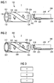
- Fig. 4 shows the change of the magnetic field angle ⁇ as a function of the relative path length s. This is an ideal condition shown. Starting from one of the two axial ends, the angle of the magnetic field is 0 ° and the distance traveled is 0%. If the position of the magnetic sensor 210 inside the magnetic member 100 changes; 300, the angle of the magnetic field also changes. In the examples shown this goes up to a maximum of 180 °. Thus, an angle of 180 ° corresponds to the maximum traveled path length of 100%. If a rotation of 360 ° is used in a GMR angle sensor, then the magnetic field angle of 360 ° corresponds to the path length 100%.
- An exemplary path length is between 50 and 100 mm.
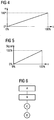
- Fig. 5 shows the relation of the output from the magnetic sensor 210 signals over the path length s. Accordingly, a linear relationship exists between the traveled relative path length s and the signal output by the magnetic sensor 210. Thus, a 0% path length corresponds to a 0% signal, while a 100% path length corresponds to a 100% output signal.
- a signal of 0% correspond to a twist angle of 10 °.
- a signal of 100% may correspond to a twist angle of 170 °.
- the actual twist angle of the magnetically conductive or magnetic elements 120, 130; 310, 320 instead of 180 ° 200 °. Taking into account the just mentioned 10 °, by which the measurement is shortened, there is a measurable angular range of 180 °. In this way, when using an AMR angle sensor, a maximum detection range of the sensor can be optimally utilized.
- a first and a second elongated, helical magnetically conductive or magnetizable element having a first and a provided at the second axial end.
- the provision can be made starting from a strip material by means of stamping and subsequent embossing.
- the magnetically conductive elements are pole plates, so that in each case two identical elements can be produced.
- a tube may be used from which the respective elements are punched out, milled out or lasered out. Further production can take place via compression molding and subsequent sintering process.
- step B the two elements are arranged axisymmetric to each other along a common longitudinal axis.
- a magnetic field can be formed whose angle continuously changes or rotates with respect to the common longitudinal axis along a predeterminable length.
- step C a permanent magnet is arranged adjacent to the first axial ends of the two elements.
- the shape of the permanent magnet was initially described with reference to Fig. 1 described. If there is no encapsulation of the pole sheets in step B, then this can be done together with the permanent magnet in step C, so that the pole sheets do not have to be glued separately to the permanent magnet.
- the order of the above steps is exemplary and can be changed.
- a plastic lid or a lid made of a non-magnetic material can be arranged at the first axial ends of the two magnetic elements. This can be done for example by gluing or encapsulation. In this way, a cup-shaped design of the magnetic component is achieved.
- step D the two elements are arranged on a non-magnetic carrier material.
- a filler material is arranged circumferentially between the elements, so that the magnetic component undergoes an increased mechanical stability.
Description
Die vorliegende Erfindung betrifft ein magnetisches Bauteil für ein magnetisches Längenmesssystem, ein magnetisches Längenmesssystem, ein Längenmessverfahren mit einem magnetischen Längenmesssystem sowie ein Herstellungsverfahren eines magnetischen Bauteils für ein magnetisches Längenmesssystem.The present invention relates to a magnetic component for a magnetic length measuring system, a magnetic length measuring system, a length measuring method with a magnetic length measuring system, and a manufacturing method of a magnetic component for a magnetic length measuring system.
Es sind unterschiedliche Verfahren zur Realisierung von linearen Wegmessungen bekannt. Magnetisch basierte Verfahren zur linearen Wegmessung weisen eine im Vergleich zu anderen Verfahren hohe Querempfindlichkeit im Hinblick auf Abstandsänderungen, Temperatur- und Magnetfeldstärkeänderungen auf. Daher gibt es immer wieder Überlegungen, eine lineare Wegmessung mit einem magnetoresistiven Winkelsensor zu realisieren. Allerdings liegen derzeit keine kostengünstigen und den Genauigkeitsanforderungen entsprechenden Lösungskonzepte vor. Weiterhin sind bekannte Streufeld basierte Messsysteme empfindlich gegenüber äußeren Störmagnetfeldern.Different methods for the realization of linear displacement measurements are known. Magnetically based methods for linear displacement measurement have a high cross-sensitivity with regard to changes in distance, changes in temperature and magnetic field strength compared to other methods. Therefore, there are always considerations to realize a linear displacement measurement with a magnetoresistive angle sensor. However, there are currently no cost-effective and the accuracy requirements appropriate solution concepts. Furthermore, known stray field based measuring systems are sensitive to external disturbance magnetic fields.
Eine Anordnung zur Messung einer relativen linearen Position ist aus
Die
Die
Aus
Bei dem verwendeten Maßstab handelt es sich um einen massiven Stabmagneten mit einer rotierenden Magnetisierung. Der Sensor befindet sich in einem vorgegebenen Abstand parallel zu der Längsachse des Stabmagneten. Der Sensor ist daher in einer solchen Entfernung zu dem Stabmagneten angeordnet, dass er in einem Bereich der maximalen Stärke des magnetischen Streufelds des Stabmagneten bewegt wird.The scale used is a solid bar magnet with a rotating magnetization. The sensor is located at a predetermined distance parallel to the longitudinal axis of the bar magnet. The sensor is therefore arranged at a distance to the bar magnet so as to be moved in a range of the maximum strength of the stray magnetic field of the bar magnet.
Ein Nachteil der Anordnungen gemäß Stand der Technik ist, dass eine Magnetisierung mit sich änderndem Winkel entlang der Länge des Magneten realisiert werden muss. Insbesondere die Anordnung gemäß dem ersten Beispiel wurde aufgrund der mit bekannten Mitteln nicht durchführbaren Magnetisierung nie realisiert.A disadvantage of the prior art arrangements is that magnetization must be realized with a varying angle along the length of the magnet. In particular, the arrangement according to the first example has never been realized due to the magnetization which can not be carried out with known means.
Bei der Verwendung eines Stabmagneten, wie in
Ein weiterer Nachteil ist, dass die Genauigkeit mit den Anordnungen gemäß Stand der Technik von der Feldhomogenität im Streufeld und somit von dem Abstand zwischen Sensor und Magnet abhängig ist. Es gibt also ein Optimum auf einer zur Längsachse des Magneten parallel liegenden Achse für den Sensor, auf der eine Messung durchgeführt werden muss. Die Anordnungen gemäß Stand der Technik arbeiten dementsprechend mit einem magnetisch inhomogenen Streufeld außerhalb des Magneten. Aus diesem Grund sind die Anordnungen gegenüber äußeren Einflüssen insbesondere äußeren störenden Magnetfeldern sehr empfindlich. Dies kann zu einer weiteren Ungenauigkeit der Messung führen.A further disadvantage is that the accuracy with the arrangements according to the prior art depends on the field homogeneity in the stray field and thus on the distance between sensor and magnet. So there is an optimum on an axis parallel to the longitudinal axis of the magnet for the sensor on which a measurement must be performed. Accordingly, the prior art arrangements operate with a magnetically inhomogeneous stray field outside the magnet. For this reason, the arrangements are very sensitive to external influences, in particular external disturbing magnetic fields. This can lead to a further inaccuracy of the measurement.
Darüber hinaus variiert die Feldstärke auch in Abhängigkeit der Messposition. Daher muss der Stabmagnet entsprechend höhere magnetische Feldstärken zur sicheren Sättigung der Sensoren erzeugen.In addition, the field strength also varies depending on the measurement position. Therefore, the bar magnet must generate correspondingly higher magnetic field strengths for safe saturation of the sensors.
Weiterhin kann eine Verdrehung des Stabmagneten gemäß
Die Aufgabe der vorliegenden Erfindung ist daher die Optimierung eines magnetischen Längenmesssystems im Vergleich zum Stand der Technik sowie das Bereitstellen eines entsprechenden Längenmessverfahrens und Herstellungsverfahrens eines magnetischen Bauteils eines Längenmesssystems.The object of the present invention is therefore to optimize a magnetic length measuring system in comparison to the prior art and to provide a corresponding one Length measuring method and method of manufacturing a magnetic component of a length measuring system.
Die obige Aufgabe wird gelöst durch ein magnetisches Bauteil für ein magnetisches Längenmesssystem gemäß Anspruch 1, ein Längenmesssystem gemäß Anspruch 8, ein Längenmessverfahren gemäß Anspruch 11 sowie ein Herstellungsverfahren eines magnetischen Bauteils gemäß Anspruch 12. Weitere vorteilhafte Ausführungsformen ergeben sich aus der nachfolgenden Beschreibung, den Zeichnungen sowie den abhängigen Ansprüchen.The above object is achieved by a magnetic component for a magnetic length measuring system according to
Ein magnetisches Bauteil für ein magnetisches Längenmesssystem umfasst ein erstes wendelförmiges, magnetisch leitfähiges oder magnetisches Element mit einem ersten und einem zweiten axialen Ende sowie ein zweites wendelförmiges, magnetisch leitfähiges oder magnetisches Element mit einem ersten und einem zweiten axialen Ende, während das erste und das zweite magnetisch leitfähige oder magnetische Element entlang einer gemeinsamen Längsachse achssymmetrisch zueinander angeordnet sind, so dass zwischen dem ersten und dem zweiten magnetisch leitfähigen oder magnetischen Element ein magnetisches Feld ausbildbar ist, dessen Winkel sich in Bezug auf die gemeinsame Längsachse entlang einer vorgebbaren Länge kontinuierlich dreht.A magnetic component for a magnetic length measuring system comprises a first helical, magnetically conductive or magnetic element having a first and a second axial end and a second helical, magnetically conductive or magnetic element having a first and a second axial end, while the first and the second magnetically conductive or magnetic element along a common longitudinal axis are arranged axisymmetric to each other, so that between the first and the second magnetically conductive or magnetic element, a magnetic field can be formed, the angle of which rotates continuously with respect to the common longitudinal axis along a predetermined length.
Das magnetische Bauteil wird im magnetischen Längenmesssystem zusammen mit einem Magnetsensor verwendet, der zwischen dem ersten und dem zweiten magnetisch leitfähigen oder magnetischen Element geführt wird. Zwischen dem ersten und dem zweiten magnetisch leitfähigen oder magnetischen Element bildet sich idealisiert ein homogenes magnetisches Feld aus. Der Bereich zwischen dem ersten und dem zweiten magnetisch leitfähigen oder magnetischen Element wird im Folgenden auch als Inneres des magnetischen Bauteils bezeichnet.The magnetic component is used in the magnetic length measuring system together with a magnetic sensor which is guided between the first and the second magnetically conductive or magnetic element. Ideally, a homogeneous magnetic field is formed between the first and the second magnetically conductive or magnetic element. The region between the first and the second magnetically conductive or magnetic element is also referred to below as the interior of the magnetic component.
Durch die Wendelförmigkeit der beiden Elemente dreht sich das magnetische Feld um die Längsachse des Inneren des magnetischen Bauteils, wenn es in Längsrichtung betrachtet wird. Das sich drehende magnetische Feld zwischen den beiden magnetisch leitfähigen oder magnetischen Elementen wird somit alleine aufgrund der Geometrie und der Anordnung der beiden Elemente erreicht. Die Wendelförmigkeit der Elemente sowie ihre Anordnung um die gemeinsame Längsachse haben weiterhin zur Folge, dass das magnetische Bauteil beispielsweise eine röhrenartige Bauform aufweist. Die beiden magnetischen Elemente sind also in einem vorgebbaren Abstand von der gemeinsamen Längsachse außen auf einer gedachten beispielsweise Röhrenform um die gemeinsame Längsachse angeordnet, wodurch sich das oben erwähnte Bauteilinnere ausbildet. Dies gilt mindestens für einen Bereich des Bauteils, in dem die magnetisch leitfähigen oder magnetischen Elemente wendelförmig oder in Form einer Helix vorliegen.Due to the helical nature of the two elements, the magnetic field rotates about the longitudinal axis of the interior of the magnetic Component when viewed in the longitudinal direction. The rotating magnetic field between the two magnetically conductive or magnetic elements is thus achieved solely on the basis of the geometry and the arrangement of the two elements. The helical nature of the elements and their arrangement about the common longitudinal axis have the further consequence that the magnetic component, for example, has a tubular design. The two magnetic elements are thus arranged at a predeterminable distance from the common longitudinal axis outside on an imaginary, for example, tubular form around the common longitudinal axis, whereby the above-mentioned component interior is formed. This applies at least to a region of the component in which the magnetically conductive or magnetic elements are helical or in the form of a helix.
Eine genaue Ausgestaltung der beiden magnetisch leitfähigen oder magnetischen Elemente im Hinblick auf Breite, Dicke und Länge ist jeweils von den Gesamtproportionen des magnetischen Bauteils sowie der jeweiligen Anwendung abhängig. Insbesondere werden die Proportionen der beiden magnetisch leitfähigen oder magnetischen Elemente so gewählt, dass eine maximale Magnetfeldkonzentration zwischen den beiden Elementen erreicht wird. Beispielsweise erstrecken sich die beiden magnetisch leitfähigen oder magnetischen Elemente umfänglich über ein Viertel oder ein Drittel (90° oder 120°) des gedachten Kreisumfangs um die gemeinsame Längsachse. Eine Länge der beiden magnetisch leitfähigen oder magnetischen Elemente liegt beispielsweise zwischen 20 mm und 200 mm. Weiterhin sind die beiden magnetisch leitfähigen oder magnetischen Elemente aufeinander abgestimmt, weisen also vorzugsweise die gleiche Breite, die gleiche Länge und die gleiche Dicke auf, sind folglich also achssymmetrisch. Weiterhin verlaufen die beiden Elemente parallel zueinander. Insbesondere sind die beiden magnetisch leitfähigen oder magnetischen Elemente länglich ausgestaltet.An exact configuration of the two magnetically conductive or magnetic elements in terms of width, thickness and length depends on the overall proportions of the magnetic component and the respective application. In particular, the proportions of the two magnetically conductive or magnetic elements are chosen so that a maximum magnetic field concentration between the two elements is achieved. For example, the two magnetically conductive or magnetic elements extend circumferentially over a quarter or a third (90 ° or 120 °) of the imaginary circumference around the common longitudinal axis. A length of the two magnetically conductive or magnetic elements is for example between 20 mm and 200 mm. Furthermore, the two magnetically conductive or magnetic elements are matched to one another, that is to say they preferably have the same width, the same length and the same thickness, and are therefore therefore axisymmetric. Furthermore, the two elements are parallel to each other. In particular, the two magnetically conductive or magnetic elements are elongated.
Neben der Wendelförmigkeit der magnetisch leitfähigen oder magnetischen Elemente können diese auch in einem Anfangs- oder einem Endbereich einen geraden Abschnitt aufweisen. Gerade bedeutet, dass die Elemente parallel zueinander sowie zur gemeinsamen Längsachse verlaufen. Dieser gerade Abschnitt befindet sich vorzugsweise an einem der axialen Enden. In diesem geraden Bereich können die Elemente weiterhin die Rundung des rohrförmigen Bauteils aufweisen oder sie können abgeflacht sein.In addition to the helical nature of the magnetically conductive or magnetic elements, they can also have a straight section in an initial or an end region. Straight means that the elements are parallel to each other and to the common longitudinal axis. This straight section is preferably located at one of the axial ends. In this straight region, the elements may continue to have the roundness of the tubular component or they may be flattened.
Die gemeinsame Längsachse ist bevorzugt eine Gerade. Allerdings kann die gemeinsame Längsachse auch eine krummlinige Längsachse sein. Auf diese Weise wird eine gebogene Form des magnetischen Bauteils erreicht, wenn dies für eine spezifische Anwendung erforderlich ist. In diesem Fall wird der Magnetsensor ebenfalls zwischen den beiden magnetischen Elementen geführt, allerdings entlang oder benachbart zu der krummlinigen Längsachse.The common longitudinal axis is preferably a straight line. However, the common longitudinal axis can also be a curvilinear longitudinal axis. In this way, a curved shape of the magnetic component is achieved, if required for a specific application. In this case, the magnetic sensor is also guided between the two magnetic elements, but along or adjacent to the curvilinear longitudinal axis.
Ein Vorteil des magnetischen Bauteils gemäß der Erfindung ist, dass im Betrieb in einem Längenmesssystem der Magnetsensor in einem Inneren des Bauteils geführt wird. Auf diese Weise wird der Magnetsensor gegenüber äußeren Störmagnetfeldern wirksam abgeschirmt. Weiterhin befindet sich der Sensor in einem homogenen Magnetfeld, so dass er beliebig im Inneren angeordnet werden kann und nicht entlang der gemeinsamen Längsachse der magnetischen Elemente angeordnet werden muss. Darüber hinaus bleibt die magnetische Feldstärke über die Messlänge weitgehend konstant.An advantage of the magnetic component according to the invention is that, during operation in a length measuring system, the magnetic sensor is guided in an interior of the component. In this way, the magnetic sensor is effectively shielded from external interference magnetic fields. Furthermore, the sensor is in a homogeneous magnetic field, so that it can be arranged arbitrarily in the interior and does not have to be arranged along the common longitudinal axis of the magnetic elements. In addition, the magnetic field strength remains largely constant over the measuring length.
Weiterhin sind die Kosten des magnetischen Bauteils geringer, da keine drehende Magnetisierung wie im Stand der Technik erfolgt. Da die Drehung des Magnetfelds ausschließlich durch die Wendelförmigkeit der magnetisch leitfähigen oder magnetischen Elemente hervorgerufen wird, ermöglicht das magnetische Bauteil gemäß der Erfindung ein exaktes Messen aufgrund des homogenen Magnetfelds. Ebenso ist eine kostengünstigere Herstellung im Vergleich zum Stand der Technik realisierbar.Furthermore, the cost of the magnetic component is lower because there is no rotary magnetization as in the prior art. Since the rotation of the magnetic field is caused solely by the helicity of the magnetically conductive or magnetic elements, the magnetic component according to the invention enables accurate measurement due to the homogeneous magnetic field. Likewise, a cheaper production compared to the prior art can be realized.
Als Nachteil der Anordnung im Vergleich zum Stand der Technik ist zu nennen, dass bei einem Betrieb in einem Längenmesssystem die doppelte Länge des Messweges für den Einbau erforderlich ist, sofern der Magnetsensor nicht mit einer flexiblen elektrischen Verbindung betrieben wird. Im Stand der Technik werden der magnetoresistive Winkelsensor und der Magnet parallel zueinander angeordnet. Die axiale Länge des Magneten entspricht ungefähr dem maximalen Messweg und dem maximal erforderlichen Platzbedarf in axialer Richtung. Gemäß der vorliegenden Erfindung wird der Magnetsensor allerdings im Inneren des magnetischen Bauteils angeordnet. In einem beispielhaften Extremfall befindet sich in einem ersten Zustand der Sensor am ersten axialen Ende des Bauteils. Nun ändert sich die Position des Bauteils und des Magnetsensors relativ zueinander und in einem zweiten Zustand befindet sich der Sensor am zweiten axialen Ende des Bauteils. Somit liegt in axialer Richtung ein größerer Platzbedarf vor. Dieser Platzbedarf beträgt beispielsweise das Doppelte der axialen Länge des magnetischen Bauteils.A disadvantage of the arrangement compared to the prior art is to mention that when operating in a length measuring system twice the length of the measuring path for installation is required, unless the magnetic sensor is operated with a flexible electrical connection. In the prior art, the magnetoresistive angle sensor and the magnet are arranged parallel to each other. The axial length of the magnet corresponds approximately to the maximum measuring path and the maximum space required in the axial direction. However, according to the present invention, the magnetic sensor is disposed inside the magnetic member. In an exemplary extreme case, in a first state, the sensor is located at the first axial end of the component. Now, the position of the component and the magnetic sensor changes relative to each other and in a second state, the sensor is located at the second axial end of the component. Thus, there is a larger space requirement in the axial direction. This space requirement is for example twice the axial length of the magnetic component.
In einer bevorzugten Ausführungsform ist das erste Ende des ersten magnetisch leitfähigen Elements und das erste Ende des zweiten magnetisch leitfähigen Elements mit einem Permanentmagneten verbunden. Bei den beiden magnetisch leitfähigen Elementen handelt es sich insbesondere um Polbleche. Die Polbleche bestehen vorzugsweise aus einem Eisenmaterial. Allerdings kann jedes magnetische Material verwendet werden, das nicht permanentmagnetisch ist.In a preferred embodiment, the first end of the first magnetically conductive element and the first end of the second magnetically conductive element are connected to a permanent magnet. The two magnetically conductive elements are in particular pole plates. The pole plates are preferably made of an iron material. However, any magnetic material that is not permanent magnetic can be used.
Die ersten axialen Enden der beiden magnetisch leitfähigen Elemente sind benachbart zu dem Permanentmagneten angeordnet. Bei dem Permanentmagneten kann es sich beispielsweise um zwei einpolige Permanentmagneten handeln. Alternativ kann es sich auch um einen zweipoligen Permanentmagneten handeln, worauf später detaillierter eingegangen wird. Jeweils ein Pol des Permanentmagneten ist einem magnetisch leitfähigen Element zugeordnet, also einem Polblech.The first axial ends of the two magnetically conductive elements are arranged adjacent to the permanent magnet. The permanent magnet can be, for example, two single-pole permanent magnets. Alternatively, it may also be a two-pole permanent magnet, whereupon will be discussed in more detail later. In each case one pole of the permanent magnet is assigned to a magnetically conductive element, that is to say a pole plate.
Zwischen den beiden Polblechen und dem oder den Permanentmagneten kann ein Spalt vorhanden sein, wobei die Polbleche möglichst dicht an dem jeweiligen Permanentmagneten angeordnet sein sollen. Insbesondere sind die Polbleche an den Permanentmagneten geklebt oder mittels umspritzen daran angeordnet.A gap may be present between the two pole plates and the permanent magnet (s), the pole plates being intended to be arranged as close as possible to the respective permanent magnet. In particular, the pole plates are glued to the permanent magnet or arranged by extrusion coating.
Der oder die Permanentmagneten können kreisrund oder quaderförmig sein. Ist der Permanentmagnet quaderförmig, dann weist das magnetisch leitfähige Element vorzugsweise den abgeflachten geraden Bereich auf, der oben beschrieben wurde. Eine Verbindung zwischen den Permanentmagneten und dem jeweiligen Polblech findet so statt, dass eine maximale Magnetfeldübertragung zwischen dem Permanentmagneten und den Polblechen stattfinden kann. Aus diesem Grund ist der Permanentmagnet benachbart zu dem jeweiligen Polblech angeordnet, beispielweise am ersten axialen Ende des Bauteils im Inneren des Bauteils.The one or more permanent magnets may be circular or cuboid. If the permanent magnet is cuboid, then the magnetically conductive element preferably has the flattened straight region described above. A connection between the permanent magnets and the respective pole plate takes place so that a maximum magnetic field transmission between the permanent magnet and the pole plates can take place. For this reason, the permanent magnet is arranged adjacent to the respective pole plate, for example, at the first axial end of the component in the interior of the component.
In einer weiteren bevorzugten Ausführungsform ist der Permanentmagnet ein zweipoliger Permanentmagnet, während ein erster Pol des zweipoligen Permanentmagneten benachbart zu dem ersten axialen Ende des ersten magnetisch leitfähigen Elements und ein zweiter Pol des zweipoligen Permanentmagneten benachbart zu dem ersten axialen Ende des zweiten magnetisch leitfähigen Elements angeordnet ist. Der zweipolige Permanentmagnet kann, wie oben erwähnt, kreisrund oder quaderförmig sein. Der zweipolige Permanentmagnet besteht insbesondere aus einem ferromagnetischen Material und ist in die Öffnung am ersten axialen Ende eingesetzt oder teilweise darin angeordnet. Vorzugsweise schließt der Permanentmagnet bündig mit dem ersten axialen Ende des ersten und des zweiten magnetischen Elements ab. Alternativ kann der Permanentmagnet auch nur Außen benachbart zu dem ersten axialen Ende des magnetischen Bauteils angeordnet sein. Ein Vorteil dieser Anordnung ist, dass das Bauteil auf dieser Seite geschlossen ist und ein großes Volumen für den Permanentmagneten zur Verfügung steht.In a further preferred embodiment, the permanent magnet is a two-pole permanent magnet, while a first pole of the two-pole permanent magnet is adjacent to the first axial end of the first magnetically conductive element and a second pole of the two-pole permanent magnet is adjacent to the first axial end of the second magnetically conductive element , The two-pole permanent magnet may, as mentioned above, be circular or cuboid. The two-pole permanent magnet is in particular made of a ferromagnetic material and is inserted into the opening at the first axial end or partially disposed therein. Preferably, the permanent magnet is flush with the first axial end of the first and second magnetic elements. Alternatively, the permanent magnet can also only externally disposed adjacent to the first axial end of the magnetic member. An advantage of this arrangement is that the component is closed on this side and a large volume for the permanent magnet is available.
In einer alternativen Ausführungsform sind das erste und das zweite magnetische Element zweipolig magnetisiert. Die zweipoligen Magnetelemente ermöglichen im Gegensatz zu der Verwendung von zwei Polblechen mit einem Permanentmagneten, dass das Bauteil an beiden Enden offen ist. Allerdings kann ein Ende des Bauteils mittels eines Kunststoffdeckels geschlossen sein. Alternativ zu dem Kunststoffdeckel kann jedes nicht magnetische Material zum Verschließen des Bauteils an seinem ersten axialen Ende verwendet werden. Die Formen und Anordnung dieses Deckels entsprechen denen, die oben für den Permanentmagneten beschrieben wurden. Da in dieser Anordnung kein Permanentmagnet an einem axialen Ende des Bauteils verwendet wird, treten in dieser Anordnung keine durch den Permanentmagneten verursachten Streufelder am ersten Ende des magnetischen Bauteils auf. Die Messung wird somit weiter präzisiert.In an alternative embodiment, the first and the second magnetic element are magnetized bipolar. The two-pole magnetic elements allow, in contrast to the use of two pole plates with a permanent magnet, that the component is open at both ends. However, one end of the component may be closed by means of a plastic lid. As an alternative to the plastic cover, any non-magnetic material may be used to close the component at its first axial end. The shapes and arrangement of this lid correspond to those described above for the permanent magnet. Since no permanent magnet is used at one axial end of the component in this arrangement, no stray fields caused by the permanent magnet occur at the first end of the magnetic component in this arrangement. The measurement is thus further specified.
Weiterhin ist für das magnetische Bauteil bevorzugt, dass es ein nicht magnetisches Trägermaterial umfasst, an dem das erste und das zweite magnetisch leitfähige oder magnetische Element angeordnet ist. Für den Fall, dass das magnetische Bauteil an einem axialen Ende mittels eines Kunststoffdeckels oder eines Permanentmagneten oder auf eine andere Art und Weise verschlossen ist, können die Polbleche bzw. die Magnetelemente daran angeordnet sein. Zwischen oder neben den beiden magnetischen Elementen ist umfänglich dann kein weiteres Material erforderlich. Somit kann Luft umfänglich zwischen oder neben den beiden Elementen vorhanden sein.Furthermore, it is preferred for the magnetic component that it comprises a non-magnetic carrier material on which the first and the second magnetically conductive or magnetic element is arranged. In the event that the magnetic member is closed at one axial end by means of a plastic cover or a permanent magnet or in another manner, the pole sheets or the magnetic elements may be arranged thereon. Between or next to the two magnetic elements circumferentially no additional material is required. Thus, air may be present circumferentially between or adjacent to the two elements.
In anderen Fällen befindet sich das nicht magnetische Trägermaterial zwischen oder neben den magnetisch leitfähigen oder magnetischen Elementen. Hierbei handelt es sich um ein nicht magnetisches Material, wie beispielsweise Aluminium. Bevorzugt ist als Trägermaterial jedoch ein Kunststoff. Auf diese Weise wird die mechanische Stabilität des magnetischen Bauteils weiter erhöht. Weiterhin kann der Deckel zum Abschluss des ersten Endes einstückig aus diesem Trägermaterial hergestellt sein. Das magnetische Bauteil ist daher topf- oder rohrförmig gestaltet.In other cases, the non-magnetic carrier material is located between or next to the magnetically conductive or magnetic elements. This is a non-magnetic material such as aluminum. However, the preferred carrier material is a plastic. In this way, the mechanical stability of the magnetic component is further increased. Furthermore, the lid can be made in one piece from this carrier material to complete the first end. The magnetic component is therefore designed pot-shaped or tubular.
In einer besonders vorteilhaften Ausführungsform sind das erste und das zweite magnetisch leitfähige oder magnetische Element einander gegenüberliegend achssymmetrisch angeordnet. Der umfängliche Abstand zwischen den beiden Elementen ist somit immer gleich und achssymmetrisch. Auf diese Weise kann eine besonders exakte Messung realisiert werden.In a particularly advantageous embodiment, the first and the second magnetically conductive or magnetic element are arranged opposite one another axially symmetrical. The circumferential distance between the two elements is thus always the same and axisymmetric. In this way, a particularly accurate measurement can be realized.
Weiterhin bevorzugt ist, dass das erste und das zweite magnetisch leitfähige oder magnetische Element entlang ihrer Länge zwischen 45° und 360°, insbesondere um ungefähr 180°, um die gemeinsame Längsachse verdreht sind. Der sogenannte Verdrehungswinkel hängt insbesondere von der Art des verwendeten Magnetsensors ab, worauf später im Detail eingegangen wird. Weiterhin hängt die Drehung von der Länge und der gewünschten Genauigkeit der Messung ab.It is further preferred that the first and the second magnetically conductive or magnetic element are twisted along their length between 45 ° and 360 °, in particular by approximately 180 °, about the common longitudinal axis. The so-called twist angle depends in particular on the type of magnetic sensor used, which will be discussed in detail later. Furthermore, the rotation depends on the length and the desired accuracy of the measurement.
Ein Längenmesssystem umfasst ein erfindungsgemäßes magnetisches Bauteil sowie einen Magnetsensor, der zwischen dem ersten und dem zweiten wendelförmigen magnetisch leitfähigen oder magnetischen Element senkrecht zur gemeinsamen Längsachse des ersten und des zweiten magnetisch leitfähigen oder magnetischen Elements anordenbar ist und mit einer Auswerteeinheit verbunden ist, so dass das magnetische Bauteil und der Magnetsensor relativ zueinander bewegbar sind.A length measuring system comprises a magnetic component according to the invention and a magnetic sensor which can be arranged between the first and the second helical magnetically conductive or magnetic element perpendicular to the common longitudinal axis of the first and the second magnetically conductive or magnetic element and is connected to an evaluation unit, so that the magnetic component and the magnetic sensor are movable relative to each other.
Wie bereits oben dargelegt, befindet sich der Magnetsensor in einem Inneren des magnetischen Bauteils. Das magnetische Bauteil und der Magnetsensor werden bei einer Messung relativ zueinander bewegt. Als Magnetsensor ist jeder Sensor geeignet, der eine Winkeländerung eines Magnetfelds erfassen kann.As already stated above, the magnetic sensor is located in an interior of the magnetic component. The magnetic component and the magnetic sensor become relative during a measurement moved to each other. As a magnetic sensor, each sensor is suitable, which can detect an angular change of a magnetic field.
Aufgrund des homogenen Felds im Inneren des magnetischen Bauteils ist eine Anordnung des Magnetsensors auf der gemeinsamen Längsachse der wendelförmigen magnetisch leitfähigen oder magnetischen Elemente nicht zwangsläufig erforderlich. Somit gibt es im Betrieb bei einer Abweichung des Magnetsensors von der gemeinsamen Längsachse der beiden Elemente keine Messfehler. Die Vorteile des erfindungsgemäßen Längenmesssystems ergeben sich aus den oben beschriebenen Vorteilen des erfindungsgemäßen magnetischen Bauteils.Due to the homogeneous field inside the magnetic component, an arrangement of the magnetic sensor on the common longitudinal axis of the helical magnetically conductive or magnetic elements is not necessarily required. Thus, there is no measurement error in operation in a deviation of the magnetic sensor from the common longitudinal axis of the two elements. The advantages of the length measuring system according to the invention result from the above-described advantages of the magnetic component according to the invention.
In einer bevorzugten Ausführungsform sind der Magnetsensor und die Auswerteeinheit von einem nicht magnetischen Gehäusematerial mit einem Außendurchmesser umgeben, der kleiner ist als ein Innendurchmesser des magnetischen Bauteils. Insbesondere können der Magnetsensor und die Auswerteeinheit von einem nicht magnetischen Gehäusematerial umgossen sein. Hierbei kann es sich beispielsweise um Kunststoff handeln.In a preferred embodiment, the magnetic sensor and the evaluation unit are surrounded by a non-magnetic housing material having an outer diameter which is smaller than an inner diameter of the magnetic component. In particular, the magnetic sensor and the evaluation unit can be encapsulated by a non-magnetic housing material. This may be, for example, plastic.
Es ist weiterhin vorteilhaft, wenn der Magnetsensor die Auswerteeinheit sowie die verwendeten elektrischen Leitungen aus einem nicht magnetischen Material hergestellt wurden. Auf diese Weise kann eine Verfälschung der Messung aufgrund von Störfeldern minimiert werden.It is also advantageous if the magnetic sensor, the evaluation unit and the electrical lines used were made of a non-magnetic material. In this way, a falsification of the measurement due to interference fields can be minimized.
Der Durchmesser des den Magnetsensor und die Auswerteeinheit umgebenden Gehäusematerials kann so gewählt sein, dass ein vorgebbarer Spalt zwischen dem Außendurchmesser des den Magnetsensor umhüllenden Gehäusematerials und dem Innendurchmesser des rohrförmigen Bauteils vorhanden ist. Wie oben dargelegt ist insbesondere aufgrund des homogenen Magnetfelds im Inneren des Bauteils eine exakte Führung entlang der gemeinsamen Längsachse der Elemente nicht zwingend erforderlich, wenn auch wünschenswert. Weiterhin gewährleistet die Umhüllung des Magnetsensors und der Auswerteeinheit eine höhere mechanische Stabilität der Magnetsensoranordnung.The diameter of the housing material surrounding the magnetic sensor and the evaluation unit may be selected such that a predeterminable gap is present between the outer diameter of the housing material surrounding the magnetic sensor and the inner diameter of the tubular component. As stated above, in particular due to the homogeneous magnetic field inside the component, an exact guidance along the common longitudinal axis of the elements is not absolutely necessary, although desirable. Furthermore, the enclosure ensures the magnetic sensor and the evaluation unit have a higher mechanical stability of the magnetic sensor arrangement.
In einer besonders bevorzugten Ausführungsform ist der Magnetsensor ein magnetoresistiver Winkelsensor, insbesondere ein anisotroper magnetoresistiver Winkelsensor (AMR-Winkelsensor) oder ein riesen magnetoresistiver Winkelsensor (GMR-Winkelsensor), oder ein 2D-Hall-Sensor. Insbesondere bei der Verwendung eines AMR-Winkelsensors beträgt die Verdrehung der beiden magnetisch leitfähigen oder magnetischen Elemente entlang der gemeinsamen Längsachse maximal ungefähr 180°. Ungefähr bedeutet hier, dass die Verdrehung insbesondere so gewählt ist, dass der Magnetsensor in einem späteren Messverfahren eine tatsächliche Winkelverdrehung von 180° erfassen kann. Somit kann sich eine tatsächliche Verdrehung der beiden magnetisch leitfähigen oder magnetischen Elemente um ungefähr 200° ergeben kann, da der Magnetsensor nicht exakt von Anfang bis Ende messen kann. In diesem Beispiel sind die ersten und die letzten 10° Verdrehung mit dem Magnetsensor nicht sinnvoll erfassbar, insbesondere aufgrund eines benachbart zu dem ersten axialen Ende angeordneten Permanentmagneten. Die erhöhte tatsächliche Verdrehung kann sich auch aufgrund von Kalibriervorgängen ergeben. Alternativ beträgt die tatsächliche Verdrehung beispielsweise 180°, während die Verdrehung nur in einem Bereich zwischen 10° und 170° gemessen wird. Somit ist allerdings der Messbereich der zur Verfügung stehende Wegstrecke bei unveränderter Länge des Bauteils verringert.In a particularly preferred embodiment, the magnetic sensor is a magnetoresistive angle sensor, in particular an anisotropic magnetoresistive angle sensor (AMR angle sensor) or a giant magnetoresistive angle sensor (GMR angle sensor), or a 2D Hall sensor. In particular, when using an AMR angle sensor, the rotation of the two magnetically conductive or magnetic elements along the common longitudinal axis is a maximum of approximately 180 °. Approximately means here that the rotation is chosen in particular so that the magnetic sensor can detect a true angular rotation of 180 ° in a later measurement method. Thus, an actual twist of the two magnetically conductive or magnetic elements can result in about 200 °, since the magnetic sensor can not measure exactly from beginning to end. In this example, the first and the last 10 ° rotation with the magnetic sensor can not sensibly be detected, in particular due to a permanent magnet arranged adjacent to the first axial end. The increased actual twist may also result from calibration operations. Alternatively, the actual rotation is for example 180 °, while the rotation is measured only in a range between 10 ° and 170 °. Thus, however, the measuring range of the available distance is reduced with unchanged length of the component.
Bei einem GMR-Winkelsensor kann die Verdrehung der beiden magnetisch leitfähigen oder magnetischen Elemente, im Gegensatz zu einem AMR-Winkelsensor, ungefähr 360° betragen. Auch hier kann die tatsächliche Verdrehung bei 380° liegen, um eine maximal erfassbare Verdrehung von 360° zu erhalten.In a GMR angle sensor, the rotation of the two magnetically conductive or magnetic elements, as opposed to an AMR angle sensor, about 360 °. Again, the actual rotation can be at 380 ° to obtain a maximum detectable rotation of 360 °.
Ein Längenmessverfahren mit einem erfindungsgemäßen Längenmesssystem umfasst die Schritte: Bewegen des magnetischen Bauteils und des Magnetsensors relativ zueinander, Erfassen einer Magnetfeldwinkeländerung mittels des Magnetsensors zwischen dem ersten und dem zweiten wendelförmigen magnetisch leitfähigen oder magnetischen Element und Auswerten der erfassten Magnetfeldwinkeländerung in ein Wegsignal. Das erfindungsgemäße Längenmessverfahren weist die Vorteile des oben beschriebenen magnetischen Bauteils sowie des oben beschriebenen Längenmesssystems auf. Der Magnetsensor wird im Inneren des magnetischen Bauteils angeordnet und es findet dort eine Relativbewegung des Bauteils zu dem Magnetsensor statt. Aufgrund dieser Anordnung ist, wie bereits oben dargelegt, die doppelte Weglänge für die Messvorrichtung erforderlich, sofern keine flexible elektrische Verbindung aufweist.A length measuring method with a length measuring system according to the invention comprises the steps of: moving the magnetic component and the magnetic sensor relative to each other, detecting a magnetic field angle change by means of the magnetic sensor between the first and the second helical magnetically conductive or magnetic element and evaluating the detected magnetic field angle change in a path signal. The length measuring method according to the invention has the advantages of the magnetic component described above and the length measuring system described above. The magnetic sensor is arranged inside the magnetic component and there is a relative movement of the component to the magnetic sensor instead. Due to this arrangement, as already stated above, the double path length for the measuring device is required, unless there is a flexible electrical connection.
Besonders bevorzugt ist, wenn das magnetische Bauteil bewegt wird, während der Magnetsensor mit der Auswerteeinheit stationär angeordnet ist. In diesem Fall können die elektrischen Leitungen des Magnetsensors und der Auswerteeinheit fest angeordnet sein und müssen nicht flexibel ausgestaltet sein. Dies vereinfacht den Aufbau der Anordnung. Mittels des Magnetsensors wird eine Magnetfelddrehung erfasst, wie oben beschrieben. Hierbei handelt es sich insbesondere um eine zentrische Winkeländerung des Magnetfelds. Der Magnetsensor übermittelt elektrische Signale an die Auswerteeinheit, die aus den Signalen mindestens eine Winkeldrehung ermitteln kann, vorzugsweise einen Absolutwinkel.It is particularly preferred if the magnetic component is moved while the magnetic sensor with the evaluation unit is arranged stationary. In this case, the electrical lines of the magnetic sensor and the evaluation unit can be fixed and need not be made flexible. This simplifies the structure of the arrangement. By means of the magnetic sensor, a magnetic field rotation is detected, as described above. This is in particular a centric angle change of the magnetic field. The magnetic sensor transmits electrical signals to the evaluation unit, which can determine at least one angular rotation of the signals, preferably an absolute angle.
Ein Herstellungsverfahren eines erfindungsgemäßen magnetischen Bauteils weist die Schritte auf: Bereitstellen eines ersten und eines zweiten wendelförmigen und magnetisch leitfähigen oder magnetisierbaren Elements mit einem ersten und einem zweiten axialen Ende und Anordnen des ersten und des zweiten magnetisch leitfähigen oder magnetisierbaren Elements parallel zueinander entlang einer gemeinsamen Längsachse, so dass zwischen dem ersten und dem zweiten magnetisch leitfähigen oder magnetisierbaren Element ein magnetisches Feld ausbildbar ist, dessen Winkel sich in Bezug auf die gemeinsame Längsachse entlang einer vorgebbaren Länge kontinuierlich dreht.A manufacturing method of a magnetic component according to the invention comprises the steps of providing first and second helical and magnetically conductive or magnetizable elements having first and second axial ends and disposing the first and second magnetically conductive or magnetizable elements parallel to one another along a common longitudinal axis such that between the first and the second magnetically conductive or magnetizable element a magnetic field can be formed, the angle of which with respect to the common Longitudinal axis along a predetermined length continuously rotates.
Mit dem Herstellungsverfahren ist das erfindungsgemäße magnetische Bauteil herstellbar, das die oben erwähnten Vorteile aufweist. Ein Bereitstellen der magnetisch leitfähigen oder magnetisierbaren Elemente kann im Falle eines anfänglichen Bandmaterials mittels Prägen erfolgen. Die Grundgeometrie der magnetisch leitfähigen oder magnetisierbaren Elemente ist vorher beispielsweise ausgestanzt worden. Bei der Herstellung der magnetisch leitfähigen oder magnetisierbaren Elemente aus einem Rohr kann dies mittels Ausfräsen, Lasern oder Ausstanzen erfolgen. Bei der Verwendung von Polblechen wird jeweils das gleiche Element hergestellt.With the manufacturing method, the magnetic component according to the invention can be produced, which has the advantages mentioned above. Provision of the magnetically conductive or magnetizable elements can be effected in the case of an initial strip material by means of embossing. The basic geometry of the magnetically conductive or magnetizable elements has previously been punched out, for example. In the production of the magnetically conductive or magnetizable elements from a tube, this can be done by milling, laser cutting or punching. When using Polblechen each the same element is produced.
Bei der Verwendung von zwei Magnetelementen können auch zwei gleiche Magnetelemente hergestellt werden, diese werden allerdings unterschiedlich gepolt magnetisiert, da bei der späteren Verwendung jeweils zwei unterschiedliche Pole in Richtung der gemeinsamen Längsachse zeigen müssen. Dies ist insbesondere bei der Verwendung von zweipoligen Magnetelementen erforderlich.When using two magnetic elements, two identical magnetic elements can be produced, but these are magnetized differently poled, since in the subsequent use in each case two different poles must show in the direction of the common longitudinal axis. This is especially necessary when using two-pole magnetic elements.
In einer bevorzugten Ausführungsform erfolgt das Bereitstellen des ersten und des zweiten magnetisierbaren oder magnetischen Elements daher mittels Prägen, Stanzen, Spritzgießen oder Laserschneiden.In a preferred embodiment, the provision of the first and second magnetizable or magnetic element therefore takes place by means of embossing, stamping, injection molding or laser cutting.
Weiterhin vorteilhaft ist, wenn das erste und das zweite magnetisch leitfähige oder magnetisierbare Element aus kunststoffgebundenem Ferritmaterial im Spritzgussverfahren geformt wird. Alternativ kann das ersten und das zweite magnetisch leitfähige oder magnetisierbare Element aus Hartferrit in einem Sinterverfahren geformt werden.It is also advantageous if the first and the second magnetically conductive or magnetizable element made of plastic-bonded ferrite material is injection molded. Alternatively, the first and second magnetically conductive or magnetizable hard ferrite members may be formed in a sintering process.
Weiterhin bevorzugt ist, dass, wenn das erste und das zweite Element magnetisch leitfähige Elemente sind, das Herstellungsverfahren den Schritt umfasst: Anordnen eines Permanentmagneten benachbart zum ersten axialen Ende des ersten und des zweiten magnetisch leitfähigen Elements, wobei das erste und das zweite magnetisch leitfähige Element ein erstes und ein zweites Polblech sind. Auf diese Weise ist die oben beschriebene erste Ausführungsform mit zwei Polblechen und zwei einpoligen oder einem zweipoligen Permanentmagnet realisierbar. Das Anordnen der Polbleche an dem Permanentmagneten kann mittels Kleben oder Umspritzen erfolgen.It is further preferred that, when the first and the second element are magnetically conductive elements, the manufacturing method comprising the step of disposing a permanent magnet adjacent the first axial end of the first and second magnetically conductive elements, wherein the first and second magnetically conductive elements are first and second pole plates. In this way, the first embodiment described above with two pole plates and two single-pole or one double-pole permanent magnet can be realized. The arrangement of the pole plates on the permanent magnet can be done by gluing or extrusion coating.
In einer weiterhin bevorzugten Ausführungsform umfasst das Herstellungsverfahren den weiteren Schritt: Anordnen des ersten und des zweiten magnetisch leitfähigen oder magnetisierbaren Elements an einem nicht magnetischen Trägermaterial. Auf diese Weise wird das Bauteil umfänglich geschlossen, wodurch eine mechanische Stabilität des Bauteils erhöht wird. Die magnetisch leitfähigen oder magnetisierbaren Elemente können mit Kunststoff umspritzt werden, in ein Kunststoffrohr eingeklebt werden oder reingeclipst werden. Wird ein Permanentmagnet verwendet, dann kann dieser ebenfalls mit umspritzt werden, so dass ein Kleben der Polbleche an jeweils einen Pol des Permanentmagneten nicht zusätzlich erforderlich ist, jedoch trotzdem ausgeführt werden kann.In a further preferred embodiment, the production method comprises the further step: arranging the first and the second magnetically conductive or magnetizable element on a non-magnetic carrier material. In this way, the component is circumferentially closed, whereby a mechanical stability of the component is increased. The magnetically conductive or magnetizable elements can be overmolded with plastic, glued into a plastic tube or clipped into place. If a permanent magnet is used, then this can likewise be encapsulated with, so that an adhesion of the pole plates to each pole of the permanent magnet is not additionally required, but can still be performed.
Im Folgenden wird die vorliegende Erfindung anhand von Ausführungsbeispielen detailliert unter Bezugnahme auf die begleitenden Zeichnungen beschrieben. Gleiche Bezugszeichen in den Zeichnungen bezeichnen jeweils gleiche Elemente oder Bauteile. Es zeigen:
- Fig. 1
- eine schematische Darstellung eines erfindungsgemäßen magnetischen Längenmesssystems,
- Fig. 2
- eine weitere Ausführungsform eines erfindungsgemäßen magnetischen Längenmesssystems,
- Fig. 3
- eine schematische Darstellung eines Verfahrensablaufs eines erfindungsgemäßen Längenmessverfahrens,
- Fig. 4
- eine graphische Kennlinie der gemessenen magnetischen Winkeldrehung über den relativen Weg,
- Fig. 5
- eine graphische Kennlinie des Signalausgangs des Sensors über den relativen Weg und
- Fig. 6
- ein erfindungsgemäßes Herstellungsverfahren eines magnetischen Bauteils für ein magnetisches Längenmesssystem.
- Fig. 1
- a schematic representation of a magnetic length measuring system according to the invention,
- Fig. 2
- a further embodiment of a magnetic length measuring system according to the invention,
- Fig. 3
- a schematic representation of a process flow of a length measuring method according to the invention,
- Fig. 4
- a graphical characteristic of the measured magnetic angular rotation over the relative path,
- Fig. 5
- a graphical characteristic of the signal output of the sensor via the relative path and
- Fig. 6
- an inventive manufacturing method of a magnetic component for a magnetic length measuring system.
Das magnetische Längenmesssystem wird zur linearen Wegmessung verwendet. Beispielsweise kann die lineare Wegmessung für Kraftfahrzeuge beispielsweise zur Messung des Einfederungswegs zwischen Karosserie und Fahrgestell oder Rad verwendet werden. Weiterhin lassen sich die Positionen von linearen Aktoren bestimmen.The magnetic length measuring system is used for linear displacement measurement. For example, the linear displacement measurement for motor vehicles can be used for example for measuring the compression travel between body and chassis or wheel. Furthermore, the positions of linear actuators can be determined.
Bezug nehmend auf
Das magnetische Bauteil 100 umfasst einen Permanentmagneten 110 sowie ein erstes magnetisch leitfähiges Element in Form eines ersten Polblechs 120 und ein zweites magnetisch leitfähiges Element in Form eines zweiten Polblechs 130. Die beiden Polbleche 120 und 130 sind wendelförmig, länglich und weisen ein erstes axiales Ende 122, 132 sowie in zweites axiales Ende 124, 134 auf. Die Polbleche 120, 130 sind aus einem magnetisch gut leitfähigen Material hergestellt, das nicht permanentmagnetisch ist.The
Der Permanentmagnet 110 ist ein zweipoliger, kreisförmiger Permanentmagnet. Gemäß der Darstellung in
Somit weist jedes Polblech einen Pol auf bzw. repräsentiert diesen. Zwischen den beiden Polblechen 120, 130 bildet sich ein Magnetfeld aus. Aufgrund der Wendelförmigkeit der Polbleche 120, 130 dreht sich das Magnetfeld entlang einer Länge des Bauteils 100 wie durch die Pfeile 150 dargestellt.Thus, each pole piece has a pole or represents it. Between the two
Umfänglich zwischen den Polblechen 120, 130 ist ein nicht magnetisches Trägermaterial 140 angeordnet, das im Folgenden als Füllmaterial 140 bezeichnet wird. Das Füllmaterial 140 ist beispielsweise ein Kunststoff kann allerdings jedes nicht magnetisches Material sein. Gemäß der Darstellung in
Der Permanentmagnet 110 verschließt in der Darstellung gemäß
Die Magnetsensoranordnung 200 umfasst einen Magnetsensor 210, eine Auswerteeinheit 220 sowie elektrische Leitungen 230. Der Magnetsensor 210 ist senkrecht zu einer Längsachse des Bauteils 100 angeordnet. Sowohl der Magnetsensor 210 als auch die Auswerteeinheit 220 sind von einem elektrisch isolierenden Gehäusematerial 240 umgeben, beispielsweise umgossen. Bei dem Gehäusematerial handelt es sich ebenfalls vorzugsweise um ein nicht magnetisches Material 240, beispielsweise Kunststoff. Das Gehäusematerial 240 weist eine äußere Form auf, die in das Innere des Bauteils 100 passt. Beispielsweise ist das Gehäusematerial 240 zylindrisch, wenn das Bauteil 100 rohrförmig ist. Ebenso wurden für den Magnetsensor 210, die Auswerteeinheit 220 und die elektrischen Leitungen 230 nicht magnetische Materialien verwendet. Auf diese kann eine Messgenauigkeit des Längenmesssystems 1 verbessert werden.The
Der Durchmesser des rohrförmigen Gehäusematerials 240 der Sensoranordnung 200 entspricht maximal einem Innendurchmesser des Bauteils 100. Auf diese Weise ist die Magnetsensoranordnung 200 in dem Inneren des Bauteils 100 anordenbar und die beiden Bauteile 100, 200 sind relativ zueinander verschiebbar.The diameter of the
Das magnetische Bauteil 300 besteht aus zwei zweipolig magnetisierten Magnetelementen 310, 320, also aus zwei magnetischen Elementen. Beide zweipolig magnetisierten Magnetelemente 310, 320 weisen ein erstes axiales Ende 312, 322 sowie ein zweites axiales Ende 314, 324 auf. Die einander zugewandten Seiten der beiden Magnetelemente 310, 320 weisen den jeweils komplementären Pol auf. Auf diese Weise bildet sich erneut, wie bereits für
Das erste axiale Ende des Bauteils 300 kann offen sein oder es kann mittels eines Kunststoffdeckels oder eines Deckels aus einem anderen nicht magnetischen Material verschlossen sein. Ebenfalls kann das erste axiale Ende des Bauteils 300 mit dem Füllmaterial 330 einstückig verschlossen sein, so dass sich eine Topfform für das Bauteil 300 ergibt. Die Geometrie des Deckels entspricht vorzugsweise der für den Permanentmagneten 110 beschriebenen Geometrie aus
Nun Bezug nehmend auf
Nun Bezug nehmend auf
Bei den magnetisierbaren Elementen müssen zwei unterschiedliche Magnetisierungen für die beiden Elemente hergestellt werden, da sich jeweils die beiden komplementären Pole gegenüberstehen. In beiden Fällen kann alternativ zu der Verwendung von Bandmaterial eine Röhre verwendet werden, aus der die jeweiligen Elemente ausgestanzt, ausgefräst oder herausgelasert werden. Eine weitere Herstellung kann über ein Formpressen und anschließenden Sinterprozess erfolgen.In the case of the magnetizable elements, two different magnetizations must be produced for the two elements, since the two complementary poles face one another in each case. In both cases, as an alternative to the use of strip material, a tube may be used from which the respective elements are punched out, milled out or lasered out. Further production can take place via compression molding and subsequent sintering process.
In Schritt B werden die beiden Elemente achssymmetrisch zueinander entlang einer gemeinsamen Längsachse angeordnet. Somit ist zwischen dem ersten und dem zweiten Element ein magnetisches Feld ausbildbar, dessen Winkel sich in Bezug auf die gemeinsame Längsachse entlang einer vorgebbaren Länge kontinuierlich ändert bzw. dreht.In step B, the two elements are arranged axisymmetric to each other along a common longitudinal axis. Thus, between the first and the second element, a magnetic field can be formed whose angle continuously changes or rotates with respect to the common longitudinal axis along a predeterminable length.
Handelt es sich bei den beiden Elementen um magnetisch leitfähige Elemente, also um Polbleche, dann erfolgt in Schritt C das Anordnen eines Permanentmagneten benachbart zu den ersten axialen Enden der beiden Elemente. Die Form des Permanentmagneten wurde eingangs unter Bezugnahme auf
Bei Verwendung von Magnetelementen in Schritt B kann anstelle des Permanentmagneten in Schritt C ein Kunststoffdeckel oder ein Deckel aus einem nicht magnetischen Material an den ersten axialen Enden der beiden Magnetelemente angeordnet werden. Dies kann beispielsweise mittels Ankleben oder Umspritzen erfolgen. Auf diese Weise wird eine topfförmige Bauform des magnetischen Bauteils erreicht.When using magnetic elements in step B, instead of the permanent magnet in step C, a plastic lid or a lid made of a non-magnetic material can be arranged at the first axial ends of the two magnetic elements. This can be done for example by gluing or encapsulation. In this way, a cup-shaped design of the magnetic component is achieved.
In Schritt D werden die beiden Elemente an einem nicht magnetischen Trägermaterial angeordnet. Insbesondere wird ein Füllmaterial umfänglich zwischen den Elementen angeordnet, so dass das magnetische Bauteil eine erhöhte mechanische Stabilität erfährt. Auf die Art und die Ausgestaltung des Füllmaterials wurde bereits ausführlich bei der Beschreibung der
Claims (17)
- Magnetic component (100; 300) for a magnetic length measuring system (1), comprising:a) a first helical, magnetically conductive or magnetic element (120; 310) with a first (122; 312) and a second axial end (124; 314) andb) a second helical, magnetically conductive or magnetic element (130; 320) with a first (132; 322) and a second axial end (134; 324), whereasc) the first (120; 310) and the second magnetically conductive or magnetic elements (130; 320) are arranged in an axially symmetric manner relative to each other along a common longitudinal axis (305) such thatd) a magnetic field can be formed between the first (120; 310) and the second magnetically conductive or magnetic elements (130; 320), the angle of said magnetic field relative to the common longitudinal axis (305) continuously rotating along a predeterminable length,characterized in that
the first magnetically conductive element is embodied in the form of a first pole lamination (120) and the second magnetically conductive element is embodied in the form of a second pole lamination (130), wherein the pole laminations (120; 130) are produced from a material with good magnetic-conductive properties but without permanentmagnetic properties,
wherein the pole laminations (120; 130) are helical and elongate and they have a first axial end and a second axial end (122; 132) and
wherein a circular permanent magnet (110) having two poles closes the opening of the component at the first axial end (122; 132) and terminates flush with the end of the pole laminations (120; 130) and
the magnetic component (110) is open at the second axial end (124; 134) such that a magnetic sensor arrangement (200) can be immersed therein. - Component (100) according to Claim 1, whereas the first end (122) of the first magnetically conductive element (120) and the first end (132) of the second magnetically conductive element (130) are connected by a permanent magnet (110).
- Component (100) according to Claim 2, whereas the permanent magnet (110) is a permanent magnet (110) magnetized so as to have two poles, whereas a first pole of the permanent magnet (110) magnetized so as to have two poles is arranged adjacent to the first axial end (122) of the first magnetically conductive element (120) and a second pole of the permanent magnet (110) magnetized so as to have two poles is arranged adjacent to the first axial end (132) of the second magnetically conductive element (130).
- Component (300) according to Claim 1, whereas the first (310) and the second magnetic elements (320) are magnetized so as to have two poles.
- Component (100; 300) according to one of the preceding claims, whereas the first (120; 310) and the second magnetically conductive or magnetic elements (130; 320) are arranged on a non-magnetic substrate (140; 330).
- Component (100; 300) according to one of the preceding claims, whereas the first (120; 310) and the second magnetically conductive or magnetic elements (130; 320) are arranged opposite each other in an axially symmetrical manner.
- Component (100; 300) according to one of the preceding claims, whereas the first (120; 310) and the second magnetically conductive or magnetic elements (130; 320) are along the length thereof twisted by between 45° and 360°, in particular by approximately 180°, about the common longitudinal axis (305).
- Length measuring system (1), comprisinga) a magnetic component (100; 300) according to one of Claims 1 to 7, andb) a magnetic sensor (210), which can be arranged between the first (120; 310) and the second helical magnetically conductive or magnetic elements (130; 320), perpendicular to the common longitudinal axis (305) of the first (120; 310) and of the second magnetically conductive or magnetic elements (130; 320), and is connected to an evaluation unit (220) such that the magnetic component (100; 300) and the magnetic sensor (210) can be moved relative to one another.
- Length measuring system (1) according to Claim 8, whereas the magnetic sensor (210) and the evaluation unit (220) are surrounded by a non-magnetic housing material (240) with an external diameter which is less than an internal diameter of the magnetic component (100; 300).
- Length measuring system (1) according to either of Claims 8 or 9, whereas the magnetic sensor (210) is a magnetoresistive angle sensor, in particular an anisotropic magnetoresistive angle sensor (AMR angle sensor) or a GMR angle sensor, or a 2D-Hall sensor.
- Length measuring method with a length measuring system (1) according to one of Claims 8 to 10, comprising the steps of:a) moving (a) the magnetic component (100; 300) and the magnetic sensor (210) relative to one another,b) detecting (b) a magnetic field angle change by means of the magnetic sensor (210) between the first (120; 310) and the second helical magnetically conductive or magnetic elements (130; 320) andc) evaluating (c) the detected magnetic field angle change to form a travel signal.
- Production method for a magnetic component (100; 300) according to one of Claims 1 to 7, comprising the steps of:a) providing (A) a first (120; 310) and a second helical and magnetically conductive or magnetizable element (130; 320) with a first (122, 132; 312, 322) and a second axial end (124, 134; 314, 324) andb) arranging (B) the first (120; 310) and the second magnetically conductive or magnetizable elements (130; 320) parallel to one another along a common longitudinal axis (305) such that a magnetic field can be formed between the first (120; 310) and the second magnetically conductive or magnetizable elements (130; 320), the angle of said magnetic field relative to the common longitudinal axis (305) continuously rotating along a predeterminable length.
- Production method according to Claim 12, whereas the provision of the first (120; 310) and of the second magnetically conductive or magnetizable elements (130; 320) is brought about by means of stamping, punching, injection molding or laser cutting.
- Production method according to Claim 12, whereas the first (120; 310) and the second magnetically conductive or magnetizable elements (130; 320) are formed from polymerbound ferrite material in an injection-molding process.
- Production method according to Claim 12, whereas the first (120; 310) and the second magnetically conductive or magnetizable elements (130; 320) are formed from hard ferrite in a sintering process.
- Production method according to one of Claims 12 to 15, whereas the first (120) and the second elements (130) are magnetically conductive elements (120, 130), wherein the production method comprises the following further step:c) arranging (C) a permanent magnet (110) adjacent to the first axial end (122, 132) of the first (120) and of the second magnetically conductive elements (130), wherein the first (120) and the second magnetically conductive elements (130) are a first and a second pole lamination.
- Production method according to one of Claims 12 to 16, comprising the further step of:d) arranging (D) the first (120; 310) and the second magnetically conductive or magnetizable elements (130; 320) on a non-magnetic substrate (140; 330).
Applications Claiming Priority (2)
| Application Number | Priority Date | Filing Date | Title |
|---|---|---|---|
| DE102010019077A DE102010019077A1 (en) | 2010-04-30 | 2010-04-30 | Magnetic length measuring system, length measuring method and manufacturing method of a magnetic length measuring system |
| PCT/EP2011/056814 WO2011135063A2 (en) | 2010-04-30 | 2011-04-29 | Magnetic length measuring system, length measuring method and method for producing a magnetic length measuring system |
Publications (2)
| Publication Number | Publication Date |
|---|---|
| EP2564164A2 EP2564164A2 (en) | 2013-03-06 |
| EP2564164B1 true EP2564164B1 (en) | 2016-03-30 |
Family
ID=44118947
Family Applications (1)
| Application Number | Title | Priority Date | Filing Date |
|---|---|---|---|
| EP11721450.2A Active EP2564164B1 (en) | 2010-04-30 | 2011-04-29 | Magnetic length measuring system, length measuring method and method for producing a magnetic length measuring system |
Country Status (5)
| Country | Link |
|---|---|
| US (1) | US9410788B2 (en) |
| EP (1) | EP2564164B1 (en) |
| JP (1) | JP5837048B2 (en) |
| DE (1) | DE102010019077A1 (en) |
| WO (1) | WO2011135063A2 (en) |
Families Citing this family (14)
| Publication number | Priority date | Publication date | Assignee | Title |
|---|---|---|---|---|
| DE102013003270B4 (en) * | 2013-02-27 | 2021-10-28 | Helag Elektronik GmbH | Device and method for detecting a linear movement |
| US9772200B2 (en) * | 2013-03-15 | 2017-09-26 | Bourns, Inc. | Position measurement using angled collectors |
| US9869566B2 (en) * | 2016-02-12 | 2018-01-16 | Allegro Microsystems, Llc | Angle sensing using differential magnetic measurement and a back bias magnet |
| JP6546565B2 (en) * | 2016-06-02 | 2019-07-17 | 日本電産サンキョー株式会社 | Linear motion rotation detector, linear motion rotation detector unit and linear motion rotation drive device |
| CN107939813A (en) * | 2016-10-13 | 2018-04-20 | 珠海格力节能环保制冷技术研究中心有限公司 | The method that shaft and countershaft carry out axial displacement detection |
| DE102017222674A1 (en) | 2016-12-29 | 2018-07-05 | Robert Bosch Gmbh | displacement sensor |
| WO2019130233A1 (en) * | 2017-12-27 | 2019-07-04 | Gefran S.P.A. | Contactless linear position transducer |
| FR3082615B1 (en) | 2018-06-15 | 2020-10-16 | Electricfil Automotive | METHOD OF DETERMINING A RELATIVE ANGULAR POSITION BETWEEN TWO PIECES |
| FR3087256B1 (en) | 2018-10-15 | 2020-10-30 | Electricfil Automotive | METHOD AND SENSOR SYSTEM FOR DETERMINING A RELATIVE ANGULAR POSITION BETWEEN TWO PIECES, AND METHOD OF MANUFACTURING A MAGNETIC BODY |
| DE102019103522A1 (en) * | 2019-02-12 | 2020-08-13 | Novotechnik Messwertaufnehmer OHG | Sensor device and operating method therefor |
| DE102019126987A1 (en) * | 2019-10-08 | 2021-04-08 | Bogen Electronic Gmbh | Measuring arrangement |
| DE102019216988A1 (en) | 2019-11-05 | 2021-05-06 | Vitesco Technologies GmbH | Position measuring system |
| US11473935B1 (en) | 2021-04-16 | 2022-10-18 | Allegro Microsystems, Llc | System and related techniques that provide an angle sensor for sensing an angle of rotation of a ferromagnetic screw |
| FR3124856B1 (en) * | 2021-07-05 | 2023-08-04 | Safran Electronics & Defense | Brake lining wear sensor |
Family Cites Families (33)
| Publication number | Priority date | Publication date | Assignee | Title |
|---|---|---|---|---|
| US2981885A (en) * | 1958-07-21 | 1961-04-25 | Erick O Schonstedt | Saturable measuring device and magnetic core therefor |
| JPS55122102A (en) | 1979-03-15 | 1980-09-19 | Kyoto Doki Seisakusho:Kk | Device for measuring length |
| JP2554465B2 (en) | 1985-08-09 | 1996-11-13 | 株式会社 エスジー | Absolute position detection device |
| KR900004780B1 (en) * | 1985-09-13 | 1990-07-05 | 후지쓰 가부시끼가이샤 | Phase detective apparatus using mangetic sensor |
| JPS63231201A (en) | 1987-03-19 | 1988-09-27 | Fujitsu Ltd | Leak magnetic field type linear positioner |
| JPH02222112A (en) | 1989-02-22 | 1990-09-04 | Hitachi Metals Ltd | Magnet roll |
| JPH0376104A (en) | 1989-08-17 | 1991-04-02 | Toko Inc | High-frequency transformer |
| US5006806A (en) | 1989-03-15 | 1991-04-09 | Schonstedt Instrument Company | Methods and apparatus employing permanent magnets for marking, locating, tracing and identifying hidden objects such as burried fiber optic cables |
| JPH0330255A (en) | 1989-06-27 | 1991-02-08 | Yuasa Battery Co Ltd | Terminal of lead-acid battery |
| JPH0344670A (en) | 1989-07-12 | 1991-02-26 | Seiko Epson Corp | Developing device |
| JPH0376104U (en) * | 1989-11-29 | 1991-07-30 | ||
| JPH04323501A (en) | 1991-04-22 | 1992-11-12 | Makome Kenkyusho:Kk | Displacement detector |
| JPH0749245A (en) | 1993-08-04 | 1995-02-21 | Sony Magnescale Inc | Magnetic scale device |
| JPH07260408A (en) | 1994-03-23 | 1995-10-13 | Sony Magnescale Inc | Absolute scaler |
| DE4438715C1 (en) | 1994-10-29 | 1996-05-30 | Inst Mikrostrukturtechnologie | Magnetic field sensor chip for linear or angular incremental measuring device |
| JP2877295B2 (en) | 1995-04-11 | 1999-03-31 | 三菱重工業株式会社 | Position detector using magnet |
| DE19530386A1 (en) | 1995-08-18 | 1997-02-20 | Philips Patentverwaltung | Position sensor |
| KR970009683A (en) | 1995-08-28 | 1997-03-27 | 배순훈 | Rotatable Showcase |
| JPH0972426A (en) | 1995-09-07 | 1997-03-18 | Nok Corp | Sealing device |
| JP3030255U (en) * | 1996-02-21 | 1996-10-22 | 三栄化成株式会社 | Magnetic health equipment |
| DE19836599A1 (en) * | 1998-08-13 | 2000-02-17 | Windhorst Beteiligungsgesellsc | Process for the contactless magnetic detection of linear relative movements between permanent magnets and electronic sensors |
| DE19849613A1 (en) | 1998-10-28 | 2000-05-04 | Philips Corp Intellectual Pty | Arrangement for measuring a relative linear position |
| DE19910636A1 (en) | 1999-03-10 | 2000-09-14 | Inst Mikrostrukturtechnologie | Length measuring system, consisting of one or more magnetic scales |
| DE10010042A1 (en) * | 2000-01-13 | 2001-07-19 | Continental Teves Ag & Co Ohg | Linear displacement sensor and its use as an actuating device for motor vehicles |
| WO2001051893A1 (en) | 2000-01-13 | 2001-07-19 | Continental Teves Ag & Co. Ohg | Linear distance sensor and the use thereof as actuator for motor vehicles |
| FR2809808B1 (en) | 2000-06-06 | 2002-07-19 | Moving Magnet Tech | POSITION SENSOR HAVING INSENSITIVITY TO EXTERNAL FIELDS AND TO Eccentrations |
| DE10162849B4 (en) | 2001-12-20 | 2007-11-29 | Sensitec Gmbh | Length measuring system in which a scale is moved relative to the position of spaced length sensors |
| JP2006510879A (en) | 2002-12-18 | 2006-03-30 | コーニンクレッカ フィリップス エレクトロニクス エヌ ヴィ | Magnetic position sensor |
| JP4422503B2 (en) | 2004-02-04 | 2010-02-24 | 学校法人早稲田大学 | Magnetic region manufacturing apparatus and manufacturing method |
| JP4571899B2 (en) | 2005-10-03 | 2010-10-27 | 東京コスモス電機株式会社 | Magnetic displacement sensor |
| FR2898189B1 (en) | 2006-03-02 | 2008-10-17 | Moving Magnet Tech | POSITION SENSOR WITH VARIABLE MAGNET DIRECTION AND METHOD OF MAKING SAME |
| FR2909170B1 (en) | 2006-11-28 | 2010-01-29 | Moving Magnet Tech Mmt | LINER OR ROTARY POSITION SENSOR WITH VARIABLE MAGNETIC PROFILE PREFERENTIALLY AS WELL AS SINUSOIDAL. |
| FR2923903B1 (en) | 2007-11-20 | 2010-01-08 | Moving Magnet Tech | ANGULAR OR LINEAR MAGNETIC POSITION SENSOR HAVING EXTERNAL FIELD INSENSITIVITY |
-
2010
- 2010-04-30 DE DE102010019077A patent/DE102010019077A1/en not_active Ceased
-
2011
- 2011-04-29 WO PCT/EP2011/056814 patent/WO2011135063A2/en active Application Filing
- 2011-04-29 JP JP2013506673A patent/JP5837048B2/en active Active
- 2011-04-29 US US13/695,520 patent/US9410788B2/en active Active
- 2011-04-29 EP EP11721450.2A patent/EP2564164B1/en active Active
Also Published As
| Publication number | Publication date |
|---|---|
| JP2013527445A (en) | 2013-06-27 |
| US20130113469A1 (en) | 2013-05-09 |
| JP5837048B2 (en) | 2015-12-24 |
| WO2011135063A2 (en) | 2011-11-03 |
| EP2564164A2 (en) | 2013-03-06 |
| US9410788B2 (en) | 2016-08-09 |
| DE102010019077A1 (en) | 2011-11-03 |
| WO2011135063A3 (en) | 2012-03-01 |
Similar Documents
| Publication | Publication Date | Title |
|---|---|---|
| EP2564164B1 (en) | Magnetic length measuring system, length measuring method and method for producing a magnetic length measuring system | |
| EP2603774B1 (en) | Device comprising a torque sensor and a rotation angle sensor | |
| EP3563116B1 (en) | Path sensor | |
| DE102007013755A1 (en) | Indicator element for a magnetic rotary encoder | |
| DE102016121671B3 (en) | Position sensor and positioner with position sensor | |
| EP1662232A1 (en) | Linear position sensor | |
| EP3936828B1 (en) | Encoding system for a transmission | |
| DE102005042307A1 (en) | Safety belt retractor for motor vehicle, has measuring unit with giant magneto-resistive-sensor that is designed as swiveling angle sensor and permanent magnets effecting relative movement to sensor during rotation of belt spool | |
| EP2149784A1 (en) | Magnetic path sensor system | |
| DE19612422C2 (en) | Potentiometer device with a linearly displaceable control element and signal-generating means | |
| EP2492641B1 (en) | Inductive position sensor | |
| CH716247B1 (en) | Differential pressure sensor for a flow meter as well as a flow meter. | |
| EP3557188B1 (en) | Magnetized piston rod for measuring displacement | |
| DE102012109598B4 (en) | Inductive displacement measuring device | |
| EP2492642B1 (en) | Inductive displacement sensor | |
| DE102012000939A1 (en) | Sensor unit for determining distance, has magnetic field forming element that is shaped to form magnetic field at different positions along movement range of sensor element with different magnetic field directions | |
| DE102017202365A1 (en) | sensor device | |
| WO2015074914A2 (en) | Electric machine having a sensor device for detecting the rotor position | |
| EP1656537B1 (en) | Position sensor | |
| EP3561525B1 (en) | Magnetic shielding of a sensor with internal interfering field | |
| CH706043A1 (en) | Angle sensor. | |
| DE10047939C2 (en) | Inductive displacement sensor | |
| DE10024850C2 (en) | Measuring arrangement, measuring head and method for producing a measuring head | |
| DE19932726C2 (en) | Device for sensing the relative position of two parts | |
| EP1886095B1 (en) | Rotational angle sensor |
Legal Events
| Date | Code | Title | Description |
|---|---|---|---|
| PUAI | Public reference made under article 153(3) epc to a published international application that has entered the european phase |
Free format text: ORIGINAL CODE: 0009012 |
|
| 17P | Request for examination filed |
Effective date: 20121130 |
|
| AK | Designated contracting states |
Kind code of ref document: A2 Designated state(s): AL AT BE BG CH CY CZ DE DK EE ES FI FR GB GR HR HU IE IS IT LI LT LU LV MC MK MT NL NO PL PT RO RS SE SI SK SM TR |
|
| DAX | Request for extension of the european patent (deleted) | ||
| 17Q | First examination report despatched |
Effective date: 20150528 |
|
| GRAP | Despatch of communication of intention to grant a patent |
Free format text: ORIGINAL CODE: EPIDOSNIGR1 |
|
| INTG | Intention to grant announced |
Effective date: 20151015 |
|
| GRAS | Grant fee paid |
Free format text: ORIGINAL CODE: EPIDOSNIGR3 |
|
| GRAA | (expected) grant |
Free format text: ORIGINAL CODE: 0009210 |
|
| AK | Designated contracting states |
Kind code of ref document: B1 Designated state(s): AL AT BE BG CH CY CZ DE DK EE ES FI FR GB GR HR HU IE IS IT LI LT LU LV MC MK MT NL NO PL PT RO RS SE SI SK SM TR |
|
| REG | Reference to a national code |
Ref country code: GB Ref legal event code: FG4D Free format text: NOT ENGLISH |
|
| REG | Reference to a national code |
Ref country code: CH Ref legal event code: EP |
|
| REG | Reference to a national code |
Ref country code: AT Ref legal event code: REF Ref document number: 785885 Country of ref document: AT Kind code of ref document: T Effective date: 20160415 |
|
| REG | Reference to a national code |
Ref country code: IE Ref legal event code: FG4D Free format text: LANGUAGE OF EP DOCUMENT: GERMAN |
|
| REG | Reference to a national code |
Ref country code: FR Ref legal event code: PLFP Year of fee payment: 6 |
|
| REG | Reference to a national code |
Ref country code: DE Ref legal event code: R096 Ref document number: 502011009279 Country of ref document: DE |
|
| REG | Reference to a national code |
Ref country code: LT Ref legal event code: MG4D |
|
| PG25 | Lapsed in a contracting state [announced via postgrant information from national office to epo] |
Ref country code: NO Free format text: LAPSE BECAUSE OF FAILURE TO SUBMIT A TRANSLATION OF THE DESCRIPTION OR TO PAY THE FEE WITHIN THE PRESCRIBED TIME-LIMIT Effective date: 20160630 Ref country code: FI Free format text: LAPSE BECAUSE OF FAILURE TO SUBMIT A TRANSLATION OF THE DESCRIPTION OR TO PAY THE FEE WITHIN THE PRESCRIBED TIME-LIMIT Effective date: 20160330 Ref country code: GR Free format text: LAPSE BECAUSE OF FAILURE TO SUBMIT A TRANSLATION OF THE DESCRIPTION OR TO PAY THE FEE WITHIN THE PRESCRIBED TIME-LIMIT Effective date: 20160701 Ref country code: HR Free format text: LAPSE BECAUSE OF FAILURE TO SUBMIT A TRANSLATION OF THE DESCRIPTION OR TO PAY THE FEE WITHIN THE PRESCRIBED TIME-LIMIT Effective date: 20160330 |
|
| REG | Reference to a national code |
Ref country code: NL Ref legal event code: MP Effective date: 20160330 |
|
| PG25 | Lapsed in a contracting state [announced via postgrant information from national office to epo] |
Ref country code: BE Free format text: LAPSE BECAUSE OF NON-PAYMENT OF DUE FEES Effective date: 20160430 Ref country code: LV Free format text: LAPSE BECAUSE OF FAILURE TO SUBMIT A TRANSLATION OF THE DESCRIPTION OR TO PAY THE FEE WITHIN THE PRESCRIBED TIME-LIMIT Effective date: 20160330 Ref country code: SE Free format text: LAPSE BECAUSE OF FAILURE TO SUBMIT A TRANSLATION OF THE DESCRIPTION OR TO PAY THE FEE WITHIN THE PRESCRIBED TIME-LIMIT Effective date: 20160330 Ref country code: RS Free format text: LAPSE BECAUSE OF FAILURE TO SUBMIT A TRANSLATION OF THE DESCRIPTION OR TO PAY THE FEE WITHIN THE PRESCRIBED TIME-LIMIT Effective date: 20160330 Ref country code: LT Free format text: LAPSE BECAUSE OF FAILURE TO SUBMIT A TRANSLATION OF THE DESCRIPTION OR TO PAY THE FEE WITHIN THE PRESCRIBED TIME-LIMIT Effective date: 20160330 |
|
| PG25 | Lapsed in a contracting state [announced via postgrant information from national office to epo] |
Ref country code: NL Free format text: LAPSE BECAUSE OF FAILURE TO SUBMIT A TRANSLATION OF THE DESCRIPTION OR TO PAY THE FEE WITHIN THE PRESCRIBED TIME-LIMIT Effective date: 20160330 |
|
| PG25 | Lapsed in a contracting state [announced via postgrant information from national office to epo] |
Ref country code: PL Free format text: LAPSE BECAUSE OF FAILURE TO SUBMIT A TRANSLATION OF THE DESCRIPTION OR TO PAY THE FEE WITHIN THE PRESCRIBED TIME-LIMIT Effective date: 20160330 Ref country code: IS Free format text: LAPSE BECAUSE OF FAILURE TO SUBMIT A TRANSLATION OF THE DESCRIPTION OR TO PAY THE FEE WITHIN THE PRESCRIBED TIME-LIMIT Effective date: 20160730 Ref country code: EE Free format text: LAPSE BECAUSE OF FAILURE TO SUBMIT A TRANSLATION OF THE DESCRIPTION OR TO PAY THE FEE WITHIN THE PRESCRIBED TIME-LIMIT Effective date: 20160330 |
|
| PG25 | Lapsed in a contracting state [announced via postgrant information from national office to epo] |
Ref country code: CZ Free format text: LAPSE BECAUSE OF FAILURE TO SUBMIT A TRANSLATION OF THE DESCRIPTION OR TO PAY THE FEE WITHIN THE PRESCRIBED TIME-LIMIT Effective date: 20160330 Ref country code: RO Free format text: LAPSE BECAUSE OF FAILURE TO SUBMIT A TRANSLATION OF THE DESCRIPTION OR TO PAY THE FEE WITHIN THE PRESCRIBED TIME-LIMIT Effective date: 20160330 Ref country code: PT Free format text: LAPSE BECAUSE OF FAILURE TO SUBMIT A TRANSLATION OF THE DESCRIPTION OR TO PAY THE FEE WITHIN THE PRESCRIBED TIME-LIMIT Effective date: 20160801 Ref country code: SK Free format text: LAPSE BECAUSE OF FAILURE TO SUBMIT A TRANSLATION OF THE DESCRIPTION OR TO PAY THE FEE WITHIN THE PRESCRIBED TIME-LIMIT Effective date: 20160330 Ref country code: SM Free format text: LAPSE BECAUSE OF FAILURE TO SUBMIT A TRANSLATION OF THE DESCRIPTION OR TO PAY THE FEE WITHIN THE PRESCRIBED TIME-LIMIT Effective date: 20160330 Ref country code: ES Free format text: LAPSE BECAUSE OF FAILURE TO SUBMIT A TRANSLATION OF THE DESCRIPTION OR TO PAY THE FEE WITHIN THE PRESCRIBED TIME-LIMIT Effective date: 20160330 |
|
| REG | Reference to a national code |
Ref country code: CH Ref legal event code: PL |
|
| REG | Reference to a national code |
Ref country code: DE Ref legal event code: R097 Ref document number: 502011009279 Country of ref document: DE |
|
| REG | Reference to a national code |
Ref country code: IE Ref legal event code: MM4A |
|
| PG25 | Lapsed in a contracting state [announced via postgrant information from national office to epo] |
Ref country code: DK Free format text: LAPSE BECAUSE OF FAILURE TO SUBMIT A TRANSLATION OF THE DESCRIPTION OR TO PAY THE FEE WITHIN THE PRESCRIBED TIME-LIMIT Effective date: 20160330 Ref country code: CH Free format text: LAPSE BECAUSE OF NON-PAYMENT OF DUE FEES Effective date: 20160430 Ref country code: LI Free format text: LAPSE BECAUSE OF NON-PAYMENT OF DUE FEES Effective date: 20160430 |
|
| PLBE | No opposition filed within time limit |
Free format text: ORIGINAL CODE: 0009261 |
|
| STAA | Information on the status of an ep patent application or granted ep patent |
Free format text: STATUS: NO OPPOSITION FILED WITHIN TIME LIMIT |
|
| GBPC | Gb: european patent ceased through non-payment of renewal fee |
Effective date: 20160630 |
|
| 26N | No opposition filed |
Effective date: 20170103 |
|
| REG | Reference to a national code |
Ref country code: FR Ref legal event code: PLFP Year of fee payment: 7 |
|
| PG25 | Lapsed in a contracting state [announced via postgrant information from national office to epo] |
Ref country code: IE Free format text: LAPSE BECAUSE OF NON-PAYMENT OF DUE FEES Effective date: 20160429 Ref country code: SI Free format text: LAPSE BECAUSE OF FAILURE TO SUBMIT A TRANSLATION OF THE DESCRIPTION OR TO PAY THE FEE WITHIN THE PRESCRIBED TIME-LIMIT Effective date: 20160330 Ref country code: GB Free format text: LAPSE BECAUSE OF NON-PAYMENT OF DUE FEES Effective date: 20160630 |
|
| REG | Reference to a national code |
Ref country code: AT Ref legal event code: MM01 Ref document number: 785885 Country of ref document: AT Kind code of ref document: T Effective date: 20160429 |
|
| PG25 | Lapsed in a contracting state [announced via postgrant information from national office to epo] |
Ref country code: AT Free format text: LAPSE BECAUSE OF NON-PAYMENT OF DUE FEES Effective date: 20160429 |
|
| REG | Reference to a national code |
Ref country code: FR Ref legal event code: PLFP Year of fee payment: 8 |
|
| PG25 | Lapsed in a contracting state [announced via postgrant information from national office to epo] |
Ref country code: HU Free format text: LAPSE BECAUSE OF FAILURE TO SUBMIT A TRANSLATION OF THE DESCRIPTION OR TO PAY THE FEE WITHIN THE PRESCRIBED TIME-LIMIT; INVALID AB INITIO Effective date: 20110429 Ref country code: CY Free format text: LAPSE BECAUSE OF FAILURE TO SUBMIT A TRANSLATION OF THE DESCRIPTION OR TO PAY THE FEE WITHIN THE PRESCRIBED TIME-LIMIT Effective date: 20160330 |
|
| PG25 | Lapsed in a contracting state [announced via postgrant information from national office to epo] |
Ref country code: LU Free format text: LAPSE BECAUSE OF NON-PAYMENT OF DUE FEES Effective date: 20160429 Ref country code: MC Free format text: LAPSE BECAUSE OF FAILURE TO SUBMIT A TRANSLATION OF THE DESCRIPTION OR TO PAY THE FEE WITHIN THE PRESCRIBED TIME-LIMIT Effective date: 20160330 Ref country code: MT Free format text: LAPSE BECAUSE OF FAILURE TO SUBMIT A TRANSLATION OF THE DESCRIPTION OR TO PAY THE FEE WITHIN THE PRESCRIBED TIME-LIMIT Effective date: 20160330 Ref country code: MK Free format text: LAPSE BECAUSE OF FAILURE TO SUBMIT A TRANSLATION OF THE DESCRIPTION OR TO PAY THE FEE WITHIN THE PRESCRIBED TIME-LIMIT Effective date: 20160330 Ref country code: TR Free format text: LAPSE BECAUSE OF FAILURE TO SUBMIT A TRANSLATION OF THE DESCRIPTION OR TO PAY THE FEE WITHIN THE PRESCRIBED TIME-LIMIT Effective date: 20160330 |
|
| PG25 | Lapsed in a contracting state [announced via postgrant information from national office to epo] |
Ref country code: BG Free format text: LAPSE BECAUSE OF FAILURE TO SUBMIT A TRANSLATION OF THE DESCRIPTION OR TO PAY THE FEE WITHIN THE PRESCRIBED TIME-LIMIT Effective date: 20160330 |
|
| PG25 | Lapsed in a contracting state [announced via postgrant information from national office to epo] |
Ref country code: AL Free format text: LAPSE BECAUSE OF FAILURE TO SUBMIT A TRANSLATION OF THE DESCRIPTION OR TO PAY THE FEE WITHIN THE PRESCRIBED TIME-LIMIT Effective date: 20160330 |
|
| REG | Reference to a national code |
Ref country code: DE Ref legal event code: R084 Ref document number: 502011009279 Country of ref document: DE |
|
| REG | Reference to a national code |
Ref country code: DE Ref legal event code: R081 Ref document number: 502011009279 Country of ref document: DE Owner name: VITESCO TECHNOLOGIES GMBH, DE Free format text: FORMER OWNER: CONTINENTAL AUTOMOTIVE GMBH, 30165 HANNOVER, DE |
|
| PGFP | Annual fee paid to national office [announced via postgrant information from national office to epo] |
Ref country code: IT Payment date: 20200428 Year of fee payment: 10 |
|
| REG | Reference to a national code |
Ref country code: DE Ref legal event code: R081 Ref document number: 502011009279 Country of ref document: DE Owner name: VITESCO TECHNOLOGIES GMBH, DE Free format text: FORMER OWNER: VITESCO TECHNOLOGIES GMBH, 30165 HANNOVER, DE |
|
| PG25 | Lapsed in a contracting state [announced via postgrant information from national office to epo] |
Ref country code: IT Free format text: LAPSE BECAUSE OF NON-PAYMENT OF DUE FEES Effective date: 20200429 |
|
| P01 | Opt-out of the competence of the unified patent court (upc) registered |
Effective date: 20230530 |
|
| PGFP | Annual fee paid to national office [announced via postgrant information from national office to epo] |
Ref country code: FR Payment date: 20230420 Year of fee payment: 13 Ref country code: DE Payment date: 20230430 Year of fee payment: 13 |