EP2562600A2 - Verfahren und Vorrichtung für Abtastung mit Mehrstrahlbelichtung und Verfahren zur Herstellung einer Druckplatte - Google Patents
Verfahren und Vorrichtung für Abtastung mit Mehrstrahlbelichtung und Verfahren zur Herstellung einer Druckplatte Download PDFInfo
- Publication number
- EP2562600A2 EP2562600A2 EP12181526A EP12181526A EP2562600A2 EP 2562600 A2 EP2562600 A2 EP 2562600A2 EP 12181526 A EP12181526 A EP 12181526A EP 12181526 A EP12181526 A EP 12181526A EP 2562600 A2 EP2562600 A2 EP 2562600A2
- Authority
- EP
- European Patent Office
- Prior art keywords
- scanning
- exposure
- interval
- area
- sub
- Prior art date
- Legal status (The legal status is an assumption and is not a legal conclusion. Google has not performed a legal analysis and makes no representation as to the accuracy of the status listed.)
- Withdrawn
Links
- 238000000034 method Methods 0.000 title claims abstract description 26
- 238000007639 printing Methods 0.000 title claims description 15
- 238000004519 manufacturing process Methods 0.000 title claims description 10
- 230000003247 decreasing effect Effects 0.000 claims description 7
- 239000013307 optical fiber Substances 0.000 description 40
- 238000010586 diagram Methods 0.000 description 25
- 239000004065 semiconductor Substances 0.000 description 15
- 230000000737 periodic effect Effects 0.000 description 8
- 230000003287 optical effect Effects 0.000 description 7
- 239000000758 substrate Substances 0.000 description 7
- 238000003384 imaging method Methods 0.000 description 5
- 238000010147 laser engraving Methods 0.000 description 5
- 230000002093 peripheral effect Effects 0.000 description 4
- 238000004140 cleaning Methods 0.000 description 3
- 230000003213 activating effect Effects 0.000 description 2
- 239000013039 cover film Substances 0.000 description 2
- 238000007687 exposure technique Methods 0.000 description 2
- 239000000835 fiber Substances 0.000 description 2
- 239000011295 pitch Substances 0.000 description 2
- 239000011347 resin Substances 0.000 description 2
- 229920005989 resin Polymers 0.000 description 2
- 230000005540 biological transmission Effects 0.000 description 1
- 230000015572 biosynthetic process Effects 0.000 description 1
- 238000005253 cladding Methods 0.000 description 1
- 238000001035 drying Methods 0.000 description 1
- 239000000428 dust Substances 0.000 description 1
- 238000007647 flexography Methods 0.000 description 1
- 230000001678 irradiating effect Effects 0.000 description 1
- 230000000670 limiting effect Effects 0.000 description 1
- 239000000463 material Substances 0.000 description 1
- 230000004048 modification Effects 0.000 description 1
- 238000012986 modification Methods 0.000 description 1
- 230000001681 protective effect Effects 0.000 description 1
- 238000009877 rendering Methods 0.000 description 1
- 230000003252 repetitive effect Effects 0.000 description 1
- XLYOFNOQVPJJNP-UHFFFAOYSA-N water Substances O XLYOFNOQVPJJNP-UHFFFAOYSA-N 0.000 description 1
Images







Classifications
-
- G—PHYSICS
- G03—PHOTOGRAPHY; CINEMATOGRAPHY; ANALOGOUS TECHNIQUES USING WAVES OTHER THAN OPTICAL WAVES; ELECTROGRAPHY; HOLOGRAPHY
- G03F—PHOTOMECHANICAL PRODUCTION OF TEXTURED OR PATTERNED SURFACES, e.g. FOR PRINTING, FOR PROCESSING OF SEMICONDUCTOR DEVICES; MATERIALS THEREFOR; ORIGINALS THEREFOR; APPARATUS SPECIALLY ADAPTED THEREFOR
- G03F7/00—Photomechanical, e.g. photolithographic, production of textured or patterned surfaces, e.g. printing surfaces; Materials therefor, e.g. comprising photoresists; Apparatus specially adapted therefor
- G03F7/20—Exposure; Apparatus therefor
- G03F7/2051—Exposure without an original mask, e.g. using a programmed deflection of a point source, by scanning, by drawing with a light beam, using an addressed light or corpuscular source
- G03F7/2053—Exposure without an original mask, e.g. using a programmed deflection of a point source, by scanning, by drawing with a light beam, using an addressed light or corpuscular source using a laser
- G03F7/2055—Exposure without an original mask, e.g. using a programmed deflection of a point source, by scanning, by drawing with a light beam, using an addressed light or corpuscular source using a laser for the production of printing plates; Exposure of liquid photohardening compositions
-
- G—PHYSICS
- G03—PHOTOGRAPHY; CINEMATOGRAPHY; ANALOGOUS TECHNIQUES USING WAVES OTHER THAN OPTICAL WAVES; ELECTROGRAPHY; HOLOGRAPHY
- G03F—PHOTOMECHANICAL PRODUCTION OF TEXTURED OR PATTERNED SURFACES, e.g. FOR PRINTING, FOR PROCESSING OF SEMICONDUCTOR DEVICES; MATERIALS THEREFOR; ORIGINALS THEREFOR; APPARATUS SPECIALLY ADAPTED THEREFOR
- G03F7/00—Photomechanical, e.g. photolithographic, production of textured or patterned surfaces, e.g. printing surfaces; Materials therefor, e.g. comprising photoresists; Apparatus specially adapted therefor
- G03F7/20—Exposure; Apparatus therefor
- G03F7/24—Curved surfaces
Definitions
- the presently disclosed subject matter relates to a multi-beam exposure scanning method and apparatus and, in particular, to a multi-beam exposure technique suitable for manufacturing a printing plate, such as a flexographic plate, and a printing plate manufacturing technique to which the multi-beam exposure technique can be applied.
- a surface of a plate member is engraved by using a multi-beam head capable of irradiation with a plurality of laser beams to form asperities on the plate member.
- a multi-beam head capable of irradiation with a plurality of laser beams to form asperities on the plate member.
- Japanese Patent Application Laid-Open No. 2010-134292 discloses a technique of causing light emission of all beams in a deep engraving area, causing exposure in an interlaced manner for every N lines in order to reduce the influence of heat of adjacent beams in an area near an edge of a front surface portion, and exposing and scanning lines therebetween N times to expose all lines.
- the presently disclosed subject matter was made in view of these circumstances, and suggests a multi-beam exposure scanning method and apparatus and a printing plate manufacturing method capable of further reducing periodic uneven steaks associated with multi-beam exposure.
- a plurality of beams are simultaneously emitted with a predetermined interval (space) between scanning lines toward a recording medium for exposure scanning a plurality of times with a same scanning line, thereby performing engraving on a surface of the recording medium.
- interlaced exposure using a beam group with a interval between adjacent beams N times (N is an integer and is 2 or more) larger than the interval (space) between the scanning lines is repeatedly performed Nxm times (m is an integer and is 2 or more) on a first area, which is an area surrounding a flat-shaped target area to be left on the surface of the recording medium to be exposed, to expose each of the scanning lines m times; and non-interlaced exposure using a beam group with an interval (space) between adjacent beams equal to the interval (space) between the scanning lines is performed on a second area, which is outside with respect to the first area.
- efficient engraving can be performed on the second area, and precise engraving can be performed on the first area. Therefore, periodic uneven streaks can be reduced.
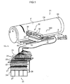
- Fig. 1 is a structural diagram of a plate making apparatus to which a multi-beam exposure scanning apparatus is applied, according to an embodiment of the presently disclosed subject matter.
- a sheet-shaped plate member F (corresponding to a "recording medium") is fixed to an outer circumferential surface of a drum 50 having a cylindrical shape.
- the drum 50 is rotated in an arrow R direction (a main-scanning direction) in Fig. 1 .
- a plurality of laser beams according to image data of an image to be engraved (recorded) on the plate member F are emitted from an exposure head 30 of a laser recording apparatus 10 toward the plate member F.
- a two-dimensional image can be engraved (recorded) on the surface of the plate member F at high speed.
- engraving on a rubber plate or a resin plate for flexography is described as an example.
- the laser recording apparatus 10 to be used for the plate making apparatus 11 includes a light source unit 20 generating a plurality of laser beams; an exposure head 30 irradiating the plate member F with the plurality of laser beams generated by the light source unit 20; and an exposure head moving unit 40 moving the exposure head 30 along the sub-scanning direction.
- the light source unit 20 includes a plurality of (here, 32 in total) semiconductor lasers 21. Light from each of the semiconductor lasers 21 is individually transmitted via optical fibers 22 and 70 to an optical fiber array unit 300 of the exposure head 30.
- broad-area semiconductor lasers (wavelength: 915 mm) are used as the semiconductor lasers 21.
- the semiconductor lasers 21 are arranged in a line on a light source substrate 24.
- the semiconductor lasers 21 are individually coupled to one ends of the optical fibers 22, and the other ends of the optical fibers 22 are each connected to an adaptor of an FC-type optical connector (Fiber transmission system optical Connector) 25.
- FC-type optical connector Fiber transmission system optical Connector
- An adaptor substrate 23 supports the FC-type optical connector 25 and is mounted vertically on one end of the light source substrate 24.
- an LD (Laser Diode) driver substrate 27 equipped with LD driver circuits (not illustrated in Fig. 1 and denoted as a reference numeral 26 in Fig. 7 ) driving the semiconductor lasers 21 are mounted on the other end of the light source substrate 24.
- Each of the semiconductor lasers 21 is connected to a corresponding one of the LD driver circuits via an individual wiring member 29. With this, each of the semiconductor lasers 21 is individually driven and controlled.
- multi-mode optical fibers having a relatively large core diameter are applied to the optical fibers 70 in order to obtain high output of laser beams.
- optical fibers having a core diameter of 105 ⁇ m are used.
- the semiconductor lasers 21 for use have a maximum output on the order of 10 W.
- those having a core diameter of 105 ⁇ m and an output of 10 W distributed from JDS Uniphase Corporation (6398-L4) can be adopted.
- the optical fiber array unit 300 gathering and emitting laser beams emitted from the plurality of semiconductor lasers 21 is provided on the exposure head 30.
- a light emitting unit (not illustrated in Fig. 1 and denoted as a reference numeral 280 in Fig. 2 ) of the optical fiber array unit 300 is configured in a manner such that emission ends of 32 optical fibers 70 led from the semiconductor lasers 21 are arranged in a line (refer to Fig. 3 ).
- a collimator lens 32, an opening member 33, and an imaging lens 34 are arranged in a line in sequence from a light emitting unit side of the optical fiber array unit 300.
- the combination of the collimator lens 32 and the imaging lens 34 configures an imaging optical system.
- the opening member 33 is arranged at a position so that the opening is a far field position when viewed from an optical fiber array unit 300 side. With this, a light amount limiting effect can be equally given to all laser beams emitted from the optical fiber array unit 300.
- the exposure head moving unit 40 includes a ball screw 41 and two rails 42 arranged in a manner such that a longitudinal direction thereof is along the sub-scanning direction.
- a sub-scanning motor (not illustrated in Fig. 1 and denoted as a reference numeral 43 in Fig. 7 ) and driving the ball screw 41 by rotation, the exposure head 30 arranged on the ball screw 41 can be moved in the sub-scanning direction as being guided by the rails 42.
- the drum 50 can be driven by rotation in an arrow R direction in Fig. 1 by activating a main-scanning motor (not illustrated in Fig. 1 and denoted as a reference numeral 51 in Fig. 7 ). With this, a main scan is performed.
- Fig. 2 is a structural diagram of the optical fiber array unit 300
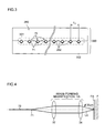
- Fig. 3 is an enlarged view (a view from an arrow A in Fig. 2 ) of the light emitting unit 280.
- optical fibers 70 having a cladding diameter of 125 ⁇ m and a core diameter of 105 ⁇ m and equidistantly emitting 32 light beams are arranged in a straight line.
- the optical fiber array unit 300 has a base (a V-groove substrate) 302, and V-shaped grooves 282 as many as the number of the semiconductor lasers 21, that is, 32 V-shaped grooves 282, are formed in the base 302 so as to be adjacent to each other with a predetermined space.
- the other end of each of the optical fiber 70 that is, an optical fiber end 71, fit in.
- an optical fiber end group 301 with the optical fiber ends is arranged in a straight line. Therefore, from the optical emitting unit 280 of the optical fiber array unit 300, these plurality of (32) laser beams are simultaneously emitted.
- Fig. 4 is an overview diagram of an image-forming optical system of the optical fiber array unit 300.
- imaging means including the collimator lens 32 and the imaging lens 34 an image is formed from the laser beams emitted from the light emitting unit 280 of the optical fiber array unit 300 near an exposure surface (a front surface) FA of the plate member F at a predetermined image-forming magnification.
- the image-forming magnification is assumed to 1/3.
- a laser beam LA emitted from the optical fiber end 71 having a core diameter of 105 ⁇ m has a spot diameter of ⁇ 35 ⁇ m.
- an interval P1 between scanning lines (main scanning lines) K subjected to exposure with laser beams emitted from optical fibers arranged at adjacent positions can be set at 10.58 ⁇ m (corresponding to a resolution of 2400 dpi in the sub-scanning direction).
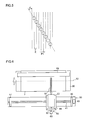
- Fig. 6 is a plan view illustrating an overview of a scanning exposure system of in the plate making apparatus 11 illustrated in Fig. 1 .
- the exposure head 30 includes a focus position changing mechanism 60 and a mechanism 90 for intermittently feeding in the sub-scanning direction.
- the focus position changing mechanism 60 includes a motor 61 and a ball screw 62 for moving the exposure head 30 forward and backward with respect to a surface of the drum 50. With the control by the motor 61, a focus position can be moved by approximately 339 ⁇ m in approximately 0.1 seconds.
- the intermittent feeding mechanism 90 forms the exposure head moving unit 40 described with reference to Fig. 1 and, as illustrated in Fig. 6 , includes a ball screw 41 and a sub-scanning motor 43 for rotating the ball screw 41.
- reference numerals 46 and 47 denote bearings rotatably supporting the ball screw 41.
- a reference numeral 55 denotes a chuck member chucking the plate member F on the drum 50. The position of this chuck member 55 is in a non-recording area where exposure (recording) by the exposure head 30 is not performed. While the drum 50 is being rotated, the plate member F on this rotating drum 50 is irradiated with laser beams of 32 channels from the exposure head 30, an exposure range 92 of 32 channels (one swath) is exposed without a gap, thereby performing engraving (image recording) with one swath width on the surface of the plate member F.
- sheet-shaped plate member F (recording medium) is used in the present example, a cylindrical recording medium (a sleeve type) can be used.
- Fig. 7 is a block diagram illustrating the structure of a control system in the plate making apparatus 11.
- the plate making apparatus 11 includes the LD driver circuits 26 driving each of the semiconductor lasers 21 according to two-dimensional image data to be engraved, a main-scanning motor 51 rotating the drum 50, a main-scanning motor driving circuit 81 driving the main-scanning motor 51, a sub-scanning motor driving circuit 82 driving the sub-scanning motor 43, and a control circuit 80.
- the control circuit 80 controls the LD driver circuits 26 and each of the motor driving circuits (81 and 82).
- control circuit 80 image data representing an image to be engraved (recorded) on the plate member F. Based on this image data, the control circuit 80 controls the driving of the main-scanning motor 51 and the sub-scanning motor 43, and also individually controls an output of each of the semiconductor lasers 21 (ON/OFF control and laser beam power control).
- a peripheral part (a surrounding part) of a flat shape (a print surface) 200 to be left on the surface of the plate member F is taken as a precise engraving area (a first area) 202, and a further peripheral part (outside) thereof is taken as a rough engraving are (a second area) 204.
- a main scan exposure scanning
- the precise engraving area 202 is subjected to interlaced exposure by using beams with a space therebetween twice as large as the interval between the scanning lines, and the rough engraving area 204 is subjected to simultaneous exposure by using all beams.
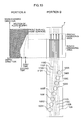
- Fig. 9 to Fig. 12 are diagrams illustrating first to fourth exposure scanning at the same sub-scanning position.
- Portion A in each of Fig. 9 to Fig. 12 illustrates a section of the plate member F after engraving.
- Portion B in each of Fig. 9 to Fig. 12 illustrates exposure control of laser beams 100A to 100H emitted from optical fiber ends 71A to 71H to scanning lines 110A to 110H, respectively.
- the number of laser beams is decreased in the drawings, and an example is illustrated in which the plate member F is subjected to a main scan with the laser beams 100A to 100H relatively in an upper direction in each drawing.
- the section of the plate member F illustrated in Portion A of each of Fig. 9 to Fig. 12 has a different degree of engraving depth depending on which scanning line among the laser beams 100A to 100D the section is on.
- an average engraving dept of the section on each scanning line is illustrated.
- non-interlaced exposure is performed on the rough engraving area by using all of the laser beams 100A to 100H to engrave each of the scanning lines 110A to 110H.
- exposure is performed with a plurality of beams arranged in a diagonal direction, with heat of the beam at the previous scanning, the depth ratio of engraving with the beam for the next scanning is increased. Therefore, by performing engraving in this manner, an inflow of heat of adjacent beams is promoted, thereby improving engraving efficiency.
- control is performed so that outputs of the laser beams 100A to 100H are linearly decreased as coming closer to the precise engraving area, thereby preventing unwanted engraving due to an inflow of heat into the precise engraving area.
- interlaced exposure is performed by using a beam group with an interval between adjacent beams twice as large as the interval between the scanning lines, thereby engraving a scanning line in every other line.
- a beam group with an interval between adjacent beams twice as large as the interval between the scanning lines, thereby engraving a scanning line in every other line.
- Outputs of the laser beams 100B, 100D, 100F, and 100H emitted to the precise engraving area are preferably higher than those emitted to the rough engraving area. That is, when exposure is simultaneously performed with only a plurality of beams arranged in the sub-scanning direction, by increasing laser beam power by an amount of engraving efficiency improved by simultaneously performing exposure with a plurality of beams arranged in a diagonal direction, the engraving depth and engraving width for one main scan can be both made similar, and therefore continuity between the precise engraving area and the rough engraving area can be kept.
- outputs of the laser beams 100B, 100D, 100F, and 100H are controlled to be linearly decreased as coming closer to the print surface. With this control, the influence of heat occurring due to the previously-passing adjacent beams can be mitigated, and therefore unwanted engraving due to an inflow of heat into the print surface can be prevented.
- non-interlaced exposure is performed by using all of the laser beams 100A to 100H to promote an inflow of heat of the adjacent beams to improve engraving efficiency, thereby engraving the scanning lines 110A to 110H. Also, as with the first main scan, control is performed so that outputs of the laser beams 100A to 100H are linearly decreased as coming closer to the precise engraving area.
- interlaced exposure is performed by using a beam group with an interval between adjacent beams twice as large as the interval between the scanning lines and not used at the first time, thereby engraving scanning lines not engraved at the first time. That is, as illustrated in Portion B of Fig. 10 , among the laser beams 100A to 100H emitted from the optical fiber ends 71A to 71H, the laser beams 100A, 100C, 100E, and 100G (a second beam group) are used for exposure scanning, thereby engraving the scanning lines 110A, 110C, 110E, and 110G.
- outputs of the laser beams 100A, 100C, 100E, and 100G emitted to the precise engraving area are preferably higher than outputs emitted to the rough engraving area.
- the engraving depth and engraving width for one main scan can be both made similar, and therefore continuity between the precise engraving area and the rough engraving area can be kept.
- an output of the laser beam 100D is controlled to be linearly decreased as coming closer to the print surface. With this control, unwanted engraving due to an inflow of heat into the print surface can be prevented.
- the surface of the plate member F is subjected to engraving as illustrated in Portion A of Fig. 10 . That is, the rough engraving area is subjected to engraving deeper than the section at the first time, with the engraving depth becoming shallower as coming closer to the precise engraving area.
- the scanning lines 110B, 110D, 110F, and 110H engraved at the first time and the scanning lines 110A, 110C, 110E, and 110G engraved at the second time are present in the precise engraving area. That is, with these two exposures, all of the scanning lines are uniformly engraved at the sub-scanning positions. Also, as with the rough engraving area, the engraving depth becomes shallower as coming closer to the print surface.
- non-interlaced exposure is performed by using the laser beams 100A to 100H, thereby engraving the scanning lines 110A to 110H.
- interlaced exposure (superposed exposure) is performed by using a beam group with an interval between adjacent beams twice as large as the interval between the scanning lines, thereby engraving a scanning line in every other line.
- exposure scanning is performed by using the same first beam group as used in the first exposure scanning, thereby engraving the scanning lines 110B, 110D, 110F, and 110H.
- the surface of the plate member F is subjected to engraving as illustrated in Portion A of Fig. 11 . That is, the rough engraving area is subjected to engraving further deeper than the section at the second time, and the scanning lines 110B, 110D, 110F, and 110H obtained by scanning with the first beam group are deeply engraved in the precise engraving area.
- non-interlaced exposure for a fourth time is performed with the laser beams 100A to 100H, thereby engraving the scanning lines 110A to 110H.
- interlaced exposure (superposed exposure) is performed by using a beam group with an interval between adjacent beams twice as large as the interval between the scanning lines and not used at the third time, thereby engraving scanning lines not engraved at the third time.
- by using only the same second beam group as used in the second main scan thereby engraving the scanning lines 110A, 110C, 110E, and 110G.
- the surface of the plate member F is subjected to engraving as illustrated in Portion A of Fig. 12 . That is, the rough engraving area is subjected to engraving further deeper than the section at the third time, with the engraving depth becoming shallower as coming closer to the precise engraving area. Also, in the precise engraving area, all of the scanning lines at the sub-scanning positions are uniformly engraved with the third and fourth main scans. Furthermore, in the precise engraving area, engraving is performed so that an steep edge portion with respect to the print surface is eventually formed.
- the beam group with an interval between adjacent beams twice as large as the interval between the scanning lines is used in the peripheral part (the precise engraving area) of the surface shape to be eventually left as a projected flat part.
- scanning lines to be exposed with a plurality of times of scanning being varied, unexposed scanning lines between exposed scanning lines are sequentially exposed.
- N is an integer equal to 2 or more
- Nxm times is an integer equal to 2 or more
- Nxm times is an integer equal to 2 or more
- any desired numbers can be combined as appropriate as long as they are each equal to 2 or more.
- the sequence of interlaced exposure may not be the same as the sequence of exposure scanning illustrated in Fig. 9 to Fig. 12 .
- exposure in the first main scan may be performed by the first beam group (Portion A of Fig. 13 )
- exposure in the second main scan may be next performed by the second beam group (Portion B of Fig. 13 )
- exposure in the third main scan may be then performed again by the second beam group (Portion C of Fig. 13 )
- exposure in the fourth main scan may be performed by the first beam group (Portion D of Fig. 13 ).
- interlaced exposure is not necessarily restricted to alternate exposure.
- the sequence may be such that the first beam group and the second beam group are exchanged with each other.
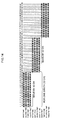
- Fig. 14 is a diagram schematically illustrating this state.
- each square represents each of the optical fiber ends 71 of the exposure head 30.
- hatched portions each represent that a laser beam output is performed in the rough engraving area.
- Black circle portions each represent that a laser beam output is performed in the precise engraving area.
- all beam groups are used for exposure in the rough engraving area, and a beam group with an interval between adjacent beams twice as large as the interval between the scanning lines is used for exposure in the precise engraving area.
- all beam groups are used for exposure in the rough engraving area, and a beam group with an interval between adjacent beams twice as large as the interval between the scanning lines and not used at the first time is used for exposure in the precise engraving area.
- all beam groups are used for exposure in the rough engraving area, and the same beam group with the interval between adjacent beams twice as large as the interval between the scanning lines and used at the first time is used for exposure in the precise engraving area.
- all beam groups are used for exposure in the rough engraving area, and the same beam group with the interval between adjacent beams twice as large as the interval between the scanning lines and used at the second time is used for exposure in the precise engraving area.
- the exposure head 30 is moved by 32 ch in the sub-scanning direction (in a right direction in Fig. 14 ). Then, at this position, four exposures are performed for exposure for 32 ch.
- each scanning line is exposed with the same beam.
- a sub-scanning feed by 32 ch corresponding to a total number beams of the exposure head 30 is performed. That is, a sub-scanning feed is performed by an amount equal to the product of the total number of beams and the scanning line width.
- the sub-scanning feed is not meant to be restricted to the example illustrated in Fig. 14 .
- a residual unengraved portion between swathes may occur.
- an area with redundant beam groups may be provided for a sub-scanning feed.
- Fig. 15 is a diagram illustrating the case of a sub-scanning feed by 29 ch after four scans. As illustrated in the drawing, a beam group for 3 ch from left is not used in first to fourth exposures. Other than that, the control is similar to that in exposure illustrated in Fig. 14 .
- the exposure head 30 is moved by 29 ch in the sub-scanning direction (in a right direction in Fig. 15 ).
- all beam groups are used in the rough engraving area. That is, 30th, 31st, and 32nd lines from left of the plate member F are exposed with beams for 3 ch from right of the head 30 in the first to fourth main scans, and are further exposed with beams for 3 ch from left of the head 30 in fifth to eighth main scans. With this exposure, a residual unengraved portion between swathes can be suppressed.
- the beam group with an interval between adjacent beams twice as large as the interval between the scanning lines is used for exposure in the precise engraving area
- the beam group for 3 ch from left may be exposed as required at the time of the fifth to eighth main scans.
- each scanning line can be exposed with the same beam, and an area with redundant beam groups can also be provided for a sub-scanning feed. That is; a sub-scanning feed may be performed for an amount smaller than the product of the total number of beams and the scanning line width by a predetermined amount.
- Fig. 16 is a diagram schematically illustrating a sub-scanning feed by 8 ch for every main scan.
- a start line of an image to be exposed is set at a 25th line.
- a beam groups for 24 ch from left is not used.
- the all remaining beam groups are used for exposure in the rough engraving area, and a beam group with an interval between adjacent beams twice as large as the interval between the scanning lines is used for exposure in the precise engraving area.
- a sub-scanning feed for 8 ch (the interval between the scanning lines ⁇ 8) is performed for a second exposure.
- a beam group for 16 ch from left is not used.
- the all remaining beam groups are used for exposure in the rough engraving area, and a beam group with an interval between adjacent beams twice as large as the interval between the scanning lines and different from that for the first time is used for exposure in the precise engraving area.
- a sub-scanning feed for 8 ch is performed for a third exposure.
- a beam group for 8 ch from left is not used.
- the all remaining beam groups are used for exposure in the rough engraving area, and a beam group with an interval between adjacent beams twice as large as the interval between the scanning lines and the same as that for the first time is used for exposure in the precise engraving area.
- a sub-scanning feed for 8 ch is performed for a fourth exposure.
- all beam groups are used for exposure in the rough engraving area, and a beam group with an interval between adjacent beams twice as large as the interval between the scanning lines and the same as that for the second time is used for exposure in the precise engraving area.
- a sub-scanning feed for 8 ch is performed for a fifth exposure.
- all beam groups are used for exposure in the rough engraving area, and a beam group with an interval between adjacent beams twice as large as the interval between the scanning lines and the same as that for the first time is used for exposure in the precise engraving area.
- sub-scanning may be equidistantly performed for every main scan. While a sub-scanning feed is performed for 8 ch is performed herein, the number of sub-scanning feed is any as long as it is a submultiple of the number of beams (32 ch). That is, a sub-scanning can be performed for an amount equal to a submultiple of the number of beams and the scanning line width.
- a spiral exposure scheme may be adopted in which the exposure head 30 is moved at a predetermined speed in the sub-scanning direction during the rotation of the drum 50 for scanning the surface of the plate member F in a spiral shape.
- the intermittent feed scheme is effective when the rotation speed of the drum is relatively slow.
- the spiral exposure scheme is effective when the rotation speed of the drum is relatively quick.
- a sub-scanning feed is equidistantly performed for every main scan in the example illustrated in Fig. 16
- a sub-scanning feed may be non-equidistantly performed for every main scan.
- Fig. 17 is a diagram schematically illustrating a sub-scanning feed for 7 ch or 9 ch for every scan.
- a beam group for 23 ch from left is not used. Then, the all remaining beam groups are used for exposure in the rough engraving area, and a beam group with an interval between adjacent beams twice as large as the interval between the scanning lines is used for exposure in the precise engraving area.
- a sub-scanning feed for 7 ch is performed in a second exposure.
- a beam group for 16 ch from left is not used.
- the all remaining beam groups are used for exposure in the rough engraving area.
- a sub-scanning feed for 9 ch is performed in a third exposure.
- a beam group for 7 ch from left is not used.
- the all remaining beam groups are used for exposure in the rough engraving area.
- a sub-scanning feed for 7 ch is performed in a fourth exposure.
- all beam groups are used for exposure in the rough engraving area.
- a beam group with an interval between adjacent beams twice as large as the interval between the scanning lines and the same as that at the third time is used for exposure.
- a sub-scanning feed for 9 ch is performed in a fifth exposure. Also in the fifth exposure, all beam groups are used for exposure in the rough engraving area, and a beam group with an interval between adjacent beams twice as large as the interval between the scanning lines and the same as ever is used for exposure in the precise engraving area.
- one main scan and sub-scans for 7 ch or 9 ch are repeated.
- a residual unengraved portion between swathes can be reduced. Note that while the head from which 32 laser beams are simultaneously emitted has been described herein as an example, the number of beams and the amount of sub-scanning feed can be determined as appropriate.
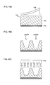
- FIGs. 18A, 18B, and 18C illustrate an overview of a plate making method.
- a raw plate 700 for use in plate making by laser engraving has an engraving layer 704 (a rubber layer or a resin layer) on a substrate 702, and a protective cover film 706 is affixed onto the engraving layer 704.
- the engraving layer 704 is exposed to the outside by peeling off the cover film 706, and the engraving layer 704 is irradiated with laser light, thereby removing unit of the engraving layer 704 and forming a desired three-dimensional shape (refer to Fig. 18B ).
- a specific laser engraving method is as described with reference to Fig. 1 to Fig. 17 . Note that dust occurring during laser engraving is suctioned by a suctioning apparatus not illustrated for collection.
- a cleaning apparatus 710 water cleaning by a cleaning apparatus 710 is performed (a cleaning process). Then, after a drying process (not illustrated), a flexographic plate is complete.
- a plate making scheme of direct laser engraving on the plate itself is called a direct engraving scheme.
- the plate making apparatus to which the multi-beam exposure scanning apparatus according to the present embodiment is applied can be achieved at lower cost, compared with a laser engraving machine using CO 2 laser. Also, by making beams into multi-beam, an improvement in processing speed can be achieved, thereby improving productivity of printing plates.
- the presently disclosed subject matter can be applied not only to manufacture of a flexographic plate but also to manufacture of another relief printing plate or an intaglio printing plate. Furthermore, the presently disclosed subject matter can be applied not only to manufacture of a printing plate but also to a rendering recording apparatus and engraving apparatus for other various purposes.
- a multi-beam exposure scanning method in which a plurality of beams are simultaneously emitted with a predetermined interval between scanning lines toward a recording medium for exposure scanning a plurality of times with a same scanning line, thereby performing engraving on a surface of the recording medium, wherein interlaced exposure using a beam group with an interval between adjacent beams N times (N is an integer equal to 2 or more) larger than the interval between the scanning lines is repeatedly performed Nxm times (m is an integer equal to 2 or more) on a first area, which is an area surrounding a flat-shaped target area to be left on the surface of the recording medium to be exposed, to expose each of the scanning lines m times, and non-interlaced exposure using a beam group with an interval between adjacent beams equal to the interval between the scanning lines is performed on a second area, which is outside the first area.
- the non-interlaced exposure is repeatedly performed Nxm times on the second area.
- a shape of a tilted part surrounding the flat-shaped target area is engraved by decreasing outputs of beams as coming closer to the flat-shaped target area to be left on the surface of the recording medium to be exposed.
- the shape of the tilted part around the target flat shape can be engraved.
- a multi-beam exposure scanning apparatus including an exposure head simultaneously emitting a plurality of beams toward a recording medium to perform engraving on a surface of the recording medium, main-scanning means relatively moving the recording medium and the exposure head in a main-scanning direction for exposure scanning a plurality of times with a same scanning line, and exposure scanning control means controlling the exposure head and the main-scanning means so that interlaced exposure using a beam group with an interval between adjacent beams N times (N is an integer equal to 2 or more) larger than the interval between the scanning lines is repeatedly performed Nxm times (m is an integer equal to 2 or more) on a first area, which is an area surrounding a flat-shaped target area to be left on the surface of the recording medium to be exposed, to expose each of the scanning lines m times, and non-interlaced exposure using a beam group with an interval between adjacent beams equal to the interval between the scanning lines is performed on a second area, which is outside the first area.
- the non-interlaced exposure is repeatedly performed Nxm times on the second area.
- the multi-beam exposure scanning apparatus further includes sub-scanning means causing the exposure head to perform sub-scanning the recording medium relatively in a sub-scanning direction orthogonal to the main-scanning direction, wherein the sub-scanning means causes the sub-scanning intermittently by a predetermined amount with respect to main-scanning by the main-scanning means.
- the sub-scanning means causes the sub-scanning by a predetermined amount for every Nxm main scans by the main-scanning means.
- the predetermined mount is equal to a product of a number of beams that can be emitted from the exposure head and the interval between the scanning lines.
- the predetermined amount is smaller than a product of a number of beams that can be emitted from the exposure head and the interval between the scanning lines.
- the sub-scanning means causes the sub-scanning by a predetermined amount for every main scan by the main-scanning means.
- the predetermined amount is equal to a submultiple of a product of a number of beams that can be emitted from the exposure head and the interval between the scanning lines.
- the predetermined amount has a plurality of values.
- the main-scanning means has a drum rotating as holding the recording medium by an outer circumferential surface
- the apparatus further includes sub-scanning means moving the exposure head along an axial direction of the drum, wherein spiral exposure scanning is performed with a sub-scanning feed parallel to an axial direction of the drum being taken as a continuous feed.
- a printing plate manufacturing method wherein, with the multi-beam exposure scanning method according to any one of the first to third aspects of the presently disclosed subject matter, a printing plate is obtained by performing engraving on a surface of a plate member corresponding to the recording medium.
Landscapes
- Physics & Mathematics (AREA)
- General Physics & Mathematics (AREA)
- Optics & Photonics (AREA)
- Exposure And Positioning Against Photoresist Photosensitive Materials (AREA)
- Manufacture Or Reproduction Of Printing Formes (AREA)
- Laser Beam Processing (AREA)
- Exposure Of Semiconductors, Excluding Electron Or Ion Beam Exposure (AREA)
- Printers Or Recording Devices Using Electromagnetic And Radiation Means (AREA)
Applications Claiming Priority (1)
| Application Number | Priority Date | Filing Date | Title |
|---|---|---|---|
| JP2011185121A JP5318166B2 (ja) | 2011-08-26 | 2011-08-26 | マルチビーム露光走査方法及び装置並びに印刷版の製造方法 |
Publications (2)
| Publication Number | Publication Date |
|---|---|
| EP2562600A2 true EP2562600A2 (de) | 2013-02-27 |
| EP2562600A3 EP2562600A3 (de) | 2013-11-13 |
Family
ID=47088650
Family Applications (1)
| Application Number | Title | Priority Date | Filing Date |
|---|---|---|---|
| EP12181526.0A Withdrawn EP2562600A3 (de) | 2011-08-26 | 2012-08-23 | Verfahren und Vorrichtung für Abtastung mit Mehrstrahlbelichtung und Verfahren zur Herstellung einer Druckplatte |
Country Status (3)
| Country | Link |
|---|---|
| US (1) | US20130048843A1 (de) |
| EP (1) | EP2562600A3 (de) |
| JP (1) | JP5318166B2 (de) |
Families Citing this family (5)
| Publication number | Priority date | Publication date | Assignee | Title |
|---|---|---|---|---|
| JP3215568B2 (ja) | 1994-02-08 | 2001-10-09 | 株式会社小松製作所 | 鋳鋼品の表面硬化材および表面硬化方法 |
| JP6230416B2 (ja) * | 2013-12-27 | 2017-11-15 | 株式会社Screenホールディングス | 記録装置および記録ヘッド制御方法 |
| KR101526078B1 (ko) * | 2013-12-27 | 2015-06-04 | 아주하이텍(주) | Ldi 노광장치 및 그 장치를 이용한 노광방법 |
| US10307867B2 (en) | 2014-11-05 | 2019-06-04 | Asm Technology Singapore Pte Ltd | Laser fiber array for singulating semiconductor wafers |
| JP2022187985A (ja) * | 2021-06-08 | 2022-12-20 | 株式会社リコー | 容器及び収容体、並びに容器の製造方法及び容器の製造装置 |
Citations (1)
| Publication number | Priority date | Publication date | Assignee | Title |
|---|---|---|---|---|
| JP2010134292A (ja) | 2008-12-05 | 2010-06-17 | Fujifilm Corp | マルチビーム露光走査方法及び装置並びに印刷版の製造方法 |
Family Cites Families (9)
| Publication number | Priority date | Publication date | Assignee | Title |
|---|---|---|---|---|
| JPH04138253A (ja) * | 1990-09-28 | 1992-05-12 | Dainippon Screen Mfg Co Ltd | グラビアセル彫刻方法及びその装置 |
| JP2803999B2 (ja) * | 1993-11-10 | 1998-09-24 | 現代電子産業株式会社 | 半導体装置の微細パターン製造法 |
| JPH0985927A (ja) * | 1995-09-25 | 1997-03-31 | Dainippon Screen Mfg Co Ltd | グラビア印刷版製造装置およびグラビア印刷版製造方法 |
| JP3552197B2 (ja) * | 1998-11-06 | 2004-08-11 | 大日本スクリーン製造株式会社 | 画像記録装置 |
| JP2001277464A (ja) * | 2000-03-29 | 2001-10-09 | Think Laboratory Co Ltd | 製版用レーザ露光装置 |
| ATE282527T1 (de) * | 2001-05-25 | 2004-12-15 | Stork Prints Austria Gmbh | Verfahren und vorrichtund zur herstellung einer druckform |
| JP2008203506A (ja) * | 2007-02-20 | 2008-09-04 | Shinko Electric Ind Co Ltd | マスクレス露光方法及び装置 |
| JP2009172658A (ja) * | 2008-01-25 | 2009-08-06 | Fujifilm Corp | 露光装置 |
| JP5078163B2 (ja) * | 2008-12-05 | 2012-11-21 | 富士フイルム株式会社 | マルチビーム露光走査方法及び装置並びに印刷版の製造方法 |
-
2011
- 2011-08-26 JP JP2011185121A patent/JP5318166B2/ja not_active Expired - Fee Related
-
2012
- 2012-08-23 EP EP12181526.0A patent/EP2562600A3/de not_active Withdrawn
- 2012-08-24 US US13/594,508 patent/US20130048843A1/en not_active Abandoned
Patent Citations (1)
| Publication number | Priority date | Publication date | Assignee | Title |
|---|---|---|---|---|
| JP2010134292A (ja) | 2008-12-05 | 2010-06-17 | Fujifilm Corp | マルチビーム露光走査方法及び装置並びに印刷版の製造方法 |
Also Published As
| Publication number | Publication date |
|---|---|
| JP5318166B2 (ja) | 2013-10-16 |
| JP2013043440A (ja) | 2013-03-04 |
| US20130048843A1 (en) | 2013-02-28 |
| EP2562600A3 (de) | 2013-11-13 |
Similar Documents
| Publication | Publication Date | Title |
|---|---|---|
| JP5220794B2 (ja) | マルチビーム露光走査方法及び装置並びに印刷版の製造方法 | |
| US20110261137A1 (en) | Multi-beam exposure scanning method and apparatus, and method for manufacturing printing plate | |
| EP2562600A2 (de) | Verfahren und Vorrichtung für Abtastung mit Mehrstrahlbelichtung und Verfahren zur Herstellung einer Druckplatte | |
| EP2475523B1 (de) | Bildgebungskopf für 3d-abbildung | |
| US8418612B2 (en) | Printing plate making apparatus and printing plate making method | |
| JP2009172658A (ja) | 露光装置 | |
| JP2009214334A (ja) | 製版装置及び製版方法 | |
| HK1052320A1 (en) | Method and device for producing a printing block | |
| CN102239450B (zh) | 多光束曝光扫描方法和设备,以及用于制造印刷版的方法 | |
| CN1754694A (zh) | 印刷版的制版方法以及印刷版的制版装置 | |
| JP5389797B2 (ja) | 位置合わせ可能な印刷スリーブセグメント | |
| JP2010237298A (ja) | 彫刻モニタリング方法及び装置、製版装置、並びに印刷版の製造方法 | |
| JP5213272B2 (ja) | マルチビーム露光走査方法及び装置並びに印刷版の製造方法 | |
| US8969757B2 (en) | Relief manufacturing apparatus and relief manufacturing method | |
| JP5578909B2 (ja) | 露光走査装置 | |
| JP5220793B2 (ja) | マルチビーム露光走査方法及び装置並びに印刷版の製造方法 | |
| JP2009172922A (ja) | 製版装置 | |
| US20120320352A1 (en) | Multibeam exposure scanning method and apparatus, and method of manufacturing printing plate | |
| JP2009199040A (ja) | 露光装置 |
Legal Events
| Date | Code | Title | Description |
|---|---|---|---|
| PUAI | Public reference made under article 153(3) epc to a published international application that has entered the european phase |
Free format text: ORIGINAL CODE: 0009012 |
|
| AK | Designated contracting states |
Kind code of ref document: A2 Designated state(s): AL AT BE BG CH CY CZ DE DK EE ES FI FR GB GR HR HU IE IS IT LI LT LU LV MC MK MT NL NO PL PT RO RS SE SI SK SM TR |
|
| AX | Request for extension of the european patent |
Extension state: BA ME |
|
| PUAL | Search report despatched |
Free format text: ORIGINAL CODE: 0009013 |
|
| AK | Designated contracting states |
Kind code of ref document: A3 Designated state(s): AL AT BE BG CH CY CZ DE DK EE ES FI FR GB GR HR HU IE IS IT LI LT LU LV MC MK MT NL NO PL PT RO RS SE SI SK SM TR |
|
| AX | Request for extension of the european patent |
Extension state: BA ME |
|
| RIC1 | Information provided on ipc code assigned before grant |
Ipc: G03F 7/24 20060101ALI20131009BHEP Ipc: B41C 1/05 20060101ALI20131009BHEP Ipc: G03F 7/20 20060101AFI20131009BHEP |
|
| 17P | Request for examination filed |
Effective date: 20140509 |
|
| RBV | Designated contracting states (corrected) |
Designated state(s): AL AT BE BG CH CY CZ DE DK EE ES FI FR GB GR HR HU IE IS IT LI LT LU LV MC MK MT NL NO PL PT RO RS SE SI SK SM TR |
|
| STAA | Information on the status of an ep patent application or granted ep patent |
Free format text: STATUS: THE APPLICATION IS DEEMED TO BE WITHDRAWN |
|
| 18D | Application deemed to be withdrawn |
Effective date: 20170301 |