EP2559834B1 - Dispositif de fermeture pour portes de véhicules - Google Patents
Dispositif de fermeture pour portes de véhicules Download PDFInfo
- Publication number
- EP2559834B1 EP2559834B1 EP12180698.8A EP12180698A EP2559834B1 EP 2559834 B1 EP2559834 B1 EP 2559834B1 EP 12180698 A EP12180698 A EP 12180698A EP 2559834 B1 EP2559834 B1 EP 2559834B1
- Authority
- EP
- European Patent Office
- Prior art keywords
- locking tongue
- door
- opening
- trigger
- bolt
- Prior art date
- Legal status (The legal status is an assumption and is not a legal conclusion. Google has not performed a legal analysis and makes no representation as to the accuracy of the status listed.)
- Active
Links
- 230000000903 blocking effect Effects 0.000 claims description 13
- 238000003780 insertion Methods 0.000 claims description 11
- 230000037431 insertion Effects 0.000 claims description 11
- 230000003137 locomotive effect Effects 0.000 description 7
- 230000007935 neutral effect Effects 0.000 description 7
- 238000000034 method Methods 0.000 description 6
- 230000007257 malfunction Effects 0.000 description 3
- 238000007789 sealing Methods 0.000 description 3
- 241001295925 Gegenes Species 0.000 description 2
- 238000005192 partition Methods 0.000 description 2
- 230000002093 peripheral effect Effects 0.000 description 2
- 240000006829 Ficus sundaica Species 0.000 description 1
- 230000005540 biological transmission Effects 0.000 description 1
- 230000001419 dependent effect Effects 0.000 description 1
- 238000010586 diagram Methods 0.000 description 1
- 230000002996 emotional effect Effects 0.000 description 1
- 230000003068 static effect Effects 0.000 description 1
Images


Classifications
-
- E—FIXED CONSTRUCTIONS
- E05—LOCKS; KEYS; WINDOW OR DOOR FITTINGS; SAFES
- E05B—LOCKS; ACCESSORIES THEREFOR; HANDCUFFS
- E05B17/00—Accessories in connection with locks
- E05B17/0025—Devices for forcing the wing firmly against its seat or to initiate the opening of the wing
-
- E—FIXED CONSTRUCTIONS
- E05—LOCKS; KEYS; WINDOW OR DOOR FITTINGS; SAFES
- E05B—LOCKS; ACCESSORIES THEREFOR; HANDCUFFS
- E05B59/00—Locks with latches separate from the lock-bolts or with a plurality of latches or lock-bolts
-
- E—FIXED CONSTRUCTIONS
- E05—LOCKS; KEYS; WINDOW OR DOOR FITTINGS; SAFES
- E05B—LOCKS; ACCESSORIES THEREFOR; HANDCUFFS
- E05B63/00—Locks or fastenings with special structural characteristics
- E05B63/18—Locks or fastenings with special structural characteristics with arrangements independent of the locking mechanism for retaining the bolt or latch in the retracted position
- E05B63/185—Preventing actuation of a bolt when the wing is open
-
- E—FIXED CONSTRUCTIONS
- E05—LOCKS; KEYS; WINDOW OR DOOR FITTINGS; SAFES
- E05B—LOCKS; ACCESSORIES THEREFOR; HANDCUFFS
- E05B83/00—Vehicle locks specially adapted for particular types of wing or vehicle
- E05B83/36—Locks for passenger or like doors
- E05B83/363—Locks for passenger or like doors for railway vehicles
-
- E—FIXED CONSTRUCTIONS
- E05—LOCKS; KEYS; WINDOW OR DOOR FITTINGS; SAFES
- E05B—LOCKS; ACCESSORIES THEREFOR; HANDCUFFS
- E05B15/00—Other details of locks; Parts for engagement by bolts of fastening devices
- E05B15/0053—Other details of locks; Parts for engagement by bolts of fastening devices means providing a stable, i.e. indexed, position of lock parts
-
- E—FIXED CONSTRUCTIONS
- E05—LOCKS; KEYS; WINDOW OR DOOR FITTINGS; SAFES
- E05B—LOCKS; ACCESSORIES THEREFOR; HANDCUFFS
- E05B65/00—Locks or fastenings for special use
- E05B65/001—Locks or fastenings for special use for gas- or watertight wings
Definitions
- the present invention relates to a locking device for vehicle doors, in particular for pressure-tight doors in the interior of rail vehicles, and to a rail vehicle having a door with such a locking device.
- a locomotive driver's cab is separated from the engine room by a partition. A door is built into this partition, which must perform certain functions to ensure the safe operation of a locomotive. First and foremost, an escape route from the driver's cab must be ensured if there is a risk of collision. Secondly, the engine driver should be given the opportunity to be able to lock the driver's cab in a pressure-tight manner in order to avoid pressure equalization when driving through tunnels and during train encounters.
- the door is equipped with a locking system consisting of a mortise lock, a lever on the driver's cab side and a door handle on the machine room side.
- a locking system consisting of a mortise lock, a lever on the driver's cab side and a door handle on the machine room side.
- components such as a striking plate in the door frame, synonymous with the term "door frame”, and all around sealing seals, in particular hollow chamber seals, are installed on the door leaf and / or the door frame.
- the lever extends, for example in the form of a bar, across the door leaf and is articulated at both ends.
- a pressing device hereinafter also referred to as "ratchet"
- the grater engages with a bolt in an opening in the striking plate which has an oblique edge and is also referred to as a "grater trap”.
- the door leaf is pressed against the door frame, wherein the door leaf is pressed against peripheral seals on the door frame, or peripheral seals attached to the door leaf are pressed against the door frame.
- the latch should basically only be able to be actuated for the purpose of pressure-tight locking if the locking tongue engages or has engaged in the lock latch. An earlier actuation of the grater can cause the lock to malfunction. The all-round seals can cause the door to spring back during the closing process. In this situation, if the locking tongue has not yet engaged in the lock latch, but the lock-in can already be actuated and its bolt is extended, it may happen that the lock of the lock-in does not engage in the lock-in latch as intended and instead the bolt against the Presses the door frame or a striking plate attached there, or the door is pulled to the side of the door frame with the extended grater.
- Known locking devices have a locking device for the latch, which is intended to prevent actuation of the latch before the locking tongue engages in the lock latch.
- the known solutions are unsatisfactory since they are not free from malfunctions and the locking tongue and the grater can still act independently of one another.
- DE 10 2010 005 261 A1 started from the problem of making a rail vehicle door lock known from the non-documented prior art more flexible, in such a way that the lock has fewer functional restrictions.
- the solution of DE 10 2010 005 261 A1 is characterized in that the latch has a holding surface which can be contacted by blocking with a counter-holding surface of the blocking device.
- the solution of DE 10 2010 005 261 A1 consists essentially in having the blocking device no longer act on an auxiliary pawl but directly on the lock pawl, the lock pawl now being able to be locked not only in the blocking position, but also being able to assume different positions even when the blocking device is activated.
- EP 0 668 425 A1 discloses a door lock with a latch which can be actuated via a nut part and with a bolt which is operatively connected to the nut part in such a way that it can be retracted together with the latch.
- the bolt is retractable against the force of a biasing spring via a gear which has a locking mechanism.
- the locking mechanism engages the bolt or a gear member in such a way that the bolt can be locked in any retracted position at least in one end section of its retraction movement.
- the locking mechanism can be released via a position sensor protruding from the door lock, the bolt being extendable under the action of the biasing spring.
- EP 1 031 686 A2 discloses a lock with a trigger-operated and lockable main latch that snaps into a striker, and with an auxiliary latch that is inserted through the striker when the door is closed and that locks the main latch when inserted.
- the main latch acts on a locking device which engages the auxiliary latch and holds it in its extended position, such as a locking lever which engages with a control edge on a surface directed against the direction of insertion, in particular on a stop of the auxiliary latch.
- the inlet surface of the main latch head being in front of the inlet surface of the auxiliary latch head for the advance release of the auxiliary latch lock in the course of the closing process of the door.
- auxiliary latch pushed in automatically by spring force and retractable by a handle and / or locking cylinder.
- a tumbler holding the spring-loaded bolt in the retracted position assigned to the bolt which can be swiveled into the release position of the tumbler or rocker when the auxiliary latch is inserted.
- a bolt or slide is slidably mounted in or on the shaft of the auxiliary trap, which in the inserted position of the auxiliary trap has on the one hand a from the main latch when projecting the same actuable release lever and on the other hand with the tumbler, in particular rocker for kinematically aligning so that it is released only when the main latch protrudes into a latch pocket of the striker, the bolt is released for rushing into its latch pocket of the striker.
- An object of the invention was to provide an improved locking device in which the grater can only be actuated when the locking tongue engages in the lock latch.
- the closing tongue moves into the first opening (also referred to as a lock latch) when the door is closed, thus engages in the first opening.
- the locking tongue and the trigger move relative to one another.
- the closed state of the door engagement of the locking tongue in the lock latch
- the locking tongue and the trigger assume a position which is changed relative to one another in comparison to the opened state of the door.
- the locking tongue projects completely or partially from the locking device, in particular from a housing of the locking device.
- the locking device is in particular attached to a door leaf and the locking tongue protrudes over an edge of the door leaf.
- the locking tongue is first moved into the locking device (or into a housing of the locking device) and then, when the door is closed, it is moved out of the locking device again, e.g. by a spring, and engages in the first opening arranged on the door frame.
- the term "opening” means an opening with a depth extension so that a bolt or a locking tongue can engage. Instead of the term “opening”, the terms “recess” or “recess” can also be used.
- the locking tongue can assume the same position within the locking device when the door is closed as when the door is open. In the closed state of the door, the closing tongue can also assume a different position within the closing device compared to the opened state of the door.
- the trigger When the door is closed, the trigger is preferably moved such that it assumes a different position within the closing device when the door is closed than when the door is open.
- the trigger is moved into the closing device when the door is closed, for example by pressing the door frame, a striking plate or another component provided on the door frame against the trigger.
- both parts become relative to one another emotional.
- the locking tongue occupies a different position within the locking device than when the door is open, and the trigger also takes a different position within the locking device when the door is closed than when the door is open, then the positions are from Trigger and locking tongue matched to each other so that both parts are moved relative to each other.
- the relative movement of the locking tongue and the trigger is used to transfer the pressure device (also referred to as a grater) from the locked state to the unlocked state.
- the relative movement can only take place, and the unlocking device can only be unlocked when the locking tongue engages in the lock latch.
- the two components locking tongue and trigger are functionally dependent on each other.
- the trigger can only move relative to the locking tongue when the locking tongue engages in the lock latch. This ensures that the function of the trigger is linked to the function of the lock tongue.
- the term “trigger” means that this element, in cooperation with the locking tongue, “triggers” the unlocked state of the pressing device directly or indirectly.
- the trigger serves to bring the pressing device, in cooperation with the locking tongue, directly or indirectly (for example via a mechanism that is still present) from the locked to the unlocked state.
- the trigger in cooperation with the locking tongue, causes the pressing device to be held in the locked state as long as the locking tongue does not engage in the first opening and that the pressing device is brought into the unlocked state when the locking tongue engages in the first opening.
- the trigger is in particular a sliding element. When the door is open, the trigger can protrude with a part of its body out of the locking device and protrude from a door leaf to which the locking device is attached. When the door is closed, all or part of the protruding part of the trigger can be pressed into the locking device.
- a bolt of the pressing device is inserted into a second opening in the door frame (also referred to as a rub-in trap) with an obliquely running edge, so that the door leaf can be moved along the oblique edge is pressed against the door frame.
- the term "inclined edge” means in particular that the edge is not perpendicular.
- the sloping edge can have a straight, non-vertical course or a curved course.
- the edge runs obliquely in the direction of the closing direction of the door leaf, so that when the bolt moves along the edge, the door leaf is pressed against the door frame.
- door frame is synonymous with the term "door frame”.
- the pressing device is preferably rotatable and the bolt is moved into the friction trap by a rotary movement.
- the second opening tapers downward and the bolt of the pressing device is turned into the grater trap from above. He grinds down along the sloping edge and presses the door leaf against the frame.
- the opening with the inclined edge can, for example, have a contour tapering downwards or upwards, in particular a wedge-shaped contour.
- the door frame has a surface against which the door leaf bears when the door is closed, or an edge against which the door leaf bears when the door is closed.
- the door can have a seal, with which an intermediate space between the door leaf and frame can be sealed when the door is closed, preferably a circumferential seal for pressure-tight sealing.
- An example is a hollow chamber seal.
- the seal can be attached to the frame and / or on the door leaf.
- the seal can be attached to the surface on which the door leaf rests when the door is closed, or on the edge against which the door leaf rests when the door is closed.
- the closing tongue and the trigger are preferably coupled to one another.
- the trigger and the locking tongue are connected to a mechanism, also referred to as a "trigger mechanism", which is moved by the relative movement of the trigger and the locking tongue, and which transfers the pressing device from the locked state to the unlocked state.
- the mechanism is preferably movable relative to the trigger and closing tongue, preferably rotatable and / or displaceable.
- the mechanism is a locking / unlocking device which is movably coupled to the locking tongue and to the trigger, preferably articulated, so that the locking / unlocking device is caused by the relative movement of the locking tongue and trigger acts on the pressing device and transfers the pressing device from the locked state to the unlocked state.
- said unlocking device is a lever which is articulated on the locking tongue and the trigger, so that the lever can be deflected by a relative movement of the locking tongue and the trigger and can act on said locking device.
- the locking device is in particular a pawl.
- the pawl can be pivoted to a housing of the locking device.
- a return spring can be provided which moves the pawl into the first position.
- the locking device In the first position, the locking device preferably engages the pressing device and prevents movement of the pressing device and insertion of the bolt of the pressing device into the second opening. In other words, the locking device blocks the pressing device in the first position.
- the locking device In the second position, the locking device preferably does not engage in the pressing device, so that movement of the pressing device and insertion of the bolt of the pressing device into the second opening are made possible.
- the trigger is movable parallel to the locking tongue, and at the time when the locking tongue engages in the first opening arranged on the door frame, the trigger is not movable by the same distance as the locking tongue, so that when the locking tongue engages in the first opening, a Relative movement between Trigger and locking tongue can be generated.
- the trigger can have the form of a bolt and can be arranged parallel and adjacent to the locking tongue.
- a special mechanism works as follows: When a door is open, the locking tongue and the trigger protrude from the locking device and protrude from the door leaf, preferably by the same distance.
- the locking tongue and the trigger are first moved into the locking device so that the door leaf can be moved past the edge of the door frame.
- the locking tongue reaches the lock latch, it engages in the lock latch and moves out of the locking device and the door leaf again. Then the door is closed. No opening is provided for the trigger, into which it can engage, so that it cannot be moved out of the closing device and the door leaf by the same distance as the closing tongue.
- the locking tongue and the trigger move relative to one another in comparison with the open state of the door.
- the door operating lever is preferably movable in a second position, wherein when the door operating lever is moved into the second position, the latch of the pressing device is moved out of the second opening arranged in the door frame, and the closing tongue and the pressing device are designed such that when the door operating lever moves in the second position the pressing device acts on the locking tongue and moves the locking tongue out of the first opening.
- An example of such a configuration of the locking tongue and the pressing device is given in the exemplary embodiments.
- the door operating lever is preferably located on the cab side.
- the vehicle driver can lock the door pressure-tight by moving the lever into the first position and release the pressing device again by moving into the second position and move the locking tongue out of the first opening so that the door can be opened.
- Movement to the second position is preferably done by pressing by hand and the door leaf is opened by pressing so that it can be opened quickly from the driver's cab in an emergency.
- the locking device has a striking plate for attachment to a door frame, the striking plate having the first opening and the second opening.
- the invention relates to rail vehicles which have a door, as described above, in particular a pressure-tight door.
- These rail vehicles are especially locomotives and power cars.
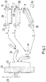
- the Figure 1a shows a locking device 7 and a striking plate 8 in the closed state of a door.
- the locking device 7 is attached to a door leaf (not shown) and the striking plate 8 is attached to a door frame (not shown).
- the striking plate 8 is shown in two views.
- the left representation of the striking plate 8 shows a top view of the striking plate from a slightly oblique perspective. You can see a first opening A, which is also referred to as a lock latch, and a second opening B, also referred to as a rub-in latch. Furthermore, two elongated holes 9 can be seen, which can accommodate screws (not shown) with which the striking plate 8 can be fastened to a door frame.
- the right part of the Figure 1a shows the striking plate 8 in cross section, wherein the first opening A is cut and the second opening B is not cut.
- the locking device 7 has a housing 10.
- the Figure 1b shows the locking device 7 in the open state of a door.
- the locking tongue 1 protrudes laterally from the housing 10 and is held in this position by the return spring 13.
- a trigger 4 is arranged above the locking tongue 1 and protrudes the same distance from the housing 10 and is held in the position shown by a return spring 12.
- a lever 5 is movably connected to the locking tongue 1 and the trigger 4. The lever 5 is articulated on the locking tongue 1 via the pin 16 and the lever 5 can be rotated relative to the locking tongue 1 about the axis specified by the pin 16. Via the pin 17, the lever 5 is at one end on the trigger 4 articulated and rotatable relative to the trigger 4 about the axis predetermined by the pin 17.
- the pin 17 engages in an elongated hole of the lever 5 so that the lever 5 in the Figure 1a shown deflection can perform.
- the lever 5 rests against the end 20 of a pawl 3 which is pivotably articulated on the housing 10 with the pin 21.
- the pawl 3 With a second end 22, which tapers to a point, the pawl 3 is in contact with a pressing device (rubber) 2 and blocks the rubber 2 in the Figure 1b shown position: the linager 2 is in the locked state.
- the grater 2 is rotatable per se about the axis 23 perpendicular to the plane of the drawing, with a rotary movement of the grater 2 in the state shown here Figure 1b is prevented by the adjacent pawl 3.
- the pawl 3 is connected to a return spring (not shown) which the pawl 3 in the in Figure 1b shown position is when no force through the lever 5 counteracts this.
- the pawl 3 is shown in its first position, in which it holds the latch 2 in the locked state, that is to say blocks the latch 2, so that the insertion of the bolt 11 of the latch 2 into the second opening B of the striking plate 8 is prevented.
- the Indian Figure 1b The shown state of the grater 2 is the locked state, since the grater 2 cannot be rotated about the axis 23 and the bolt 11 cannot be moved out of the housing 10 and rotated into the grater trap B by rotating the grater 2 clockwise.
- either one side M is pressed, which in the preferred use of the door is the engine room side of a locomotive, or a second side F, which is the driver's side of a locomotive in the preferred use of the door.
- the side of the engine room is pressed against the door leaf Figure 2 shown with the arrow labeled M and pulling in the direction of the cab is in the Figure 2 represented by the arrow labeled F.
- Use force to close the door as that in the Figure 2 Hollow chamber seals 27 shown cause the door leaf 26 to spring back and this restoring force must be overcome.
- the locking tongue 1 is first moved into the housing 10.
- the pawl 29 on the machine room side can be actuated, or the locking tongue 1 is pressed against an edge of the door frame (reference symbol 30 in Figure 3 ) and / or pressed against an edge 28 of the striking plate 8.
- the locking tongue can also be pressed back into the housing 10 without actuating the pawl against the force of the springs 13.
- the closed state of the door is both in the Fig. 1a as well in the Fig. 2 shown.
- the locking tongue 1 falls, moves by the spring 13 into the latch A and holds the door in the closed state.
- the trigger 4 is actuated due to the shape of the striking plate 8.
- the striking plate 8 has no opening into which the trigger 4 could engage, which is why the trigger is prevented from rushing out of the housing 10 and bears against the surface of the striking plate 8.
- the trigger 4 and the locking tongue 1 move relative to one another when the locking tongue 1 engages in the opening A.
- the trigger 4 and the closing tongue 1 are moved against each other.
- the relative movement of the trigger 4 and the locking tongue 1 causes the lever 5 to be deflected, as in FIG Fig. 1a shown.
- the end 18 of the lever 5 presses against the end 20 of the pawl 3, whereby the pawl, articulated with the pin 21, from its first position ( Fig. 1b ) in a second position ( Fig. 1a ) is deflected.
- the pawl 3 releases the grater 2.
- the pusher is brought into the unlocked state and can be turned counterclockwise about the axis 23, and the latch 11 of the pusher can engage in the second opening (B) in the striking plate 8, as in FIG Fig. 1a and 2 shown.
- the fact that the triggering of the trigger 4, the deflection of the lever 5 and the deflection of the pawl can only take place when the locking tongue 1 has snapped into the latch B, the time of release for the grater 2 is fixed.
- the grater is rotated by operating the lever 31, as in the Figure 3 still explained.
- the bolt 11 is screwed into the opening B and moved along the inclined edge 33 of the opening B until it arrives in the lower region of the opening B (see. Fig. 2 and 1a ).
- the bolt 11 rubs along the inclined edge 33 and the door leaf 26 is moved in the direction of the arrow M or F ( Fig. 2 ) pulled and against the door frame 30 (s. Fig. 3 ) pressed.
- seals 27 are attached to the door leaf 26, which are compressed when the door leaf 26 is pressed against the frame 30 and close the door in a pressure-tight manner.
- the door leaf 26 can be mounted on the door frame 30 all-round seals are pressed and the door is locked pressure-tight.
- the second opening B tapers downward and the bolt 11 of the pressing device is turned into the friction trap from above.
- the edge 33 runs obliquely downwards in the direction of the closing direction of the door leaf, the closing direction being indicated by the arrows M and F ( Fig. 2 ) is shown.
- the Figure 1a shows the closed state of the door (locking tongue engages in opening A) and the pressure-tight locking of the door, since the latch 11 of the grater engages in opening B and is deflected to the maximum.
- the return bar 14 is pressed by the springs 15 against a second flat side 34 of the grater 2, whereby the grater is held in the position shown.
- Fig. 1c the unlocking process of the door is shown.
- the operating lever 31 is in a second position (explained in the following using the Fig. 3 ) you can unlock and open the door again.
- the grater 2 is rotated clockwise about the axis 23.
- the reset bar 14, articulated with the pin 25 on the housing 10 is pushed back somewhat by the grater 2 against the force of the springs 15.
- the bolt 11, which also rotates clockwise, strikes a projection 35 on the locking tongue 1 and presses the locking tongue 1 against the force of the spring 13 back into the housing.
- the lever 5 is rotated counterclockwise about the axis 16 into a vertical position.
- the tongue 1 contains a stop inside (not shown), via which the trigger 4 is also pressed into the housing.
- the lever 5 has reached the starting position and cannot turn any further because it is fixed to the trigger by a bolt 17.
- the locking tongue 1 is pressed further into the housing and takes the trigger 4 together with the lever 5 over the stop and presses it against the force of the spring 12 into the housing.
- the Fig. 3 shows the function of the door operating lever 31.
- the door operating lever 31 has a bracket shape and a locomotive is articulated on the driver's side at two ends on the door leaf 26.
- the Figure 2 shows the door operating lever 31.
- On the other A pawl 29 is attached to the door leaf 26 on the side of the door leaf.
- the door operating lever 31 is connected to the pressing device 2 (see FIG. 1a-1c ) coupled by actuating the door operating lever 31 about the axis 23 (s. 1a-1c ) can be turned clockwise and counterclockwise.
- the linear movement of the door operating lever 31 (when pulling and pushing) is implemented via a bevel gear transmission (not shown) in the housing 40 of the door operating lever 31.
- the door operating lever 31 (hereinafter abbreviated as lever 31) can be brought into three different positions: the first position X, the second position Y and the third position Z, which can also be referred to as the neutral position.
- the lever 31 can be pulled from the driver's compartment when the door is open, whereby the door leaf closes and the locking tongue 1 first strikes the frame 30, then is pressed into the locking device and finally into the lock latch (first Opening A) occurs.
- resistance of the resilient hollow chamber seals 27 Fig. 2
- the closed state of the door is reached when the locking tongue 1 engages in the lock latch and in the middle illustration on the right in the Fig. 3 shown.
- the door can also be closed by touching the pawl 29 and pressing against the door leaf 26 from the machine room side. By actuating the pawl 29, the locking tongue 1 can be drawn in.
- the door is locked in a pressure-tight manner by pulling the lever 31 upward from the neutral position Z shown in dashed lines to the first position X, as indicated by the obliquely upward arrow.
- the lever 31 By moving the lever 31 into the position X, the bolt 11 is inserted into the second opening B with a sloping edge 33 by a rotary movement of the grater 2 and the door leaf 26 is pressed against the door frame 30, the seals 27 sealing the door in a pressure-tight manner.
- the position of the grater 2 and the lever 11, which is caused by setting the lever 31 in the position X, is in the Fig. 1a and in the Fig. 3 shown at the top right.
- the lever 31 To unlock and open the door on the driver's side, the lever 31 is moved from the first position X to the second position Y, the lever 31 being pressed downwards in the direction of the door leaf 26.
- the neutral position Z is passed through during this movement.
- the lever 31 When the lever 31 is moved from the first position X to the neutral position Z, the latch 11 of the grater 2 is released from the action of the lever 31 Rub-in trap B unscrewed.
- the locking tongue 1 In the neutral position, the locking tongue 1 is not yet pushed back by the bolt 11, as in the Fig. 1c shown. Only when the lever 31 is pressed further in the direction of the door leaf 26 and the second position Y is reached are the locking tongue 1 and the trigger 4 pushed back and the locking tongue is moved out of the first opening, as in FIG Fig. 1c shown, in the position Y of the lever 31, the door can be opened, as in the Fig. 3 pictured below right.
- the door can be opened by moving the lever 31.
- the driver only has to press the lever 31 and bring it into the Y position, the door being simultaneously opened by the pushing movement. Operation is facilitated by the lever shape of the lever and can be carried out quickly, which should ensure that the driver quickly escapes from the driver's compartment in emergencies. Therefore, the lever 31 in the bracket shape shown is also referred to as a "panic bar”.
- the lever 31 is preferably provided with a return spring (not shown) which returns the lever 31 from the second position Y to the neutral position Z after the door has been opened.
Claims (9)
- Dispositif de fermeture (7) pour des portes de véhicule, en particulier pour des portes étanches à la pression à l'intérieur de véhicules ferroviaires, présentant- une languette de fermeture (1), qui peut être introduite dans une première ouverture (A) disposée au niveau d'un cadre de porte (30),- un déclencheur (4), qui est mobile, lors de l'introduction de la languette de fermeture (1) dans la première ouverture (A), par rapport à la languette de fermeture (1) et qui sert à faire passer le système de compression (2) de l'état bloqué à l'état débloqué en coopération avec la languette de fermeture (1),
dans lequel
du fait du déplacement relatif du déclencheur (4) et de la languette de fermeture (1) lors de l'introduction de la languette de fermeture dans la première ouverture (A), le système de compression (2) peut passer de l'état bloqué à l'état débloqué et le verrou (11) du système de compression peut être introduit dans la seconde ouverture (B),
caractérisé par- un système de compression (2), qui peut adopter un état débloqué et un état bloqué, dans lequel dans l'état débloqué, un verrou (11) du système de compression (2) peut être introduit dans une seconde ouverture (B) disposée dans le cadre de porte (30) avec un bord s'étendant de manière oblique de sorte qu'un vantail de porte (26) est pressé du fait du déplacement du verrou le long du bord s'étendant de manière oblique contre le cadre de porte et dans l'état bloqué, le verrou (11) ne peut pas être introduit dans la seconde ouverture (B), et- un levier d'actionnement de porte (31), qui est couplé au système de compression (2) et qui peut être déplacé dans une première position, dans lequel lors du déplacement du levier d'actionnement de porte (31) dans la première position, le verrou (11) du système de compression (2) est introduit dans la seconde ouverture (B) avec un bord s'étendant de manière oblique et le vantail de porte (26) est pressé contre le cadre de porte (30) du fait du déplacement du verrou le long du bord s'étendant de manière oblique. - Dispositif de fermeture selon la revendication 1, où le déclencheur (4) et la languette de fermeture (1) sont reliés à un mécanisme, lequel est déplacé du fait du déplacement relatif du déclencheur (4) et de la languette de fermeture (1) et lequel fait passer le système de compression (2) de l'état bloqué à l'état débloqué.
- Dispositif de fermeture selon l'une quelconque des revendications précédentes, présentant un système de blocage/déblocage (3, 5), qui est couplé de manière mobile à la languette de fermeture (1) et au déclencheur (4) si bien que du fait du déplacement relatif de la languette de fermeture (1) et du déclencheur (4), le système de blocage/déblocage (3, 5) agit sur le système de compression (2) et fait passer le système de compression (2) de l'état bloqué à l'état débloqué.
- Dispositif de fermeture selon la revendication 3, où le système de bocage/déblocage (3, 5) présente les éléments suivant :- un système de blocage (3), qui maintient dans une première position le système de compression (2) dans l'état bloqué si bien que l'introduction du verrou (11) du système de compression (2) dans la seconde ouverture (B) est empêchée, et libère, dans une seconde position, le système de compression (2) dans l'état débloqué si bien que l'introduction du verrou (11) dans la seconde ouverture (B) est rendue possible,- un système de déblocage (5), qui est couplé de manière mobile à la languette de fermeture (1) et au déclencheur (4) et peut être déplacé du fait du déplacement relatif de la languette de fermeture (1) et du déclencheur (4) lors de l'introduction de la languette de fermeture (1) dans la première ouverture (A), peut agir sur le système de blocage (3) et peut déplacer le système de blocage de la première position à la seconde position.
- Dispositif de fermeture selon la revendication 4, où le système de déblocage (5) est un levier, qui est articulé au niveau de la languette de fermeture (1) et du déclencheur (4) si bien que du fait d'un déplacement relatif de la languette de fermeture et du déclencheur, le levier peut être dévié et peut agir sur le système de blocage (3).
- Dispositif de fermeture selon l'une quelconque des revendications précédentes, où le déclencheur (4) est mobile parallèlement à la languette de fermeture (1), dans lequel au moment où la languette de fermeture (1) vient en prise avec la première ouverture (A) disposée au niveau du cadre de porte (30), le déclencheur (4) n'est pas mobile autour du même parcours que la languette de fermeture si bien que du fait de la prise de la languette de fermeture (1) avec la première ouverture (A), un déplacement relatif peut être généré entre le déclencheur et la languette de fermeture.
- Dispositif de fermeture selon la revendication 1, dans lequel le levier d'actionnement de porte (31) peut être déplacé dans une seconde position, dans lequel lors du déplacement du levier d'actionnement de porte (31) dans la seconde position, le verrou (11) du système de compression (2) est déplacé de manière à sortir de la seconde ouverture (B) disposée dans le cadre de porte (30), et la languette de fermeture (1) et le système de compression (2) sont configurés de telle sorte que lors du déplacement du levier d'actionnement de porte dans la seconde position, le système de compression (2) agit sur la languette de fermeture (1) et déplace la languette de fermeture de manière à sortir de la première ouverture (A) .
- Dispositif de fermeture selon l'une quelconque des revendications précédentes, présentant par ailleurs une tôle de fermeture (8) destinée à être installée au niveau d'un cadre de porte (30), qui présente la première ouverture (A) et la seconde ouverture (B).
- Véhicule ferroviaire, présentant une porte, en particulier une porte étanche à la pression, avec un dispositif de fermeture selon l'une quelconque des revendications 1 à 8.
Priority Applications (1)
| Application Number | Priority Date | Filing Date | Title |
|---|---|---|---|
| PL12180698T PL2559834T3 (pl) | 2011-08-18 | 2012-08-16 | Zamek do drzwi pojazdu |
Applications Claiming Priority (1)
| Application Number | Priority Date | Filing Date | Title |
|---|---|---|---|
| DE102011081189A DE102011081189A1 (de) | 2011-08-18 | 2011-08-18 | Schließvorrichtung für Fahrzeugtüren |
Publications (3)
| Publication Number | Publication Date |
|---|---|
| EP2559834A2 EP2559834A2 (fr) | 2013-02-20 |
| EP2559834A3 EP2559834A3 (fr) | 2017-08-23 |
| EP2559834B1 true EP2559834B1 (fr) | 2020-01-01 |
Family
ID=46934412
Family Applications (1)
| Application Number | Title | Priority Date | Filing Date |
|---|---|---|---|
| EP12180698.8A Active EP2559834B1 (fr) | 2011-08-18 | 2012-08-16 | Dispositif de fermeture pour portes de véhicules |
Country Status (4)
| Country | Link |
|---|---|
| EP (1) | EP2559834B1 (fr) |
| DE (1) | DE102011081189A1 (fr) |
| ES (1) | ES2780380T3 (fr) |
| PL (1) | PL2559834T3 (fr) |
Family Cites Families (11)
| Publication number | Priority date | Publication date | Assignee | Title |
|---|---|---|---|---|
| GB191311932A (en) * | 1913-05-22 | 1914-02-05 | William Ralston Carson | Improved Fastenings for Doors, Windows and the like. |
| FR572617A (fr) * | 1923-11-03 | 1924-06-10 | Serrure de glacière | |
| DE453492C (de) * | 1925-12-25 | 1927-12-07 | Brown Boveri & Cie Akt Ges Abt | Schloss fuer Tueren von Kuehlschraenken u. dgl. |
| GB519411A (en) * | 1939-05-05 | 1940-03-26 | Eugen Moessmer | Improvements in or relating to fastening means for doors, windows or the like |
| DE3908688C2 (de) * | 1989-03-16 | 1997-06-12 | Gruenzweig & Hartmann Montage | Einsteck- oder Kastenschloß für schalldämmende Türen |
| DE3937154A1 (de) * | 1989-11-08 | 1991-05-16 | Kapolnek Schall Und Schwingung | Tuerschloss |
| ATE164909T1 (de) * | 1994-02-21 | 1998-04-15 | Hellmueller & Zingg Ag | Türschloss |
| GB2297794B (en) * | 1995-02-10 | 1998-12-30 | Hoong Thye Eldon Lee | Closure mechanism for airtight doors |
| AT407549B (de) * | 1999-02-24 | 2001-04-25 | Kaba Gege Gmbh | Schloss mit drückerbetätigbarer und verriegelbarer hauptfalle |
| GB2386393A (en) * | 2002-03-15 | 2003-09-17 | Surelock Mcgill Ltd | Bolting mechanism |
| DE102010005261B4 (de) * | 2010-01-20 | 2012-02-09 | Carl Wilhelm Cleff Gmbh & Co Kg | Schloss für eine Schienenfahrzeugtür |
-
2011
- 2011-08-18 DE DE102011081189A patent/DE102011081189A1/de not_active Ceased
-
2012
- 2012-08-16 PL PL12180698T patent/PL2559834T3/pl unknown
- 2012-08-16 EP EP12180698.8A patent/EP2559834B1/fr active Active
- 2012-08-16 ES ES12180698T patent/ES2780380T3/es active Active
Non-Patent Citations (1)
| Title |
|---|
| None * |
Also Published As
| Publication number | Publication date |
|---|---|
| EP2559834A3 (fr) | 2017-08-23 |
| PL2559834T3 (pl) | 2020-06-29 |
| EP2559834A2 (fr) | 2013-02-20 |
| ES2780380T3 (es) | 2020-08-25 |
| DE102011081189A1 (de) | 2013-02-21 |
Similar Documents
| Publication | Publication Date | Title |
|---|---|---|
| EP1932989B1 (fr) | Système de fermeture pour portes, fenêtres ou analogues, en particulier crémone-serrure à fonction d'urgence et de verrouillage à plusieurs points | |
| EP1178171B1 (fr) | Dispositif de verrouillage pour porte de véhicule automobile | |
| EP2569498B1 (fr) | Dispositif à poignée, en particulier pour un véhicule | |
| EP2845972A2 (fr) | Serrure de véhicule automobile | |
| DE102009029023A1 (de) | Kraftfahrzeugschloss | |
| EP2157396B1 (fr) | Porte de véhicule pour véhicules blindés comportant un pêne de protection contre les mines | |
| EP0521262A1 (fr) | Serrure | |
| EP1408187B1 (fr) | Dispositif d'actionnement d'une serrure pour portes, volets, ou similaires, en particulier sur véhicules | |
| EP3245361A1 (fr) | Serrure | |
| EP2706174B1 (fr) | Serrure pour une porte | |
| DE202005000939U1 (de) | Verriegelungseinrichtung | |
| EP2339096B1 (fr) | Serrure à crémone dotée d'une fonction anti-panique et d'un verrouillage multiple | |
| DE102009050077A1 (de) | Fahrzeugschloss | |
| EP0634543A1 (fr) | Serrure à combinaison avec bouton tournant, disque à cames et un levier | |
| EP2754798B1 (fr) | Dispositif de serrure de porte pour une porte d'au moins un battant | |
| DE19808374B4 (de) | Vorrichtung zum Verriegeln einer Abdeckung nach Art einer Karosseriehaube eines Kraftfahrzeugs | |
| DE202007016091U1 (de) | Treibstangenschloss | |
| DE2839760A1 (de) | Verriegelungsvorrichtung, insbesondere fuer tueren oder fenster | |
| DE102015000606A1 (de) | Verriegelungsvorrichtung für einen schwenkbar gelagerten Flügel | |
| EP2559834B1 (fr) | Dispositif de fermeture pour portes de véhicules | |
| EP3628801B1 (fr) | Dispositif de fermeture pour une porte et procédé pour ouvrir une porte | |
| DE10339542B4 (de) | Kraftfahrzeugtürverschluss | |
| DE102010053179A1 (de) | Kraftfahrzeugtürverschluss | |
| DE102004036655A1 (de) | Vorrichtung zum automatischen Schließen einer Fahrzeugtür | |
| DE102019125947B4 (de) | Notbetätigungsvorrichtung zum manuellen öffnen einer fahrzeugtür |
Legal Events
| Date | Code | Title | Description |
|---|---|---|---|
| PUAI | Public reference made under article 153(3) epc to a published international application that has entered the european phase |
Free format text: ORIGINAL CODE: 0009012 |
|
| AK | Designated contracting states |
Kind code of ref document: A2 Designated state(s): AL AT BE BG CH CY CZ DE DK EE ES FI FR GB GR HR HU IE IS IT LI LT LU LV MC MK MT NL NO PL PT RO RS SE SI SK SM TR |
|
| AX | Request for extension of the european patent |
Extension state: BA ME |
|
| PUAL | Search report despatched |
Free format text: ORIGINAL CODE: 0009013 |
|
| AK | Designated contracting states |
Kind code of ref document: A3 Designated state(s): AL AT BE BG CH CY CZ DE DK EE ES FI FR GB GR HR HU IE IS IT LI LT LU LV MC MK MT NL NO PL PT RO RS SE SI SK SM TR |
|
| AX | Request for extension of the european patent |
Extension state: BA ME |
|
| RIC1 | Information provided on ipc code assigned before grant |
Ipc: E05B 65/18 00000000ALI20170718BHEP Ipc: E05B 63/18 20060101ALI20170718BHEP Ipc: E05B 59/00 20060101ALI20170718BHEP Ipc: E05B 15/00 20060101ALI20170718BHEP Ipc: E05B 65/10 20060101ALI20170718BHEP Ipc: E05B 17/00 20060101AFI20170718BHEP |
|
| STAA | Information on the status of an ep patent application or granted ep patent |
Free format text: STATUS: REQUEST FOR EXAMINATION WAS MADE |
|
| 17P | Request for examination filed |
Effective date: 20180222 |
|
| RBV | Designated contracting states (corrected) |
Designated state(s): AL AT BE BG CH CY CZ DE DK EE ES FI FR GB GR HR HU IE IS IT LI LT LU LV MC MK MT NL NO PL PT RO RS SE SI SK SM TR |
|
| RIC1 | Information provided on ipc code assigned before grant |
Ipc: E05B 83/36 20140101ALI20190626BHEP Ipc: E05B 63/18 20060101ALI20190626BHEP Ipc: E05B 59/00 20060101ALI20190626BHEP Ipc: E05B 17/00 20060101AFI20190626BHEP Ipc: E05B 15/00 20060101ALI20190626BHEP Ipc: E05B 65/10 20060101ALI20190626BHEP Ipc: E05B 65/00 20060101ALI20190626BHEP |
|
| GRAP | Despatch of communication of intention to grant a patent |
Free format text: ORIGINAL CODE: EPIDOSNIGR1 |
|
| STAA | Information on the status of an ep patent application or granted ep patent |
Free format text: STATUS: GRANT OF PATENT IS INTENDED |
|
| INTG | Intention to grant announced |
Effective date: 20190805 |
|
| GRAS | Grant fee paid |
Free format text: ORIGINAL CODE: EPIDOSNIGR3 |
|
| GRAA | (expected) grant |
Free format text: ORIGINAL CODE: 0009210 |
|
| STAA | Information on the status of an ep patent application or granted ep patent |
Free format text: STATUS: THE PATENT HAS BEEN GRANTED |
|
| RAP1 | Party data changed (applicant data changed or rights of an application transferred) |
Owner name: BOMBARDIER TRANSPORTATION GMBH |
|
| AK | Designated contracting states |
Kind code of ref document: B1 Designated state(s): AL AT BE BG CH CY CZ DE DK EE ES FI FR GB GR HR HU IE IS IT LI LT LU LV MC MK MT NL NO PL PT RO RS SE SI SK SM TR |
|
| REG | Reference to a national code |
Ref country code: GB Ref legal event code: FG4D Free format text: NOT ENGLISH |
|
| REG | Reference to a national code |
Ref country code: AT Ref legal event code: REF Ref document number: 1219951 Country of ref document: AT Kind code of ref document: T Effective date: 20200115 Ref country code: CH Ref legal event code: EP |
|
| REG | Reference to a national code |
Ref country code: DE Ref legal event code: R096 Ref document number: 502012015652 Country of ref document: DE |
|
| REG | Reference to a national code |
Ref country code: IE Ref legal event code: FG4D Free format text: LANGUAGE OF EP DOCUMENT: GERMAN |
|
| REG | Reference to a national code |
Ref country code: CH Ref legal event code: NV Representative=s name: PATENTANWALT DIPL.-ING. (UNI.) WOLFGANG HEISEL, CH |
|
| REG | Reference to a national code |
Ref country code: NL Ref legal event code: FP |
|
| REG | Reference to a national code |
Ref country code: SE Ref legal event code: TRGR |
|
| REG | Reference to a national code |
Ref country code: LT Ref legal event code: MG4D |
|
| PG25 | Lapsed in a contracting state [announced via postgrant information from national office to epo] |
Ref country code: RS Free format text: LAPSE BECAUSE OF FAILURE TO SUBMIT A TRANSLATION OF THE DESCRIPTION OR TO PAY THE FEE WITHIN THE PRESCRIBED TIME-LIMIT Effective date: 20200101 Ref country code: LT Free format text: LAPSE BECAUSE OF FAILURE TO SUBMIT A TRANSLATION OF THE DESCRIPTION OR TO PAY THE FEE WITHIN THE PRESCRIBED TIME-LIMIT Effective date: 20200101 Ref country code: PT Free format text: LAPSE BECAUSE OF FAILURE TO SUBMIT A TRANSLATION OF THE DESCRIPTION OR TO PAY THE FEE WITHIN THE PRESCRIBED TIME-LIMIT Effective date: 20200527 Ref country code: FI Free format text: LAPSE BECAUSE OF FAILURE TO SUBMIT A TRANSLATION OF THE DESCRIPTION OR TO PAY THE FEE WITHIN THE PRESCRIBED TIME-LIMIT Effective date: 20200101 Ref country code: NO Free format text: LAPSE BECAUSE OF FAILURE TO SUBMIT A TRANSLATION OF THE DESCRIPTION OR TO PAY THE FEE WITHIN THE PRESCRIBED TIME-LIMIT Effective date: 20200401 |
|
| REG | Reference to a national code |
Ref country code: ES Ref legal event code: FG2A Ref document number: 2780380 Country of ref document: ES Kind code of ref document: T3 Effective date: 20200825 |
|
| PG25 | Lapsed in a contracting state [announced via postgrant information from national office to epo] |
Ref country code: GR Free format text: LAPSE BECAUSE OF FAILURE TO SUBMIT A TRANSLATION OF THE DESCRIPTION OR TO PAY THE FEE WITHIN THE PRESCRIBED TIME-LIMIT Effective date: 20200402 Ref country code: HR Free format text: LAPSE BECAUSE OF FAILURE TO SUBMIT A TRANSLATION OF THE DESCRIPTION OR TO PAY THE FEE WITHIN THE PRESCRIBED TIME-LIMIT Effective date: 20200101 Ref country code: IS Free format text: LAPSE BECAUSE OF FAILURE TO SUBMIT A TRANSLATION OF THE DESCRIPTION OR TO PAY THE FEE WITHIN THE PRESCRIBED TIME-LIMIT Effective date: 20200501 Ref country code: LV Free format text: LAPSE BECAUSE OF FAILURE TO SUBMIT A TRANSLATION OF THE DESCRIPTION OR TO PAY THE FEE WITHIN THE PRESCRIBED TIME-LIMIT Effective date: 20200101 Ref country code: BG Free format text: LAPSE BECAUSE OF FAILURE TO SUBMIT A TRANSLATION OF THE DESCRIPTION OR TO PAY THE FEE WITHIN THE PRESCRIBED TIME-LIMIT Effective date: 20200401 |
|
| REG | Reference to a national code |
Ref country code: DE Ref legal event code: R097 Ref document number: 502012015652 Country of ref document: DE |
|
| PG25 | Lapsed in a contracting state [announced via postgrant information from national office to epo] |
Ref country code: RO Free format text: LAPSE BECAUSE OF FAILURE TO SUBMIT A TRANSLATION OF THE DESCRIPTION OR TO PAY THE FEE WITHIN THE PRESCRIBED TIME-LIMIT Effective date: 20200101 Ref country code: DK Free format text: LAPSE BECAUSE OF FAILURE TO SUBMIT A TRANSLATION OF THE DESCRIPTION OR TO PAY THE FEE WITHIN THE PRESCRIBED TIME-LIMIT Effective date: 20200101 Ref country code: SK Free format text: LAPSE BECAUSE OF FAILURE TO SUBMIT A TRANSLATION OF THE DESCRIPTION OR TO PAY THE FEE WITHIN THE PRESCRIBED TIME-LIMIT Effective date: 20200101 Ref country code: EE Free format text: LAPSE BECAUSE OF FAILURE TO SUBMIT A TRANSLATION OF THE DESCRIPTION OR TO PAY THE FEE WITHIN THE PRESCRIBED TIME-LIMIT Effective date: 20200101 Ref country code: SM Free format text: LAPSE BECAUSE OF FAILURE TO SUBMIT A TRANSLATION OF THE DESCRIPTION OR TO PAY THE FEE WITHIN THE PRESCRIBED TIME-LIMIT Effective date: 20200101 |
|
| PLBE | No opposition filed within time limit |
Free format text: ORIGINAL CODE: 0009261 |
|
| STAA | Information on the status of an ep patent application or granted ep patent |
Free format text: STATUS: NO OPPOSITION FILED WITHIN TIME LIMIT |
|
| 26N | No opposition filed |
Effective date: 20201002 |
|
| PG25 | Lapsed in a contracting state [announced via postgrant information from national office to epo] |
Ref country code: SI Free format text: LAPSE BECAUSE OF FAILURE TO SUBMIT A TRANSLATION OF THE DESCRIPTION OR TO PAY THE FEE WITHIN THE PRESCRIBED TIME-LIMIT Effective date: 20200101 |
|
| PG25 | Lapsed in a contracting state [announced via postgrant information from national office to epo] |
Ref country code: MC Free format text: LAPSE BECAUSE OF FAILURE TO SUBMIT A TRANSLATION OF THE DESCRIPTION OR TO PAY THE FEE WITHIN THE PRESCRIBED TIME-LIMIT Effective date: 20200101 |
|
| GBPC | Gb: european patent ceased through non-payment of renewal fee |
Effective date: 20200816 |
|
| PG25 | Lapsed in a contracting state [announced via postgrant information from national office to epo] |
Ref country code: LU Free format text: LAPSE BECAUSE OF NON-PAYMENT OF DUE FEES Effective date: 20200816 |
|
| REG | Reference to a national code |
Ref country code: BE Ref legal event code: MM Effective date: 20200831 |
|
| PG25 | Lapsed in a contracting state [announced via postgrant information from national office to epo] |
Ref country code: BE Free format text: LAPSE BECAUSE OF NON-PAYMENT OF DUE FEES Effective date: 20200831 Ref country code: GB Free format text: LAPSE BECAUSE OF NON-PAYMENT OF DUE FEES Effective date: 20200816 Ref country code: IE Free format text: LAPSE BECAUSE OF NON-PAYMENT OF DUE FEES Effective date: 20200816 |
|
| PG25 | Lapsed in a contracting state [announced via postgrant information from national office to epo] |
Ref country code: TR Free format text: LAPSE BECAUSE OF FAILURE TO SUBMIT A TRANSLATION OF THE DESCRIPTION OR TO PAY THE FEE WITHIN THE PRESCRIBED TIME-LIMIT Effective date: 20200101 Ref country code: MT Free format text: LAPSE BECAUSE OF FAILURE TO SUBMIT A TRANSLATION OF THE DESCRIPTION OR TO PAY THE FEE WITHIN THE PRESCRIBED TIME-LIMIT Effective date: 20200101 Ref country code: CY Free format text: LAPSE BECAUSE OF FAILURE TO SUBMIT A TRANSLATION OF THE DESCRIPTION OR TO PAY THE FEE WITHIN THE PRESCRIBED TIME-LIMIT Effective date: 20200101 |
|
| PG25 | Lapsed in a contracting state [announced via postgrant information from national office to epo] |
Ref country code: MK Free format text: LAPSE BECAUSE OF FAILURE TO SUBMIT A TRANSLATION OF THE DESCRIPTION OR TO PAY THE FEE WITHIN THE PRESCRIBED TIME-LIMIT Effective date: 20200101 Ref country code: AL Free format text: LAPSE BECAUSE OF FAILURE TO SUBMIT A TRANSLATION OF THE DESCRIPTION OR TO PAY THE FEE WITHIN THE PRESCRIBED TIME-LIMIT Effective date: 20200101 |
|
| P01 | Opt-out of the competence of the unified patent court (upc) registered |
Effective date: 20230822 |
|
| PGFP | Annual fee paid to national office [announced via postgrant information from national office to epo] |
Ref country code: NL Payment date: 20230821 Year of fee payment: 12 |
|
| PGFP | Annual fee paid to national office [announced via postgrant information from national office to epo] |
Ref country code: IT Payment date: 20230825 Year of fee payment: 12 Ref country code: CZ Payment date: 20230807 Year of fee payment: 12 Ref country code: CH Payment date: 20230902 Year of fee payment: 12 Ref country code: AT Payment date: 20230822 Year of fee payment: 12 |
|
| PGFP | Annual fee paid to national office [announced via postgrant information from national office to epo] |
Ref country code: SE Payment date: 20230821 Year of fee payment: 12 Ref country code: PL Payment date: 20230811 Year of fee payment: 12 Ref country code: FR Payment date: 20230824 Year of fee payment: 12 Ref country code: DE Payment date: 20230821 Year of fee payment: 12 |
|
| PGFP | Annual fee paid to national office [announced via postgrant information from national office to epo] |
Ref country code: ES Payment date: 20231027 Year of fee payment: 12 |