EP2559834B1 - Closing device for vehicle doors - Google Patents
Closing device for vehicle doors Download PDFInfo
- Publication number
- EP2559834B1 EP2559834B1 EP12180698.8A EP12180698A EP2559834B1 EP 2559834 B1 EP2559834 B1 EP 2559834B1 EP 12180698 A EP12180698 A EP 12180698A EP 2559834 B1 EP2559834 B1 EP 2559834B1
- Authority
- EP
- European Patent Office
- Prior art keywords
- locking tongue
- door
- opening
- trigger
- bolt
- Prior art date
- Legal status (The legal status is an assumption and is not a legal conclusion. Google has not performed a legal analysis and makes no representation as to the accuracy of the status listed.)
- Active
Links
- 230000000903 blocking effect Effects 0.000 claims description 13
- 238000003780 insertion Methods 0.000 claims description 11
- 230000037431 insertion Effects 0.000 claims description 11
- 230000003137 locomotive effect Effects 0.000 description 7
- 230000007935 neutral effect Effects 0.000 description 7
- 238000000034 method Methods 0.000 description 6
- 230000007257 malfunction Effects 0.000 description 3
- 238000007789 sealing Methods 0.000 description 3
- 241001295925 Gegenes Species 0.000 description 2
- 238000005192 partition Methods 0.000 description 2
- 230000002093 peripheral effect Effects 0.000 description 2
- 240000006829 Ficus sundaica Species 0.000 description 1
- 230000005540 biological transmission Effects 0.000 description 1
- 230000001419 dependent effect Effects 0.000 description 1
- 238000010586 diagram Methods 0.000 description 1
- 230000002996 emotional effect Effects 0.000 description 1
- 230000003068 static effect Effects 0.000 description 1
Images


Classifications
-
- E—FIXED CONSTRUCTIONS
- E05—LOCKS; KEYS; WINDOW OR DOOR FITTINGS; SAFES
- E05B—LOCKS; ACCESSORIES THEREFOR; HANDCUFFS
- E05B17/00—Accessories in connection with locks
- E05B17/0025—Devices for forcing the wing firmly against its seat or to initiate the opening of the wing
-
- E—FIXED CONSTRUCTIONS
- E05—LOCKS; KEYS; WINDOW OR DOOR FITTINGS; SAFES
- E05B—LOCKS; ACCESSORIES THEREFOR; HANDCUFFS
- E05B59/00—Locks with latches separate from the lock-bolts or with a plurality of latches or lock-bolts
-
- E—FIXED CONSTRUCTIONS
- E05—LOCKS; KEYS; WINDOW OR DOOR FITTINGS; SAFES
- E05B—LOCKS; ACCESSORIES THEREFOR; HANDCUFFS
- E05B63/00—Locks or fastenings with special structural characteristics
- E05B63/18—Locks or fastenings with special structural characteristics with arrangements independent of the locking mechanism for retaining the bolt or latch in the retracted position
- E05B63/185—Preventing actuation of a bolt when the wing is open
-
- E—FIXED CONSTRUCTIONS
- E05—LOCKS; KEYS; WINDOW OR DOOR FITTINGS; SAFES
- E05B—LOCKS; ACCESSORIES THEREFOR; HANDCUFFS
- E05B83/00—Vehicle locks specially adapted for particular types of wing or vehicle
- E05B83/36—Locks for passenger or like doors
- E05B83/363—Locks for passenger or like doors for railway vehicles
-
- E—FIXED CONSTRUCTIONS
- E05—LOCKS; KEYS; WINDOW OR DOOR FITTINGS; SAFES
- E05B—LOCKS; ACCESSORIES THEREFOR; HANDCUFFS
- E05B15/00—Other details of locks; Parts for engagement by bolts of fastening devices
- E05B15/0053—Other details of locks; Parts for engagement by bolts of fastening devices means providing a stable, i.e. indexed, position of lock parts
-
- E—FIXED CONSTRUCTIONS
- E05—LOCKS; KEYS; WINDOW OR DOOR FITTINGS; SAFES
- E05B—LOCKS; ACCESSORIES THEREFOR; HANDCUFFS
- E05B65/00—Locks or fastenings for special use
- E05B65/001—Locks or fastenings for special use for gas- or watertight wings
Definitions
- the present invention relates to a locking device for vehicle doors, in particular for pressure-tight doors in the interior of rail vehicles, and to a rail vehicle having a door with such a locking device.
- a locomotive driver's cab is separated from the engine room by a partition. A door is built into this partition, which must perform certain functions to ensure the safe operation of a locomotive. First and foremost, an escape route from the driver's cab must be ensured if there is a risk of collision. Secondly, the engine driver should be given the opportunity to be able to lock the driver's cab in a pressure-tight manner in order to avoid pressure equalization when driving through tunnels and during train encounters.
- the door is equipped with a locking system consisting of a mortise lock, a lever on the driver's cab side and a door handle on the machine room side.
- a locking system consisting of a mortise lock, a lever on the driver's cab side and a door handle on the machine room side.
- components such as a striking plate in the door frame, synonymous with the term "door frame”, and all around sealing seals, in particular hollow chamber seals, are installed on the door leaf and / or the door frame.
- the lever extends, for example in the form of a bar, across the door leaf and is articulated at both ends.
- a pressing device hereinafter also referred to as "ratchet"
- the grater engages with a bolt in an opening in the striking plate which has an oblique edge and is also referred to as a "grater trap”.
- the door leaf is pressed against the door frame, wherein the door leaf is pressed against peripheral seals on the door frame, or peripheral seals attached to the door leaf are pressed against the door frame.
- the latch should basically only be able to be actuated for the purpose of pressure-tight locking if the locking tongue engages or has engaged in the lock latch. An earlier actuation of the grater can cause the lock to malfunction. The all-round seals can cause the door to spring back during the closing process. In this situation, if the locking tongue has not yet engaged in the lock latch, but the lock-in can already be actuated and its bolt is extended, it may happen that the lock of the lock-in does not engage in the lock-in latch as intended and instead the bolt against the Presses the door frame or a striking plate attached there, or the door is pulled to the side of the door frame with the extended grater.
- Known locking devices have a locking device for the latch, which is intended to prevent actuation of the latch before the locking tongue engages in the lock latch.
- the known solutions are unsatisfactory since they are not free from malfunctions and the locking tongue and the grater can still act independently of one another.
- DE 10 2010 005 261 A1 started from the problem of making a rail vehicle door lock known from the non-documented prior art more flexible, in such a way that the lock has fewer functional restrictions.
- the solution of DE 10 2010 005 261 A1 is characterized in that the latch has a holding surface which can be contacted by blocking with a counter-holding surface of the blocking device.
- the solution of DE 10 2010 005 261 A1 consists essentially in having the blocking device no longer act on an auxiliary pawl but directly on the lock pawl, the lock pawl now being able to be locked not only in the blocking position, but also being able to assume different positions even when the blocking device is activated.
- EP 0 668 425 A1 discloses a door lock with a latch which can be actuated via a nut part and with a bolt which is operatively connected to the nut part in such a way that it can be retracted together with the latch.
- the bolt is retractable against the force of a biasing spring via a gear which has a locking mechanism.
- the locking mechanism engages the bolt or a gear member in such a way that the bolt can be locked in any retracted position at least in one end section of its retraction movement.
- the locking mechanism can be released via a position sensor protruding from the door lock, the bolt being extendable under the action of the biasing spring.
- EP 1 031 686 A2 discloses a lock with a trigger-operated and lockable main latch that snaps into a striker, and with an auxiliary latch that is inserted through the striker when the door is closed and that locks the main latch when inserted.
- the main latch acts on a locking device which engages the auxiliary latch and holds it in its extended position, such as a locking lever which engages with a control edge on a surface directed against the direction of insertion, in particular on a stop of the auxiliary latch.
- the inlet surface of the main latch head being in front of the inlet surface of the auxiliary latch head for the advance release of the auxiliary latch lock in the course of the closing process of the door.
- auxiliary latch pushed in automatically by spring force and retractable by a handle and / or locking cylinder.
- a tumbler holding the spring-loaded bolt in the retracted position assigned to the bolt which can be swiveled into the release position of the tumbler or rocker when the auxiliary latch is inserted.
- a bolt or slide is slidably mounted in or on the shaft of the auxiliary trap, which in the inserted position of the auxiliary trap has on the one hand a from the main latch when projecting the same actuable release lever and on the other hand with the tumbler, in particular rocker for kinematically aligning so that it is released only when the main latch protrudes into a latch pocket of the striker, the bolt is released for rushing into its latch pocket of the striker.
- An object of the invention was to provide an improved locking device in which the grater can only be actuated when the locking tongue engages in the lock latch.
- the closing tongue moves into the first opening (also referred to as a lock latch) when the door is closed, thus engages in the first opening.
- the locking tongue and the trigger move relative to one another.
- the closed state of the door engagement of the locking tongue in the lock latch
- the locking tongue and the trigger assume a position which is changed relative to one another in comparison to the opened state of the door.
- the locking tongue projects completely or partially from the locking device, in particular from a housing of the locking device.
- the locking device is in particular attached to a door leaf and the locking tongue protrudes over an edge of the door leaf.
- the locking tongue is first moved into the locking device (or into a housing of the locking device) and then, when the door is closed, it is moved out of the locking device again, e.g. by a spring, and engages in the first opening arranged on the door frame.
- the term "opening” means an opening with a depth extension so that a bolt or a locking tongue can engage. Instead of the term “opening”, the terms “recess” or “recess” can also be used.
- the locking tongue can assume the same position within the locking device when the door is closed as when the door is open. In the closed state of the door, the closing tongue can also assume a different position within the closing device compared to the opened state of the door.
- the trigger When the door is closed, the trigger is preferably moved such that it assumes a different position within the closing device when the door is closed than when the door is open.
- the trigger is moved into the closing device when the door is closed, for example by pressing the door frame, a striking plate or another component provided on the door frame against the trigger.
- both parts become relative to one another emotional.
- the locking tongue occupies a different position within the locking device than when the door is open, and the trigger also takes a different position within the locking device when the door is closed than when the door is open, then the positions are from Trigger and locking tongue matched to each other so that both parts are moved relative to each other.
- the relative movement of the locking tongue and the trigger is used to transfer the pressure device (also referred to as a grater) from the locked state to the unlocked state.
- the relative movement can only take place, and the unlocking device can only be unlocked when the locking tongue engages in the lock latch.
- the two components locking tongue and trigger are functionally dependent on each other.
- the trigger can only move relative to the locking tongue when the locking tongue engages in the lock latch. This ensures that the function of the trigger is linked to the function of the lock tongue.
- the term “trigger” means that this element, in cooperation with the locking tongue, “triggers” the unlocked state of the pressing device directly or indirectly.
- the trigger serves to bring the pressing device, in cooperation with the locking tongue, directly or indirectly (for example via a mechanism that is still present) from the locked to the unlocked state.
- the trigger in cooperation with the locking tongue, causes the pressing device to be held in the locked state as long as the locking tongue does not engage in the first opening and that the pressing device is brought into the unlocked state when the locking tongue engages in the first opening.
- the trigger is in particular a sliding element. When the door is open, the trigger can protrude with a part of its body out of the locking device and protrude from a door leaf to which the locking device is attached. When the door is closed, all or part of the protruding part of the trigger can be pressed into the locking device.
- a bolt of the pressing device is inserted into a second opening in the door frame (also referred to as a rub-in trap) with an obliquely running edge, so that the door leaf can be moved along the oblique edge is pressed against the door frame.
- the term "inclined edge” means in particular that the edge is not perpendicular.
- the sloping edge can have a straight, non-vertical course or a curved course.
- the edge runs obliquely in the direction of the closing direction of the door leaf, so that when the bolt moves along the edge, the door leaf is pressed against the door frame.
- door frame is synonymous with the term "door frame”.
- the pressing device is preferably rotatable and the bolt is moved into the friction trap by a rotary movement.
- the second opening tapers downward and the bolt of the pressing device is turned into the grater trap from above. He grinds down along the sloping edge and presses the door leaf against the frame.
- the opening with the inclined edge can, for example, have a contour tapering downwards or upwards, in particular a wedge-shaped contour.
- the door frame has a surface against which the door leaf bears when the door is closed, or an edge against which the door leaf bears when the door is closed.
- the door can have a seal, with which an intermediate space between the door leaf and frame can be sealed when the door is closed, preferably a circumferential seal for pressure-tight sealing.
- An example is a hollow chamber seal.
- the seal can be attached to the frame and / or on the door leaf.
- the seal can be attached to the surface on which the door leaf rests when the door is closed, or on the edge against which the door leaf rests when the door is closed.
- the closing tongue and the trigger are preferably coupled to one another.
- the trigger and the locking tongue are connected to a mechanism, also referred to as a "trigger mechanism", which is moved by the relative movement of the trigger and the locking tongue, and which transfers the pressing device from the locked state to the unlocked state.
- the mechanism is preferably movable relative to the trigger and closing tongue, preferably rotatable and / or displaceable.
- the mechanism is a locking / unlocking device which is movably coupled to the locking tongue and to the trigger, preferably articulated, so that the locking / unlocking device is caused by the relative movement of the locking tongue and trigger acts on the pressing device and transfers the pressing device from the locked state to the unlocked state.
- said unlocking device is a lever which is articulated on the locking tongue and the trigger, so that the lever can be deflected by a relative movement of the locking tongue and the trigger and can act on said locking device.
- the locking device is in particular a pawl.
- the pawl can be pivoted to a housing of the locking device.
- a return spring can be provided which moves the pawl into the first position.
- the locking device In the first position, the locking device preferably engages the pressing device and prevents movement of the pressing device and insertion of the bolt of the pressing device into the second opening. In other words, the locking device blocks the pressing device in the first position.
- the locking device In the second position, the locking device preferably does not engage in the pressing device, so that movement of the pressing device and insertion of the bolt of the pressing device into the second opening are made possible.
- the trigger is movable parallel to the locking tongue, and at the time when the locking tongue engages in the first opening arranged on the door frame, the trigger is not movable by the same distance as the locking tongue, so that when the locking tongue engages in the first opening, a Relative movement between Trigger and locking tongue can be generated.
- the trigger can have the form of a bolt and can be arranged parallel and adjacent to the locking tongue.
- a special mechanism works as follows: When a door is open, the locking tongue and the trigger protrude from the locking device and protrude from the door leaf, preferably by the same distance.
- the locking tongue and the trigger are first moved into the locking device so that the door leaf can be moved past the edge of the door frame.
- the locking tongue reaches the lock latch, it engages in the lock latch and moves out of the locking device and the door leaf again. Then the door is closed. No opening is provided for the trigger, into which it can engage, so that it cannot be moved out of the closing device and the door leaf by the same distance as the closing tongue.
- the locking tongue and the trigger move relative to one another in comparison with the open state of the door.
- the door operating lever is preferably movable in a second position, wherein when the door operating lever is moved into the second position, the latch of the pressing device is moved out of the second opening arranged in the door frame, and the closing tongue and the pressing device are designed such that when the door operating lever moves in the second position the pressing device acts on the locking tongue and moves the locking tongue out of the first opening.
- An example of such a configuration of the locking tongue and the pressing device is given in the exemplary embodiments.
- the door operating lever is preferably located on the cab side.
- the vehicle driver can lock the door pressure-tight by moving the lever into the first position and release the pressing device again by moving into the second position and move the locking tongue out of the first opening so that the door can be opened.
- Movement to the second position is preferably done by pressing by hand and the door leaf is opened by pressing so that it can be opened quickly from the driver's cab in an emergency.
- the locking device has a striking plate for attachment to a door frame, the striking plate having the first opening and the second opening.
- the invention relates to rail vehicles which have a door, as described above, in particular a pressure-tight door.
- These rail vehicles are especially locomotives and power cars.
- the Figure 1a shows a locking device 7 and a striking plate 8 in the closed state of a door.
- the locking device 7 is attached to a door leaf (not shown) and the striking plate 8 is attached to a door frame (not shown).
- the striking plate 8 is shown in two views.
- the left representation of the striking plate 8 shows a top view of the striking plate from a slightly oblique perspective. You can see a first opening A, which is also referred to as a lock latch, and a second opening B, also referred to as a rub-in latch. Furthermore, two elongated holes 9 can be seen, which can accommodate screws (not shown) with which the striking plate 8 can be fastened to a door frame.
- the right part of the Figure 1a shows the striking plate 8 in cross section, wherein the first opening A is cut and the second opening B is not cut.
- the locking device 7 has a housing 10.
- the Figure 1b shows the locking device 7 in the open state of a door.
- the locking tongue 1 protrudes laterally from the housing 10 and is held in this position by the return spring 13.
- a trigger 4 is arranged above the locking tongue 1 and protrudes the same distance from the housing 10 and is held in the position shown by a return spring 12.
- a lever 5 is movably connected to the locking tongue 1 and the trigger 4. The lever 5 is articulated on the locking tongue 1 via the pin 16 and the lever 5 can be rotated relative to the locking tongue 1 about the axis specified by the pin 16. Via the pin 17, the lever 5 is at one end on the trigger 4 articulated and rotatable relative to the trigger 4 about the axis predetermined by the pin 17.
- the pin 17 engages in an elongated hole of the lever 5 so that the lever 5 in the Figure 1a shown deflection can perform.
- the lever 5 rests against the end 20 of a pawl 3 which is pivotably articulated on the housing 10 with the pin 21.
- the pawl 3 With a second end 22, which tapers to a point, the pawl 3 is in contact with a pressing device (rubber) 2 and blocks the rubber 2 in the Figure 1b shown position: the linager 2 is in the locked state.
- the grater 2 is rotatable per se about the axis 23 perpendicular to the plane of the drawing, with a rotary movement of the grater 2 in the state shown here Figure 1b is prevented by the adjacent pawl 3.
- the pawl 3 is connected to a return spring (not shown) which the pawl 3 in the in Figure 1b shown position is when no force through the lever 5 counteracts this.
- the pawl 3 is shown in its first position, in which it holds the latch 2 in the locked state, that is to say blocks the latch 2, so that the insertion of the bolt 11 of the latch 2 into the second opening B of the striking plate 8 is prevented.
- the Indian Figure 1b The shown state of the grater 2 is the locked state, since the grater 2 cannot be rotated about the axis 23 and the bolt 11 cannot be moved out of the housing 10 and rotated into the grater trap B by rotating the grater 2 clockwise.
- either one side M is pressed, which in the preferred use of the door is the engine room side of a locomotive, or a second side F, which is the driver's side of a locomotive in the preferred use of the door.
- the side of the engine room is pressed against the door leaf Figure 2 shown with the arrow labeled M and pulling in the direction of the cab is in the Figure 2 represented by the arrow labeled F.
- Use force to close the door as that in the Figure 2 Hollow chamber seals 27 shown cause the door leaf 26 to spring back and this restoring force must be overcome.
- the locking tongue 1 is first moved into the housing 10.
- the pawl 29 on the machine room side can be actuated, or the locking tongue 1 is pressed against an edge of the door frame (reference symbol 30 in Figure 3 ) and / or pressed against an edge 28 of the striking plate 8.
- the locking tongue can also be pressed back into the housing 10 without actuating the pawl against the force of the springs 13.
- the closed state of the door is both in the Fig. 1a as well in the Fig. 2 shown.
- the locking tongue 1 falls, moves by the spring 13 into the latch A and holds the door in the closed state.
- the trigger 4 is actuated due to the shape of the striking plate 8.
- the striking plate 8 has no opening into which the trigger 4 could engage, which is why the trigger is prevented from rushing out of the housing 10 and bears against the surface of the striking plate 8.
- the trigger 4 and the locking tongue 1 move relative to one another when the locking tongue 1 engages in the opening A.
- the trigger 4 and the closing tongue 1 are moved against each other.
- the relative movement of the trigger 4 and the locking tongue 1 causes the lever 5 to be deflected, as in FIG Fig. 1a shown.
- the end 18 of the lever 5 presses against the end 20 of the pawl 3, whereby the pawl, articulated with the pin 21, from its first position ( Fig. 1b ) in a second position ( Fig. 1a ) is deflected.
- the pawl 3 releases the grater 2.
- the pusher is brought into the unlocked state and can be turned counterclockwise about the axis 23, and the latch 11 of the pusher can engage in the second opening (B) in the striking plate 8, as in FIG Fig. 1a and 2 shown.
- the fact that the triggering of the trigger 4, the deflection of the lever 5 and the deflection of the pawl can only take place when the locking tongue 1 has snapped into the latch B, the time of release for the grater 2 is fixed.
- the grater is rotated by operating the lever 31, as in the Figure 3 still explained.
- the bolt 11 is screwed into the opening B and moved along the inclined edge 33 of the opening B until it arrives in the lower region of the opening B (see. Fig. 2 and 1a ).
- the bolt 11 rubs along the inclined edge 33 and the door leaf 26 is moved in the direction of the arrow M or F ( Fig. 2 ) pulled and against the door frame 30 (s. Fig. 3 ) pressed.
- seals 27 are attached to the door leaf 26, which are compressed when the door leaf 26 is pressed against the frame 30 and close the door in a pressure-tight manner.
- the door leaf 26 can be mounted on the door frame 30 all-round seals are pressed and the door is locked pressure-tight.
- the second opening B tapers downward and the bolt 11 of the pressing device is turned into the friction trap from above.
- the edge 33 runs obliquely downwards in the direction of the closing direction of the door leaf, the closing direction being indicated by the arrows M and F ( Fig. 2 ) is shown.
- the Figure 1a shows the closed state of the door (locking tongue engages in opening A) and the pressure-tight locking of the door, since the latch 11 of the grater engages in opening B and is deflected to the maximum.
- the return bar 14 is pressed by the springs 15 against a second flat side 34 of the grater 2, whereby the grater is held in the position shown.
- Fig. 1c the unlocking process of the door is shown.
- the operating lever 31 is in a second position (explained in the following using the Fig. 3 ) you can unlock and open the door again.
- the grater 2 is rotated clockwise about the axis 23.
- the reset bar 14, articulated with the pin 25 on the housing 10 is pushed back somewhat by the grater 2 against the force of the springs 15.
- the bolt 11, which also rotates clockwise, strikes a projection 35 on the locking tongue 1 and presses the locking tongue 1 against the force of the spring 13 back into the housing.
- the lever 5 is rotated counterclockwise about the axis 16 into a vertical position.
- the tongue 1 contains a stop inside (not shown), via which the trigger 4 is also pressed into the housing.
- the lever 5 has reached the starting position and cannot turn any further because it is fixed to the trigger by a bolt 17.
- the locking tongue 1 is pressed further into the housing and takes the trigger 4 together with the lever 5 over the stop and presses it against the force of the spring 12 into the housing.
- the Fig. 3 shows the function of the door operating lever 31.
- the door operating lever 31 has a bracket shape and a locomotive is articulated on the driver's side at two ends on the door leaf 26.
- the Figure 2 shows the door operating lever 31.
- On the other A pawl 29 is attached to the door leaf 26 on the side of the door leaf.
- the door operating lever 31 is connected to the pressing device 2 (see FIG. 1a-1c ) coupled by actuating the door operating lever 31 about the axis 23 (s. 1a-1c ) can be turned clockwise and counterclockwise.
- the linear movement of the door operating lever 31 (when pulling and pushing) is implemented via a bevel gear transmission (not shown) in the housing 40 of the door operating lever 31.
- the door operating lever 31 (hereinafter abbreviated as lever 31) can be brought into three different positions: the first position X, the second position Y and the third position Z, which can also be referred to as the neutral position.
- the lever 31 can be pulled from the driver's compartment when the door is open, whereby the door leaf closes and the locking tongue 1 first strikes the frame 30, then is pressed into the locking device and finally into the lock latch (first Opening A) occurs.
- resistance of the resilient hollow chamber seals 27 Fig. 2
- the closed state of the door is reached when the locking tongue 1 engages in the lock latch and in the middle illustration on the right in the Fig. 3 shown.
- the door can also be closed by touching the pawl 29 and pressing against the door leaf 26 from the machine room side. By actuating the pawl 29, the locking tongue 1 can be drawn in.
- the door is locked in a pressure-tight manner by pulling the lever 31 upward from the neutral position Z shown in dashed lines to the first position X, as indicated by the obliquely upward arrow.
- the lever 31 By moving the lever 31 into the position X, the bolt 11 is inserted into the second opening B with a sloping edge 33 by a rotary movement of the grater 2 and the door leaf 26 is pressed against the door frame 30, the seals 27 sealing the door in a pressure-tight manner.
- the position of the grater 2 and the lever 11, which is caused by setting the lever 31 in the position X, is in the Fig. 1a and in the Fig. 3 shown at the top right.
- the lever 31 To unlock and open the door on the driver's side, the lever 31 is moved from the first position X to the second position Y, the lever 31 being pressed downwards in the direction of the door leaf 26.
- the neutral position Z is passed through during this movement.
- the lever 31 When the lever 31 is moved from the first position X to the neutral position Z, the latch 11 of the grater 2 is released from the action of the lever 31 Rub-in trap B unscrewed.
- the locking tongue 1 In the neutral position, the locking tongue 1 is not yet pushed back by the bolt 11, as in the Fig. 1c shown. Only when the lever 31 is pressed further in the direction of the door leaf 26 and the second position Y is reached are the locking tongue 1 and the trigger 4 pushed back and the locking tongue is moved out of the first opening, as in FIG Fig. 1c shown, in the position Y of the lever 31, the door can be opened, as in the Fig. 3 pictured below right.
- the door can be opened by moving the lever 31.
- the driver only has to press the lever 31 and bring it into the Y position, the door being simultaneously opened by the pushing movement. Operation is facilitated by the lever shape of the lever and can be carried out quickly, which should ensure that the driver quickly escapes from the driver's compartment in emergencies. Therefore, the lever 31 in the bracket shape shown is also referred to as a "panic bar”.
- the lever 31 is preferably provided with a return spring (not shown) which returns the lever 31 from the second position Y to the neutral position Z after the door has been opened.
Description
Die vorliegende Erfindung betrifft eine Schließvorrichtung für Fahrzeugtüren, insbesondere für druckdichte Türen im Inneren von Schienenfahrzeugen, und ein Schienenfahrzeug, aufweisend eine Tür mit einer solchen Schließvorrichtung.The present invention relates to a locking device for vehicle doors, in particular for pressure-tight doors in the interior of rail vehicles, and to a rail vehicle having a door with such a locking device.
Führerräume einer Lokomotive sind durch eine Trennwand vom Maschinenraum abgetrennt. In dieser Trennwand ist eine Tür eingebaut, die zur Gewährleistung des sicheren Betriebes einer Lokomotive bestimmte Funktionen erfüllen muss. In erster Linie ist eine Fluchtmöglichkeit aus dem Führerraum bei Kollisionsgefahr sicherzustellen. Zweitens soll dem Lokführer die Möglichkeit gegeben werden, den Führerraum druckdicht verriegeln zu können um einen Druckausgleich bei Tunnelfahrten und Zugbegegnungen vermeiden zu können.A locomotive driver's cab is separated from the engine room by a partition. A door is built into this partition, which must perform certain functions to ensure the safe operation of a locomotive. First and foremost, an escape route from the driver's cab must be ensured if there is a risk of collision. Secondly, the engine driver should be given the opportunity to be able to lock the driver's cab in a pressure-tight manner in order to avoid pressure equalization when driving through tunnels and during train encounters.
Bei bekannten Türen ist die Tür mit einem Schließsystem bestehend aus einem Einsteckfallenschloss, einem Hebel auf der Seite des Führerstands und einer Türklinke auf der Seite des Maschinenraums ausgestattet. Darüber hinaus sind Komponenten wie ein Schließblech in der Türzarge, gleichbedeutend mit dem Begriff "Türrahmen", und rund um dichtende Dichtungen, insbesondere Hohlkammerdichtungen, am Türblatt und/oder der Türzarge verbaut. Mit dem Hebel auf Seiten des Führerstands kann die Tür sowohl druckdicht verriegelt werden als auch schnell wieder entriegelt werden. Der Hebel erstreckt sich beispielsweise in Form eines Balkens quer über das Türblatt und ist an beiden Enden angelenkt.In known doors, the door is equipped with a locking system consisting of a mortise lock, a lever on the driver's cab side and a door handle on the machine room side. In addition, components such as a striking plate in the door frame, synonymous with the term "door frame", and all around sealing seals, in particular hollow chamber seals, are installed on the door leaf and / or the door frame. With the lever on the side of the driver's cab, the door can be locked both pressure-tight and unlocked quickly. The lever extends, for example in the form of a bar, across the door leaf and is articulated at both ends.
Zum Schließen der bekannten Tür wird entweder maschinenraumseitig die Türklinke gedrückt oder führerraumseitig über den Hebel die Tür gezogen. Dies ist mit einer bestimmten Kraft zu tun, da angebrachte Dichtungen ein Rückfedern der Tür bewirken, was es zu überwinden gilt. Nach dem Schließen der Tür wird diese in einer Stellung gehalten, in der sichergestellt ist, dass die Türdichtungen an der Türzarge anliegen und somit einen gewissen Schallschutz zum Maschinenraum gewährleisten. Das Zurückhalten der Tür wird durch eine Schließzunge realisiert, die in eine Schlossfalle im Schließblech eingreift.To close the known door, either the door handle is pressed on the machine room side or the door is pulled on the driver's room side via the lever. This has to be done with a certain force, since the seals installed cause the door to spring back, which has to be overcome. After the door has been closed, it is held in a position in which it is ensured that the door seals bear against the door frame and thus ensure a certain level of soundproofing from the machine room. The door is held back by a locking tongue which engages in a lock latch in the striking plate.
Bei der druckdichten Verriegelung wird der Hebel auf Seiten des Führerstands in eine erste Position gebracht und dadurch eine Anpresseinrichtung (nachfolgend auch bezeichnet als "Einreiber") betätigt, die im Türschloss vorgesehen ist. Der Einreiber greift mit einem Riegel in eine Öffnung im Schließblech ein, die einen schräg verlaufenden Rand aufweist und auch als "Einreiberfalle" bezeichnet wird. Dabei wird das Türblatt gegen die Türzarge gedrückt, wobei das Türblatt an umlaufende Dichtungen an der Türzarge gepresst wird, oder am Türblatt angebrachte umlaufende Dichtungen gegen die Türzarge gepresst werden. Durch Bewegung des Hebels in eine zweite Position kann man aus der Stellung der Druckdichtverriegelung (erste Position) und des Türrückhaltes die Tür wieder entriegeln und öffnen.In the case of pressure-tight locking, the lever on the side of the driver's cab is brought into a first position and thereby a pressing device (hereinafter also referred to as "ratchet") is actuated, which is provided in the door lock. The grater engages with a bolt in an opening in the striking plate which has an oblique edge and is also referred to as a "grater trap". The door leaf is pressed against the door frame, wherein the door leaf is pressed against peripheral seals on the door frame, or peripheral seals attached to the door leaf are pressed against the door frame. By moving the lever into a second position, you can unlock and open the door again from the position of the pressure seal lock (first position) and the door retainer.
Der Einreiber sollte grundsätzlich nur dann zwecks der Druckdichtverriegelung betätigbar sein, wenn die Schließzunge in die Schlossfalle eingreift bzw. eingegriffen hat. Eine frühere Betätigung des Einreibers kann zu Fehlfunktionen des Schlosses führen. Die rundum laufenden Dichtungen können beim Schließvorgang ein Rückfedern der Tür verursachen. Wenn in dieser Situation die Schließzunge noch nicht in die Schlossfalle eingegriffen hat, aber der Einreiber bereits betätigbar ist und sein Riegel ausgefahren wird, dann kann es vorkommen, dass der Riegel des Einreibers nicht wie vorgesehen in die Einreiberfalle eingreift und dass stattdessen der Riegel gegen die Türzarge oder ein dort angebrachtes Schließblech drückt, oder die Tür mit dem ausgefahrenen Einreiber seitlich an die Türzarge gezogen wird. Durch diese Fehlfunktionen kann es zu Deformationen im Schloss kommen, die abhängig von der Größe zum kompletten Ausfall des Schlosses führen können. Ein weiteres Problem ist das Ausfahren des Einreiberriegels bei geöffneter Tür, da dann beim Schließen der Tür der Einreiberriegel gegen die Türzarge schlägt und die Tür nicht ohne weiteres geschlossen werden kann.The latch should basically only be able to be actuated for the purpose of pressure-tight locking if the locking tongue engages or has engaged in the lock latch. An earlier actuation of the grater can cause the lock to malfunction. The all-round seals can cause the door to spring back during the closing process. In this situation, if the locking tongue has not yet engaged in the lock latch, but the lock-in can already be actuated and its bolt is extended, it may happen that the lock of the lock-in does not engage in the lock-in latch as intended and instead the bolt against the Presses the door frame or a striking plate attached there, or the door is pulled to the side of the door frame with the extended grater. These malfunctions can lead to deformations in the lock, which, depending on the size, can lead to the complete failure of the lock. Another problem is the extension of the rub-in latch when the door is open, since then when the door is closed, the rub-in latch hits the door frame and the door cannot be closed easily.
Bekannte Schließvorrichtungen weisen eine Sperrvorrichtung für den Einreiber auf, die eine Betätigung des Einreibers vor dem Eingreifen der Schließzunge in die Schlossfalle verhindern sollen. Die bekannten Lösungen sind jedoch nicht zufriedenstellend, da sie nicht frei von Fehlfunktionen sind und die Schließzunge und der Einreiber immer noch unabhängig von einander agieren können.Known locking devices have a locking device for the latch, which is intended to prevent actuation of the latch before the locking tongue engages in the lock latch. However, the known solutions are unsatisfactory since they are not free from malfunctions and the locking tongue and the grater can still act independently of one another.
Unter Einhaltung bestimmter Bedingungen, wie Schließkraft und Schließgeschwindigkeit, das Weglassen der Türdichtungen, sowie der statischen Betriebsbedingungen (nur bei Gebäuden möglich) könnten bekannte Schließsysteme über die vorgeschriebene Betriebsdauer hinweg ohne Ausfälle funktionieren. Diese Bedingungen können in Betrieb einer Lokomotive jedoch keinesfalls eingehalten werden, denn dort herrschen vorwiegend dynamische Betriebsbedingungen, die Dichtungen können nicht weggelassen werden und die Schließkraft bzw. Geschwindigkeit kann man nicht einschränken. Darüber hinaus kommt es bedingt durch die Masse der Rückwand und Tür zu Setzungserscheinungen und somit zur "Verstellung" der Einstellungen.Under certain conditions, such as closing force and closing speed, the omission of the door seals, and the static operating conditions (only possible in buildings), known locking systems could function without failures over the prescribed operating time. However, these conditions cannot be met in the operation of a locomotive, because there are predominantly dynamic operating conditions, the seals cannot be omitted and the closing force or speed cannot be restricted. In addition, the mass of the rear wall and door leads to signs of settlement and thus to "adjustment" of the settings.
Eine Aufgabe der Erfindung bestand darin, eine verbesserte Schließvorrichtung anzugeben, bei welcher der Einreiber erst betätigbar ist wenn die Schließzunge in die Schlossfalle eingreift.An object of the invention was to provide an improved locking device in which the grater can only be actuated when the locking tongue engages in the lock latch.
Die Aufgabe wird gelöst mit einer Schließvorrichtung nach Anspruch 1 und einem Schienenfahrzeug nach Anspruch 9. Vorteilhafte Ausgestaltungen der Erfindung sind in den Unteransprüchen angegeben.The object is achieved with a locking device according to
Angegeben wird eine Schließvorrichtung für Fahrzeugtüren, insbesondere für druckdichte Türen im Inneren von Schienenfahrzeugen, aufweisend
- eine Schließzunge, die in eine an einer Türzarge angeordnete erste Öffnung einführbar ist,
- einen Auslöser, der beim Einführen der Schließzunge in die erste Öffnung relativ zur Schließzunge beweglich ist, und der dazu dient, in Zusammenwirkung mit der Schließzunge die Anpresseinrichtung vom gesperrten in den entsperrten Zustand zu überführen,
wobei
durch die relative Bewegung von Auslöser und Schließzunge beim Einführen der Schließzunge in die erste Öffnung die Anpresseinrichtung vom gesperrten Zustand in den entsperrten Zustand überführbar ist und der Riegel der Anpresseinrichtung in die zweite Öffnung einführbar ist,
und weiterhin aufweisend - eine Anpresseinrichtung, die einen entsperrten und einen gesperrten Zustand einnehmen kann, wobei im entsperrten Zustand ein Riegel der Anpresseinrichtung in eine in der Türzarge angeordnete zweite Öffnung mit einem schräg verlaufenden Rand einführbar ist, sodass ein Türblatt durch Bewegung des Riegels entlang des schräg verlaufenden Rands gegen die Türzarge gepresst wird, und im gesperrten Zustand der Riegel nicht in die zweite Öffnung einführbar ist und
- einen Türbetätigungshebel, der an die Anpresseinrichtung gekoppelt ist und der in eine erste Stellung bewegbar ist, wobei bei Bewegung des Türbetätigungshebels in die erste Stellung der Riegel der Anpresseinrichtung in die zweite Öffnung mit einem schräg verlaufenden Rand eingeführt wird und das Türblatt durch Bewegung des Riegels entlang des schräg verlaufenden Rands gegen die Türzarge gepresst wird..
- a locking tongue which can be inserted into a first opening arranged on a door frame,
- a trigger which is movable relative to the locking tongue when the locking tongue is inserted into the first opening and which, in cooperation with the locking tongue, serves to transfer the pressing device from the locked to the unlocked state,
in which
by the relative movement of the trigger and the closing tongue when the closing tongue is inserted into the first opening, the pressing device can be transferred from the locked state into the unlocked state and the bolt of the pressing device can be inserted into the second opening,
and still showing - a pressing device, which can assume an unlocked and a locked state, wherein in the unlocked state, a bolt of the pressing device can be inserted into a second opening arranged in the door frame with an obliquely running edge, so that a door leaf can be moved against the obliquely running edge by moving the bolt the door frame is pressed, and in the locked state the bolt cannot be inserted into the second opening and
- a door operating lever which is coupled to the pressing device and which can be moved into a first position, wherein when the door operating lever is moved in the first position of the bars of the pressing device is inserted into the second opening with an oblique edge and the door leaf is pressed against the door frame by moving the bar along the oblique edge.
Nach der grundlegenden Idee der Erfindung bewegt sich die Schließzunge beim Schließen der Tür in die erste Öffnung (auch bezeichnet als Schlossfalle), greift also in die erste Öffnung ein. Bei diesem Vorgang bewegen sich die Schließzunge und der Auslöser relativ zueinander. Im geschlossenen Zustand der Tür (Eingreifen der Schließzunge in die Schlossfalle) nehmen die Schließzunge und der Auslöser im Vergleich zum geöffneten Zustand der Tür eine relativ zueinander veränderte Position ein.According to the basic idea of the invention, the closing tongue moves into the first opening (also referred to as a lock latch) when the door is closed, thus engages in the first opening. During this process, the locking tongue and the trigger move relative to one another. In the closed state of the door (engagement of the locking tongue in the lock latch), the locking tongue and the trigger assume a position which is changed relative to one another in comparison to the opened state of the door.
Die Schließzunge steht im offenen Zustand der Tür ganz oder teilweise aus der Schließvorrichtung hervor, insbesondere aus einem Gehäuse der Schließvorrichtung. Die Schließvorrichtung ist insbesondere an einem Türblatt angebracht und die Schließzunge steht über einen Rand des Türblatts hervor. Beim Schließvorgang der Tür wird die Schließzunge zunächst in die Schließvorrichtung (bzw. in ein Gehäuse der Schließvorrichtung) hinein verschoben und anschließend, im geschlossenen Zustand der Tür wird sie wieder aus der Schließvorrichtung heraus bewegt, z.B. durch eine Feder, und greift in die an der Türzarge angeordnete erste Öffnung ein. Der Begriff "Öffnung" bedeutet eine Öffnung mit einer Tiefenausdehnung, sodass ein Riegel oder eine Schließzunge eingreifen kann. Statt dem Begriff "Öffnung" können auch die Begriffe "Vertiefung" oder "Aussparung" gebraucht werden. Die Schließzunge kann im geschlossenen Zustand der Tür die gleiche Lage innerhalb der Schließvorrichtung einnehmen wie im geöffneten Zustand der Tür. Die Schließzunge kann im geschlossenen Zustand der Tür im Vergleich zum geöffneten Zustand der Tür aber auch eine veränderte Lage innerhalb der Schließvorrichtung einnehmen.In the open state of the door, the locking tongue projects completely or partially from the locking device, in particular from a housing of the locking device. The locking device is in particular attached to a door leaf and the locking tongue protrudes over an edge of the door leaf. When the door is being closed, the locking tongue is first moved into the locking device (or into a housing of the locking device) and then, when the door is closed, it is moved out of the locking device again, e.g. by a spring, and engages in the first opening arranged on the door frame. The term "opening" means an opening with a depth extension so that a bolt or a locking tongue can engage. Instead of the term "opening", the terms "recess" or "recess" can also be used. The locking tongue can assume the same position within the locking device when the door is closed as when the door is open. In the closed state of the door, the closing tongue can also assume a different position within the closing device compared to the opened state of the door.
Vorzugweise wird beim Schließen der Tür der Auslöser so bewegt, dass er im geschlossenen Zustand der Tür eine andere Lage innerhalb der Schließvorrichtung einnimmt als im geöffneten Zustand der Tür. Insbesondere wird der Auslöser beim Schließen der Tür in die Schließvorrichtung hinein bewegt, beispielsweise durch einen Anpressdurck der Türzarge, eines Schließbleches oder eines anderweitigen an der Türzarge vorgesehenen Bauteils gegen den Auslöser.When the door is closed, the trigger is preferably moved such that it assumes a different position within the closing device when the door is closed than when the door is open. In particular, the trigger is moved into the closing device when the door is closed, for example by pressing the door frame, a striking plate or another component provided on the door frame against the trigger.
Wenn die Schließzunge im geschlossenen Zustand der Tür die gleiche Lage innerhalb der Schließvorrichtung einnimmt wie im geöffneten Zustand der Tür, und der Auslöser im geschlossenen Zustand der Tür eine andere Lage innerhalb der Schließvorrichtung einnimmt als im geöffneten Zustand der Tür, dann werden beide Teile relativ zueinander bewegt.If the locking tongue in the closed state of the door assumes the same position within the locking device as in the open state of the door, and the trigger in the closed state of the door assumes a different position within the locking device than in the opened state of the door, then both parts become relative to one another emotional.
Wenn die Schließzunge im geschlossenen Zustand der Tür eine andere Lage innerhalb der Schließvorrichtung einnimmt als im geöffneten Zustand der Tür, und der Auslöser im geschlossenen Zustand der Tür auch eine andere Lage innerhalb der Schließvorrichtung einnimmt als im geöffneten Zustand der Tür, dann sind die Lagen von Auslöser und Schließzunge so aufeinander abgestimmt, dass beide Teile relativ zueinander bewegt werden.If, when the door is closed, the locking tongue occupies a different position within the locking device than when the door is open, and the trigger also takes a different position within the locking device when the door is closed than when the door is open, then the positions are from Trigger and locking tongue matched to each other so that both parts are moved relative to each other.
Die Relativbewegung von Schließzunge und der Auslöser wird dazu genutzt, die Anpresseinrichtung (auch bezeichnet als Einreiber) vom gesperrten Zustand in den entsperrten Zustand zu überführen. Die Relativbewegung kann erst stattfinden, und die Anpresseinrichtung erst dann entsperren, wenn die Schließzunge in die Schlossfalle eingreift.The relative movement of the locking tongue and the trigger is used to transfer the pressure device (also referred to as a grater) from the locked state to the unlocked state. The relative movement can only take place, and the unlocking device can only be unlocked when the locking tongue engages in the lock latch.
Die beiden Komponenten Schließzunge und Auslöser sind funktionell unmittelbar von einander abhängig. Der Auslöser kann sich erst relativ zur Schließzunge bewegen, wenn die Schließzunge in die Schlossfalle eingreift. Damit ist sichergestellt, dass die Funktion des Auslösers an die Funktion der Schlosszunge gebunden ist.The two components locking tongue and trigger are functionally dependent on each other. The trigger can only move relative to the locking tongue when the locking tongue engages in the lock latch. This ensures that the function of the trigger is linked to the function of the lock tongue.
Der Begriff "Auslöser" besagt, dass dieses Element in Zusammenwirkung mit der Schließzunge direkt oder indirekt den entsperrten Zustand der Anpresseinrichtung "auslöst". Der Auslöser dient dazu, die Anpresseinrichtung, in Zusammenwirkung mit der Schließzunge direkt oder indirekt (beispielsweise über eine weiterhin vorhandene Mechanik) vom gesperrten in den entsperrten Zustand zu bringen. Anders ausgedrückt bewirkt der Auslöser, in Zusammenwirkung mit der Schließzunge, dass die Anpresseinrichtung im gesperrten Zustand gehalten wird, solange die Schließzunge nicht in die erste Öffnung eingreift und dass die Anpresseinrichtung in den entsperrten Zustand gebracht wird, wenn die Schließzunge in die erste Öffnung eingreift. Der Auslöser ist insbesondere ein verschiebbares Element. Der Auslöser kann im geöffneten Zustand der Tür mit einem Teil seines Körpers aus der Schließvorrichtung herausragen, und aus einem Türblatt herausragen, an dem die Schließvorrichtung angebracht ist. Im geschlossenen Zustand der Tür kann der herausragende Teil des Auslösers ganz oder teilweise in die Schließvorrichtung hineingedrückt werden.The term “trigger” means that this element, in cooperation with the locking tongue, “triggers” the unlocked state of the pressing device directly or indirectly. The trigger serves to bring the pressing device, in cooperation with the locking tongue, directly or indirectly (for example via a mechanism that is still present) from the locked to the unlocked state. In other words, the trigger, in cooperation with the locking tongue, causes the pressing device to be held in the locked state as long as the locking tongue does not engage in the first opening and that the pressing device is brought into the unlocked state when the locking tongue engages in the first opening. The trigger is in particular a sliding element. When the door is open, the trigger can protrude with a part of its body out of the locking device and protrude from a door leaf to which the locking device is attached. When the door is closed, all or part of the protruding part of the trigger can be pressed into the locking device.
Im entsperrten Zustand wird ein Riegel der Anpresseinrichtung in eine in der Türzarge angeordnete zweite Öffnung (auch bezeichnet als Einreiberfalle) mit einem schräg verlaufenden Rand eingeführt, sodass das Türblatt durch Bewegung des Riegels entlang des schräg verlaufenden Rands gegen die Türzarge gepresst wird. Der Begriff "schräg verlaufender Rand" bedeutet insbesondere, dass der Rand nicht senkrecht verläuft. Der schräg verlaufende Rand kann einen geraden, nicht senkrechten Verlauf oder einen gebogenen Verlauf haben. Insbesondere verläuft der Rand schräg in Richtung der Schließrichtung des Türblatts, sodass bei einer Bewegung des Riegels entlang des Rands das Türblatt gegen die Türzarge gepresst wird. Der Begriff "Türzarge" ist gleichbedeutend mit dem Begriff "Türrahmen".In the unlocked state, a bolt of the pressing device is inserted into a second opening in the door frame (also referred to as a rub-in trap) with an obliquely running edge, so that the door leaf can be moved along the oblique edge is pressed against the door frame. The term "inclined edge" means in particular that the edge is not perpendicular. The sloping edge can have a straight, non-vertical course or a curved course. In particular, the edge runs obliquely in the direction of the closing direction of the door leaf, so that when the bolt moves along the edge, the door leaf is pressed against the door frame. The term "door frame" is synonymous with the term "door frame".
Die Anpresseinrichtung ist vorzugsweise drehbar und der Riegel wird durch eine Drehbewegung in die Einreiberfalle hinein bewegt. Beispielsweise verjüngt sich die zweite Öffnung nach unten und der Riegel der Anpresseinrichtung wird von oben in die Einreiberfalle hinein gedreht. Er schleift nach unten entlang des schräg verlaufenden Rands und presst das Türblatt gegen die Zarge.The pressing device is preferably rotatable and the bolt is moved into the friction trap by a rotary movement. For example, the second opening tapers downward and the bolt of the pressing device is turned into the grater trap from above. He grinds down along the sloping edge and presses the door leaf against the frame.
Die Öffnung mit dem schräg verlaufenden Rand kann beispielsweise eine sich nach unten oder nach oben verjüngende Kontur haben, insbesondere eine keilförmige Kontur.The opening with the inclined edge can, for example, have a contour tapering downwards or upwards, in particular a wedge-shaped contour.
Die Türzarge weist eine Fläche auf, an der das Türblatt im geschlossenen Zustand der Tür anliegt, oder einen Rand, an dem das Türblatt im geschlossenen Zustand der Tür anliegt. Die Tür kann eine Dichtung aufweisen, womit ein Zwischenraum zwischen Türblatt und Zarge im geschlossenen Zustand der Tür abgedichtet werden kann, vorzugsweise eine umlaufende Dichtung zur druckdichten Abdichtung. Ein Beispiel ist eine Hohlkammerdichtung. Die Dichtung kann an der Zarge und/oder am Türblatt angebracht sein. Die Dichtung kann an der Fläche befestigt sein, an der das Türblatt im geschlossenen Zustand der Tür anliegt, oder an dem Rand, an dem das Türblatt im geschlossenen Zustand der Tür anliegt.The door frame has a surface against which the door leaf bears when the door is closed, or an edge against which the door leaf bears when the door is closed. The door can have a seal, with which an intermediate space between the door leaf and frame can be sealed when the door is closed, preferably a circumferential seal for pressure-tight sealing. An example is a hollow chamber seal. The seal can be attached to the frame and / or on the door leaf. The seal can be attached to the surface on which the door leaf rests when the door is closed, or on the edge against which the door leaf rests when the door is closed.
Schließzunge und der Auslöser sind vorzugsweise miteinander gekoppelt. Beispielsweise sind Auslöser und Schließzunge mit einer Mechanik, auch bezeichnet als "Auslösemechanik" verbunden, welche durch die relative Bewegung von Auslöser und Schließzunge bewegt wird, und welche die Anpresseinrichtung vom gesperrten Zustand in den entsperrten Zustand überführt. Die Mechanik ist vorzugsweise relativ zu Auslöser und Schließzunge beweglich, vorzugsweise drehbar und/oder verschiebbar.The closing tongue and the trigger are preferably coupled to one another. For example, the trigger and the locking tongue are connected to a mechanism, also referred to as a "trigger mechanism", which is moved by the relative movement of the trigger and the locking tongue, and which transfers the pressing device from the locked state to the unlocked state. The mechanism is preferably movable relative to the trigger and closing tongue, preferably rotatable and / or displaceable.
In einer Ausführungsform ist die Mechanik eine Sperr/Entsperreinrichtung, die beweglich an die Schließzunge und an den Auslöser gekoppelt ist, vorzugsweise angelenkt ist, sodass durch die relative Bewegung von Schließzunge und Auslöser die Sperr/Entsperreinrichtung auf die Anpresseinrichtung einwirkt und die Anpresseinrichtung vom gesperrten Zustand in den entsperrten Zustand überführt.In one embodiment, the mechanism is a locking / unlocking device which is movably coupled to the locking tongue and to the trigger, preferably articulated, so that the locking / unlocking device is caused by the relative movement of the locking tongue and trigger acts on the pressing device and transfers the pressing device from the locked state to the unlocked state.
In einer speziellen Ausführungsform weist die Sperr/Entsperreinrichtung folgende Elemente auf:
- eine Sperreinrichtung, die in einer ersten Position die Anpresseinrichtung im gesperrten Zustand hält, sodass die Einführung des Riegels der Anpresseinrichtung in die zweite Öffnung verhindert ist, und in einer zweiten Position die Anpresseinrichtung in den entsperrten Zustand freigibt, sodass die Einführung des Riegels in die zweite Öffnung ermöglicht ist,
- eine Entsperreinrichtung, die beweglich an die Schließzunge und an den Auslöser gekoppelt ist und durch die relative Bewegung von Schließzunge und Auslöser beim Einführen der Schließzunge in die erste Öffnung bewegbar ist, auf die Sperreinrichtung einwirken kann und die Sperreinrichtung von der ersten Position in die zweite Position bewegen kann.
- a locking device which holds the pressing device in the locked state in a first position, so that the insertion of the latch of the pressing device into the second opening is prevented, and in a second position releases the pressing device in the unlocked state, so that the insertion of the latch into the second Opening is enabled
- an unlocking device, which is movably coupled to the locking tongue and to the trigger and is movable by the relative movement of the locking tongue and trigger when the locking tongue is inserted into the first opening, can act on the locking device and the locking device from the first position to the second position can move.
Insbesondere ist die genannte Entsperreinrichtung ein Hebel, der an der Schließzunge und dem Auslöser angelenkt ist, sodass durch eine relative Bewegung von Schließzunge und dem Auslöser der Hebel auslenkbar ist und auf die genannte Sperreinrichtung einwirken kann.In particular, said unlocking device is a lever which is articulated on the locking tongue and the trigger, so that the lever can be deflected by a relative movement of the locking tongue and the trigger and can act on said locking device.
Die Sperreinrichtung ist insbesondere eine Sperrklinke. Die Sperrklinke kann an einem Gehäuse der Schließvorrichtung drehbar angelenkt sein. Eine Rückstellfeder kann vorgesehen sein, welche die Sperrklinke in die erste Position bewegt. Die Sperreinrichtung greift in der ersten Position vorzugsweise an der Anpresseinrichtung an und verhindert eine Bewegung der Anpresseinrichtung und eine Einführung des Riegels der Anpresseinrichtung in die zweite Öffnung. Anders ausgedrückt blockiert die Sperreinrichtung in der ersten Position die Anpresseinrichtung. In der zweiten Position greift die Sperreinrichtung vorzugsweise nicht in die Anpresseinrichtung ein, sodass eine Bewegung der Anpresseinrichtung und eine Einführung des Riegels der Anpresseinrichtung in die zweite Öffnung ermöglicht sind.The locking device is in particular a pawl. The pawl can be pivoted to a housing of the locking device. A return spring can be provided which moves the pawl into the first position. In the first position, the locking device preferably engages the pressing device and prevents movement of the pressing device and insertion of the bolt of the pressing device into the second opening. In other words, the locking device blocks the pressing device in the first position. In the second position, the locking device preferably does not engage in the pressing device, so that movement of the pressing device and insertion of the bolt of the pressing device into the second opening are made possible.
In einer Ausführungsform ist der Auslöser parallel zur Schließzunge beweglich, wobei zum Zeitpunkt wenn die Schließzunge in die an der Türzarge angeordnete erste Öffnung eingreift der Auslöser nicht um die gleiche Strecke beweglich ist wie die Schließzunge, sodass durch das Eingreifen der Schließzunge in die erste Öffnung eine Relativbewegung zwischen Auslöser und Schließzunge erzeugbar ist. Der Auslöser kann die Form eines Riegels aufweisen und parallel und benachbart zur Schließzunge angeordnet sein.In one embodiment, the trigger is movable parallel to the locking tongue, and at the time when the locking tongue engages in the first opening arranged on the door frame, the trigger is not movable by the same distance as the locking tongue, so that when the locking tongue engages in the first opening, a Relative movement between Trigger and locking tongue can be generated. The trigger can have the form of a bolt and can be arranged parallel and adjacent to the locking tongue.
Ein spezieller Mechanismus funktioniert wie folgt: Im geöffneten Zustand einer Tür stehen die Schließzunge und der Auslöser aus der Schließvorrichtung heraus und ragen aus dem Türblatt heraus, vorzugsweise um die gleiche Strecke. Beim Schließvorgang der Tür werden Schließzunge und der Auslöser zunächst in die Schließvorrichtung hineinbewegt, damit das Türblatt an der Kante der Türzarge vorbei bewegt werden kann. Wenn die Schließzunge die Schlossfalle erreicht, greift sie in die Schlossfalle ein und bewegt sich wieder aus der Schließvorrichtung und dem Türblatt heraus. Dann ist der geschlossene Zustand der Tür erreicht. Für den Auslöser ist keine Öffnung vorgesehen, in die er eingreifen kann, so dass er nicht um die gleiche Strecke aus der Schließvorrichtung und dem Türblatt heraus bewegbar ist wie die Schließzunge. Dadurch bewegen sich Schließzunge und der Auslöser relativ zueinander, im Vergleich mit dem geöffneten Zustand der Tür.A special mechanism works as follows: When a door is open, the locking tongue and the trigger protrude from the locking device and protrude from the door leaf, preferably by the same distance. When the door is closed, the locking tongue and the trigger are first moved into the locking device so that the door leaf can be moved past the edge of the door frame. When the locking tongue reaches the lock latch, it engages in the lock latch and moves out of the locking device and the door leaf again. Then the door is closed. No opening is provided for the trigger, into which it can engage, so that it cannot be moved out of the closing device and the door leaf by the same distance as the closing tongue. As a result, the locking tongue and the trigger move relative to one another in comparison with the open state of the door.
Der Türbetätigungshebel ist vorzugsweise eine zweite Stellung bewegbar, wobei bei Bewegung des Türbetätigungshebels in die zweite Stellung der Riegel der Anpresseinrichtung aus der in der Türzarge angeordneten zweiten Öffnung hinaus bewegt wird, und die Schließzunge und die Anpresseinrichtung so ausgestaltet sind, dass bei der Bewegung des Türbetätigungshebel in die zweite Stellung die Anpresseinrichtung auf die Schließzunge einwirkt und die Schließzunge aus der ersten Öffnung heraus bewegt. Ein Beispiel einer solchen Ausgestaltung von Schließzunge und die Anpresseinrichtung wird in den Ausführungsbeispielen angegeben.The door operating lever is preferably movable in a second position, wherein when the door operating lever is moved into the second position, the latch of the pressing device is moved out of the second opening arranged in the door frame, and the closing tongue and the pressing device are designed such that when the door operating lever moves in the second position the pressing device acts on the locking tongue and moves the locking tongue out of the first opening. An example of such a configuration of the locking tongue and the pressing device is given in the exemplary embodiments.
Der Türbetätigungshebel ist vorzugsweise auf der Seite des Führerraums angebracht. Der Fahrzeugführer kann durch Bewegung des Hebels in die erste Stellung die Tür druckdicht verriegeln und durch Bewegung in die zweite Stellung die Anpresseinrichtung wieder lösen und die Schließzunge aus der ersten Öffnung heraus bewegen, sodass die Tür geöffnet werden kann. Durch Bewegung in die zweite Stellung geschieht vorzugsweise durch Drücken per Hand und das Türblatt wird durch drücken geöffnet, sodass die im Notfall schnell von Seiten des Führerraums geöffnet werden kann.The door operating lever is preferably located on the cab side. The vehicle driver can lock the door pressure-tight by moving the lever into the first position and release the pressing device again by moving into the second position and move the locking tongue out of the first opening so that the door can be opened. Movement to the second position is preferably done by pressing by hand and the door leaf is opened by pressing so that it can be opened quickly from the driver's cab in an emergency.
In einer Ausführungsform weist die Schließvorrichtung ein Schließblech zur Anbringung an einer Türzarge auf, wobei das Schließblech die erste Öffnung und die zweite Öffnung aufweist.In one embodiment, the locking device has a striking plate for attachment to a door frame, the striking plate having the first opening and the second opening.
In einer speziellen Ausführungsform weist die Schließvorrichtung zusätzlich auf:
- eine Sperreinrichtung, die in einem ersten, sperrenden Zustand die Einführung des Riegels der Anpresseinrichtung in die zweite Öffnung verhindert und in einem zweiten, entsperrenden Zustand die Einführung des Riegels der Anpresseinrichtung in die zweite Öffnung ermöglicht,
- eine Entsperreinrichtung, die mit der Schließzunge und dem Auslöser beweglich verbunden ist und die durch Einwirkung auf die Sperreinrichtung die Sperreinrichtung vom ersten in den zweiten Zustand überführt,
wobei - die Schließzunge und der Auslöser beim Einführen der Schließzunge in die erste Öffnung relativ zueinander beweglich sind, und
- durch eine relative Bewegung von Schließzunge und Auslöser das Entsperrmittel bewegt werden und auf Sperreinrichtung einwirken kann, um die Sperreinrichtung vom sperrenden in den entsperrenden Zustand zu überführen.
- a locking device which, in a first, blocking state, prevents the latch of the pressing device from being inserted into the second opening and, in a second, unlocking state, enables the latch of the pressing device to be inserted into the second opening,
- an unlocking device which is movably connected to the locking tongue and the trigger and which, by acting on the locking device, transfers the locking device from the first to the second state,
in which - the locking tongue and the trigger are movable relative to one another when the locking tongue is inserted into the first opening, and
- the unlocking means can be moved by a relative movement of the locking tongue and trigger and can act on the locking device in order to transfer the locking device from the locking to the unlocking state.
In einem weiteren Aspekt betrifft die Erfindung Schienenfahrzeuge, die eine Tür aufweisen, wie vorangehend beschrieben, insbesondere eine druckdichte Tür. Diese Schienenfahrzeuge sind insbesondere Lokomotiven und Triebköpfe.In a further aspect, the invention relates to rail vehicles which have a door, as described above, in particular a pressure-tight door. These rail vehicles are especially locomotives and power cars.
Nachfolgend wird die Erfindung anhand von Ausführungsbeispielen beschrieben. Es zeigen:
- Fig. 1a
- eine Schließvorrichtung und ein Schließblech im geschlossenen Zustand einer Tür,
- Fig. 1
- b eine Schließvorrichtung im geöffneten Zustand einer Tür,
- Fig. 1c
- eine Schließvorrichtung und ein Schließblech beim Zurückziehen der Schließzunge zum Öffnen der Tür,
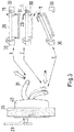
- Fig. 2
- ein Türblatt mit eingebauter Schließvorrichtung und vorgehaltenem Schließblech in seitlicher Ansicht,
- Fig. 3
- das Funktionsschema eines Hebels auf der Seite des Führerraums,
- Fig. 1a
- a locking device and a striking plate in the closed state of a door,
- Fig. 1
- b a locking device when a door is open,
- Fig. 1c
- a locking device and a striking plate when pulling back the tongue to open the door,
- Fig. 2
- a side view of a door leaf with built-in locking device and locking plate,
- Fig. 3
- the operating diagram of a lever on the side of the cab,
Die
Die linke Darstellung des Schließblechs 8 zeigt eine Draufsicht auf das Schließblech aus einer leicht schrägen Perspektive. Zu sehen sind eine erste Öffnung A, die auch als Schlossfalle bezeichnet wird, und eine zweite Öffnung B, auch bezeichnet als Einreiberfalle. Ferner sind zwei Langlöcher 9 erkennbar, welche Schrauben (nicht gezeigt) aufnehmen können, mit denen das Schließblech 8 an einer Türzarge befestigt werden kann. Der rechte Teil der
Die
Des Weiteren ist in der
Zum Schließen der Tür wird entweder von einer Seite M gedrückt, die bei der bevorzugten Verwendung der Tür die Maschinenraumseite einer Lokomotive ist, oder von einer zweiten Seite F gezogen, die bei der bevorzugten Verwendung der Tür die Führerraumseite einer Lokomotive ist. Das Drücken von Seiten des Maschinenraums gegen das Türblatt ist in der
Beim Schließen der Tür wird auch der Auslöser 4 in das Gehäuse 10 bewegt, gegen die Kraft der Feder 12.When the door is closed, the
Der geschlossene Zustand der Tür ist sowohl in der
Durch die relative Bewegung von Auslöser 4 und Schließzunge 1 wird ein Auslenken des Hebels 5 bewirkt, wie in der
Der Einreiber wird durch Betätigung des Hebels 31 gedreht, wie in der
In der gezeigten Ausführungsform verjüngt sich die zweite Öffnung B nach unten und der Riegel 11 der Anpresseinrichtung wird von oben in die Einreiberfalle hinein gedreht. Der Rand 33 verläuft schräg nach unten in Richtung der Schließrichtung des Türblatts, wobei die Schließrichtung durch die Pfeile M und F (
Die
In der
Durch die Rückstellung des Hebels 5 wird die Sperrklinke 3 freigegeben und gelangt über eine Rückstellfeder (nicht gezeigt) in die Ausgangstellung zurück.By resetting the
Die
In der gezeigten Ausführungsform kann der Türbetätigungshebel 31 (nachfolgend abgekürzt als Hebel 31) in drei verschiedene Stellungen gebracht werden: Die erste Stellung X, die zweite Stellung Y und die dritte Stellung Z, die auch als Neutralstellung bezeichnet werden kann.In the embodiment shown, the door operating lever 31 (hereinafter abbreviated as lever 31) can be brought into three different positions: the first position X, the second position Y and the third position Z, which can also be referred to as the neutral position.
In der gestrichelt dargestellten Neutralstellung Z kann bei geöffneter Tür von Seiten des Fahrerraums an dem Hebel 31 gezogen werden, wodurch das Türblatt schließt und die Schließzunge 1 zunächst an die Zarge 30 anschlägt, dann in die Schließvorrichtung hinein gedrückt wird und schließlich in die Schlossfalle (erste Öffnung A) einfällt. Bei diesem Vorgang ist ein Widerstand der rückfedernden Hohlkammerdichtungen 27 (
Nach Schließen der Tür wird die Tür druckdicht verriegelt, indem der Hebel 31 aus der gestrichelt dargestellten Neutralstellung Z nach oben in die erste Stellung X gezogen wird, wie durch den schräg nach oben verlaufenden Pfeil angedeutet. Durch Stellen des Hebels 31 in die Stellung X wird der Riegel 11 durch eine Drehbewegung des Einreibers 2 in die zweite Öffnung B mit einem schräg verlaufenden Rand 33 eingeführt und das Türblatt 26 gegen die Türzarge 30 gepresst, wobei die Dichtungen 27 die Tür druckdicht abschließen. Die Stellung des Einreibers 2 und des Hebels 11, die durch Stellen des Hebels 31 in die Stellung X hervorgerufen wird, ist in der
Zur Entriegelung und zum Öffnen der Tür von Seiten des Fahrerraums wird der Hebel 31 aus der ersten Stellung X in die zweite Stellung Y gebracht, wobei der Hebel 31 nach unten in Richtung des Türblatts 26 gedrückt wird. Bei dieser Bewegung wird die Neutralstellung Z durchlaufen. Beim Bewegen des Hebels 31 von der ersten Stellung X in die Neutralstellung Z wird der Riegel 11 des Einreibers 2 durch Einwirkung des Hebels 31 wieder aus der Einreiberfalle B herausgedreht. In der Neutralstellung wird die Schließzunge 1 noch nicht durch den Riegel 11 zurückgedrückt, wie in der
Von Seiten des Fahrerraums ist das Öffnen der Tür durch eine Bewegung des Hebels 31 realisierbar. Der Fahrer muss nur gegen den Hebel 31 drücken und ihn in die Stellung Y bringen, wobei durch die Drückbewegung gleichzeitig die Tür geöffnet wird. Die Betätigung ist durch die Bügelform des Hebels erleichtert und kann schnell vollzogen werden, was bei Notfällen eine schnelle Flucht des Fahrers aus dem Fahrerraum sicherstellen soll. Daher wird der Hebel 31 in der gezeigten Bügelform auch als "Panikbalken" bezeichnet.From the driver's side, the door can be opened by moving the
Vorzugsweise ist der Hebel 31 mit einer Rückstellfeder versehen (nicht gezeigt), die den Hebel 31 nach Öffnen der Tür aus der zweiten Stellung Y in die Neutralstellung Z zurückstellt.The
Claims (9)
- A closing device (7) for vehicle doors, in particular for pressure-sealed doors on the inside of rail vehicles, comprising:- a locking tongue (1), which can be inserted into a first opening (A) arranged on a door frame (30);- a trigger (4), which is movable relative to the locking tongue (1) during insertion of the locking tongue (1) into the first opening (A) and which is used in cooperation with the locking tongue (1) to transfer the pressing unit (2) from the blocked into the unblocked state,
wherein
the pressing unit (2) being transferrable from the blocked state into the unblocked state by the relative movement of the trigger (4) and the locking tongue (1) during insertion of the locking tongue into the first opening (A), and the bolt (11) of the pressing device being insertable into the second opening (B),
characterized in that- a pressing unit (2), which can occupy an unblocked and a blocked state, wherein, in the unblocked state, a bolt (11) of the pressing unit (2) can be inserted into a second opening (B) arranged in the door frame (30) with an obliquely extending edge, so that a door leaf (26) is pressed against the door frame by the movement of the bolt along the obliquely extending edge and, in the blocked state, the bolt (11) cannot be inserted into the second opening (B); and- a door actuating lever (31), which is coupled to the pressing unit (2) and can be moved into a first position, wherein during the movement of the door actuating lever (31) into the first position, the bolt (11) of the pressing unit (2) being inserted into the second opening (B) with an obliquely extending edge, and the door leaf (26) being pressed against the door frame (30) by the movement of the bolt along the obliquely extending edge. - The closing device according to claim 1, wherein the trigger (4) and the locking tongue (1) are connected to a mechanical system that is moved by the relative movement of the trigger (4) and the locking tongue (1) and transfers the pressing unit (2) from the blocked state into the unblocked state.
- The closing device according to any one of the preceding claims, comprising a blocking/unblocking unit (3, 5), which is movably coupled to the locking tongue (1) and to the trigger (4) so that the blocking/unblocking unit (3, 5) acts on the pressing unit (2) as a result of the relative movement of the locking tongue (1) and the trigger (4) and transfers the pressing unit (2) from the blocked state into the unblocked state.
- The closing device according to claim 3, wherein the blocking/unblocking unit (3, 5) comprises the following elements:- a blocking unit (3), which, in a first position, holds the pressing unit (2) in the blocked state, so that the insertion of the bolt (11) of the pressing unit (2) into the second opening (B) is prevented, and, in a second position, releases the pressing unit (2) into the unblocked state, so that the insertion of the bolt (11) into the second opening (B) is enabled; and- an unblocking unit (5), which is movably coupled to the locking tongue (1) and to the trigger (4) and can be moved during the insertion of the locking tongue (1) into the first opening (A) as a result of the relative movement of the locking tongue (1) and the trigger (4), which can act on the blocking unit (3) and move the blocking unit from the first position into the second position.
- The closing device according to claim 4, wherein the unblocking unit (5) is a lever, which is hinged on the locking tongue (1) and the trigger (4), so that the lever can be displaced by a relative movement of the locking tongue and the trigger and can act on the blocking unit (3).
- The closing device according to any one of the preceding claims, wherein the trigger (4) is movable parallel to the locking tongue (1), the trigger (4) not being movable by the same distance as the locking tongue at the time at which the locking tongue (1) engages in the first opening (A) arranged on the door frame (30), so that a relative movement between the trigger and the locking tongue can be created by the engagement of the locking tongue (1) in the first opening (A).
- The closing device according to claim 1, wherein the door actuating lever (31) can be moved into a second position, wherein the bolt (11) of the pressing unit (2) being moved out of the second opening (B) arranged in the door frame (30) during the movement of the door actuating lever (31) into the second position, and the locking tongue (1) and the pressing unit (2) being designed in such a way that the pressing unit (2) acts on the locking tongue (1) during the movement of the door actuating lever into the second position and moves the locking tongue out of the first opening (A).
- The closing device according to any one of the preceding claims, furthermore comprising a strike plate (8) for attachment to a door frame (30), which comprises the first opening (A) and the second opening (B).
- A rail vehicle, comprising a door, in particular a pressure-sealed door, including a closing device according to any one of claims 1 to 8.
Priority Applications (1)
| Application Number | Priority Date | Filing Date | Title |
|---|---|---|---|
| PL12180698T PL2559834T3 (en) | 2011-08-18 | 2012-08-16 | Closing device for vehicle doors |
Applications Claiming Priority (1)
| Application Number | Priority Date | Filing Date | Title |
|---|---|---|---|
| DE102011081189A DE102011081189A1 (en) | 2011-08-18 | 2011-08-18 | Locking device for vehicle doors |
Publications (3)
| Publication Number | Publication Date |
|---|---|
| EP2559834A2 EP2559834A2 (en) | 2013-02-20 |
| EP2559834A3 EP2559834A3 (en) | 2017-08-23 |
| EP2559834B1 true EP2559834B1 (en) | 2020-01-01 |
Family
ID=46934412
Family Applications (1)
| Application Number | Title | Priority Date | Filing Date |
|---|---|---|---|
| EP12180698.8A Active EP2559834B1 (en) | 2011-08-18 | 2012-08-16 | Closing device for vehicle doors |
Country Status (4)
| Country | Link |
|---|---|
| EP (1) | EP2559834B1 (en) |
| DE (1) | DE102011081189A1 (en) |
| ES (1) | ES2780380T3 (en) |
| PL (1) | PL2559834T3 (en) |
Family Cites Families (11)
| Publication number | Priority date | Publication date | Assignee | Title |
|---|---|---|---|---|
| GB191311932A (en) * | 1913-05-22 | 1914-02-05 | William Ralston Carson | Improved Fastenings for Doors, Windows and the like. |
| FR572617A (en) * | 1923-11-03 | 1924-06-10 | Cooler lock | |
| DE453492C (en) * | 1925-12-25 | 1927-12-07 | Brown Boveri & Cie Akt Ges Abt | Lock for doors of refrigerators and like |
| GB519411A (en) * | 1939-05-05 | 1940-03-26 | Eugen Moessmer | Improvements in or relating to fastening means for doors, windows or the like |
| DE3908688C2 (en) * | 1989-03-16 | 1997-06-12 | Gruenzweig & Hartmann Montage | Mortise or case lock for soundproof doors |
| DE3937154A1 (en) * | 1989-11-08 | 1991-05-16 | Kapolnek Schall Und Schwingung | Lock for sound proof door - includes sprung CAM to prevent being left open with lock bolt in extended position |
| ES2115191T3 (en) * | 1994-02-21 | 1998-06-16 | Hellmuller & Zingg Ag | DOOR LOCK. |
| GB2297794B (en) * | 1995-02-10 | 1998-12-30 | Hoong Thye Eldon Lee | Closure mechanism for airtight doors |
| AT407549B (en) * | 1999-02-24 | 2001-04-25 | Kaba Gege Gmbh | LOCK WITH PUSH-OPERABLE AND LOCKABLE MAIN CASE |
| GB2386393A (en) * | 2002-03-15 | 2003-09-17 | Surelock Mcgill Ltd | Bolting mechanism |
| DE102010005261B4 (en) * | 2010-01-20 | 2012-02-09 | Carl Wilhelm Cleff Gmbh & Co Kg | Lock for a rail vehicle door |
-
2011
- 2011-08-18 DE DE102011081189A patent/DE102011081189A1/en not_active Ceased
-
2012
- 2012-08-16 EP EP12180698.8A patent/EP2559834B1/en active Active
- 2012-08-16 PL PL12180698T patent/PL2559834T3/en unknown
- 2012-08-16 ES ES12180698T patent/ES2780380T3/en active Active
Non-Patent Citations (1)
| Title |
|---|
| None * |
Also Published As
| Publication number | Publication date |
|---|---|
| ES2780380T3 (en) | 2020-08-25 |
| DE102011081189A1 (en) | 2013-02-21 |
| PL2559834T3 (en) | 2020-06-29 |
| EP2559834A2 (en) | 2013-02-20 |
| EP2559834A3 (en) | 2017-08-23 |
Similar Documents
| Publication | Publication Date | Title |
|---|---|---|
| EP1932989B1 (en) | Locking device for doors, windows or similar, in particular an espagnolette lock with panic function and multi-point locking | |
| EP1178171B1 (en) | Locking device for motor vehicle doors | |
| EP2569498B1 (en) | Grip device, in particular for a vehicle | |
| EP2845972A2 (en) | Motor vehicle lock | |
| DE102009029023A1 (en) | Lock for motor vehicle, has locking gear comprising rotary latch for retaining closing pin and ratchet pawl, where ratchet pawl is provided with rotatably mounted carrier handle and closing handle that is connected by joint | |
| EP3372757A1 (en) | Locking unit for a locking system of a door | |
| EP2157396B1 (en) | Vehicle door for armoured vehicles with an anti-mine protective bolt | |
| EP0521262A1 (en) | Lock | |
| EP1408187B1 (en) | Device for operating a lock for doors, flaps or similar, in particular on vehicles | |
| WO2016113044A1 (en) | Lock | |
| EP2706174B1 (en) | Lock for a door | |
| DE202005000939U1 (en) | Locking arrangement for door or window with drive rods 30 connecting auxiliary locks to main lock has pressure knob on main lock with pivoting lever moving bolt and drive rods | |
| EP2339096B1 (en) | Connecting rod lock with panic function and multiple locking | |
| DE102009050077A1 (en) | Vehicle lock, has closing catch engaging at rotary latch for implementing closing operation, and mechanism carrying out displacement of closing catch into external engaging position during reaching closing position of latch | |
| EP0634543A1 (en) | Combination lock with a rotating knob, a cam disc and a lever | |
| EP2754798B1 (en) | Door locking device for a door with at least one door leaf | |
| DE19808374B4 (en) | Device for locking a cover in the manner of a body hood of a motor vehicle | |
| DE202007016091U1 (en) | Espagnolette | |
| DE2839760A1 (en) | LOCKING DEVICE, IN PARTICULAR FOR DOORS OR WINDOWS | |
| DE102015000606A1 (en) | Locking device for a pivotally mounted wing | |
| EP2559834B1 (en) | Closing device for vehicle doors | |
| EP3628801B1 (en) | Lock device for a door and a method for opening a door | |
| DE10339542B4 (en) | Motor vehicle door lock | |
| DE102010053179A1 (en) | Motor vehicle door lock is provided with locking units and locking bolt, where release lever units are provided for locking units | |
| DE102004036655A1 (en) | Device for automatic closing of vehicle door has drive, which is operated by shiftable carrier with safety device, which prevents door from automatic closing in case of obstacle in path of door |
Legal Events
| Date | Code | Title | Description |
|---|---|---|---|
| PUAI | Public reference made under article 153(3) epc to a published international application that has entered the european phase |
Free format text: ORIGINAL CODE: 0009012 |
|
| AK | Designated contracting states |
Kind code of ref document: A2 Designated state(s): AL AT BE BG CH CY CZ DE DK EE ES FI FR GB GR HR HU IE IS IT LI LT LU LV MC MK MT NL NO PL PT RO RS SE SI SK SM TR |
|
| AX | Request for extension of the european patent |
Extension state: BA ME |
|
| PUAL | Search report despatched |
Free format text: ORIGINAL CODE: 0009013 |
|
| AK | Designated contracting states |
Kind code of ref document: A3 Designated state(s): AL AT BE BG CH CY CZ DE DK EE ES FI FR GB GR HR HU IE IS IT LI LT LU LV MC MK MT NL NO PL PT RO RS SE SI SK SM TR |
|
| AX | Request for extension of the european patent |
Extension state: BA ME |
|
| RIC1 | Information provided on ipc code assigned before grant |
Ipc: E05B 65/18 00000000ALI20170718BHEP Ipc: E05B 63/18 20060101ALI20170718BHEP Ipc: E05B 59/00 20060101ALI20170718BHEP Ipc: E05B 15/00 20060101ALI20170718BHEP Ipc: E05B 65/10 20060101ALI20170718BHEP Ipc: E05B 17/00 20060101AFI20170718BHEP |
|
| STAA | Information on the status of an ep patent application or granted ep patent |
Free format text: STATUS: REQUEST FOR EXAMINATION WAS MADE |
|
| 17P | Request for examination filed |
Effective date: 20180222 |
|
| RBV | Designated contracting states (corrected) |
Designated state(s): AL AT BE BG CH CY CZ DE DK EE ES FI FR GB GR HR HU IE IS IT LI LT LU LV MC MK MT NL NO PL PT RO RS SE SI SK SM TR |
|
| RIC1 | Information provided on ipc code assigned before grant |
Ipc: E05B 83/36 20140101ALI20190626BHEP Ipc: E05B 63/18 20060101ALI20190626BHEP Ipc: E05B 59/00 20060101ALI20190626BHEP Ipc: E05B 17/00 20060101AFI20190626BHEP Ipc: E05B 15/00 20060101ALI20190626BHEP Ipc: E05B 65/10 20060101ALI20190626BHEP Ipc: E05B 65/00 20060101ALI20190626BHEP |
|
| GRAP | Despatch of communication of intention to grant a patent |
Free format text: ORIGINAL CODE: EPIDOSNIGR1 |
|
| STAA | Information on the status of an ep patent application or granted ep patent |
Free format text: STATUS: GRANT OF PATENT IS INTENDED |
|
| INTG | Intention to grant announced |
Effective date: 20190805 |
|
| GRAS | Grant fee paid |
Free format text: ORIGINAL CODE: EPIDOSNIGR3 |
|
| GRAA | (expected) grant |
Free format text: ORIGINAL CODE: 0009210 |
|
| STAA | Information on the status of an ep patent application or granted ep patent |
Free format text: STATUS: THE PATENT HAS BEEN GRANTED |
|
| RAP1 | Party data changed (applicant data changed or rights of an application transferred) |
Owner name: BOMBARDIER TRANSPORTATION GMBH |
|
| AK | Designated contracting states |
Kind code of ref document: B1 Designated state(s): AL AT BE BG CH CY CZ DE DK EE ES FI FR GB GR HR HU IE IS IT LI LT LU LV MC MK MT NL NO PL PT RO RS SE SI SK SM TR |
|
| REG | Reference to a national code |
Ref country code: GB Ref legal event code: FG4D Free format text: NOT ENGLISH |
|
| REG | Reference to a national code |
Ref country code: AT Ref legal event code: REF Ref document number: 1219951 Country of ref document: AT Kind code of ref document: T Effective date: 20200115 Ref country code: CH Ref legal event code: EP |
|
| REG | Reference to a national code |
Ref country code: DE Ref legal event code: R096 Ref document number: 502012015652 Country of ref document: DE |
|
| REG | Reference to a national code |
Ref country code: IE Ref legal event code: FG4D Free format text: LANGUAGE OF EP DOCUMENT: GERMAN |
|
| REG | Reference to a national code |
Ref country code: CH Ref legal event code: NV Representative=s name: PATENTANWALT DIPL.-ING. (UNI.) WOLFGANG HEISEL, CH |
|
| REG | Reference to a national code |
Ref country code: NL Ref legal event code: FP |
|
| REG | Reference to a national code |
Ref country code: SE Ref legal event code: TRGR |
|
| REG | Reference to a national code |
Ref country code: LT Ref legal event code: MG4D |
|
| PG25 | Lapsed in a contracting state [announced via postgrant information from national office to epo] |
Ref country code: RS Free format text: LAPSE BECAUSE OF FAILURE TO SUBMIT A TRANSLATION OF THE DESCRIPTION OR TO PAY THE FEE WITHIN THE PRESCRIBED TIME-LIMIT Effective date: 20200101 Ref country code: LT Free format text: LAPSE BECAUSE OF FAILURE TO SUBMIT A TRANSLATION OF THE DESCRIPTION OR TO PAY THE FEE WITHIN THE PRESCRIBED TIME-LIMIT Effective date: 20200101 Ref country code: PT Free format text: LAPSE BECAUSE OF FAILURE TO SUBMIT A TRANSLATION OF THE DESCRIPTION OR TO PAY THE FEE WITHIN THE PRESCRIBED TIME-LIMIT Effective date: 20200527 Ref country code: FI Free format text: LAPSE BECAUSE OF FAILURE TO SUBMIT A TRANSLATION OF THE DESCRIPTION OR TO PAY THE FEE WITHIN THE PRESCRIBED TIME-LIMIT Effective date: 20200101 Ref country code: NO Free format text: LAPSE BECAUSE OF FAILURE TO SUBMIT A TRANSLATION OF THE DESCRIPTION OR TO PAY THE FEE WITHIN THE PRESCRIBED TIME-LIMIT Effective date: 20200401 |
|
| REG | Reference to a national code |
Ref country code: ES Ref legal event code: FG2A Ref document number: 2780380 Country of ref document: ES Kind code of ref document: T3 Effective date: 20200825 |
|
| PG25 | Lapsed in a contracting state [announced via postgrant information from national office to epo] |
Ref country code: GR Free format text: LAPSE BECAUSE OF FAILURE TO SUBMIT A TRANSLATION OF THE DESCRIPTION OR TO PAY THE FEE WITHIN THE PRESCRIBED TIME-LIMIT Effective date: 20200402 Ref country code: HR Free format text: LAPSE BECAUSE OF FAILURE TO SUBMIT A TRANSLATION OF THE DESCRIPTION OR TO PAY THE FEE WITHIN THE PRESCRIBED TIME-LIMIT Effective date: 20200101 Ref country code: IS Free format text: LAPSE BECAUSE OF FAILURE TO SUBMIT A TRANSLATION OF THE DESCRIPTION OR TO PAY THE FEE WITHIN THE PRESCRIBED TIME-LIMIT Effective date: 20200501 Ref country code: LV Free format text: LAPSE BECAUSE OF FAILURE TO SUBMIT A TRANSLATION OF THE DESCRIPTION OR TO PAY THE FEE WITHIN THE PRESCRIBED TIME-LIMIT Effective date: 20200101 Ref country code: BG Free format text: LAPSE BECAUSE OF FAILURE TO SUBMIT A TRANSLATION OF THE DESCRIPTION OR TO PAY THE FEE WITHIN THE PRESCRIBED TIME-LIMIT Effective date: 20200401 |
|
| REG | Reference to a national code |
Ref country code: DE Ref legal event code: R097 Ref document number: 502012015652 Country of ref document: DE |
|
| PG25 | Lapsed in a contracting state [announced via postgrant information from national office to epo] |
Ref country code: RO Free format text: LAPSE BECAUSE OF FAILURE TO SUBMIT A TRANSLATION OF THE DESCRIPTION OR TO PAY THE FEE WITHIN THE PRESCRIBED TIME-LIMIT Effective date: 20200101 Ref country code: DK Free format text: LAPSE BECAUSE OF FAILURE TO SUBMIT A TRANSLATION OF THE DESCRIPTION OR TO PAY THE FEE WITHIN THE PRESCRIBED TIME-LIMIT Effective date: 20200101 Ref country code: SK Free format text: LAPSE BECAUSE OF FAILURE TO SUBMIT A TRANSLATION OF THE DESCRIPTION OR TO PAY THE FEE WITHIN THE PRESCRIBED TIME-LIMIT Effective date: 20200101 Ref country code: EE Free format text: LAPSE BECAUSE OF FAILURE TO SUBMIT A TRANSLATION OF THE DESCRIPTION OR TO PAY THE FEE WITHIN THE PRESCRIBED TIME-LIMIT Effective date: 20200101 Ref country code: SM Free format text: LAPSE BECAUSE OF FAILURE TO SUBMIT A TRANSLATION OF THE DESCRIPTION OR TO PAY THE FEE WITHIN THE PRESCRIBED TIME-LIMIT Effective date: 20200101 |
|
| PLBE | No opposition filed within time limit |
Free format text: ORIGINAL CODE: 0009261 |
|
| STAA | Information on the status of an ep patent application or granted ep patent |
Free format text: STATUS: NO OPPOSITION FILED WITHIN TIME LIMIT |
|
| 26N | No opposition filed |
Effective date: 20201002 |
|
| PG25 | Lapsed in a contracting state [announced via postgrant information from national office to epo] |
Ref country code: SI Free format text: LAPSE BECAUSE OF FAILURE TO SUBMIT A TRANSLATION OF THE DESCRIPTION OR TO PAY THE FEE WITHIN THE PRESCRIBED TIME-LIMIT Effective date: 20200101 |
|
| PG25 | Lapsed in a contracting state [announced via postgrant information from national office to epo] |
Ref country code: MC Free format text: LAPSE BECAUSE OF FAILURE TO SUBMIT A TRANSLATION OF THE DESCRIPTION OR TO PAY THE FEE WITHIN THE PRESCRIBED TIME-LIMIT Effective date: 20200101 |
|
| GBPC | Gb: european patent ceased through non-payment of renewal fee |
Effective date: 20200816 |
|
| PG25 | Lapsed in a contracting state [announced via postgrant information from national office to epo] |
Ref country code: LU Free format text: LAPSE BECAUSE OF NON-PAYMENT OF DUE FEES Effective date: 20200816 |
|
| REG | Reference to a national code |
Ref country code: BE Ref legal event code: MM Effective date: 20200831 |
|
| PG25 | Lapsed in a contracting state [announced via postgrant information from national office to epo] |
Ref country code: BE Free format text: LAPSE BECAUSE OF NON-PAYMENT OF DUE FEES Effective date: 20200831 Ref country code: GB Free format text: LAPSE BECAUSE OF NON-PAYMENT OF DUE FEES Effective date: 20200816 Ref country code: IE Free format text: LAPSE BECAUSE OF NON-PAYMENT OF DUE FEES Effective date: 20200816 |
|
| PG25 | Lapsed in a contracting state [announced via postgrant information from national office to epo] |
Ref country code: TR Free format text: LAPSE BECAUSE OF FAILURE TO SUBMIT A TRANSLATION OF THE DESCRIPTION OR TO PAY THE FEE WITHIN THE PRESCRIBED TIME-LIMIT Effective date: 20200101 Ref country code: MT Free format text: LAPSE BECAUSE OF FAILURE TO SUBMIT A TRANSLATION OF THE DESCRIPTION OR TO PAY THE FEE WITHIN THE PRESCRIBED TIME-LIMIT Effective date: 20200101 Ref country code: CY Free format text: LAPSE BECAUSE OF FAILURE TO SUBMIT A TRANSLATION OF THE DESCRIPTION OR TO PAY THE FEE WITHIN THE PRESCRIBED TIME-LIMIT Effective date: 20200101 |
|
| PG25 | Lapsed in a contracting state [announced via postgrant information from national office to epo] |
Ref country code: MK Free format text: LAPSE BECAUSE OF FAILURE TO SUBMIT A TRANSLATION OF THE DESCRIPTION OR TO PAY THE FEE WITHIN THE PRESCRIBED TIME-LIMIT Effective date: 20200101 Ref country code: AL Free format text: LAPSE BECAUSE OF FAILURE TO SUBMIT A TRANSLATION OF THE DESCRIPTION OR TO PAY THE FEE WITHIN THE PRESCRIBED TIME-LIMIT Effective date: 20200101 |
|
| P01 | Opt-out of the competence of the unified patent court (upc) registered |
Effective date: 20230822 |
|
| PGFP | Annual fee paid to national office [announced via postgrant information from national office to epo] |
Ref country code: NL Payment date: 20230821 Year of fee payment: 12 |
|
| PGFP | Annual fee paid to national office [announced via postgrant information from national office to epo] |
Ref country code: IT Payment date: 20230825 Year of fee payment: 12 Ref country code: CZ Payment date: 20230807 Year of fee payment: 12 Ref country code: CH Payment date: 20230902 Year of fee payment: 12 Ref country code: AT Payment date: 20230822 Year of fee payment: 12 |
|
| PGFP | Annual fee paid to national office [announced via postgrant information from national office to epo] |
Ref country code: SE Payment date: 20230821 Year of fee payment: 12 Ref country code: PL Payment date: 20230811 Year of fee payment: 12 Ref country code: FR Payment date: 20230824 Year of fee payment: 12 Ref country code: DE Payment date: 20230821 Year of fee payment: 12 |
|
| PGFP | Annual fee paid to national office [announced via postgrant information from national office to epo] |
Ref country code: ES Payment date: 20231027 Year of fee payment: 12 |