EP2558342B1 - Verfahren zum betreiben eines kraftfahrzeugs mit zumindest zwei antrieben sowie kraftfahrzeug mit zumindest zwei antrieben - Google Patents
Verfahren zum betreiben eines kraftfahrzeugs mit zumindest zwei antrieben sowie kraftfahrzeug mit zumindest zwei antrieben Download PDFInfo
- Publication number
- EP2558342B1 EP2558342B1 EP11712178.0A EP11712178A EP2558342B1 EP 2558342 B1 EP2558342 B1 EP 2558342B1 EP 11712178 A EP11712178 A EP 11712178A EP 2558342 B1 EP2558342 B1 EP 2558342B1
- Authority
- EP
- European Patent Office
- Prior art keywords
- control unit
- torque
- motor vehicle
- max
- sub
- Prior art date
- Legal status (The legal status is an assumption and is not a legal conclusion. Google has not performed a legal analysis and makes no representation as to the accuracy of the status listed.)
- Not-in-force
Links
Images

Classifications
-
- B—PERFORMING OPERATIONS; TRANSPORTING
- B60—VEHICLES IN GENERAL
- B60W—CONJOINT CONTROL OF VEHICLE SUB-UNITS OF DIFFERENT TYPE OR DIFFERENT FUNCTION; CONTROL SYSTEMS SPECIALLY ADAPTED FOR HYBRID VEHICLES; ROAD VEHICLE DRIVE CONTROL SYSTEMS FOR PURPOSES NOT RELATED TO THE CONTROL OF A PARTICULAR SUB-UNIT
- B60W50/00—Details of control systems for road vehicle drive control not related to the control of a particular sub-unit, e.g. process diagnostic or vehicle driver interfaces
- B60W50/0098—Details of control systems ensuring comfort, safety or stability not otherwise provided for
-
- B—PERFORMING OPERATIONS; TRANSPORTING
- B60—VEHICLES IN GENERAL
- B60K—ARRANGEMENT OR MOUNTING OF PROPULSION UNITS OR OF TRANSMISSIONS IN VEHICLES; ARRANGEMENT OR MOUNTING OF PLURAL DIVERSE PRIME-MOVERS IN VEHICLES; AUXILIARY DRIVES FOR VEHICLES; INSTRUMENTATION OR DASHBOARDS FOR VEHICLES; ARRANGEMENTS IN CONNECTION WITH COOLING, AIR INTAKE, GAS EXHAUST OR FUEL SUPPLY OF PROPULSION UNITS IN VEHICLES
- B60K6/00—Arrangement or mounting of plural diverse prime-movers for mutual or common propulsion, e.g. hybrid propulsion systems comprising electric motors and internal combustion engines
- B60K6/20—Arrangement or mounting of plural diverse prime-movers for mutual or common propulsion, e.g. hybrid propulsion systems comprising electric motors and internal combustion engines the prime-movers consisting of electric motors and internal combustion engines, e.g. HEVs
- B60K6/42—Arrangement or mounting of plural diverse prime-movers for mutual or common propulsion, e.g. hybrid propulsion systems comprising electric motors and internal combustion engines the prime-movers consisting of electric motors and internal combustion engines, e.g. HEVs characterised by the architecture of the hybrid electric vehicle
- B60K6/44—Series-parallel type
- B60K6/448—Electrical distribution type
-
- B—PERFORMING OPERATIONS; TRANSPORTING
- B60—VEHICLES IN GENERAL
- B60K—ARRANGEMENT OR MOUNTING OF PROPULSION UNITS OR OF TRANSMISSIONS IN VEHICLES; ARRANGEMENT OR MOUNTING OF PLURAL DIVERSE PRIME-MOVERS IN VEHICLES; AUXILIARY DRIVES FOR VEHICLES; INSTRUMENTATION OR DASHBOARDS FOR VEHICLES; ARRANGEMENTS IN CONNECTION WITH COOLING, AIR INTAKE, GAS EXHAUST OR FUEL SUPPLY OF PROPULSION UNITS IN VEHICLES
- B60K6/00—Arrangement or mounting of plural diverse prime-movers for mutual or common propulsion, e.g. hybrid propulsion systems comprising electric motors and internal combustion engines
- B60K6/20—Arrangement or mounting of plural diverse prime-movers for mutual or common propulsion, e.g. hybrid propulsion systems comprising electric motors and internal combustion engines the prime-movers consisting of electric motors and internal combustion engines, e.g. HEVs
- B60K6/50—Architecture of the driveline characterised by arrangement or kind of transmission units
- B60K6/52—Driving a plurality of drive axles, e.g. four-wheel drive
-
- B—PERFORMING OPERATIONS; TRANSPORTING
- B60—VEHICLES IN GENERAL
- B60L—PROPULSION OF ELECTRICALLY-PROPELLED VEHICLES; SUPPLYING ELECTRIC POWER FOR AUXILIARY EQUIPMENT OF ELECTRICALLY-PROPELLED VEHICLES; ELECTRODYNAMIC BRAKE SYSTEMS FOR VEHICLES IN GENERAL; MAGNETIC SUSPENSION OR LEVITATION FOR VEHICLES; MONITORING OPERATING VARIABLES OF ELECTRICALLY-PROPELLED VEHICLES; ELECTRIC SAFETY DEVICES FOR ELECTRICALLY-PROPELLED VEHICLES
- B60L50/00—Electric propulsion with power supplied within the vehicle
- B60L50/10—Electric propulsion with power supplied within the vehicle using propulsion power supplied by engine-driven generators, e.g. generators driven by combustion engines
- B60L50/16—Electric propulsion with power supplied within the vehicle using propulsion power supplied by engine-driven generators, e.g. generators driven by combustion engines with provision for separate direct mechanical propulsion
-
- B—PERFORMING OPERATIONS; TRANSPORTING
- B60—VEHICLES IN GENERAL
- B60L—PROPULSION OF ELECTRICALLY-PROPELLED VEHICLES; SUPPLYING ELECTRIC POWER FOR AUXILIARY EQUIPMENT OF ELECTRICALLY-PROPELLED VEHICLES; ELECTRODYNAMIC BRAKE SYSTEMS FOR VEHICLES IN GENERAL; MAGNETIC SUSPENSION OR LEVITATION FOR VEHICLES; MONITORING OPERATING VARIABLES OF ELECTRICALLY-PROPELLED VEHICLES; ELECTRIC SAFETY DEVICES FOR ELECTRICALLY-PROPELLED VEHICLES
- B60L50/00—Electric propulsion with power supplied within the vehicle
- B60L50/50—Electric propulsion with power supplied within the vehicle using propulsion power supplied by batteries or fuel cells
- B60L50/60—Electric propulsion with power supplied within the vehicle using propulsion power supplied by batteries or fuel cells using power supplied by batteries
- B60L50/61—Electric propulsion with power supplied within the vehicle using propulsion power supplied by batteries or fuel cells using power supplied by batteries by batteries charged by engine-driven generators, e.g. series hybrid electric vehicles
-
- B—PERFORMING OPERATIONS; TRANSPORTING
- B60—VEHICLES IN GENERAL
- B60W—CONJOINT CONTROL OF VEHICLE SUB-UNITS OF DIFFERENT TYPE OR DIFFERENT FUNCTION; CONTROL SYSTEMS SPECIALLY ADAPTED FOR HYBRID VEHICLES; ROAD VEHICLE DRIVE CONTROL SYSTEMS FOR PURPOSES NOT RELATED TO THE CONTROL OF A PARTICULAR SUB-UNIT
- B60W10/00—Conjoint control of vehicle sub-units of different type or different function
- B60W10/04—Conjoint control of vehicle sub-units of different type or different function including control of propulsion units
- B60W10/06—Conjoint control of vehicle sub-units of different type or different function including control of propulsion units including control of combustion engines
-
- B—PERFORMING OPERATIONS; TRANSPORTING
- B60—VEHICLES IN GENERAL
- B60W—CONJOINT CONTROL OF VEHICLE SUB-UNITS OF DIFFERENT TYPE OR DIFFERENT FUNCTION; CONTROL SYSTEMS SPECIALLY ADAPTED FOR HYBRID VEHICLES; ROAD VEHICLE DRIVE CONTROL SYSTEMS FOR PURPOSES NOT RELATED TO THE CONTROL OF A PARTICULAR SUB-UNIT
- B60W10/00—Conjoint control of vehicle sub-units of different type or different function
- B60W10/04—Conjoint control of vehicle sub-units of different type or different function including control of propulsion units
- B60W10/08—Conjoint control of vehicle sub-units of different type or different function including control of propulsion units including control of electric propulsion units, e.g. motors or generators
-
- B—PERFORMING OPERATIONS; TRANSPORTING
- B60—VEHICLES IN GENERAL
- B60W—CONJOINT CONTROL OF VEHICLE SUB-UNITS OF DIFFERENT TYPE OR DIFFERENT FUNCTION; CONTROL SYSTEMS SPECIALLY ADAPTED FOR HYBRID VEHICLES; ROAD VEHICLE DRIVE CONTROL SYSTEMS FOR PURPOSES NOT RELATED TO THE CONTROL OF A PARTICULAR SUB-UNIT
- B60W20/00—Control systems specially adapted for hybrid vehicles
- B60W20/10—Controlling the power contribution of each of the prime movers to meet required power demand
- B60W20/11—Controlling the power contribution of each of the prime movers to meet required power demand using model predictive control [MPC] strategies, i.e. control methods based on models predicting performance
-
- B—PERFORMING OPERATIONS; TRANSPORTING
- B60—VEHICLES IN GENERAL
- B60W—CONJOINT CONTROL OF VEHICLE SUB-UNITS OF DIFFERENT TYPE OR DIFFERENT FUNCTION; CONTROL SYSTEMS SPECIALLY ADAPTED FOR HYBRID VEHICLES; ROAD VEHICLE DRIVE CONTROL SYSTEMS FOR PURPOSES NOT RELATED TO THE CONTROL OF A PARTICULAR SUB-UNIT
- B60W30/00—Purposes of road vehicle drive control systems not related to the control of a particular sub-unit, e.g. of systems using conjoint control of vehicle sub-units
- B60W30/02—Control of vehicle driving stability
-
- B—PERFORMING OPERATIONS; TRANSPORTING
- B60—VEHICLES IN GENERAL
- B60W—CONJOINT CONTROL OF VEHICLE SUB-UNITS OF DIFFERENT TYPE OR DIFFERENT FUNCTION; CONTROL SYSTEMS SPECIALLY ADAPTED FOR HYBRID VEHICLES; ROAD VEHICLE DRIVE CONTROL SYSTEMS FOR PURPOSES NOT RELATED TO THE CONTROL OF A PARTICULAR SUB-UNIT
- B60W30/00—Purposes of road vehicle drive control systems not related to the control of a particular sub-unit, e.g. of systems using conjoint control of vehicle sub-units
- B60W30/18—Propelling the vehicle
- B60W30/188—Controlling power parameters of the driveline, e.g. determining the required power
-
- B—PERFORMING OPERATIONS; TRANSPORTING
- B60—VEHICLES IN GENERAL
- B60L—PROPULSION OF ELECTRICALLY-PROPELLED VEHICLES; SUPPLYING ELECTRIC POWER FOR AUXILIARY EQUIPMENT OF ELECTRICALLY-PROPELLED VEHICLES; ELECTRODYNAMIC BRAKE SYSTEMS FOR VEHICLES IN GENERAL; MAGNETIC SUSPENSION OR LEVITATION FOR VEHICLES; MONITORING OPERATING VARIABLES OF ELECTRICALLY-PROPELLED VEHICLES; ELECTRIC SAFETY DEVICES FOR ELECTRICALLY-PROPELLED VEHICLES
- B60L2240/00—Control parameters of input or output; Target parameters
- B60L2240/10—Vehicle control parameters
- B60L2240/12—Speed
-
- B—PERFORMING OPERATIONS; TRANSPORTING
- B60—VEHICLES IN GENERAL
- B60L—PROPULSION OF ELECTRICALLY-PROPELLED VEHICLES; SUPPLYING ELECTRIC POWER FOR AUXILIARY EQUIPMENT OF ELECTRICALLY-PROPELLED VEHICLES; ELECTRODYNAMIC BRAKE SYSTEMS FOR VEHICLES IN GENERAL; MAGNETIC SUSPENSION OR LEVITATION FOR VEHICLES; MONITORING OPERATING VARIABLES OF ELECTRICALLY-PROPELLED VEHICLES; ELECTRIC SAFETY DEVICES FOR ELECTRICALLY-PROPELLED VEHICLES
- B60L2240/00—Control parameters of input or output; Target parameters
- B60L2240/10—Vehicle control parameters
- B60L2240/14—Acceleration
- B60L2240/16—Acceleration longitudinal
-
- B—PERFORMING OPERATIONS; TRANSPORTING
- B60—VEHICLES IN GENERAL
- B60L—PROPULSION OF ELECTRICALLY-PROPELLED VEHICLES; SUPPLYING ELECTRIC POWER FOR AUXILIARY EQUIPMENT OF ELECTRICALLY-PROPELLED VEHICLES; ELECTRODYNAMIC BRAKE SYSTEMS FOR VEHICLES IN GENERAL; MAGNETIC SUSPENSION OR LEVITATION FOR VEHICLES; MONITORING OPERATING VARIABLES OF ELECTRICALLY-PROPELLED VEHICLES; ELECTRIC SAFETY DEVICES FOR ELECTRICALLY-PROPELLED VEHICLES
- B60L2240/00—Control parameters of input or output; Target parameters
- B60L2240/10—Vehicle control parameters
- B60L2240/14—Acceleration
- B60L2240/18—Acceleration lateral
-
- B—PERFORMING OPERATIONS; TRANSPORTING
- B60—VEHICLES IN GENERAL
- B60L—PROPULSION OF ELECTRICALLY-PROPELLED VEHICLES; SUPPLYING ELECTRIC POWER FOR AUXILIARY EQUIPMENT OF ELECTRICALLY-PROPELLED VEHICLES; ELECTRODYNAMIC BRAKE SYSTEMS FOR VEHICLES IN GENERAL; MAGNETIC SUSPENSION OR LEVITATION FOR VEHICLES; MONITORING OPERATING VARIABLES OF ELECTRICALLY-PROPELLED VEHICLES; ELECTRIC SAFETY DEVICES FOR ELECTRICALLY-PROPELLED VEHICLES
- B60L2240/00—Control parameters of input or output; Target parameters
- B60L2240/10—Vehicle control parameters
- B60L2240/22—Yaw angle
-
- B—PERFORMING OPERATIONS; TRANSPORTING
- B60—VEHICLES IN GENERAL
- B60L—PROPULSION OF ELECTRICALLY-PROPELLED VEHICLES; SUPPLYING ELECTRIC POWER FOR AUXILIARY EQUIPMENT OF ELECTRICALLY-PROPELLED VEHICLES; ELECTRODYNAMIC BRAKE SYSTEMS FOR VEHICLES IN GENERAL; MAGNETIC SUSPENSION OR LEVITATION FOR VEHICLES; MONITORING OPERATING VARIABLES OF ELECTRICALLY-PROPELLED VEHICLES; ELECTRIC SAFETY DEVICES FOR ELECTRICALLY-PROPELLED VEHICLES
- B60L2240/00—Control parameters of input or output; Target parameters
- B60L2240/10—Vehicle control parameters
- B60L2240/24—Steering angle
-
- B—PERFORMING OPERATIONS; TRANSPORTING
- B60—VEHICLES IN GENERAL
- B60L—PROPULSION OF ELECTRICALLY-PROPELLED VEHICLES; SUPPLYING ELECTRIC POWER FOR AUXILIARY EQUIPMENT OF ELECTRICALLY-PROPELLED VEHICLES; ELECTRODYNAMIC BRAKE SYSTEMS FOR VEHICLES IN GENERAL; MAGNETIC SUSPENSION OR LEVITATION FOR VEHICLES; MONITORING OPERATING VARIABLES OF ELECTRICALLY-PROPELLED VEHICLES; ELECTRIC SAFETY DEVICES FOR ELECTRICALLY-PROPELLED VEHICLES
- B60L2240/00—Control parameters of input or output; Target parameters
- B60L2240/40—Drive Train control parameters
- B60L2240/42—Drive Train control parameters related to electric machines
- B60L2240/421—Speed
-
- B—PERFORMING OPERATIONS; TRANSPORTING
- B60—VEHICLES IN GENERAL
- B60L—PROPULSION OF ELECTRICALLY-PROPELLED VEHICLES; SUPPLYING ELECTRIC POWER FOR AUXILIARY EQUIPMENT OF ELECTRICALLY-PROPELLED VEHICLES; ELECTRODYNAMIC BRAKE SYSTEMS FOR VEHICLES IN GENERAL; MAGNETIC SUSPENSION OR LEVITATION FOR VEHICLES; MONITORING OPERATING VARIABLES OF ELECTRICALLY-PROPELLED VEHICLES; ELECTRIC SAFETY DEVICES FOR ELECTRICALLY-PROPELLED VEHICLES
- B60L2240/00—Control parameters of input or output; Target parameters
- B60L2240/40—Drive Train control parameters
- B60L2240/42—Drive Train control parameters related to electric machines
- B60L2240/423—Torque
-
- B—PERFORMING OPERATIONS; TRANSPORTING
- B60—VEHICLES IN GENERAL
- B60L—PROPULSION OF ELECTRICALLY-PROPELLED VEHICLES; SUPPLYING ELECTRIC POWER FOR AUXILIARY EQUIPMENT OF ELECTRICALLY-PROPELLED VEHICLES; ELECTRODYNAMIC BRAKE SYSTEMS FOR VEHICLES IN GENERAL; MAGNETIC SUSPENSION OR LEVITATION FOR VEHICLES; MONITORING OPERATING VARIABLES OF ELECTRICALLY-PROPELLED VEHICLES; ELECTRIC SAFETY DEVICES FOR ELECTRICALLY-PROPELLED VEHICLES
- B60L2240/00—Control parameters of input or output; Target parameters
- B60L2240/40—Drive Train control parameters
- B60L2240/42—Drive Train control parameters related to electric machines
- B60L2240/425—Temperature
-
- B—PERFORMING OPERATIONS; TRANSPORTING
- B60—VEHICLES IN GENERAL
- B60L—PROPULSION OF ELECTRICALLY-PROPELLED VEHICLES; SUPPLYING ELECTRIC POWER FOR AUXILIARY EQUIPMENT OF ELECTRICALLY-PROPELLED VEHICLES; ELECTRODYNAMIC BRAKE SYSTEMS FOR VEHICLES IN GENERAL; MAGNETIC SUSPENSION OR LEVITATION FOR VEHICLES; MONITORING OPERATING VARIABLES OF ELECTRICALLY-PROPELLED VEHICLES; ELECTRIC SAFETY DEVICES FOR ELECTRICALLY-PROPELLED VEHICLES
- B60L2240/00—Control parameters of input or output; Target parameters
- B60L2240/40—Drive Train control parameters
- B60L2240/44—Drive Train control parameters related to combustion engines
- B60L2240/443—Torque
-
- B—PERFORMING OPERATIONS; TRANSPORTING
- B60—VEHICLES IN GENERAL
- B60L—PROPULSION OF ELECTRICALLY-PROPELLED VEHICLES; SUPPLYING ELECTRIC POWER FOR AUXILIARY EQUIPMENT OF ELECTRICALLY-PROPELLED VEHICLES; ELECTRODYNAMIC BRAKE SYSTEMS FOR VEHICLES IN GENERAL; MAGNETIC SUSPENSION OR LEVITATION FOR VEHICLES; MONITORING OPERATING VARIABLES OF ELECTRICALLY-PROPELLED VEHICLES; ELECTRIC SAFETY DEVICES FOR ELECTRICALLY-PROPELLED VEHICLES
- B60L2240/00—Control parameters of input or output; Target parameters
- B60L2240/40—Drive Train control parameters
- B60L2240/54—Drive Train control parameters related to batteries
- B60L2240/545—Temperature
-
- B—PERFORMING OPERATIONS; TRANSPORTING
- B60—VEHICLES IN GENERAL
- B60L—PROPULSION OF ELECTRICALLY-PROPELLED VEHICLES; SUPPLYING ELECTRIC POWER FOR AUXILIARY EQUIPMENT OF ELECTRICALLY-PROPELLED VEHICLES; ELECTRODYNAMIC BRAKE SYSTEMS FOR VEHICLES IN GENERAL; MAGNETIC SUSPENSION OR LEVITATION FOR VEHICLES; MONITORING OPERATING VARIABLES OF ELECTRICALLY-PROPELLED VEHICLES; ELECTRIC SAFETY DEVICES FOR ELECTRICALLY-PROPELLED VEHICLES
- B60L2260/00—Operating Modes
- B60L2260/20—Drive modes; Transition between modes
- B60L2260/28—Four wheel or all wheel drive
-
- B—PERFORMING OPERATIONS; TRANSPORTING
- B60—VEHICLES IN GENERAL
- B60W—CONJOINT CONTROL OF VEHICLE SUB-UNITS OF DIFFERENT TYPE OR DIFFERENT FUNCTION; CONTROL SYSTEMS SPECIALLY ADAPTED FOR HYBRID VEHICLES; ROAD VEHICLE DRIVE CONTROL SYSTEMS FOR PURPOSES NOT RELATED TO THE CONTROL OF A PARTICULAR SUB-UNIT
- B60W50/00—Details of control systems for road vehicle drive control not related to the control of a particular sub-unit, e.g. process diagnostic or vehicle driver interfaces
- B60W2050/0001—Details of the control system
- B60W2050/0002—Automatic control, details of type of controller or control system architecture
- B60W2050/0004—In digital systems, e.g. discrete-time systems involving sampling
- B60W2050/0006—Digital architecture hierarchy
-
- B—PERFORMING OPERATIONS; TRANSPORTING
- B60—VEHICLES IN GENERAL
- B60W—CONJOINT CONTROL OF VEHICLE SUB-UNITS OF DIFFERENT TYPE OR DIFFERENT FUNCTION; CONTROL SYSTEMS SPECIALLY ADAPTED FOR HYBRID VEHICLES; ROAD VEHICLE DRIVE CONTROL SYSTEMS FOR PURPOSES NOT RELATED TO THE CONTROL OF A PARTICULAR SUB-UNIT
- B60W2510/00—Input parameters relating to a particular sub-units
- B60W2510/24—Energy storage means
- B60W2510/242—Energy storage means for electrical energy
- B60W2510/244—Charge state
-
- B—PERFORMING OPERATIONS; TRANSPORTING
- B60—VEHICLES IN GENERAL
- B60W—CONJOINT CONTROL OF VEHICLE SUB-UNITS OF DIFFERENT TYPE OR DIFFERENT FUNCTION; CONTROL SYSTEMS SPECIALLY ADAPTED FOR HYBRID VEHICLES; ROAD VEHICLE DRIVE CONTROL SYSTEMS FOR PURPOSES NOT RELATED TO THE CONTROL OF A PARTICULAR SUB-UNIT
- B60W2510/00—Input parameters relating to a particular sub-units
- B60W2510/24—Energy storage means
- B60W2510/242—Energy storage means for electrical energy
- B60W2510/246—Temperature
-
- B—PERFORMING OPERATIONS; TRANSPORTING
- B60—VEHICLES IN GENERAL
- B60W—CONJOINT CONTROL OF VEHICLE SUB-UNITS OF DIFFERENT TYPE OR DIFFERENT FUNCTION; CONTROL SYSTEMS SPECIALLY ADAPTED FOR HYBRID VEHICLES; ROAD VEHICLE DRIVE CONTROL SYSTEMS FOR PURPOSES NOT RELATED TO THE CONTROL OF A PARTICULAR SUB-UNIT
- B60W2520/00—Input parameters relating to overall vehicle dynamics
- B60W2520/10—Longitudinal speed
- B60W2520/105—Longitudinal acceleration
-
- B—PERFORMING OPERATIONS; TRANSPORTING
- B60—VEHICLES IN GENERAL
- B60W—CONJOINT CONTROL OF VEHICLE SUB-UNITS OF DIFFERENT TYPE OR DIFFERENT FUNCTION; CONTROL SYSTEMS SPECIALLY ADAPTED FOR HYBRID VEHICLES; ROAD VEHICLE DRIVE CONTROL SYSTEMS FOR PURPOSES NOT RELATED TO THE CONTROL OF A PARTICULAR SUB-UNIT
- B60W2520/00—Input parameters relating to overall vehicle dynamics
- B60W2520/12—Lateral speed
- B60W2520/125—Lateral acceleration
-
- B—PERFORMING OPERATIONS; TRANSPORTING
- B60—VEHICLES IN GENERAL
- B60W—CONJOINT CONTROL OF VEHICLE SUB-UNITS OF DIFFERENT TYPE OR DIFFERENT FUNCTION; CONTROL SYSTEMS SPECIALLY ADAPTED FOR HYBRID VEHICLES; ROAD VEHICLE DRIVE CONTROL SYSTEMS FOR PURPOSES NOT RELATED TO THE CONTROL OF A PARTICULAR SUB-UNIT
- B60W2520/00—Input parameters relating to overall vehicle dynamics
- B60W2520/14—Yaw
-
- B—PERFORMING OPERATIONS; TRANSPORTING
- B60—VEHICLES IN GENERAL
- B60W—CONJOINT CONTROL OF VEHICLE SUB-UNITS OF DIFFERENT TYPE OR DIFFERENT FUNCTION; CONTROL SYSTEMS SPECIALLY ADAPTED FOR HYBRID VEHICLES; ROAD VEHICLE DRIVE CONTROL SYSTEMS FOR PURPOSES NOT RELATED TO THE CONTROL OF A PARTICULAR SUB-UNIT
- B60W2540/00—Input parameters relating to occupants
- B60W2540/18—Steering angle
-
- Y—GENERAL TAGGING OF NEW TECHNOLOGICAL DEVELOPMENTS; GENERAL TAGGING OF CROSS-SECTIONAL TECHNOLOGIES SPANNING OVER SEVERAL SECTIONS OF THE IPC; TECHNICAL SUBJECTS COVERED BY FORMER USPC CROSS-REFERENCE ART COLLECTIONS [XRACs] AND DIGESTS
- Y02—TECHNOLOGIES OR APPLICATIONS FOR MITIGATION OR ADAPTATION AGAINST CLIMATE CHANGE
- Y02T—CLIMATE CHANGE MITIGATION TECHNOLOGIES RELATED TO TRANSPORTATION
- Y02T10/00—Road transport of goods or passengers
- Y02T10/60—Other road transportation technologies with climate change mitigation effect
- Y02T10/62—Hybrid vehicles
-
- Y—GENERAL TAGGING OF NEW TECHNOLOGICAL DEVELOPMENTS; GENERAL TAGGING OF CROSS-SECTIONAL TECHNOLOGIES SPANNING OVER SEVERAL SECTIONS OF THE IPC; TECHNICAL SUBJECTS COVERED BY FORMER USPC CROSS-REFERENCE ART COLLECTIONS [XRACs] AND DIGESTS
- Y02—TECHNOLOGIES OR APPLICATIONS FOR MITIGATION OR ADAPTATION AGAINST CLIMATE CHANGE
- Y02T—CLIMATE CHANGE MITIGATION TECHNOLOGIES RELATED TO TRANSPORTATION
- Y02T10/00—Road transport of goods or passengers
- Y02T10/60—Other road transportation technologies with climate change mitigation effect
- Y02T10/64—Electric machine technologies in electromobility
-
- Y—GENERAL TAGGING OF NEW TECHNOLOGICAL DEVELOPMENTS; GENERAL TAGGING OF CROSS-SECTIONAL TECHNOLOGIES SPANNING OVER SEVERAL SECTIONS OF THE IPC; TECHNICAL SUBJECTS COVERED BY FORMER USPC CROSS-REFERENCE ART COLLECTIONS [XRACs] AND DIGESTS
- Y02—TECHNOLOGIES OR APPLICATIONS FOR MITIGATION OR ADAPTATION AGAINST CLIMATE CHANGE
- Y02T—CLIMATE CHANGE MITIGATION TECHNOLOGIES RELATED TO TRANSPORTATION
- Y02T10/00—Road transport of goods or passengers
- Y02T10/60—Other road transportation technologies with climate change mitigation effect
- Y02T10/70—Energy storage systems for electromobility, e.g. batteries
-
- Y—GENERAL TAGGING OF NEW TECHNOLOGICAL DEVELOPMENTS; GENERAL TAGGING OF CROSS-SECTIONAL TECHNOLOGIES SPANNING OVER SEVERAL SECTIONS OF THE IPC; TECHNICAL SUBJECTS COVERED BY FORMER USPC CROSS-REFERENCE ART COLLECTIONS [XRACs] AND DIGESTS
- Y02—TECHNOLOGIES OR APPLICATIONS FOR MITIGATION OR ADAPTATION AGAINST CLIMATE CHANGE
- Y02T—CLIMATE CHANGE MITIGATION TECHNOLOGIES RELATED TO TRANSPORTATION
- Y02T10/00—Road transport of goods or passengers
- Y02T10/60—Other road transportation technologies with climate change mitigation effect
- Y02T10/7072—Electromobility specific charging systems or methods for batteries, ultracapacitors, supercapacitors or double-layer capacitors
Definitions
- the invention relates to a method for operating a motor vehicle with at least two drives, in particular for different axes of the motor vehicle. It also concerns a motor vehicle.
- a method for operating a motor vehicle with two electric drives for different axes of the motor vehicle is in particular from US 2009/0118924 A1 known.
- the method makes use of a control unit.
- This receives inputs, eg. B. an input via which a certain torque is requested, as it results from the position of a driving or accelerator pedal (the same applies to a brake pedal). Further inputs come from a speed sensor and sensors, the parameters such. B. pressure and temperatures of components of the motor vehicle, in particular of the engine, and also affect the environment.
- the controller then sends control signals to actuators that drive the motors, e.g. As fuel injectors, a throttle valve, etc. It is determined a minimum and a maximum torque for each engine. Certain criteria are set up, distinguishing between three different cases. Finally, there is an allocation of an output torque to the individual motors.
- the DE 10 2004 049 324 A1 describes that in a hybrid vehicle depending on a pedal position of a first module of the driver's request is determined and a driver's request corresponding value for a drive torque is passed to a control unit, where further measurements such as driving speed, etc. are taken into account to calculate a degree of distribution, which corresponds to the ratio of the torque of the electric motor to the drive torque.
- This degree of distribution is forwarded to a control stage, which calculates a second degree of distribution according to vehicle dynamics functions. Both degrees of distribution are fed to a coordination stage which determines the final degree of distribution on the basis of motor limits.
- the WO 2010/031678 A1 discloses that for adjusting a motor drive device with two drive units, a total drive torque is first determined and subsequently from the torque distribution for the drive units is determined, with boundary conditions are taken into account from vehicle dynamics control systems. From this, a consumption-optimal torque distribution is then calculated taking into account, among other things, restrictions arising from the motor drive units. If this can not be realized, a feedback takes place so that a new calculation of the consumption-optimal torque distribution takes place.
- the known from the prior art method for operating a motor vehicle with two drives provide for an allocation of requested torque to the individual drives according to certain criteria such.
- the energy efficiency or the availability of electricity through a battery for an electric drive As the energy efficiency or the availability of electricity through a battery for an electric drive.
- the distribution of torque on individual axles of the motor vehicle also has a direct effect on the driving behavior of the motor vehicle. It is known torque for stabilization a motor vehicle to move from one axis to another axis, possibly also from one wheel of an axle to another wheel of an axle.
- a suitable motor vehicle is to be provided for this purpose.
- the object is achieved with regard to the method by a method having the features according to claim 1 and solved with respect to the motor vehicle by a motor vehicle with the features according to claim 6.
- the first control device thus initially, on the basis of the measured values, gives a set of combinations of respective partial torques for individual drive units (the individual drives or also for groups of drives, eg on an axis) and sends data signals for description of these combinations to a second control device.
- This second control device receives measured values of quantities of which second variables are different from those primary variables to which the measured values received by the first control device belong.
- the second control device selects at least one combination of respective partial torques for the individual drives (or groups of drives) from the group of combinations and sends data signals for describing this at least one combination to the first control device.
- the first control device then sets the partial torques for the individual drives; alternatively, it does so only for groups of drives or a group and a single drive.
- the second control device selects more than two combinations of respective partial torques for the individual drives, in the first control device again a selection is made from these several combinations selected by the second control device, specifically as a function of the measured values obtained by the first control device be received.
- the first control device makes a general specification
- the second control device then restricts the specification.
- the second control device may in particular have the task of regulating the stability of the vehicle.
- the first control device can then apply other criteria at least to a certain extent, but only after limiting its possibilities by the second control device.
- the second control device because it restricts the possibilities of the first control device, an important role.
- the limitation of the possibilities can in particular be such that in all remaining after the restriction possibilities of torque distribution is still provided for a sufficient stability of the vehicle.
- the first control device sets a bandwidth for the partial torques of at least one drive or for the partial torques of several such drives in total, which is limited by the second control device.
- the first control device transmits transmission information about a maximum and a minimum partial torque for at least one drive / a drive group to the second control device, and the second control device in response sends a return information about a maximum and Minimum partial torque for precisely this at least one drive / exactly this drive group to the first control device, optionally alternatively or additionally, a predetermined partial torque for this.
- a limitation in the bandwidth can then be defined so that at least for a time during operation of the motor vehicle (namely, in particular in a predetermined driving situation in which intervention of a suspension control is required - also called vehicle dynamics control) the maximum partial torque and / or the specified partial torque according to the return information, is smaller than the maximum part torque according to the transmission information; then there would be a limitation of the bandwidth from above.
- the minimum partial torque and / or the specified partial torque according to the return information may be greater than the minimum torque according to the transmission information; then the restriction is made from below. Both can be given in particular at the same time.
- the family of combinations then corresponds to all combinations in which the partial torque for the at least one drive lies between the minimum and the maximum partial torque. This set can be finite by a discretization, but in principle infinitely many values between the minimum and the maximum partial torque can be possible, so there can be infinitely many combinations of respective partial torques in this group.
- the second control device In order for the second control device to be able to make such a selection that increased stability of the motor vehicle is provided, it preferably receives measured values for a yaw rate of the motor vehicle, for a longitudinal acceleration of the motor vehicle and / or for a transverse acceleration of the motor vehicle and / or for a steering angle a steering handle and taken into account when selecting the at least one combination optionally at least one of these measured values directly. For certain values for the variables mentioned, it may be possible for the second control device to select all possible combinations from the group of combinations at once. Then an intervention of the suspension control is therefore not required.
- At least one drive is preferably an electric drive.
- the first control device receives measured values for a battery assigned to the electric drive, so that an electric drive is preferred over an internal combustion engine or an electric drive in order to increase the efficiency another electric drive is preferred when the battery of the preferred electric drive allows its operation for at least a certain period of time.
- the first controller may also receive readings relating to a speed of an engine and / or a temperature of the engine and / or a gear engaged gear and / or an operating mode.
- a voltage provided by it or the charge stored in it, its capacity to charge and a measured value describing its temperature can be received as measured values for the battery. These measured values can be evaluated according to specific criteria.
- the motor vehicle according to the invention has at least two (in particular electric) drives and a first control device for allocating torque to the individual drives and for transmitting corresponding request signals to these drives. It is characterized in that the first control device is coupled to a second control device, which in turn is coupled to at least one measuring device which is separate from the first control device, and wherein the second control device is adapted to a process (method) of the allocation from torque to the individual drives by exchanging data signals with the first control device in the sense of the method according to the invention and to take into account measured values of the at least one measuring device in the formation of emitted data signals (namely for their definition).
- Each controller may be provided by a separate controller or as software functionality (block) in a single controller.
- the invention provides two control devices, both equally involved in the allocation of torque to the individual drives. This makes it possible to assign one of the control devices with the task to provide stability of the motor vehicle, while the other control device can use other criteria, eg. B. energy efficiency.
- the at least one measuring device thus comprises a yaw rate sensor, a longitudinal acceleration sensor and / or a lateral acceleration sensor and / or means for measuring the steering angle to a steering handle, so that the second control device receives corresponding information about the stability of the vehicle.
- an internal combustion engine 12 is available as the drive; this drives a front axle 14 of the motor vehicle.
- an electric drive 16 is available, which is fed from a battery 18.
- the second electric drive is fed from the same battery 18.
- an accelerator pedal (“accelerator pedal") 28
- a driver can specify how fast the motor vehicle 10 should drive, with the aid of a brake pedal 30 can be braked.
- the motor vehicle 10 is steered by means of a steering wheel 32.
- an actuating element 34 a mode can be set.
- a control unit 36 determines which total torque is to be applied by the individual wheels 38 of the motor vehicle. It must be assigned, which partial torque by the internal combustion engine 12, by the electric drive 16 and by the electric drive 22 each is to raise. This allocation is performed by the control unit 36. For the determination of the total torque and the allocation control unit 36 receives the measured values, namely, the s position F of the accelerator pedal 28, the position s B of the brake pedal 30 and the position St of the operating member 34. In addition, information about the battery 18 provided, in particular information about the temperature T as well as information about the state of charge, symbolically marked L; L may be a voltage, an amount of the stored charge, or a measure of the aging of the battery. Task of the controller, which can also be referred to as a "drive manager" is the allocation of the partial torques to the individual drives 16 and 22 and the internal combustion engine 12 according to certain aspects such. B. energy efficiency.
- a second control unit 40 receives signals from a lateral acceleration sensor 42, a longitudinal acceleration sensor 44 and a yaw rate sensor 46 and knows the steering angle ⁇ . There are thus such information available that make a statement about the stable handling of the motor vehicle 10 on the road surface.
- the first controller 36 determines for this purpose in a conventional manner a total torque that is due to the driver requirements to apply to the four wheels 38. For this purpose, the input variables at the elements 28, 30, 32, 34, 18 and 26 are taken into account. At the same time, the speed of the wheels 38, the speed of the motor vehicle, a gear engaged in a gear, etc. can be used.
- the control unit 36 can now determine, based on the drives 16 and 22 or their battery 18 associated quantities to each of the drives 16, 22, which torque T min they can at least deliver, and which Torque T max they can deliver maximum. In addition, the controller 36 may determine a desired torque Tw.
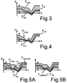
- the second controller 40 now receives the information regarding the quantities T min , T max and T W. It also receives readings related to elements 28, 30, 32, and 34. In addition, second controller 40 receives the readings from sensors 42, 44, and 46. Because of the latter, the second controller is capable of detecting such torques T from that in Figs Fig. 3 to exclude hatched drawn band in which the ride of the motor vehicle 10 would not be sufficiently stable. These excluded values are at the top or bottom of the band between T min and T max . In other words, the second controller sets new values T ' max and T' min indicating a restricted band as in Fig. 4 drawn hatched, defined.
- a desired torque T ' W is output, in which the drive of the motor vehicle has a desired stability state, in particular is particularly stable.
- the values T ' min , T' max and T ' W are thus sent from the second control device 40 to the first control device 36.
- the first control unit 36 now has the task of definitively defining a specific partial torque for the individual drives 16 and 22.
- the requirement is that the first control unit 36 does not specify any partial torques outside the range between T ' min and T' max .
- T realized equal T'w set, so the desired default of the second controller 40 met.
- the second control unit 36 thus sends a request according to T realized to the drives 16, 22 and 12, respectively.
- the first control unit 36 then contains the actually converted drive torque T ist . This information is passed on in a fifth step to the second control unit 40 so that it can carry out its calculations at later points in time. Each new step 1 is preceded by the fifth step.
- the indicated partial torques are each currently valid values.
- values that are the result of a forecast can provide information about the performance of the drives at later times as they are likely to occur.
- the predicted values can be sent from the first control device 36 to the second control device 40 as well as vice versa.
- the predicted values can play a significant role.
Landscapes
- Engineering & Computer Science (AREA)
- Transportation (AREA)
- Mechanical Engineering (AREA)
- Chemical & Material Sciences (AREA)
- Combustion & Propulsion (AREA)
- Automation & Control Theory (AREA)
- Power Engineering (AREA)
- Human Computer Interaction (AREA)
- Sustainable Development (AREA)
- Sustainable Energy (AREA)
- Life Sciences & Earth Sciences (AREA)
- Electric Propulsion And Braking For Vehicles (AREA)
- Hybrid Electric Vehicles (AREA)
Description
- Die Erfindung betrifft ein Verfahren zum Betreiben eines Kraftfahrzeugs mit zumindest zwei Antrieben, insbesondere für unterschiedliche Achsen des Kraftfahrzeugs. Sie betrifft auch ein Kraftfahrzeug.
- Ein Verfahren zum Betreiben eines Kraftfahrzeugs mit zwei elektrischen Antrieben für unterschiedliche Achsen des Kraftfahrzeugs ist insbesondere aus der
US 2009/0118924 A1 bekannt. Das Verfahren macht Gebrauch von einer Steuereinheit. Diese empfängt Eingaben, z. B. eine Eingabe, über die ein bestimmtes Drehmoment angefordert wird, wie es sich aus der Stellung eines Fahr- bzw. Gaspedals ergibt (gleiches gilt für ein Bremspedal). Weitere Eingaben stammen von einem Drehzahlsensor sowie Sensoren, die Parameter wie z. B. Druck und Temperaturen von Bauteilen des Kraftfahrzeugs, insbesondere des Motors, und auch der Umgebung betreffen. Das Steuergerät sendet dann Steuersignale an Aktuatoren, die die Motoren ansteuern, z. B. Kraftstoffinjektoren, eine Drosselklappe etc. Es wird ein minimales und ein maximales Drehmoment für jeden Motor ermittelt. Es werden bestimmte Kriterien angelegt, hierbei werden drei unterschiedliche Fälle unterschieden. Schließlich erfolgt eine Zuteilung eines Ausgangsdrehmoments zu den einzelnen Motoren. - Auch gemäß der
DE 10 2006 000 306 A1 wird beim Betrieb eines Kraftfahrzeugs mit zwei Motoren ein angefordertes Drehmoment ermittelt. In die Berechnung der Drehmomentanforderung gehen hierbei die Gangschaltungsposition, die Fahrzeuggeschwindigkeit, die Drehzahlen der beiden Motoren sowie eine Eingangsgrenze und Ausgangsgrenze der Batterie ein. Zu einem Motor wird eine untere Drehmomentbeschränkung berechnet. Im Abgleich mit der Drehmomentanforderung ergibt sich dann ein Drehmomentbefehl an den betreffenden Motor. Das Verfahren aus derDE 10 2006 000 306 A1 ist auf eine Bremssteuerung beschränkt, wird also beim Abbremsen des Kraftfahrzeugs eingesetzt. - Aus der
DE 10 2004 034 401 A1 ist es bekannt, dass eine Antriebssteuerung zwei Antriebseinheiten derart aufeinander abgleicht, dass eine Gesamtantriebskraft, die von den beiden Antriebseinheiten abgegeben wird, um Räder anzutreiben, einer Fahreranforderungsabgabe entspricht. - Die
DE 10 2004 049 324 A1 beschreibt, dass bei einem Hybridfahrzeug in Abhängigkeit von einer Pedalstellung von einem ersten Modul der Fahrerwunsch bestimmt wird und ein diesem Fahrerwunsch entsprechender Wert für ein Antriebsmoment an eine Steuereinheit geleitet wird, wo weitere Messwerte wie Fahrgeschwindigkeit etc. berücksichtigt werden, um einen Verteilungsgrad zu berechnen, der dem Verhältnis des Moments des Elektromotors zum Antriebsmoment entspricht. Dieser Verteilungsgrad wird an eine Regelstufe weitergeleitet, die entsprechend Fahrdynamikfunktionen einen zweiten Verteilungsgrad berechnet. Beide Verteilungsgrade werden einer Koordinationsstufe zugeleitet, die anhand von Stellgrenzen der Motoren den endgültigen Verteilungsgrad bestimmt. - Die
WO 2010/031678 A1 offenbart, dass zur Einstellung einer motorischen Antriebseinrichtung mit zwei Antriebseinheiten zunächst ein Gesamtantriebsmoment ermittelt wird und nachfolgend daraus die Momentenverteilung für die Antriebseinheiten festgelegt wird, wobei Randbedingungen aus fahrdynamischen Regelsystemen berücksichtigt werden. Daraus wird dann unter Berücksichtigung von u.a. aus den motorischen Antriebseinheiten stammenden Restriktionen eine verbrauchsoptimale Momentenverteilung berechnet. Kann diese nicht realisiert werden, erfolgt eine Rückmeldung, sodass eine erneute Berechnung der verbrauchsoptimalen Momentenverteilung erfolgt. - Die aus dem Stand der Technik bekannten Verfahren zum Betreiben eines Kraftfahrzeugs mit zwei Antrieben sorgen für eine Zuteilung von angefordertem Drehmoment zu den einzelnen Antrieben nach bestimmten Kriterien wie z. B. der Energieeffizienz bzw. der Verfügbarkeit von Strom durch eine Batterie für einen elektrischen Antrieb. Die Verteilung von Drehmoment auf einzelne Achsen des Kraftfahrzeugs hat jedoch auch unmittelbare Wirkung auf das Fahrverhalten des Kraftfahrzeugs. Es ist bekannt, Drehmoment zur Stabilisierung eines Kraftfahrzeugs von einer Achse auf eine andere Achse zu verlagern, gegebenenfalls auch von einem Rad einer Achse auf ein anderes Rad einer Achse.
- Es wäre wünschenswert, könnte in einem Kraftfahrzeug mit zwei Antrieben auch in ähnlicher Weise für eine Stabilisierung des Fahrzeugs gesorgt werden, zumindest in bestimmten Situationen, wo dies notwendig ist, etwa bei Kurvenfahrten oder zur Verbesserung der Traktion.
- Es ist somit Aufgabe der Erfindung, ein Verfahren zum Betreiben eines Kraftfahrzeugs mit zumindest zwei Antrieben dahingehend weiter zu entwickeln, dass in erhöhtem Maße für eine Stabilisierung des Kraftwagens gesorgt werden kann. In einem Aspekt der Erfindung soll hierzu ein geeigneter Kraftwagen bereitgestellt werden.
- Die Aufgabe wird hinsichtlich des Verfahrens durch ein Verfahren mit den Merkmalen gemäß Patentanspruch 1 gelöst und hinsichtlich des Kraftwagens durch einen Kraftwagen mit den Merkmalen gemäß Patentanspruch 6 gelöst.
- Erfindungsgemäß gibt somit die erste Steuereinrichtung zunächst aufgrund der Messwerte eine Schar von Kombinationen jeweiliger Teildrehmomente für einzelne Antreibseinheiten (die einzelnen Antriebe oder auch für Gruppen von Antrieben, z.B. an einer Achse) vor und sendet Datensignale zur Beschreibung dieser Kombinationen an eine zweite Steuereinrichtung. Diese zweite Steuereinrichtung empfängt Messwerte zu Größen, von denen Zweitgrößen von denjenigen Erstgrößen verschieden sind, zu denen die von der ersten Steuereinrichtung empfangenen Messwerte gehören. Insbesondere in Abhängigkeit von den von ihr empfangenen Messwerten wählt die zweite Steuereinrichtung zumindest eine Kombination jeweiliger Teildrehmomente für die einzelnen Antriebe (oder Gruppen von Antrieben) aus der Schar von Kombinationen aus und sendet Datensignale zur Beschreibung dieser zumindest einen Kombination an die erste Steuereinrichtung. Die erste Steuereinrichtung legt daraufhin die Teildrehmomente für die einzelnen Antriebe fest; alternativ tut sie dies nur für Gruppen von Antrieben oder eine Gruppe und einen einzelnen Antrieb. Im Regelfall, dass die zweite Steuereinrichtung mehr als zwei Kombinationen jeweiliger Teildrehmomente für die einzelnen Antriebe auswählt, erfolgt in der ersten Steuereinrichtung nochmals eine Auswahl aus diesen mehreren von der zweiten Steuereinrichtung ausgewählten Kombinationen, und zwar in Abhängigkeit von den Messwerten, welche von der ersten Steuereinrichtung empfangen werden.
- Es gibt somit eine Aufgabenverteilung zwischen den einzelnen Steuereinrichtungen: Die erste Steuereinrichtung macht eine allgemeine Vorgabe, und die zweite Steuereinrichtung schränkt die Vorgabe dann ein. Die zweite Steuereinrichtung kann insbesondere die Aufgabe haben, die Stabilität des Fahrzeugs zu regeln. Die erste Steuereinrichtung hingegen kann dann zumindest in bestimmtem Umfang andere Kriterien anlegen, dies aber erst nach Einschränkung ihrer Möglichkeiten durch die zweite Steuereinrichtung. Die zweite Steuereinrichtung hat, weil sie die Möglichkeiten der ersten Steuereinrichtung einschränkt, eine wichtige Rolle. Die Einschränkung der Möglichkeiten kann insbesondere derart erfolgen, dass bei sämtlichen nach der Einschränkung verbleibenden Möglichkeiten der Drehmomentverteilung noch für eine ausreichende Stabilität des Fahrzeugs gesorgt ist.
- In besonders einfacher Ausführungsform legt die erste Steuereinrichtung eine Bandbreite für die Teildrehmomente zumindest eines Antriebs oder für die Teildrehmomente mehrerer solcher Antriebe in Summe fest, die von der zweiten Steuereinrichtung eingeschränkt wird. Mit anderen Worten sendet die erste Steuereinrichtung eine Sendeinformation über ein maximales und ein minimales Teildrehmoment für zumindest einen Antrieb/ eine Antriebsgruppe an die zweite Steuereinrichtung, und die zweite Steuereinrichtung sendet in Antwort darauf eine Rücksendeinformation über ein maximales und minimales Teildrehmoment für genau diesen zumindest einen Antrieb/ genau diese Antriebsgruppe an die erste Steuereinrichtung, gegebenenfalls alternativ oder zusätzlich auch ein festgelegtes Teildrehmoment für diese. Eine Einschränkung in der Bandbreite lässt sich dann so definieren, dass zumindest für einen Zeitpunkt im Betrieb des Kraftfahrzeugs (nämlich insbesondere in einer vorbestimmten Fahrsituation, in der ein Eingriff einer Fahrwerksregelung erforderlich ist - auch Fahrdynamikregelung genannt) das maximale Teildrehmoment und/oder das festgelegte Teildrehmoment gemäß der Rücksendeinformation kleiner als das maximale Teildrehmoment gemäß der Sendeinformation ist; dann wäre eine Einschränkung der Bandbreite von oben gegeben. Alternativ kann das minimale Teildrehmoment und/oder das festgelegte Teildrehmoment gemäß der Rücksendeinformation größer als das minimale Drehmoment gemäß der Sendeinformation sein; dann erfolgt die Einschränkung von unten. Beides kann insbesondere gleichzeitig gegeben sein. Die Schar von Kombinationen entspricht dann sämtlichen Kombinationen, bei denen das Teildrehmoment für den zumindest einen Antrieb zwischen dem minimalen und dem maximalen Teildrehmoment liegt. Diese Schar kann durch eine Diskretisierung endlich sein, grundsätzlich können aber unendlich viele Werte zwischen dem minimalen und dem maximalen Teildrehmoment möglich sein, dann kann es also unendlich viele Kombinationen jeweiliger Teildrehmomente in dieser Schar geben.
- Damit die zweite Steuereinrichtung eine solche Auswahl vornehmen kann, dass für eine erhöhte Stabilität des Kraftfahrzeugs gesorgt ist, empfängt sie bevorzugt Messwerte zu einer Gierrate des Kraftfahrzeugs, zu einer Längsbeschleunigung des Kraftfahrzeugs und/oder zu einer Querbeschleunigung des Kraftfahrzeugs und/oder zu einem Lenkwinkel an einer Lenkhandhabe und berücksichtigt bei der Auswahl der zumindest einen Kombination gegebenenfalls zumindest einen dieser Messwerte unmittelbar. Bei bestimmten Werten für die genannten Größen kann es sein, dass durch die zweite Steuereinrichtung sämtliche möglichen Kombinationen aus der Schar von Kombinationen auf einmal ausgewählt werden können. Dann ist ein Eingriff der Fahrwerkregelung also nicht erforderlich.
- Bevorzugt ist zumindest ein Antrieb ein elektrischer Antrieb. In diesem Fall ist es insbesondere sinnvoll, wenn die erste Steuereinrichtung Messwerte zu einer dem elektrischen Antrieb zugeordneten Batterie empfängt, damit zur Steigerung der Effizienz bevorzugt ein elektrischer Antrieb gegenüber einer Verbrennungskraftmaschine bevorzugt wird oder ein elektrischer Antrieb gegenüber einem anderen elektrischen Antrieb bevorzugt wird, wenn die Batterie des bevorzugten elektrischen Antriebs seinen Betrieb für zumindest eine bestimmte Zeitdauer ermöglicht.
- Die erste Steuereinrichtung kann außerdem Messwerte betreffend eine Drehzahl eines Motors und/oder eine Temperatur des Motors und/oder einen an einem Getriebe eingelegten Gang und/oder einen Betriebsmodus empfangen. Als Messwerte zu der Batterie kann insbesondere ein die von ihr bereitgestellte Spannung bzw. die in ihr gespeicherte Ladung, ihre Ladefähigkeit und ein ihre Temperatur beschreibender Messwert empfangen werden. Diese Messwerte können nach bestimmten Kriterien ausgewertet werden.
- Das erfindungsgemäße Kraftfahrzeug weist zumindest zwei (insbesondere elektrische) Antriebe und eine erste Steuereinrichtung zum Zuteilen von Drehmoment zu den einzelnen Antrieben und zum Senden entsprechender Anforderungssignale an diese Antriebe auf. Es ist dadurch gekennzeichnet, dass die erste Steuereinrichtung mit einer zweiten Steuereinrichtung gekoppelt ist, die ihrerseits mit zumindest einer Messeinrichtung gekoppelt ist, welche von der ersten Steuereinrichtung getrennt ist, und wobei die zweite Steuereinrichtung dazu ausgelegt ist, an einem Prozess (Verfahren) der Zuteilung von Drehmoment zu den einzelnen Antrieben durch Austausch von Datensignalen mit der ersten Steuereinrichtung im Sinne des erfindungsgemäßen Verfahrens teilzuhaben und hierbei Messwerte der zumindest einen Messeinrichtung bei der Bildung ausgesandter Datensignale (nämlich zu ihrer Definition) zu berücksichtigen.
- Jede Steuereinrichtung kann durch ein gesondertes Steuergerät bereitgestellt sein oder als Softwarefunktionalität (Block) in einem einzigen Steuergerät.
- Durch die Erfindung werden zwei Steuereinrichtungen bereitgestellt, die beide gleichermaßen an der Zuteilung von Drehmoment zu den einzelnen Antrieben beteiligt sind. Dadurch wird es möglich, eine der Steuereinrichtungen mit der Aufgabe zu belegen, für eine Stabilität des Kraftfahrzeugs zu sorgen, während die andere Steuereinrichtung andere Kriterien einsetzen kann, z. B. die Energieeffizienz.
- Bei einer bevorzugten Ausführungsform umfasst somit die zumindest eine Messeinrichtung einen Gierratensensor, einen Längsbeschleunigungssensor und/oder einen Querbeschleunigungssensor und/oder Mittel zum Messen des Lenkwinkels an einer Lenkhandhabe, damit die zweite Steuereinrichtung entsprechende Informationen über die Stabilität des Fahrzeugs erhält.
- Nachfolgend wird eine bevorzugte Ausführungsform der Erfindung unter Bezug auf die Zeichnung beschrieben, in der
- Fig. 1
- schematisch einzelne Elemente eines erfindungsgemäßen Kraftwagens veranschaulicht und
- Fig. 2
- in einem Schaubild den Fluss von Daten zwischen den einzelnen Elementen aus
Fig. 1 veranschaulicht, - Fig. 3
- den Verlauf einer Bandbreite für das Drehmoment eines Antriebs veranschaulicht, wie ihn ein erstes Steuergerät vorgibt,
- Fig. 4
- einen eben solchen Verlauf veranschaulicht, wie ihn ein zweites Steuergerät in Antwort auf die Vorgabe des ersten Steuergeräts ausgibt,
- Fig. 5A, 5B
- veranschaulichen, wie in zwei unterschiedlichen Situationen das erste Steuergerät letztlich das Drehmoment auswählt.
- In einem im Ganzen mit 10 bezeichneten Kraftfahrzeug steht als Antrieb zunächst eine Verbrennungskraftmaschine 12 zur Verfügung; diese treibt eine Vorderachse 14 des Kraftfahrzeugs an. Für die Vorderachse 14 steht gleichzeitig ein elektrischer Antrieb 16 zur Verfügung, der aus einer Batterie 18 gespeist wird. Eine Einkopplung eines Antriebsmoments erfolgt hierbei über ein Getriebe 20. Es gibt einen zweiten elektrischen Antrieb 22 für eine Hinterachse 24 des Kraftfahrzeugs. Der zweite elektrische Antrieb wird aus der selben Batterie 18 gespeist. An einem Fahrpedal ("Gaspedal") 28 kann ein Fahrzeugführer vorgeben, wie schnell das Kraftfahrzeug 10 fahren soll, mit Hilfe eines Bremspedals 30 kann gebremst werden. Das Kraftfahrzeug 10 wird mit Hilfe eines Lenkrads 32 gelenkt. Mittels eines Betätigungselements 34 kann ein Modus eingestellt werden.
- Ein Steuergerät 36 ermittelt, welches Gesamtdrehmoment von den einzelnen Rädern 38 des Kraftfahrzeugs aufzubringen ist. Hierbei muss zugeteilt werden, welches Teildrehmoment durch die Verbrennungskraftmaschine 12, durch den elektrischen Antrieb 16 und durch den elektrischen Antrieb 22 jeweils aufzubringen ist. Diese Zuteilung erfolgt durch das Steuergerät 36. Zur Ermittlung des Gesamtdrehmoments sowie zur Zuteilung erhält das Steuergerät 36 Messwerte, nämlich die Stellung sF des Fahrpedals 28, die Stellung sB des Bremspedals 30 und die Stellung St des Betätigungselements 34. Zudem ist eine Information über die Batterie 18 bereitgestellt, insbesondere eine Information über deren Temperatur T sowie eine Information über deren Ladezustand, symbolisch mit L gekennzeichnet; L kann eine Spannung sein, eine Menge der gespeicherten Ladung, oder ein Maß für die Alterung der Batterie sein. Aufgabe des Steuergeräts, das man auch als "Antriebsmanager" bezeichnen kann, ist die Zuteilung der Teildrehmomente zu den einzelnen Antrieben 16 und 22 bzw. der Verbrennungskraftmaschine 12 nach bestimmten Gesichtspunkten wie z. B. der Energieeffizienz.
- Die Verteilung des Antriebsmoments auf die einzelnen Räder 38 hat jedoch auch Auswirkungen auf die Stabilität des Kraftfahrzeugs 10. Es geht nun auch darum, dass das Kraftfahrzeug 10 möglichst sicher auf dem Untergrund fährt, dass also das Fahrzeug stabil ist. Zu diesem Zweck ist nun vorliegend ein zweites Steuergerät 40 bereitgestellt, das man auch als "Fahrwerksmanager" bezeichnen kann. Das zweite Steuergerät 40 erhält Signale von einem Querbeschleunigungssensor 42, einem Längsbeschleunigungssensor 44 und einem Gierratensensor 46 und kennt den Lenkwinkel ϕ. Es stehen somit solche Informationen zur Verfügung, die eine Aussage über das stabile Fahrverhalten des Kraftfahrzeugs 10 auf dem Straßenuntergrund machen.
- Durch das nachfolgend anhand der
Fig. 2 beschriebene Verfahren soll nun unter Beteiligung des zweiten Steuergeräts 40 gewährleistet sein, dass das Fahrzeug tatsächlich sicher fährt. - Das erste Steuergerät 36 ermittelt zu diesem Zweck in an sich bekannter Weise ein Gesamtdrehmoment, das aufgrund der Fahreranforderungen auf die vier Räder 38 aufzubringen ist. Hierzu werden die Eingangsgrößen an den Elementen 28, 30, 32, 34, 18 und 26 berücksichtigt. Gleichzeitig kann auch die Drehzahl der Räder 38, die Geschwindigkeit des Kraftfahrzeugs, ein in einem Getriebe eingelegter Gang etc. verwendet werden.
- Das Steuergerät 36 kann nun anhand der den Antrieben 16 und 22 bzw. deren Batterie 18 zugeordneten Größen zu jedem der Antriebe 16, 22 ermitteln, welches Drehmoment Tmin sie mindestens abgeben können, und welches Drehmoment Tmax sie maximal abgeben können. Außerdem kann das Steuergerät 36 ein Wunschdrehmoment Tw ermitteln.
- Eine Information über diese drei Größen gibt das Steuergerät 36 nun an das Steuergerät 40 ab. Dies geschieht während des Betriebs des Kraftfahrzeugs ständig, sodass sich insgesamt über die Zeit t ein Verlauf gemäß
Fig. 3 ergibt: Die inFig. 3 obere Kurve ist das maximale Drehmoment Tmax, die inFig. 3 untere Kurve das minimale Drehmoment Tmin, und die inFig. 3 mittlere Kurve ist das Wunschdrehmoment TW. Es ergibt sich somit ein schraffiert gezeichnetes Band von möglichen Drehmomenten T, das für unterschiedliche Zeiten t variiert. - Das zweite Steuergerät 40 empfängt nun die Information bezüglich der Grössen Tmin, Tmax und TW. Es empfängt ferner Messwerte bezüglich der Elemente 28, 30, 32 und 34. Zusätzlich empfängt das zweite Steuergerät 40 die Messwerte von den Sensoren 42, 44 und 46. Wegen Letzterem ist das zweite Steuergerät in der Lage, solche Drehmomente T aus dem in
Fig. 3 schraffiert gezeichneten Band auszuschließen, bei denen die Fahrt des Kraftfahrzeugs 10 nicht ausreichend stabil wäre. Diese ausgeschlossenen Werte liegen am oberen oder am unteren Ende des Bandes zwischen Tmin und Tmax. Mit anderen Worten legt das zweite Steuergerät neue Werte T'max und T'min fest, die ein eingeschränktes Band, wie inFig. 4 umgekehrt schraffiert gezeichnet, definieren. Gleichzeitig wird ein Wunschdrehmoment T'W ausgegeben, bei dem die Fahrt des Kraftfahrzeugs einen Wunschstabilitätszustand hat, insbesondere besonders stabil ist. In einem zweiten Schritt werden somit die Werte T'min, T'max und T'W vom zweiten Steuergerät 40 an das erste Steuergerät 36 gesandt. Das erste Steuergerät 36 hat nun die Aufgabe, ein bestimmtes Teildrehmoment für die einzelnen Antriebe 16 und 22 definitiv festzulegen. Hierbei ist die Vorgabe, dass das erste Steuergerät 36 keine Teildrehmomente außerhalb des Bereichs zwischen T'min und T'max festlegt. - Es kann nun zwischen zwei Fällen unterschieden werden. In einem Fall sei mit Hilfe des Betätigungselements 34 ein Effizienzmodus des Kraftfahrzeugs eingestellt. Dann kann besonders auf die Energieeffizienz geachtet werden. Es wäre also aus Sicht des ersten Steuergeräts 36 sinnvoll, würde das Wunschdrehmoment TW umgesetzt werden. Dieses Wunschdrehmoment Tw ist in
Fig. 5A eingezeichnet, dort sind auch T'max und T'min eingezeichnet. Es gibt nun ein Zeitintervall Δ t, in dem TW größer ist als T'max. Somit kann während des Zeitintervalls Δ t das tatsächlich festgelegte Drehmoment Trealisiert nicht gleich TW sein. Während der übrigen Zeit wird Trealisiert gleich Tw gesetzt. Im Intervall Δ t wird Trealisiert möglichst nahe an TW gesetzt, also an die Obergrenze gemäß T'max ausFig. 4 . - Steht das Betätigungselement 34 in einem Sportmodus, so wird der Stabilität des Fahrzeugs Vorrang gegeben. In diesem Falle wird gemäß
Fig. 5B Trealisiert gleich T'w gesetzt, also der Wunschvorgabe des zweiten Steuergeräts 40 entsprochen. - Trealisiert ist ein Teildrehmoment für einen der Antriebe, z. B. den Antrieb 16. Soll ausschließlich elektrisch gefahren werden, wird dieses Teildrehmoment Trealisiert vom Gesamtdrehmoment G abgezogen, und man erhält dann das Teildrehmoment Trealisiert, 2 = G - Trealisiert für den zweiten Antrieb 22.
- Kommen gleich drei Antriebe ins Spiel, nämlich auch die Verbrennungskraftmaschine 12, dann werden gegebenenfalls die Grenzen von Bandbreiten für die Teildrehmomente von zweien der drei Antriebe ausgetauscht, und das dritte Teildrehmoment ergibt sich dann daraus.
- In einem dritten Schritt sendet somit das zweite Steuergerät 36 eine Anforderung gemäß Trealisiert an die Antriebe 16, 22 bzw. 12. In einem vierten Schritt enthält das erste Steuergerät 36 dann das tatsächlich umgesetzte Antriebsmoment Tist zurück. Diese Information wird in einem fünften Schritt weitergegeben an das zweite Steuergerät 40, damit dieses zu späteren Zeitpunkten seine Rechnungen durchführen kann. Jedem neuen Durchführen des Schritts 1 geht der fünfte Schritt irgendwann voraus.
- Das oben für die Teildrehmomente der Antriebe 16 und 22 Beschriebene lässt sich auch so abwandeln, dass jeweils Drehmomente, insbesondere minimale und maximale Drehmomente sowie Wunschdrehmomente, bezüglich mehrerer Antriebe gleichzeitig angegeben werden, insbesondere bezüglich von Antrieben, die auf die selbe Achse wirken; dies wären vorliegend die Antriebe 12 und 16, für die gemeinsam ein (Summen-)Drehmoment angegeben werden würde.
- Es ist bei der obigen Beschreibung ferner davon ausgegangen, dass die angegebenen Teildrehmomente jeweils momentan gültige Werte sind. Es ist jedoch möglich, dass zusätzlich zu den momentan gültigen Werten, die eine Auskunft über die momentane Leistungsfähigkeit der Antriebe geben, Werte angegeben werden, die Ergebnis einer Prognose sind. Solche prognostizierten Werte können Auskunft über die Leistungsfähigkeit der Antriebe zu späteren Zeitpunkten geben, wie sie mit einer gewissen Wahrscheinlichkeit eintreten wird. Die prognostizierten Werte können sowohl von der ersten Steuereinrichtung 36 an die zweite Steuereinrichtung 40 gesandt werden, wie auch umgekehrt wieder zurück. Bei der Festlegung der Auswahlen aus den Drehmomentbändern können die prognostizierten Werte eine maßgebliche Rolle spielen.
- Die Funktionalitäten, die in der obigen Figurenbeschreibung die beiden Steuergeräte 36 und 40 übernehmen, können auch durch Software bereitgestellt sein, insbesondere in einem einzigen Steuergerät laufende. Insofern, als vorliegend vom Senden von Daten gesprochen wird, geht es dann um einen Austausch von Datenwerten zwischen Softwarebausteinen bzw. Teilprogrammen in einer Software des einzigen Steuergeräts.
Claims (7)
- Verfahren zum Betreiben eines Kraftfahrzeugs (10) mit zumindest zwei Antrieben (12, 16, 22), bei dem eine Eingabe eines Fahrzeugführers empfangen wird und aufgrund selbiger durch eine erste Steuereinrichtung (36), welche Erstmesswerte zu Erstgrößen empfängt, ein Gesamtdrehmoment ermittelt wird, wobei die erste Steuereinrichtung (36) zunächst eine Schar von Kombinationen jeweiliger Teildrehmomente für einzelne Antriebseinheiten vorgibt und hierzu Datensignale (Tmin, Tmax, TW) an eine zweite Steuereinrichtung sendet, die Zweitmesswerte empfängt zu von den Erstgrößen verschiedenen Zweitgrößen, und wobei die zweite Steuereinrichtung (40) eine Auswahl aus der Schar vornimmt und hierzu Datensignale (T'min, T'max und T'W) an die erste Steuereinrichtung (36) sendet, welche daraufhin das Gesamtdrehmoment in Teildrehmomente für die einzelnen Antriebseinheiten aufteilt und Steuerbefehle an selbige sendet, um die jeweiligen Teildrehmomente von ihnen anzufordern.
- Verfahren nach Anspruch 1,
dadurch gekennzeichnet, dass
die erste Steuereinrichtung (36) eine Sendeinformation (Tmax, Tmin) über ein maximales und ein minimales Teildrehmoment für eine an die zweite Steuereinrichtung (40) sendet, und dass diese in Antwort darauf eine Rücksendeinformation (T'min, T'max, T'W) über ein maximales und ein minimales Teildrehmoment für an die erste Steuereinrichtung (36) und/oder über ein festgelegtes Teildrehmoment für eine Antriebseinheit sendet, wobei zumindest für einen Zeitpunkt im Betrieb des Kraftfahrzeugs a) das maximale Drehmoment (Tmax) und/oder das festgelegte Teildrehmoment (T'W) gemäß der Rücksendeinformation kleiner als das maximale Teildrehmoment (Tmax) gemäß der Sendeinformation ist und/oder b) das minimale Teildrehmoment (T'min) und/oder das festgelegte Teildrehmoment (T'W) gemäß der Rücksendeinformation größer als das minimale Teildrehmoment (T'min) gemäß der Sendeinformation ist. - Verfahren nach Anspruch 1 oder 2,
dadurch gekennzeichnet, dass
die zweite Steuereinrichtung (40) Messwerte zu einer Gierrate des Kraftfahrzeugs, zu einer Längsbeschleunigung des Kraftfahrzeugs und/oder zu einer Querbeschleunigung des Kraftfahrzeugs und/oder zu einem Lenkwinkel an einer Lenkhandhabe (32) empfängt und gegebenenfalls bei der Auswahl der zumindest einen Kombination berücksichtigt. - Verfahren nach einem der vorhergehenden Ansprüche,
dadurch gekennzeichnet, dass
zumindest ein Antrieb ein elektrischer Antrieb (16, 22) ist und die elektrische Steuereinrichtung Messwerte (T, L) zu einer dem elektrischen Antrieb zugeordneten Batterie (18) empfängt. - Verfahren nach einem der vorhergehenden Ansprüche,
dadurch gekennzeichnet, dass
die erste Steuereinrichtung Messwerte betreffend eine Drehzahl eines Motors und/oder eine Temperatur eines Motors und/oder einen an einem Getriebe eingelegten Gang und/oder einen Betriebsmodus empfängt. - Kraftfahrzeug (10) mit zumindest zwei Antrieben (12, 16, 22) und einer ersten Steuereinrichtung (36) zum Zuteilen von Drehmoment zu den einzelnen Antrieben und Senden entsprechender Anforderungssignale an diese,
dadurch gekennzeichnet, dass
die erste Steuereinrichtung (36) mit einer zweiten Steuereinrichtung (40) gekoppelt ist, die ihrerseits mit zumindest einer Messeinrichtung (42, 44, 46) gekoppelt ist, welche von der ersten Steuereinrichtung (36) getrennt ist, wobei die erste Steuereinrichtung (36) ausgelegt ist, zunächst eine Schar von Kombinationen jeweiliger Teildrehmomente für die einzelnen Antriebe vorzugeben und hierzu Datensignale (Tmin, Tmax, TW) an eine zweite Steuereinrichtung zu senden, und wobei die zweite Steuereinrichtung (40) ausgelegt ist, eine Auswahl aus der Schar vorzunehmen und hierzu Datensignale (T'min, T'max und T'W) an die erste Steuereinrichtung (36) zu senden, wobei sie ausgelegt ist, Messwerte der zumindest einen Messeinrichtung (42, 44, 46) bei der Bildung der ausgesandten Datensignale zu berücksichtigen, wobei die erste Steuereinrichtung (36) ferner ausgelegt ist, auf einen Empfang der Datensignale (T'min, T'max und T'W) hin das Gesamtdrehmoment in Teildrehmomente für die einzelnen Antriebe aufzuteilen und Steuerbefehle an selbige zu senden, um die jeweiligen Teildrehmomente von ihnen anzufordern. - Kraftfahrzeug (10) nach Anspruch 6,
dadurch gekennzeichnet, dass
die zumindest eine Messeinrichtung (42, 44, 46) einen Gierratensensor (46), einen Längsbeschleunigungssensor (44) und/oder einen Querbeschleunigungssensor (42) und/oder Mittel zum Messen eines Lenkwinkels an einer Lenkhandhabe (32) umfasst.
Applications Claiming Priority (2)
| Application Number | Priority Date | Filing Date | Title |
|---|---|---|---|
| DE102010014971.3A DE102010014971B4 (de) | 2010-04-14 | 2010-04-14 | Verfahren zum Betreiben eines Kraftfahrzeugs mit zumindest zwei Antrieben sowie Kraftfahrzeug mit zumindest zwei Antrieben |
| PCT/EP2011/001560 WO2011128024A1 (de) | 2010-04-14 | 2011-03-29 | Verfahren zum betreiben eines kraftfahrzeugs mit zumindest zwei antrieben sowie kraftfahrzeug mit zumindest zwei antrieben |
Publications (2)
| Publication Number | Publication Date |
|---|---|
| EP2558342A1 EP2558342A1 (de) | 2013-02-20 |
| EP2558342B1 true EP2558342B1 (de) | 2016-06-29 |
Family
ID=44023642
Family Applications (1)
| Application Number | Title | Priority Date | Filing Date |
|---|---|---|---|
| EP11712178.0A Not-in-force EP2558342B1 (de) | 2010-04-14 | 2011-03-29 | Verfahren zum betreiben eines kraftfahrzeugs mit zumindest zwei antrieben sowie kraftfahrzeug mit zumindest zwei antrieben |
Country Status (5)
| Country | Link |
|---|---|
| US (1) | US8700245B2 (de) |
| EP (1) | EP2558342B1 (de) |
| CN (1) | CN102892658B (de) |
| DE (1) | DE102010014971B4 (de) |
| WO (1) | WO2011128024A1 (de) |
Families Citing this family (34)
| Publication number | Priority date | Publication date | Assignee | Title |
|---|---|---|---|---|
| DE102010014971B4 (de) | 2010-04-14 | 2016-05-04 | Audi Ag | Verfahren zum Betreiben eines Kraftfahrzeugs mit zumindest zwei Antrieben sowie Kraftfahrzeug mit zumindest zwei Antrieben |
| DE102011056168A1 (de) * | 2011-12-08 | 2013-06-13 | Dr. Ing. H.C. F. Porsche Aktiengesellschaft | Steuerungseinrichtung für ein Kraftfahrzeug, Verfahren zum Betreiben der Steuereinrichtung |
| DE102011056597B4 (de) | 2011-12-19 | 2024-05-08 | Dr. Ing. H.C. F. Porsche Aktiengesellschaft | Antriebssystem für ein Kraftfahrzeug sowie Verfahren zum Betrieb eines derartigen Antriebssystems |
| DE102011056600A1 (de) * | 2011-12-19 | 2013-06-20 | Dr. Ing. H.C. F. Porsche Aktiengesellschaft | Antriebssystem für ein Kraftfahrzeug sowie Verfahren zum Betrieb eines derartigen Antriebssystems |
| DE102011056598A1 (de) * | 2011-12-19 | 2013-06-20 | Dr. Ing. H.C. F. Porsche Aktiengesellschaft | Antriebssystem für ein Kraftfahrzeug sowie Verfahren zum Betrieb eines derartigen Antriebssystems |
| DE102011056676A1 (de) * | 2011-12-20 | 2013-06-20 | Dr. Ing. H.C. F. Porsche Aktiengesellschaft | Geräuschreduzierung bei Kraftfahrzeugen mit Hybrid-Antrieb |
| DE102012100865B4 (de) * | 2012-02-02 | 2016-10-27 | Gkn Driveline International Gmbh | Antriebsanordnung mit elektrischer Maschine und Kraftfahrzeug mit einer solchen Antriebsanordnung |
| US9260002B2 (en) * | 2012-09-25 | 2016-02-16 | Cummins Inc. | Engine start systems and technique for hybrid electric vehicles |
| DE102012112418A1 (de) * | 2012-12-17 | 2014-06-18 | Dr. Ing. H.C. F. Porsche Aktiengesellschaft | Verfahren zum Verteilen eines Wunschdrehmomentes |
| FR3005921B1 (fr) * | 2013-05-27 | 2016-01-01 | Peugeot Citroen Automobiles Sa | Repartition du couple entre le train avant et le train arriere d'un vehicule hybride |
| DE102014213080A1 (de) | 2013-09-20 | 2015-04-16 | Robert Bosch Gmbh | Verfahren zum Abstellen einer Brennkraftmaschine |
| DE102013016756B4 (de) * | 2013-10-10 | 2015-07-09 | Audi Ag | Verfahren zum Betreiben eines Triebstrangs für einen allradbetreibbaren Kraftwagen |
| DE102013019902A1 (de) * | 2013-11-28 | 2015-05-28 | Audi Ag | Vorrichtungen und Verfahren zum Verteilen einer Gesamtsollmoment-Vorgabe |
| DE102014202103B4 (de) * | 2014-02-05 | 2023-11-16 | Bayerische Motoren Werke Aktiengesellschaft | Verfahren und Steuervorrichtung zum Betrieb eines straßengekoppelten Hybridfahrzeuges |
| DE102014004522B4 (de) * | 2014-03-28 | 2020-11-19 | Audi Ag | Antriebsvorrichtung für ein Kraftfahrzeug |
| DE102014210537A1 (de) | 2014-06-04 | 2015-12-17 | Robert Bosch Gmbh | Verfahren zum Betreiben eines Hybridfahrzeugs |
| DE102014211547B4 (de) * | 2014-06-17 | 2019-03-07 | Continental Automotive Gmbh | Vorrichtung und Verfahren zum Regeln von Antriebsmomenten für ein Kraftfahrzeug |
| WO2016095825A1 (zh) * | 2014-12-16 | 2016-06-23 | 比亚迪股份有限公司 | 电动车辆、电动车辆的主动安全控制系统及其控制方法 |
| US9580061B2 (en) * | 2015-02-06 | 2017-02-28 | Deere & Company | Combined engine and hybrid power system load control |
| DE102015220275A1 (de) * | 2015-10-19 | 2017-04-20 | Robert Bosch Gmbh | Steuervorrichtung, Antriebsstrang und Verfahren |
| DE102015222059A1 (de) | 2015-11-10 | 2017-05-11 | Bayerische Motoren Werke Aktiengesellschaft | Fahrdynamikregelsystem in einem Kraftfahrzeug und elektronische Fahrdynamiksteuereinheit für ein Fahrdynamikregelsystem |
| DE102016208595A1 (de) * | 2016-05-19 | 2017-11-23 | Volkswagen Aktiengesellschaft | Verfahren zur Steuerung eines Antriebssystems und Antriebssystem |
| JP7044061B2 (ja) * | 2016-06-21 | 2022-03-30 | 日本電気株式会社 | 移動体、移動体制御システム、移動体制御方法、インターフェース装置、およびプログラム |
| JP6326469B2 (ja) * | 2016-09-21 | 2018-05-16 | 株式会社Subaru | 車両の駆動力制御装置 |
| DE102017215842B4 (de) * | 2017-09-08 | 2025-01-16 | Robert Bosch Gmbh | Verfahren zum Betrieb einer Lenkvorrichtung und Lenkvorrichtung |
| EP3474434B1 (de) | 2017-10-23 | 2021-12-29 | Audi Ag | Elektrisches antriebssystem |
| GB2571331B (en) * | 2018-02-26 | 2021-06-23 | Jaguar Land Rover Ltd | BEV torque split control |
| DE102018133649B4 (de) * | 2018-12-28 | 2025-05-08 | Volkswagen Aktiengesellschaft | Verfahren zum Betreiben eines Antriebsstrangs eines Kraftfahrzeugs, insbesondere eines Kraftwagens |
| JP7299477B2 (ja) * | 2019-03-27 | 2023-06-28 | ダイキン工業株式会社 | 電動機システム |
| DE102020215328A1 (de) | 2020-12-03 | 2022-06-09 | Vitesco Technologies GmbH | Verfahren und Vorrichtung zum Steuern eines elektrischen Antriebssystems für ein Elektrofahrzeug |
| CN111619574B (zh) * | 2020-05-18 | 2022-06-10 | 奇瑞汽车股份有限公司 | 车辆控制方法、装置、控制器和存储介质 |
| DE102021214860A1 (de) | 2021-12-22 | 2023-06-22 | Robert Bosch Gesellschaft mit beschränkter Haftung | Antriebseinrichtung für ein Fahrzeug und Verfahren zum Betreiben einer Antriebseinrichtung |
| GB2630083A (en) * | 2023-05-17 | 2024-11-20 | Jaguar Land Rover Ltd | Minimum and maximum torque capability for transmission torque interventions |
| DE102023204647A1 (de) * | 2023-05-17 | 2024-11-21 | Vitesco Technologies GmbH | Verfahren zum Steuern eines Antriebs, Steuervorrichtung und Kraftfahrzeug |
Family Cites Families (29)
| Publication number | Priority date | Publication date | Assignee | Title |
|---|---|---|---|---|
| JP2863234B2 (ja) * | 1989-12-27 | 1999-03-03 | アイシン・エィ・ダブリュ株式会社 | 電動車両 |
| US5164903A (en) * | 1990-09-07 | 1992-11-17 | General Motors Corporation | Electronic control of tractive force proportioning for a class of four wheel drive vehicles |
| US5453930A (en) * | 1991-02-08 | 1995-09-26 | Nissan Motor Co., Ltd. | Drive system for electric automobiles |
| JPH05268706A (ja) * | 1992-03-19 | 1993-10-15 | Aqueous Res:Kk | 電気自動車 |
| JP4223205B2 (ja) * | 2001-08-27 | 2009-02-12 | 本田技研工業株式会社 | ハイブリッド車両の駆動力分配装置 |
| JP3956693B2 (ja) | 2001-12-27 | 2007-08-08 | トヨタ自動車株式会社 | 統合型車両運動制御装置 |
| US7120529B2 (en) | 2002-05-29 | 2006-10-10 | Ford Global Technologies, Llc | Drive train and brakes coordinator subsystem and method |
| US6909959B2 (en) * | 2003-03-07 | 2005-06-21 | Stephen James Hallowell | Torque distribution systems and methods for wheeled vehicles |
| JP4067463B2 (ja) * | 2003-07-18 | 2008-03-26 | トヨタ自動車株式会社 | ハイブリッド車輌の制御装置 |
| CN101061020A (zh) * | 2004-09-27 | 2007-10-24 | 奥什科什卡车公司 | 减少电动车辆中的车轮打滑和车轮锁定的系统和方法 |
| DE102004049324A1 (de) * | 2004-10-09 | 2006-04-20 | Zf Friedrichshafen Ag | Verfahren zur Steuerung und Regelung der Fahrdynamik bei Kraftfahrzeugen mit Hybridantrieb |
| KR101277374B1 (ko) * | 2005-01-24 | 2013-06-20 | 콘티넨탈 테베스 아게 운트 코. 오하게 | 차량의 주행 역학 조절을 위한 장치 및 방법 |
| US7634342B2 (en) * | 2005-03-18 | 2009-12-15 | Honda Motor Co., Ltd. | Method for deploying a torque reduction and torque limitation command through per wheel torque control of a controllable 4-wheel-drive system |
| JP2007001403A (ja) | 2005-06-23 | 2007-01-11 | Toyota Motor Corp | ハイブリッド自動車及びその制御方法 |
| DE102005040778A1 (de) * | 2005-08-29 | 2007-03-08 | Robert Bosch Gmbh | Verfahren zur Begrenzung von Sollmomenten bei der Motorsteuerung |
| US7389176B2 (en) * | 2006-06-08 | 2008-06-17 | Nissan Motor Co., Ltd. | Engine output control apparatus of power train |
| DE102006046093B4 (de) * | 2006-09-28 | 2022-11-03 | Volkswagen Ag | Bremssystem und Verfahren zum Bremsen eines Fahrzeugs mit einem Hybridantrieb |
| AT9756U1 (de) | 2006-12-11 | 2008-03-15 | Magna Steyr Fahrzeugtechnik Ag | Verfahren zur steuerung des hybridantriebes eines kraftfahrzeuges und steuersystem |
| DE102007024207A1 (de) * | 2007-05-24 | 2008-11-27 | Daimler Ag | Kraftfahrzeugvorrichtung |
| US8145375B2 (en) | 2007-11-01 | 2012-03-27 | GM Global Technology Operations LLC | System constraints method of determining minimum and maximum torque limits for an electro-mechanical powertrain system |
| US8285462B2 (en) * | 2007-11-05 | 2012-10-09 | GM Global Technology Operations LLC | Method and apparatus to determine a preferred output torque in mode and fixed gear operation with clutch torque constraints for a hybrid powertrain system |
| US8321100B2 (en) * | 2007-11-05 | 2012-11-27 | GM Global Technology Operations LLC | Method and apparatus for dynamic output torque limiting for a hybrid powertrain system |
| DE102008042228A1 (de) * | 2008-09-19 | 2010-04-01 | Robert Bosch Gmbh | Verfahren zur Einstellung einer motorischen Antriebseinrichtung in einem Kraftfahrzeug |
| US8453770B2 (en) * | 2009-01-29 | 2013-06-04 | Tesla Motors, Inc. | Dual motor drive and control system for an electric vehicle |
| US7739005B1 (en) * | 2009-02-26 | 2010-06-15 | Tesla Motors, Inc. | Control system for an all-wheel drive electric vehicle |
| DE102010014971B4 (de) | 2010-04-14 | 2016-05-04 | Audi Ag | Verfahren zum Betreiben eines Kraftfahrzeugs mit zumindest zwei Antrieben sowie Kraftfahrzeug mit zumindest zwei Antrieben |
| US8521349B2 (en) * | 2010-06-10 | 2013-08-27 | Ford Global Technologies | Vehicle steerability and stability control via independent wheel torque control |
| US9187100B2 (en) * | 2010-12-20 | 2015-11-17 | Cummins Inc. | Hybrid power train flexible control integration |
| US8332112B2 (en) * | 2011-03-30 | 2012-12-11 | Nissin Kogyo Co., Ltd. | Control device for controlling drive force that operates on vehicle |
-
2010
- 2010-04-14 DE DE102010014971.3A patent/DE102010014971B4/de not_active Expired - Fee Related
-
2011
- 2011-03-29 EP EP11712178.0A patent/EP2558342B1/de not_active Not-in-force
- 2011-03-29 US US13/641,347 patent/US8700245B2/en active Active
- 2011-03-29 CN CN201180003605.0A patent/CN102892658B/zh not_active Expired - Fee Related
- 2011-03-29 WO PCT/EP2011/001560 patent/WO2011128024A1/de not_active Ceased
Non-Patent Citations (1)
| Title |
|---|
| None * |
Also Published As
| Publication number | Publication date |
|---|---|
| WO2011128024A1 (de) | 2011-10-20 |
| DE102010014971A1 (de) | 2011-10-20 |
| US8700245B2 (en) | 2014-04-15 |
| CN102892658B (zh) | 2015-06-03 |
| CN102892658A (zh) | 2013-01-23 |
| DE102010014971B4 (de) | 2016-05-04 |
| EP2558342A1 (de) | 2013-02-20 |
| US20130035818A1 (en) | 2013-02-07 |
Similar Documents
| Publication | Publication Date | Title |
|---|---|---|
| DE102010014971B4 (de) | Verfahren zum Betreiben eines Kraftfahrzeugs mit zumindest zwei Antrieben sowie Kraftfahrzeug mit zumindest zwei Antrieben | |
| WO2010031678A1 (de) | Verfahren zur einstellung einer motorischen antriebseinrichtung in einem kraftfahrzeug | |
| EP2681091B1 (de) | Bestimmen von rad- und/oder achsmomentvorgaben in einem kraftfahrzeug | |
| DE102020123871A1 (de) | System und verfahren zum koordinieren unabhängiger achsen zur kontinuierlichen radschlupfsteuerung | |
| DE102021118503A1 (de) | Manuelle drehmomentverteilung | |
| WO2019219699A1 (de) | Schlupfregelvorrichtung | |
| EP2437958B1 (de) | Verfahren zur antriebsschlupfregelung eines kraftfahrzeugs und antriebsschlupfregelsystem | |
| DE102015106746B4 (de) | Verfahren zum steuern der bremsvorspannung in einem fahrzeugbremssystem | |
| DE112012006974T5 (de) | Radsteuerungsvorrichtung, Fahrzeug und Radsteuerungsverfahren | |
| DE102021134178A1 (de) | Allradantrieb-elektrofahrzeug mit simulierter achsenverriegelung | |
| DE102017119007B4 (de) | Antriebskraft-steuerung für fahrzeuge | |
| DE112013004296T5 (de) | Fahrzeugsteuersystem | |
| WO2021093954A1 (de) | Modelbasierte prädiktive regelung eines kraftfahrzeugs | |
| DE102021125892A1 (de) | Steuervorrichtung für Fahrzeug; Steuerprogramm für Fahrzeug speicherndes computerlesbares Medium und Steuerverfahren für Fahrzeug | |
| EP3074258B1 (de) | Vorrichtungen und verfahren zum verteilen einer gesamtsollmoment-vorgabe | |
| DE102011005962A1 (de) | Aufteilen einer Momentenanforderung auf zwei von unterschiedlichen Motoren angetriebenen Antriebsachsen eines Kraftfahrzeugs | |
| WO2015003885A1 (de) | Steuersystem sowie verfahren zum betreiben eines kraftfahrzeugs | |
| DE102020112597A1 (de) | Zentrale Steuereinheit zur Vorgabe radselektiver Soll-Antriebs- und/oder Soll-Bremsmomente | |
| EP3566892B1 (de) | Verfahren zur steuerung eines antriebsmotors in einem kraftfahrzeug | |
| DE102020112598A1 (de) | Zentrale Steuereinheit zur Vorgabe radselektiver Soll-Antriebs- und/oder Soll-Bremsmomente | |
| DE10155204A1 (de) | Verfahren und Vorrichtung zur Fahrzeugsteuerung | |
| DE102019208319A1 (de) | Antriebssteuerungsanordnung für eine mobile Arbeitsmaschine und Schnittstelle | |
| WO2015193094A2 (de) | Steuerung einer kupplungsvorrichtung zum optimieren einer rekuperation eines elektromotors | |
| EP3614008B1 (de) | Verfahren zum betrieb eines antriebsstranges eines fahrzeugs mit einem kupplungsaggregat zur übertragung von drehmoment | |
| DE102021123050A1 (de) | Verfahren zum Verbessern einer Rundenzeit eines Kraftfahrzeugs |
Legal Events
| Date | Code | Title | Description |
|---|---|---|---|
| PUAI | Public reference made under article 153(3) epc to a published international application that has entered the european phase |
Free format text: ORIGINAL CODE: 0009012 |
|
| 17P | Request for examination filed |
Effective date: 20121114 |
|
| AK | Designated contracting states |
Kind code of ref document: A1 Designated state(s): AL AT BE BG CH CY CZ DE DK EE ES FI FR GB GR HR HU IE IS IT LI LT LU LV MC MK MT NL NO PL PT RO RS SE SI SK SM TR |
|
| DAX | Request for extension of the european patent (deleted) | ||
| GRAP | Despatch of communication of intention to grant a patent |
Free format text: ORIGINAL CODE: EPIDOSNIGR1 |
|
| INTG | Intention to grant announced |
Effective date: 20160413 |
|
| GRAS | Grant fee paid |
Free format text: ORIGINAL CODE: EPIDOSNIGR3 |
|
| GRAA | (expected) grant |
Free format text: ORIGINAL CODE: 0009210 |
|
| AK | Designated contracting states |
Kind code of ref document: B1 Designated state(s): AL AT BE BG CH CY CZ DE DK EE ES FI FR GB GR HR HU IE IS IT LI LT LU LV MC MK MT NL NO PL PT RO RS SE SI SK SM TR |
|
| REG | Reference to a national code |
Ref country code: GB Ref legal event code: FG4D Free format text: NOT ENGLISH |
|
| REG | Reference to a national code |
Ref country code: CH Ref legal event code: EP |
|
| REG | Reference to a national code |
Ref country code: AT Ref legal event code: REF Ref document number: 808847 Country of ref document: AT Kind code of ref document: T Effective date: 20160715 |
|
| REG | Reference to a national code |
Ref country code: IE Ref legal event code: FG4D Free format text: LANGUAGE OF EP DOCUMENT: GERMAN |
|
| REG | Reference to a national code |
Ref country code: DE Ref legal event code: R096 Ref document number: 502011010039 Country of ref document: DE |
|
| REG | Reference to a national code |
Ref country code: LT Ref legal event code: MG4D |
|
| PG25 | Lapsed in a contracting state [announced via postgrant information from national office to epo] |
Ref country code: NO Free format text: LAPSE BECAUSE OF FAILURE TO SUBMIT A TRANSLATION OF THE DESCRIPTION OR TO PAY THE FEE WITHIN THE PRESCRIBED TIME-LIMIT Effective date: 20160929 Ref country code: LT Free format text: LAPSE BECAUSE OF FAILURE TO SUBMIT A TRANSLATION OF THE DESCRIPTION OR TO PAY THE FEE WITHIN THE PRESCRIBED TIME-LIMIT Effective date: 20160629 Ref country code: FI Free format text: LAPSE BECAUSE OF FAILURE TO SUBMIT A TRANSLATION OF THE DESCRIPTION OR TO PAY THE FEE WITHIN THE PRESCRIBED TIME-LIMIT Effective date: 20160629 |
|
| REG | Reference to a national code |
Ref country code: NL Ref legal event code: MP Effective date: 20160629 |
|
| PG25 | Lapsed in a contracting state [announced via postgrant information from national office to epo] |
Ref country code: RS Free format text: LAPSE BECAUSE OF FAILURE TO SUBMIT A TRANSLATION OF THE DESCRIPTION OR TO PAY THE FEE WITHIN THE PRESCRIBED TIME-LIMIT Effective date: 20160629 Ref country code: SE Free format text: LAPSE BECAUSE OF FAILURE TO SUBMIT A TRANSLATION OF THE DESCRIPTION OR TO PAY THE FEE WITHIN THE PRESCRIBED TIME-LIMIT Effective date: 20160629 Ref country code: HR Free format text: LAPSE BECAUSE OF FAILURE TO SUBMIT A TRANSLATION OF THE DESCRIPTION OR TO PAY THE FEE WITHIN THE PRESCRIBED TIME-LIMIT Effective date: 20160629 Ref country code: LV Free format text: LAPSE BECAUSE OF FAILURE TO SUBMIT A TRANSLATION OF THE DESCRIPTION OR TO PAY THE FEE WITHIN THE PRESCRIBED TIME-LIMIT Effective date: 20160629 Ref country code: NL Free format text: LAPSE BECAUSE OF FAILURE TO SUBMIT A TRANSLATION OF THE DESCRIPTION OR TO PAY THE FEE WITHIN THE PRESCRIBED TIME-LIMIT Effective date: 20160629 Ref country code: GR Free format text: LAPSE BECAUSE OF FAILURE TO SUBMIT A TRANSLATION OF THE DESCRIPTION OR TO PAY THE FEE WITHIN THE PRESCRIBED TIME-LIMIT Effective date: 20160930 |
|
| PG25 | Lapsed in a contracting state [announced via postgrant information from national office to epo] |
Ref country code: RO Free format text: LAPSE BECAUSE OF FAILURE TO SUBMIT A TRANSLATION OF THE DESCRIPTION OR TO PAY THE FEE WITHIN THE PRESCRIBED TIME-LIMIT Effective date: 20160629 Ref country code: SK Free format text: LAPSE BECAUSE OF FAILURE TO SUBMIT A TRANSLATION OF THE DESCRIPTION OR TO PAY THE FEE WITHIN THE PRESCRIBED TIME-LIMIT Effective date: 20160629 Ref country code: IT Free format text: LAPSE BECAUSE OF FAILURE TO SUBMIT A TRANSLATION OF THE DESCRIPTION OR TO PAY THE FEE WITHIN THE PRESCRIBED TIME-LIMIT Effective date: 20160629 Ref country code: CZ Free format text: LAPSE BECAUSE OF FAILURE TO SUBMIT A TRANSLATION OF THE DESCRIPTION OR TO PAY THE FEE WITHIN THE PRESCRIBED TIME-LIMIT Effective date: 20160629 Ref country code: IS Free format text: LAPSE BECAUSE OF FAILURE TO SUBMIT A TRANSLATION OF THE DESCRIPTION OR TO PAY THE FEE WITHIN THE PRESCRIBED TIME-LIMIT Effective date: 20161029 Ref country code: EE Free format text: LAPSE BECAUSE OF FAILURE TO SUBMIT A TRANSLATION OF THE DESCRIPTION OR TO PAY THE FEE WITHIN THE PRESCRIBED TIME-LIMIT Effective date: 20160629 |
|
| PG25 | Lapsed in a contracting state [announced via postgrant information from national office to epo] |
Ref country code: ES Free format text: LAPSE BECAUSE OF FAILURE TO SUBMIT A TRANSLATION OF THE DESCRIPTION OR TO PAY THE FEE WITHIN THE PRESCRIBED TIME-LIMIT Effective date: 20160629 Ref country code: SM Free format text: LAPSE BECAUSE OF FAILURE TO SUBMIT A TRANSLATION OF THE DESCRIPTION OR TO PAY THE FEE WITHIN THE PRESCRIBED TIME-LIMIT Effective date: 20160629 Ref country code: PT Free format text: LAPSE BECAUSE OF FAILURE TO SUBMIT A TRANSLATION OF THE DESCRIPTION OR TO PAY THE FEE WITHIN THE PRESCRIBED TIME-LIMIT Effective date: 20161031 Ref country code: PL Free format text: LAPSE BECAUSE OF FAILURE TO SUBMIT A TRANSLATION OF THE DESCRIPTION OR TO PAY THE FEE WITHIN THE PRESCRIBED TIME-LIMIT Effective date: 20160629 |
|
| REG | Reference to a national code |
Ref country code: DE Ref legal event code: R097 Ref document number: 502011010039 Country of ref document: DE |
|
| PLBE | No opposition filed within time limit |
Free format text: ORIGINAL CODE: 0009261 |
|
| STAA | Information on the status of an ep patent application or granted ep patent |
Free format text: STATUS: NO OPPOSITION FILED WITHIN TIME LIMIT |
|
| PG25 | Lapsed in a contracting state [announced via postgrant information from national office to epo] |
Ref country code: DK Free format text: LAPSE BECAUSE OF FAILURE TO SUBMIT A TRANSLATION OF THE DESCRIPTION OR TO PAY THE FEE WITHIN THE PRESCRIBED TIME-LIMIT Effective date: 20160629 |
|
| 26N | No opposition filed |
Effective date: 20170330 |
|
| PG25 | Lapsed in a contracting state [announced via postgrant information from national office to epo] |
Ref country code: SI Free format text: LAPSE BECAUSE OF FAILURE TO SUBMIT A TRANSLATION OF THE DESCRIPTION OR TO PAY THE FEE WITHIN THE PRESCRIBED TIME-LIMIT Effective date: 20160629 Ref country code: BG Free format text: LAPSE BECAUSE OF FAILURE TO SUBMIT A TRANSLATION OF THE DESCRIPTION OR TO PAY THE FEE WITHIN THE PRESCRIBED TIME-LIMIT Effective date: 20160929 |
|
| REG | Reference to a national code |
Ref country code: CH Ref legal event code: PL |
|
| GBPC | Gb: european patent ceased through non-payment of renewal fee |
Effective date: 20170329 |
|
| PG25 | Lapsed in a contracting state [announced via postgrant information from national office to epo] |
Ref country code: MC Free format text: LAPSE BECAUSE OF FAILURE TO SUBMIT A TRANSLATION OF THE DESCRIPTION OR TO PAY THE FEE WITHIN THE PRESCRIBED TIME-LIMIT Effective date: 20160629 |
|
| REG | Reference to a national code |
Ref country code: IE Ref legal event code: MM4A |
|
| REG | Reference to a national code |
Ref country code: FR Ref legal event code: ST Effective date: 20171130 |
|
| PG25 | Lapsed in a contracting state [announced via postgrant information from national office to epo] |
Ref country code: LU Free format text: LAPSE BECAUSE OF NON-PAYMENT OF DUE FEES Effective date: 20170329 Ref country code: FR Free format text: LAPSE BECAUSE OF NON-PAYMENT OF DUE FEES Effective date: 20170331 |
|
| PG25 | Lapsed in a contracting state [announced via postgrant information from national office to epo] |
Ref country code: IE Free format text: LAPSE BECAUSE OF NON-PAYMENT OF DUE FEES Effective date: 20170329 Ref country code: LI Free format text: LAPSE BECAUSE OF NON-PAYMENT OF DUE FEES Effective date: 20170331 Ref country code: CH Free format text: LAPSE BECAUSE OF NON-PAYMENT OF DUE FEES Effective date: 20170331 Ref country code: GB Free format text: LAPSE BECAUSE OF NON-PAYMENT OF DUE FEES Effective date: 20170329 |
|
| REG | Reference to a national code |
Ref country code: BE Ref legal event code: MM Effective date: 20170331 |
|
| REG | Reference to a national code |
Ref country code: AT Ref legal event code: MM01 Ref document number: 808847 Country of ref document: AT Kind code of ref document: T Effective date: 20170329 |
|
| PG25 | Lapsed in a contracting state [announced via postgrant information from national office to epo] |
Ref country code: BE Free format text: LAPSE BECAUSE OF NON-PAYMENT OF DUE FEES Effective date: 20170331 |
|
| PG25 | Lapsed in a contracting state [announced via postgrant information from national office to epo] |
Ref country code: AT Free format text: LAPSE BECAUSE OF NON-PAYMENT OF DUE FEES Effective date: 20170329 |
|
| PG25 | Lapsed in a contracting state [announced via postgrant information from national office to epo] |
Ref country code: MT Free format text: LAPSE BECAUSE OF FAILURE TO SUBMIT A TRANSLATION OF THE DESCRIPTION OR TO PAY THE FEE WITHIN THE PRESCRIBED TIME-LIMIT Effective date: 20160629 |
|
| PG25 | Lapsed in a contracting state [announced via postgrant information from national office to epo] |
Ref country code: AL Free format text: LAPSE BECAUSE OF FAILURE TO SUBMIT A TRANSLATION OF THE DESCRIPTION OR TO PAY THE FEE WITHIN THE PRESCRIBED TIME-LIMIT Effective date: 20160629 |
|
| RIC2 | Information provided on ipc code assigned after grant |
Ipc: B60W 50/00 20060101AFI20111102BHEP Ipc: B60K 6/52 20071001ALI20111102BHEP Ipc: B60W 20/00 20160101ALI20111102BHEP Ipc: B60W 30/02 20120101ALI20111102BHEP Ipc: B60W 30/18 20120101ALI20111102BHEP Ipc: B60W 10/08 20060101ALI20111102BHEP Ipc: B60K 6/448 20071001ALI20111102BHEP Ipc: B60W 10/06 20060101ALI20111102BHEP |
|
| PG25 | Lapsed in a contracting state [announced via postgrant information from national office to epo] |
Ref country code: HU Free format text: LAPSE BECAUSE OF FAILURE TO SUBMIT A TRANSLATION OF THE DESCRIPTION OR TO PAY THE FEE WITHIN THE PRESCRIBED TIME-LIMIT; INVALID AB INITIO Effective date: 20110329 |
|
| PG25 | Lapsed in a contracting state [announced via postgrant information from national office to epo] |
Ref country code: CY Free format text: LAPSE BECAUSE OF NON-PAYMENT OF DUE FEES Effective date: 20160629 |
|
| PG25 | Lapsed in a contracting state [announced via postgrant information from national office to epo] |
Ref country code: MK Free format text: LAPSE BECAUSE OF FAILURE TO SUBMIT A TRANSLATION OF THE DESCRIPTION OR TO PAY THE FEE WITHIN THE PRESCRIBED TIME-LIMIT Effective date: 20160629 |
|
| PG25 | Lapsed in a contracting state [announced via postgrant information from national office to epo] |
Ref country code: TR Free format text: LAPSE BECAUSE OF FAILURE TO SUBMIT A TRANSLATION OF THE DESCRIPTION OR TO PAY THE FEE WITHIN THE PRESCRIBED TIME-LIMIT Effective date: 20160629 |
|
| PGFP | Annual fee paid to national office [announced via postgrant information from national office to epo] |
Ref country code: DE Payment date: 20220331 Year of fee payment: 12 |
|
| P01 | Opt-out of the competence of the unified patent court (upc) registered |
Effective date: 20230530 |
|
| REG | Reference to a national code |
Ref country code: DE Ref legal event code: R119 Ref document number: 502011010039 Country of ref document: DE |
|
| PG25 | Lapsed in a contracting state [announced via postgrant information from national office to epo] |
Ref country code: DE Free format text: LAPSE BECAUSE OF NON-PAYMENT OF DUE FEES Effective date: 20231003 |