EP2554850B1 - Turbofan and indoor air conditioner equipped with same - Google Patents
Turbofan and indoor air conditioner equipped with same Download PDFInfo
- Publication number
- EP2554850B1 EP2554850B1 EP11762195.3A EP11762195A EP2554850B1 EP 2554850 B1 EP2554850 B1 EP 2554850B1 EP 11762195 A EP11762195 A EP 11762195A EP 2554850 B1 EP2554850 B1 EP 2554850B1
- Authority
- EP
- European Patent Office
- Prior art keywords
- blade
- edge
- turbofan
- groove
- horizontal grooves
- Prior art date
- Legal status (The legal status is an assumption and is not a legal conclusion. Google has not performed a legal analysis and makes no representation as to the accuracy of the status listed.)
- Active
Links
- 238000004378 air conditioning Methods 0.000 claims description 13
- 230000002093 peripheral effect Effects 0.000 claims 1
- 238000000926 separation method Methods 0.000 description 10
- 230000000694 effects Effects 0.000 description 6
- 230000004048 modification Effects 0.000 description 5
- 238000012986 modification Methods 0.000 description 5
- 230000007423 decrease Effects 0.000 description 4
- 238000005516 engineering process Methods 0.000 description 3
- 239000000428 dust Substances 0.000 description 2
- 238000007664 blowing Methods 0.000 description 1
- 239000012141 concentrate Substances 0.000 description 1
- 230000001143 conditioned effect Effects 0.000 description 1
- 238000001816 cooling Methods 0.000 description 1
- 230000003247 decreasing effect Effects 0.000 description 1
- 230000002542 deteriorative effect Effects 0.000 description 1
- 238000010438 heat treatment Methods 0.000 description 1
- 230000006698 induction Effects 0.000 description 1
- 239000000463 material Substances 0.000 description 1
- 230000002265 prevention Effects 0.000 description 1
- 230000010349 pulsation Effects 0.000 description 1
- 230000003068 static effect Effects 0.000 description 1
- 239000013585 weight reducing agent Substances 0.000 description 1
Images


Classifications
-
- F—MECHANICAL ENGINEERING; LIGHTING; HEATING; WEAPONS; BLASTING
- F04—POSITIVE - DISPLACEMENT MACHINES FOR LIQUIDS; PUMPS FOR LIQUIDS OR ELASTIC FLUIDS
- F04D—NON-POSITIVE-DISPLACEMENT PUMPS
- F04D29/00—Details, component parts, or accessories
- F04D29/26—Rotors specially for elastic fluids
- F04D29/28—Rotors specially for elastic fluids for centrifugal or helico-centrifugal pumps for radial-flow or helico-centrifugal pumps
- F04D29/281—Rotors specially for elastic fluids for centrifugal or helico-centrifugal pumps for radial-flow or helico-centrifugal pumps for fans or blowers
-
- F—MECHANICAL ENGINEERING; LIGHTING; HEATING; WEAPONS; BLASTING
- F04—POSITIVE - DISPLACEMENT MACHINES FOR LIQUIDS; PUMPS FOR LIQUIDS OR ELASTIC FLUIDS
- F04D—NON-POSITIVE-DISPLACEMENT PUMPS
- F04D29/00—Details, component parts, or accessories
- F04D29/26—Rotors specially for elastic fluids
- F04D29/28—Rotors specially for elastic fluids for centrifugal or helico-centrifugal pumps for radial-flow or helico-centrifugal pumps
- F04D29/30—Vanes
-
- F—MECHANICAL ENGINEERING; LIGHTING; HEATING; WEAPONS; BLASTING
- F05—INDEXING SCHEMES RELATING TO ENGINES OR PUMPS IN VARIOUS SUBCLASSES OF CLASSES F01-F04
- F05D—INDEXING SCHEME FOR ASPECTS RELATING TO NON-POSITIVE-DISPLACEMENT MACHINES OR ENGINES, GAS-TURBINES OR JET-PROPULSION PLANTS
- F05D2240/00—Components
- F05D2240/20—Rotors
- F05D2240/30—Characteristics of rotor blades, i.e. of any element transforming dynamic fluid energy to or from rotational energy and being attached to a rotor
- F05D2240/304—Characteristics of rotor blades, i.e. of any element transforming dynamic fluid energy to or from rotational energy and being attached to a rotor related to the trailing edge of a rotor blade
-
- F—MECHANICAL ENGINEERING; LIGHTING; HEATING; WEAPONS; BLASTING
- F05—INDEXING SCHEMES RELATING TO ENGINES OR PUMPS IN VARIOUS SUBCLASSES OF CLASSES F01-F04
- F05D—INDEXING SCHEME FOR ASPECTS RELATING TO NON-POSITIVE-DISPLACEMENT MACHINES OR ENGINES, GAS-TURBINES OR JET-PROPULSION PLANTS
- F05D2250/00—Geometry
- F05D2250/20—Three-dimensional
- F05D2250/29—Three-dimensional machined; miscellaneous
- F05D2250/294—Three-dimensional machined; miscellaneous grooved
Definitions
- the present invention relates to turbofans and indoor units of air-conditioning apparatuses including the same, and in particular to a turbofan that sends out humidified or dehumidified air or heated or cooled air and an indoor unit of an air-conditioning apparatus, the indoor unit including the turbofan.
- turbofans including three-dimensionally shaped fan blades have been widely employed as air-sending fans included in indoor units of ceiling-concealed air-conditioning apparatuses.
- a turbofan is configured to take in air from a portion thereof on the inner circumferential side and to blow out the air toward the outer circumferential side thereof and includes a disc-shaped main plate, a ring-shaped shroud facing the main plate, and a plurality of blades (wings) each having two ends thereof connected to the main plate and the shroud, respectively.
- wings blades
- each blade has, on a rear edge portion of a front surface (positive-pressure surface) thereof in the direction of rotation, a plurality of "ribs" provided parallel to one another at predetermined intervals and extending in a direction perpendicular to a rotating shaft (see Patent Literature 2, for example).
- each blade has "riblets” provided over the entirety or a portion of the pressure-receiving-surface side thereof on a rotating shaft of the impeller (see Patent Literature 3, for example).
- JP2006002691A provides a blower capable of achieving low noise without greatly deteriorating suction efficiency.
- the turbofan disclosed by Patent Literature 1 has the following problem. Since the turbofan has "saw-tooth-shaped" cuts in the rear-edge portion of each blade, the length of the blade chord alternately increases and decreases. Therefore, the airflow concentrates on positions of the saw-tooth-shaped portion where the chord length is short. Hence, the area of the blade is substantially smaller than a blade having no saw-tooth-shaped cuts, and the air-sending efficiency is reduced. Therefore, the rotation speed of the fan needs to be increased so that a required amount of air is sent. As a result, the friction between the airflow and the wall of the blade increases, disturbing the airflow. Consequently, noise is generated (the noise becomes louder).
- the turbofan disclosed by Patent Literature 2 has the following problem.
- Each blade of the turbofan has, on the rear edge portion of the front surface (positive-pressure surface) thereof in the direction of rotation, a plurality of "ribs" provided parallel to one another at predetermined intervals and extending in the direction perpendicular to the rotating shaft. Therefore, the airflow on the positive-pressure surface of the blade collides with the ribs or goes over the ribs and is thus separated significantly. Consequently, shed vortices grow larger, and noise is generated (the noise becomes louder).
- the turbofan disclosed by Patent Literature 3 has the following problem.
- Each blade has, over the entirety or a portion of the front surface (positive-pressure surface) thereof in the direction of rotation, "riblets" in the form of fine grooves extending in a direction orthogonal to the rotating shaft. Therefore, the air flows along the riblets on the positive-pressure surface of the blade, whereas shear turbulence occurs at the rear-edge portion of the blade, i.e., the tip of the blade on the outer circumferential side, because the positive-pressure surface and the negative-pressure surface of the blade meet each other (the surfaces share the rear edge of the blade) producing a difference in speed between the airflow along the positive-pressure surface of the blade and the airflow along the negative-pressure surface of the blade. Consequently, shed vortices grow larger, and noise is generated (the noise becomes louder).
- the present invention is to solve the above problems and to provide a turbofan whose blades each have a sufficient area and that generates less noise, and an indoor unit of an air-conditioning apparatus including the turbofan.
- a turbofan according to the present invention is defined in claim 1, and includes a disc-shaped main plate having a boss projecting in a predetermined region containing an axis of rotation; a ring-shaped shroud facing the main plate; and a plurality of blades each having two ends thereof joined to the main plate and the shroud, respectively.
- a blade rear edge of each of the blades resides on a virtual cylinder defined by an outer circumference of the disc and an outer circumference of the shroud.
- a blade front edge of the blade resides at a position nearer to the axis of rotation than the blade rear edge.
- a virtual line connecting the blade rear edge and the blade front edge is angled with respect to a radial line extending from the axis of rotation.
- a blade outer-circumferential surface that is a positive-pressure surface of the blade farther from the axis of rotation has a plurality of rear-edge horizontal grooves having predetermined lengths reaching the blade rear edge.
- the rear-edge horizontal grooves extend perpendicularly to the axis of rotation and wrap around an end of the blade rear edge to a blade inner-circumferential surface that is a surface of the blade nearer to the axis of rotation.
- the blade rear-edge portion of the blade outer-circumferential surface which is a blade positive-pressure surface, has a plurality of rear-edge horizontal grooves extending orthogonally to the center of rotation and having predetermined lengths.
- the rear-edge horizontal grooves wrap around to the blade inner-circumferential surface, which is a blade negative-pressure surface. Therefore, the following advantageous effects are produced.
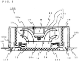
- Figs. 1 and 2 illustrate an indoor unit of an air-conditioning apparatus according to Embodiment 1 of the present invention.
- Fig. 1 is a schematic vertical sectional view.
- Fig. 2 is a schematic horizontal sectional view.
- the present Embodiment relates to an exemplary case of a ceiling-concealed air-conditioning apparatus
- the present invention is not limited thereto and may be widely applicable to indoor units of air-conditioning apparatuses including turbofans provided with pressure loss members that allow air to flow therethrough, such as filters and heat exchangers, at the air inlet side and the air outlet side of the fans.
- an indoor unit of an air-conditioning apparatus (hereinafter simply referred to as "indoor unit” also) 100 is housed in a recess provided in a ceiling 18 of a room 17.
- a body 10 is a casing including a rectangular top board 10a and a side board 10b standing from the circumference of the top board 10a.
- a side of the body 10 opposite the top board 10a is open, with a decorative panel 11 provided over the side having the opening.
- the indoor unit 100 is provided in the ceiling 18 in such an orientation that the top board 10a resides on the upper side and the decorative panel 11 resides on the lower side.
- the lower surface of the decorative panel 11 faces (is exposed in) the room 17 while slightly projecting from the lower surface (a surface facing the room 17) of the ceiling 18.
- the decorative panel 11 has near the center thereof an air inlet grille 11a through which air is taken into the body 10, a filter 12 that catches dust included in the air having passed through the air inlet grille 11a, and panel fan-air outlets 11b provided along respective sides of the decorative panel 11.
- the panel fan-air outlets 11b are provided with respective air-directing vanes 13 that change the direction of the air that is blown out.
- a fan motor 15 is provided on the top board 10a.
- a turbofan 1 is fixed to the rotating shaft of the fan motor 15.
- a bellmouth 14 that defines an intake air path extending from the air inlet grille 11a to the turbofan 1 is interposed between the filter 12 and the turbofan 1.
- a heat exchanger 16 having a substantially quadrilateral shape in plan view is provided around the outer circumference of the turbofan 1.
- the heat exchanger 16 is connected to an outdoor unit with a non-illustrated connection pipe.
- the turbofan 1 when the turbofan 1 is rotated, air in the room 17 is taken in through the air inlet grille 11a provided in the decorative panel 11 and passes through the filter 12, where dust is caught, into the bellmouth 14 provided in a body intake-air path 10c. After passing through the bellmouth 14, the air is taken into the turbofan 1 substantially upward (substantially parallel to the rotating shaft of the fan motor 15).
- the air is blown from the turbofan 1 toward the heat exchanger 16 in a substantially horizontal direction (a direction substantially perpendicular to the rotating shaft of the fan motor 15).
- the air that has been subjected to heat exchange for heating or cooling or has been dehumidified in the heat exchanger 16 i.e., the conditioned air
- the turbofan 1 will be described in detail in Embodiment 2.
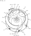
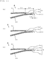
- Figs. 3 to 11 illustrate a turbofan according to Embodiment 2 of the present invention.
- Fig. 3 is a schematic perspective view.
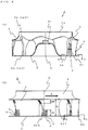
- Fig. 4 includes a schematic vertical sectional view and a schematic side view.
- Fig. 5 is an enlarged side view of a part (a blade front-edge portion).
- Fig. 6 is an enlarged horizontal sectional view of a part (a blade).
- Fig. 7 is an enlarged side view of a part (a blade rear-edge portion).
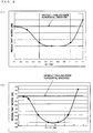
- Figs. 8 and 9 are performance charts each illustrating the relationship between the shape of a part (rear-edge horizontal grooves) and the resultant noise.
- Fig. 10 is a schematic side view illustrating a modification of a part (the rear-edge horizontal grooves).
- Fig. 11 includes schematic vertical sectional views illustrating other modifications of the part (the rear-edge horizontal grooves).
- Figs. 3 to 7 and 10 illustrate the turbofan in such an orientation that air is taken in from the upper side of the page toward the lower side thereof and is blown out in a substantially horizontal direction against the page; that is, the turbofan is oriented upside down compared with the orientation of the turbofan 1, illustrated in Fig. 1 (Embodiment 1), installed in the indoor unit 100.
- the turbofan 1 includes a substantially disc-shaped main plate 2 having a central portion thereof projecting in a mound shape, a substantially ring-shaped shroud 3 facing the main plate 2, and a plurality of blades 4 joined to the main plate 2 and the shroud 3.
- the shroud 3 has a substantially trumpet shape (a ring-shaped body having a substantially arc shape in sectional view).
- the center opening of the shroud 3 serves as a fan air inlet 1a.
- the shroud 3 provides an intake-air guide wall.
- the main plate 2 is integrally provided with a boss 2a at the top of the central projecting portion thereof.
- the boss 2a serves as a fixing portion to which the rotating shaft of the fan motor 15 is fixed.
- the center of the rotating shaft is referred to as "center of rotation O"
- the blades 4 each have a tapered shape in which a thickness T thereof (the distance between a blade outer-circumferential surface (blade positive-pressure surface) and a blade inner-circumferential surface (blade negative-pressure surface) in a horizontal section taken in a direction orthogonal to the rotating shaft) decreases in the height direction from the main plate 2 toward the shroud 3.
- Each blade 4 has a hollow structure with a cavity provided therein. The cavity communicates with an opening provided in the main plate 2 and is open at the lower surface of the main plate 2 (to the outside of an impeller).
- An area enclosed by each pair of adjacent blades 4, the shroud 3, and the main plate 2 serves as an airflow path.
- the outer circumferential end of the airflow path serves as a fan air outlet 1b.
- a blade front-edge portion 4a of the blade 4 is configured as follows.
- a portion of the blade outer-circumferential surface (corresponding to the blade positive-pressure surface) 4c nearer to the main plate 2 stands substantially vertical to the main plate 2.
- a portion of the blade outer-circumferential surface 4c nearer to the shroud 3 is gradually angled away from the center of rotation O while extending toward the shroud 3 (the portion is curved outward in the radial direction while extending upward).
- the blade inner-circumferential surface (corresponding to the blade negative-pressure surface) 4d is generally curved (bent) outward in the radial direction over the entirety thereof in the height direction from the main plate 2 to the shroud 3, the curve being more significant than that of the blade outer-circumferential surface 4c.
- blade front-edge end 4a1 a region of the blade front-edge portion 4a on the side of the blade inner-circumferential surface (corresponding to the blade negative-pressure surface) 4d is referred to as "blade front-edge end 4a1", and a line extending in the height direction in such a manner as to trace the center of thickness of the blade front-edge end 4a1 is referred to as "vertical camber line Q1".
- angle of bend ⁇ 1 at the blade front-edge end 4a1 In a plane containing the vertical camber line Q1, the angle formed between the vertical camber line Q1 and the center of rotation O (corresponding to a virtual line O' defined in the foregoing plane and being parallel to the center of rotation O) is referred to as "angle of bend ⁇ 1 at the blade front-edge end 4a1".
- blade shroud-side joint 4g The joint between the blade 4 and the shroud 3 on the inner circumferential side (a point from which the blade 4 starts to be spaced apart from the shroud 3) is referred to as "blade shroud-side joint 4g".
- a line extending in the height direction in such a manner as to trace the center of thickness is referred to as "vertical camber line Q2 (not illustrated)".
- angle of bend ⁇ 2 at the blade shroud-side joint 4g is referred to as "angle of bend ⁇ 2 at the blade shroud-side joint 4g".
- the "angle of bend ⁇ 2 at the blade shroud-side joint 4g" is smaller than the "angle of bend ⁇ 1 at the blade front-edge end 4a1". Furthermore, the angles of bend ⁇ gradually increase toward the center of the impeller (the center of rotation O). Furthermore, a blade shroud-side front edge portion 4a2 bends toward the outer side of the turbofan 1 (in a direction away from the center of rotation O) while extending toward the center.
- the blade front-edge end 4a1 (an end where the blade outer-circumferential surface (blade positive-pressure surface) 4c and the blade inner-circumferential surface (blade negative-pressure surface) 4d meet each other) bends toward the outer side of the impeller (in the direction away from the center of rotation O) while extending from the main plate 2 toward the shroud 3. Therefore, the induction of air to be taken in is promoted, whereby the occurrence of flow separation due to impact at the air inlet is suppressed.
- the airflow produced in the vertical direction (substantially parallel to the center of rotation O) in the body intake-air path 10c can be smoothly redirected radially toward the fan air-outlet 1b in a substantially horizontal direction (substantially perpendicularly to the center of rotation O) without being separated. Consequently, the turbofan 1 generates less noise. Hence, the indoor unit 100 including the turbofan 1 operates quietly and provides improved comfort.
- a line extending in such a manner as to trace the center of thickness is referred to as "horizontal camber line P1".
- the intersection of the horizontal camber line P1 and the blade front-edge end 4a1 is referred to as "main-plate-side end point 4a11 of the blade-inner-circumferential-side front-edge portion".
- main-plate-side end point 4b11 of the blade rear-edge portion The intersection of the horizontal camber line P1 and the blade rear-edge portion 4b is referred to as "main-plate-side end point 4b11 of the blade rear-edge portion".
- a line connecting the main-plate-side end point 4a11 of the blade-inner-circumferential-side front-edge portion and the main-plate-side end point 4b11 of the blade rear-edge portion is referred to as "main-plate-side blade chord 4e1" (see Fig. 6 ).
- the blade outer-circumferential surface 4c of the blade 4 has a plurality of rear-edge horizontal grooves 5 extending in the horizontal direction (in a plane perpendicular to the center of rotation O) and having a predetermined length L2 reaching the blade rear-edge portion 4b.
- the rear-edge horizontal grooves 5 wrap around groove wrapping portions 5b, which is provided at the terminal end of the blade rear-edge portion 4b, to the blade inner-circumferential surface 4d.
- the rear-edge horizontal grooves 5 are each a combination of a groove portion (a recessed portion, hereinafter referred to as "groove recessed portion") 5a provided with a predetermined depth in the blade outer-circumferential surface 4c and the groove wrapping portion 5b. Accordingly, the bottom of the groove recessed portion 5a resides near the blade inner-circumferential surface 4d. Therefore, the thickness of the blade 4 at the groove recessed portion 5a is small (see Fig. 6 ).
- main-plate-side blade chord L the length of the main-plate-side blade chord 4e1
- L2 the length of the rear-edge horizontal groove 5
- L3 the distance on the blade outer-circumferential surface 4c from the main-plate-side end point 4a11 of the blade-inner-circumferential-side front-edge portion to a point from which the rear-edge horizontal groove 5 starts to extend
- Fig. 6 illustrates one of the rear-edge horizontal grooves 5 that is nearest to the main plate 2 in the height direction. There are other plurality of rear-edge horizontal grooves 5 provided at positions farther from the main plate 2 in the height direction and extending parallel to one another (see Figs. 4 and 7 ).
- the rear-edge horizontal grooves 5 are provided in a region of the blade rear-edge portion 4b extending upward from the main plate 2 to a position defined by a distance H1 and in a region of the blade rear-edge portion 4b extending downward from the shroud 3 to a position defined by a distance H2.
- the distance H2 defining the region nearer to the shroud 3 where the rear-edge horizontal grooves 5 are provided is set to half the fan air-outlet height H or smaller (0 to 50%), the following effects are produced.
- the height of the rear-edge horizontal groove 5 (corresponding to the width of the groove recessed portion 5a in the height direction) is referred to as groove width D1
- the width, in the height direction, of an inter-groove surface portion 6 extending between adjacent ones of the groove recessed portions 5a is referred to as groove interval D2.
- blade front-edge end 4a1 an edge nearer to the center of rotation O where the blade outer-circumferential surface 4c and the blade inner-circumferential surface 4d meet is referred to as "blade front-edge end 4a1”
- blade rear-edge end 4b1 an edge farther from the center of rotation O
- blade chord 4e a line connecting the two is referred to as "blade chord 4e”.
- L the length of the blade chord 4e is also denoted by "L” (actually, the length of the blade chord 4e is not necessarily uniform and may vary with the position in the height direction).
- the plurality of rear-edge horizontal grooves 5 provided in the blade rear-edge portion 4b of the turbofan 1 each include the groove recessed portion 5a provided in the blade outer-circumferential surface (blade positive-pressure surface) 4c and extending in the horizontal direction and the groove wrapping portion 5b connecting the blade outer-circumferential surface (blade positive-pressure surface) 4c and the blade inner-circumferential surface (blade negative-pressure surface) 4d to each other at the end point of the blade rear-edge portion 4b.
- the airflow along the blade outer-circumferential surface 4c is induced into the groove recessed portion 5a provided on the side of the blade outer-circumferential surface 4c nearer to the blade rear-edge portion 4b, whereby the occurrence of separation of airflow is suppressed.
- the airflow may not be redirected sufficiently and may be separated slightly on a side of the fan air outlet 1b nearer to the shroud 3. Even in such a case, the rear-edge horizontal grooves 5 straighten the airflow. Thus, the occurrence of flow separation is suppressed, and the noise is reduced.
- the "main-plate-side end point 4b11 of the blade rear-edge portion" where the blade rear-edge portion 4b and the main plate 2 are joined to each other resides at, in a direction of rotation A, a position ahead of a "shroud-side end point 4b12 of the blade rear-edge portion" where the blade rear-edge portion 4b and the shroud 3 are joined to each other.
- the turbofan 1 and the indoor unit 100 generate very low noise with less change in the noise level that may be caused by turbulence.
- the horizontal axis represents the ratio of the length L2 of the rear-edge horizontal groove 5 to the main-plate-side blade chord L (L2/L), and the vertical axis represents the ratio of the noise generated by the turbofan 1 having the rear-edge horizontal grooves 5 to the noise generated by a turbofan having no rear-edge horizontal grooves 5 (hereinafter referred to as "resultant noise").
- the groove recessed portion 5a is also short. Therefore, the degree of the above-described effects (straightening of airflow and prevention of flow separation) is low.
- the length L2 of the rear-edge horizontal groove 5 is preferably set to 10% to 50% of the blade chord length L (0.1 xL ⁇ L2 ⁇ 0.5xL).
- the turbofan 1 and the indoor unit 100 generate much less noise without reduction in the air-sending efficiency.
- the horizontal axis represents the ratio of groove width D1 of the rear-edge horizontal groove 5 to the groove interval D2 (D1/D2), and the vertical axis represents the resultant noise.
- the groove width D1 and the groove interval D2 preferably satisfy at least a relationship of "0.5xD2 ⁇ D1 ⁇ 1.0 ⁇ D2".
- the turbofan 1 and the indoor unit 100 generate less noise.
- the horizontal axis represents the ratio of the groove width D1 to the fan height H (D1/H), and the vertical axis represents the resultant noise.
- the ratio (D1/H) is too small, the resultant noise increases (the resultant noise becomes a large positive value) because air does not flow into the rear-edge horizontal groove 5.
- the ratio (D1/H) is too large, noise is generated because an excessive amount of air flows into the rear-edge horizontal groove 5 and the effect of straightening the airflow is eliminated.
- the ratio (D1/H) is preferably set to "2 to 5%".
- the inter-groove surface portions 6 each include an inter-groove continuous surface 6a that is continuous with the blade outer-circumferential surface 4c, and an inter-groove projection 6b that is provided in a predetermined region near the end of the blade rear-edge portion 4b and that projects toward the outer circumferential side.
- One of the inter-groove projections 6b of the inter-groove surface portions 6 that is provided at a certain height has a length L4 that is different from lengths L4 of other inter-groove projections 6b of the inter-groove surface portions 6 that are adjacent thereto in the vertical direction. That is, the inter-groove projections 6b extend from staggered positions in side view.
- the airflow is diffused because the speed of airflow in the rear-edge horizontal grooves 5 is different from that on the inter-groove projections 6b.
- the speed of airflow is also different between adjacent ones of the inter-groove projections 6b. Therefore, the airflow is diffused.
- shed vortices at the rear edge interact with one another and cancel one another out. Thus, a further noise reduction is realized.
- the thickness at the groove recessed portion 5a of each rear-edge horizontal groove 5 is substantially the same as the thickness of a central portion (having a cavity) of the blade 4. Therefore, the depth (degree of recess) of the groove recessed portion 5a becomes smaller (decreases) toward the blade rear-edge portion 4b.
- the depth (degree of recess) of the groove recessed portion 5a of the rear-edge horizontal groove 5 is substantially uniform. Therefore, the thickness at the groove recessed portion 5a becomes smaller (decreases) toward the blade rear-edge portion 4b.
- the blade inner-circumferential surface 4d has a groove-type recess (hereinafter referred to as "negative-pressure-side groove recessed portion”) 5c that reaches the groove wrapping portion 5b. Therefore, in combination with the groove recessed portion 5a provided in the blade inner-circumferential surface 4d, the above-described operational effects are promoted.
- the present invention is widely applicable to turbofans of different types and to indoor units of air-conditioning apparatuses for different types (not limited to the ceiling-concealed type) including the turbofans.
- 1 turbofan 1a fan air inlet, 1b fan air outlet, 2 main plate, 2a boss, 3 shroud, 4 blade, 4a blade front-edge portion, 4a1 blade front-edge end, 4a11 main-plate-side end point, 4a2 blade shroud-side front edge portion, 4b blade rear-edge portion, 4b1 blade rear-edge end, 4b11 main-plate-side end point, 4b12 shroud-side end point, 4c blade outer-circumferential surface, 4d blade inner-circumferential surface, 4e blade chord, 4e1 main-plate-side blade chord, 4g blade shroud-side joint, 5 rear-edge horizontal groove, 5a groove recessed portion, 5b groove wrapping portion, 5c negative-pressure-side groove recessed portion, 6 inter-groove surface portion, 6a inter-groove continuous surface, 6b inter-groove projection, 10 body, 10a top board, 10b side board, 10c body intake-air path, 10d body outflow-air path, 11 decorative panel,
Landscapes
- Engineering & Computer Science (AREA)
- Mechanical Engineering (AREA)
- General Engineering & Computer Science (AREA)
- Structures Of Non-Positive Displacement Pumps (AREA)
Applications Claiming Priority (2)
| Application Number | Priority Date | Filing Date | Title |
|---|---|---|---|
| JP2010074052A JP5143173B2 (ja) | 2010-03-29 | 2010-03-29 | ターボファン及びこれを装備した空気調和機の室内機 |
| PCT/JP2011/001718 WO2011121943A1 (ja) | 2010-03-29 | 2011-03-24 | ターボファン及びこれを装備した空気調和機の室内機 |
Publications (3)
| Publication Number | Publication Date |
|---|---|
| EP2554850A1 EP2554850A1 (en) | 2013-02-06 |
| EP2554850A4 EP2554850A4 (en) | 2016-05-11 |
| EP2554850B1 true EP2554850B1 (en) | 2019-08-28 |
Family
ID=44711710
Family Applications (1)
| Application Number | Title | Priority Date | Filing Date |
|---|---|---|---|
| EP11762195.3A Active EP2554850B1 (en) | 2010-03-29 | 2011-03-24 | Turbofan and indoor air conditioner equipped with same |
Country Status (6)
| Country | Link |
|---|---|
| US (1) | US9267511B2 (ja) |
| EP (1) | EP2554850B1 (ja) |
| JP (1) | JP5143173B2 (ja) |
| CN (1) | CN102822532B (ja) |
| ES (1) | ES2747983T3 (ja) |
| WO (1) | WO2011121943A1 (ja) |
Cited By (1)
| Publication number | Priority date | Publication date | Assignee | Title |
|---|---|---|---|---|
| DE102019121448A1 (de) * | 2019-08-08 | 2021-02-11 | Ebm-Papst Mulfingen Gmbh & Co. Kg | Radialgebläse für einen Dunstabzug |
Families Citing this family (17)
| Publication number | Priority date | Publication date | Assignee | Title |
|---|---|---|---|---|
| JP6078945B2 (ja) * | 2011-11-04 | 2017-02-15 | ダイキン工業株式会社 | 遠心送風機 |
| KR20140125522A (ko) * | 2013-04-19 | 2014-10-29 | 엘지전자 주식회사 | 터보팬 |
| KR101645178B1 (ko) * | 2013-05-10 | 2016-08-03 | 엘지전자 주식회사 | 원심팬 및 원심팬의 제조방법 |
| US9995311B2 (en) | 2013-05-10 | 2018-06-12 | Lg Electronics Inc. | Centrifugal fan |
| CN104251231A (zh) * | 2013-06-28 | 2014-12-31 | 苏州宝时得电动工具有限公司 | 离心式叶轮及包括该离心式叶轮的吹吸装置 |
| CN105793578B (zh) * | 2013-12-04 | 2018-10-16 | 松下知识产权经营株式会社 | 风机和装载有该风机的室外单元 |
| JP6218160B2 (ja) * | 2014-10-30 | 2017-10-25 | 三菱電機株式会社 | ターボファンおよび空気調和装置用室内機 |
| JP5839755B1 (ja) * | 2015-01-08 | 2016-01-06 | 山洋電気株式会社 | ファンケーシング及びファン装置 |
| CN104763652A (zh) * | 2015-02-04 | 2015-07-08 | 张宏松 | 一种卧式鼓风机 |
| US10648681B2 (en) * | 2016-07-19 | 2020-05-12 | Mitsubishi Electric Corporation | Heat source unit and refrigeration cycle apparatus |
| JP6690730B2 (ja) * | 2016-11-01 | 2020-04-28 | 株式会社Ihi | 可変ノズルユニットおよび過給機 |
| JP6762426B2 (ja) * | 2017-05-22 | 2020-09-30 | 三菱電機株式会社 | 空気調和機 |
| ES2892967T3 (es) * | 2017-07-26 | 2022-02-07 | Mitsubishi Electric Corp | Acondicionador de aire |
| JP7207933B2 (ja) * | 2018-10-15 | 2023-01-18 | 日立建機株式会社 | 建設機械 |
| EP3647603A1 (en) | 2018-10-31 | 2020-05-06 | Carrier Corporation | Arrangement of centrifugal impeller of a fan for reducing noise |
| CN111043079A (zh) * | 2019-12-31 | 2020-04-21 | 潍柴动力股份有限公司 | 一种风扇叶片及风扇 |
| TWI724872B (zh) * | 2020-04-17 | 2021-04-11 | 建準電機工業股份有限公司 | 離心扇輪及具有該離心扇輪的離心風扇 |
Citations (1)
| Publication number | Priority date | Publication date | Assignee | Title |
|---|---|---|---|---|
| EP2003340A2 (en) * | 2006-03-31 | 2008-12-17 | Daikin Industries, Ltd. | Multi-blade fan |
Family Cites Families (8)
| Publication number | Priority date | Publication date | Assignee | Title |
|---|---|---|---|---|
| GB8829792D0 (en) * | 1988-12-21 | 1989-07-05 | Marconi Co Ltd | Noise reduction method |
| JP2669448B2 (ja) | 1993-06-15 | 1997-10-27 | 松下冷機株式会社 | 遠心送風機の羽根車 |
| JPH09126190A (ja) | 1995-10-30 | 1997-05-13 | Sanyo Electric Co Ltd | 遠心式送風機 |
| JP3092554B2 (ja) | 1997-09-30 | 2000-09-25 | ダイキン工業株式会社 | 遠心送風機及びその製造方法並びに該遠心送風機を備えた空気調和機 |
| KR20040104772A (ko) * | 2003-06-03 | 2004-12-13 | 삼성전자주식회사 | 터보팬 및 이를 갖춘 공기조화기 |
| JP2006002691A (ja) * | 2004-06-18 | 2006-01-05 | Calsonic Kansei Corp | 送風機 |
| JP2007247492A (ja) * | 2006-03-15 | 2007-09-27 | Matsushita Electric Ind Co Ltd | 電動送風機およびそれを用いた電気掃除機 |
| KR20080045568A (ko) * | 2006-11-20 | 2008-05-23 | 삼성전자주식회사 | 터보팬 및 이를 갖춘 공기조화기 |
-
2010
- 2010-03-29 JP JP2010074052A patent/JP5143173B2/ja active Active
-
2011
- 2011-03-24 US US13/582,933 patent/US9267511B2/en active Active
- 2011-03-24 WO PCT/JP2011/001718 patent/WO2011121943A1/ja active Application Filing
- 2011-03-24 CN CN201180016013.2A patent/CN102822532B/zh active Active
- 2011-03-24 ES ES11762195T patent/ES2747983T3/es active Active
- 2011-03-24 EP EP11762195.3A patent/EP2554850B1/en active Active
Patent Citations (1)
| Publication number | Priority date | Publication date | Assignee | Title |
|---|---|---|---|---|
| EP2003340A2 (en) * | 2006-03-31 | 2008-12-17 | Daikin Industries, Ltd. | Multi-blade fan |
Cited By (1)
| Publication number | Priority date | Publication date | Assignee | Title |
|---|---|---|---|---|
| DE102019121448A1 (de) * | 2019-08-08 | 2021-02-11 | Ebm-Papst Mulfingen Gmbh & Co. Kg | Radialgebläse für einen Dunstabzug |
Also Published As
| Publication number | Publication date |
|---|---|
| US20120328420A1 (en) | 2012-12-27 |
| JP2011208501A (ja) | 2011-10-20 |
| CN102822532A (zh) | 2012-12-12 |
| WO2011121943A1 (ja) | 2011-10-06 |
| EP2554850A4 (en) | 2016-05-11 |
| US9267511B2 (en) | 2016-02-23 |
| CN102822532B (zh) | 2016-02-17 |
| JP5143173B2 (ja) | 2013-02-13 |
| ES2747983T3 (es) | 2020-03-12 |
| EP2554850A1 (en) | 2013-02-06 |
Similar Documents
| Publication | Publication Date | Title |
|---|---|---|
| EP2554850B1 (en) | Turbofan and indoor air conditioner equipped with same | |
| US9885364B2 (en) | Fan, molding die, and fluid feeder | |
| US9829004B2 (en) | Turbo fan and air conditioner | |
| WO2009139422A1 (ja) | 遠心送風機 | |
| JP5178816B2 (ja) | 空気調和機 | |
| JP3268279B2 (ja) | 空気調和機 | |
| EP2719957A1 (en) | Air conditioner | |
| WO2010053037A1 (ja) | 送風機及びこの送風機を用いたヒートポンプ装置 | |
| JP6304441B1 (ja) | クロスフロー型の送風機及びそれを備えた空気調和装置の室内ユニット | |
| US9759220B2 (en) | Cross flow fan and indoor unit of air-conditioning apparatus | |
| JP5744209B2 (ja) | 空気調和機 | |
| JP6078945B2 (ja) | 遠心送風機 | |
| US10690142B2 (en) | Blade of cross-flow fan | |
| EP2280176B1 (en) | Cross flow fan and air conditioner equipped with same | |
| JP2014031994A (ja) | 空気調和機 | |
| JP4775867B1 (ja) | ファン、成型用金型および流体送り装置 | |
| CN108375125B (zh) | 窗式空调设备 | |
| JP2016003641A (ja) | 遠心ファン | |
| JP2002357194A (ja) | 貫流ファン | |
| JP6642913B2 (ja) | ターボファンおよびそれを用いた空気調和機 | |
| JP4214994B2 (ja) | 空気調和機 | |
| JP6852768B1 (ja) | クロスフローファンの翼、クロスフローファン及び空調室内機 | |
| JP2000146214A (ja) | 空気調和機 | |
| CN118009424A (zh) | 风道组件、室内机以及暖通系统 | |
| CN116997725A (zh) | 涡壳、具备该涡壳的送风装置以及空调装置 |
Legal Events
| Date | Code | Title | Description |
|---|---|---|---|
| PUAI | Public reference made under article 153(3) epc to a published international application that has entered the european phase |
Free format text: ORIGINAL CODE: 0009012 |
|
| 17P | Request for examination filed |
Effective date: 20120831 |
|
| AK | Designated contracting states |
Kind code of ref document: A1 Designated state(s): AL AT BE BG CH CY CZ DE DK EE ES FI FR GB GR HR HU IE IS IT LI LT LU LV MC MK MT NL NO PL PT RO RS SE SI SK SM TR |
|
| DAX | Request for extension of the european patent (deleted) | ||
| RA4 | Supplementary search report drawn up and despatched (corrected) |
Effective date: 20160412 |
|
| RIC1 | Information provided on ipc code assigned before grant |
Ipc: F04D 29/28 20060101ALI20160406BHEP Ipc: F04D 29/30 20060101AFI20160406BHEP |
|
| GRAP | Despatch of communication of intention to grant a patent |
Free format text: ORIGINAL CODE: EPIDOSNIGR1 |
|
| STAA | Information on the status of an ep patent application or granted ep patent |
Free format text: STATUS: GRANT OF PATENT IS INTENDED |
|
| INTG | Intention to grant announced |
Effective date: 20190412 |
|
| GRAS | Grant fee paid |
Free format text: ORIGINAL CODE: EPIDOSNIGR3 |
|
| GRAA | (expected) grant |
Free format text: ORIGINAL CODE: 0009210 |
|
| STAA | Information on the status of an ep patent application or granted ep patent |
Free format text: STATUS: THE PATENT HAS BEEN GRANTED |
|
| AK | Designated contracting states |
Kind code of ref document: B1 Designated state(s): AL AT BE BG CH CY CZ DE DK EE ES FI FR GB GR HR HU IE IS IT LI LT LU LV MC MK MT NL NO PL PT RO RS SE SI SK SM TR |
|
| REG | Reference to a national code |
Ref country code: GB Ref legal event code: FG4D |
|
| REG | Reference to a national code |
Ref country code: CH Ref legal event code: EP |
|
| REG | Reference to a national code |
Ref country code: AT Ref legal event code: REF Ref document number: 1172751 Country of ref document: AT Kind code of ref document: T Effective date: 20190915 |
|
| REG | Reference to a national code |
Ref country code: IE Ref legal event code: FG4D |
|
| REG | Reference to a national code |
Ref country code: DE Ref legal event code: R096 Ref document number: 602011061626 Country of ref document: DE |
|
| REG | Reference to a national code |
Ref country code: NL Ref legal event code: MP Effective date: 20190828 |
|
| REG | Reference to a national code |
Ref country code: LT Ref legal event code: MG4D |
|
| PG25 | Lapsed in a contracting state [announced via postgrant information from national office to epo] |
Ref country code: BG Free format text: LAPSE BECAUSE OF FAILURE TO SUBMIT A TRANSLATION OF THE DESCRIPTION OR TO PAY THE FEE WITHIN THE PRESCRIBED TIME-LIMIT Effective date: 20191128 Ref country code: NL Free format text: LAPSE BECAUSE OF FAILURE TO SUBMIT A TRANSLATION OF THE DESCRIPTION OR TO PAY THE FEE WITHIN THE PRESCRIBED TIME-LIMIT Effective date: 20190828 Ref country code: LT Free format text: LAPSE BECAUSE OF FAILURE TO SUBMIT A TRANSLATION OF THE DESCRIPTION OR TO PAY THE FEE WITHIN THE PRESCRIBED TIME-LIMIT Effective date: 20190828 Ref country code: HR Free format text: LAPSE BECAUSE OF FAILURE TO SUBMIT A TRANSLATION OF THE DESCRIPTION OR TO PAY THE FEE WITHIN THE PRESCRIBED TIME-LIMIT Effective date: 20190828 Ref country code: PT Free format text: LAPSE BECAUSE OF FAILURE TO SUBMIT A TRANSLATION OF THE DESCRIPTION OR TO PAY THE FEE WITHIN THE PRESCRIBED TIME-LIMIT Effective date: 20191230 Ref country code: NO Free format text: LAPSE BECAUSE OF FAILURE TO SUBMIT A TRANSLATION OF THE DESCRIPTION OR TO PAY THE FEE WITHIN THE PRESCRIBED TIME-LIMIT Effective date: 20191128 Ref country code: SE Free format text: LAPSE BECAUSE OF FAILURE TO SUBMIT A TRANSLATION OF THE DESCRIPTION OR TO PAY THE FEE WITHIN THE PRESCRIBED TIME-LIMIT Effective date: 20190828 Ref country code: FI Free format text: LAPSE BECAUSE OF FAILURE TO SUBMIT A TRANSLATION OF THE DESCRIPTION OR TO PAY THE FEE WITHIN THE PRESCRIBED TIME-LIMIT Effective date: 20190828 |
|
| PG25 | Lapsed in a contracting state [announced via postgrant information from national office to epo] |
Ref country code: IS Free format text: LAPSE BECAUSE OF FAILURE TO SUBMIT A TRANSLATION OF THE DESCRIPTION OR TO PAY THE FEE WITHIN THE PRESCRIBED TIME-LIMIT Effective date: 20191228 Ref country code: RS Free format text: LAPSE BECAUSE OF FAILURE TO SUBMIT A TRANSLATION OF THE DESCRIPTION OR TO PAY THE FEE WITHIN THE PRESCRIBED TIME-LIMIT Effective date: 20190828 Ref country code: GR Free format text: LAPSE BECAUSE OF FAILURE TO SUBMIT A TRANSLATION OF THE DESCRIPTION OR TO PAY THE FEE WITHIN THE PRESCRIBED TIME-LIMIT Effective date: 20191129 Ref country code: AL Free format text: LAPSE BECAUSE OF FAILURE TO SUBMIT A TRANSLATION OF THE DESCRIPTION OR TO PAY THE FEE WITHIN THE PRESCRIBED TIME-LIMIT Effective date: 20190828 Ref country code: LV Free format text: LAPSE BECAUSE OF FAILURE TO SUBMIT A TRANSLATION OF THE DESCRIPTION OR TO PAY THE FEE WITHIN THE PRESCRIBED TIME-LIMIT Effective date: 20190828 |
|
| REG | Reference to a national code |
Ref country code: ES Ref legal event code: FG2A Ref document number: 2747983 Country of ref document: ES Kind code of ref document: T3 Effective date: 20200312 |
|
| REG | Reference to a national code |
Ref country code: AT Ref legal event code: MK05 Ref document number: 1172751 Country of ref document: AT Kind code of ref document: T Effective date: 20190828 |
|
| PG25 | Lapsed in a contracting state [announced via postgrant information from national office to epo] |
Ref country code: TR Free format text: LAPSE BECAUSE OF FAILURE TO SUBMIT A TRANSLATION OF THE DESCRIPTION OR TO PAY THE FEE WITHIN THE PRESCRIBED TIME-LIMIT Effective date: 20190828 |
|
| PG25 | Lapsed in a contracting state [announced via postgrant information from national office to epo] |
Ref country code: IT Free format text: LAPSE BECAUSE OF FAILURE TO SUBMIT A TRANSLATION OF THE DESCRIPTION OR TO PAY THE FEE WITHIN THE PRESCRIBED TIME-LIMIT Effective date: 20190828 Ref country code: RO Free format text: LAPSE BECAUSE OF FAILURE TO SUBMIT A TRANSLATION OF THE DESCRIPTION OR TO PAY THE FEE WITHIN THE PRESCRIBED TIME-LIMIT Effective date: 20190828 Ref country code: AT Free format text: LAPSE BECAUSE OF FAILURE TO SUBMIT A TRANSLATION OF THE DESCRIPTION OR TO PAY THE FEE WITHIN THE PRESCRIBED TIME-LIMIT Effective date: 20190828 Ref country code: EE Free format text: LAPSE BECAUSE OF FAILURE TO SUBMIT A TRANSLATION OF THE DESCRIPTION OR TO PAY THE FEE WITHIN THE PRESCRIBED TIME-LIMIT Effective date: 20190828 Ref country code: DK Free format text: LAPSE BECAUSE OF FAILURE TO SUBMIT A TRANSLATION OF THE DESCRIPTION OR TO PAY THE FEE WITHIN THE PRESCRIBED TIME-LIMIT Effective date: 20190828 Ref country code: PL Free format text: LAPSE BECAUSE OF FAILURE TO SUBMIT A TRANSLATION OF THE DESCRIPTION OR TO PAY THE FEE WITHIN THE PRESCRIBED TIME-LIMIT Effective date: 20190828 |
|
| PG25 | Lapsed in a contracting state [announced via postgrant information from national office to epo] |
Ref country code: CZ Free format text: LAPSE BECAUSE OF FAILURE TO SUBMIT A TRANSLATION OF THE DESCRIPTION OR TO PAY THE FEE WITHIN THE PRESCRIBED TIME-LIMIT Effective date: 20190828 Ref country code: SK Free format text: LAPSE BECAUSE OF FAILURE TO SUBMIT A TRANSLATION OF THE DESCRIPTION OR TO PAY THE FEE WITHIN THE PRESCRIBED TIME-LIMIT Effective date: 20190828 Ref country code: SM Free format text: LAPSE BECAUSE OF FAILURE TO SUBMIT A TRANSLATION OF THE DESCRIPTION OR TO PAY THE FEE WITHIN THE PRESCRIBED TIME-LIMIT Effective date: 20190828 Ref country code: IS Free format text: LAPSE BECAUSE OF FAILURE TO SUBMIT A TRANSLATION OF THE DESCRIPTION OR TO PAY THE FEE WITHIN THE PRESCRIBED TIME-LIMIT Effective date: 20200224 |
|
| REG | Reference to a national code |
Ref country code: DE Ref legal event code: R097 Ref document number: 602011061626 Country of ref document: DE |
|
| PLBE | No opposition filed within time limit |
Free format text: ORIGINAL CODE: 0009261 |
|
| STAA | Information on the status of an ep patent application or granted ep patent |
Free format text: STATUS: NO OPPOSITION FILED WITHIN TIME LIMIT |
|
| PG2D | Information on lapse in contracting state deleted |
Ref country code: IS |
|
| 26N | No opposition filed |
Effective date: 20200603 |
|
| PG25 | Lapsed in a contracting state [announced via postgrant information from national office to epo] |
Ref country code: SI Free format text: LAPSE BECAUSE OF FAILURE TO SUBMIT A TRANSLATION OF THE DESCRIPTION OR TO PAY THE FEE WITHIN THE PRESCRIBED TIME-LIMIT Effective date: 20190828 |
|
| PG25 | Lapsed in a contracting state [announced via postgrant information from national office to epo] |
Ref country code: MC Free format text: LAPSE BECAUSE OF FAILURE TO SUBMIT A TRANSLATION OF THE DESCRIPTION OR TO PAY THE FEE WITHIN THE PRESCRIBED TIME-LIMIT Effective date: 20190828 |
|
| REG | Reference to a national code |
Ref country code: CH Ref legal event code: PL |
|
| REG | Reference to a national code |
Ref country code: BE Ref legal event code: MM Effective date: 20200331 |
|
| PG25 | Lapsed in a contracting state [announced via postgrant information from national office to epo] |
Ref country code: LU Free format text: LAPSE BECAUSE OF NON-PAYMENT OF DUE FEES Effective date: 20200324 |
|
| PG25 | Lapsed in a contracting state [announced via postgrant information from national office to epo] |
Ref country code: LI Free format text: LAPSE BECAUSE OF NON-PAYMENT OF DUE FEES Effective date: 20200331 Ref country code: CH Free format text: LAPSE BECAUSE OF NON-PAYMENT OF DUE FEES Effective date: 20200331 Ref country code: FR Free format text: LAPSE BECAUSE OF NON-PAYMENT OF DUE FEES Effective date: 20200331 Ref country code: IE Free format text: LAPSE BECAUSE OF NON-PAYMENT OF DUE FEES Effective date: 20200324 |
|
| PG25 | Lapsed in a contracting state [announced via postgrant information from national office to epo] |
Ref country code: BE Free format text: LAPSE BECAUSE OF NON-PAYMENT OF DUE FEES Effective date: 20200331 |
|
| PG25 | Lapsed in a contracting state [announced via postgrant information from national office to epo] |
Ref country code: MT Free format text: LAPSE BECAUSE OF FAILURE TO SUBMIT A TRANSLATION OF THE DESCRIPTION OR TO PAY THE FEE WITHIN THE PRESCRIBED TIME-LIMIT Effective date: 20190828 Ref country code: CY Free format text: LAPSE BECAUSE OF FAILURE TO SUBMIT A TRANSLATION OF THE DESCRIPTION OR TO PAY THE FEE WITHIN THE PRESCRIBED TIME-LIMIT Effective date: 20190828 |
|
| PG25 | Lapsed in a contracting state [announced via postgrant information from national office to epo] |
Ref country code: MK Free format text: LAPSE BECAUSE OF FAILURE TO SUBMIT A TRANSLATION OF THE DESCRIPTION OR TO PAY THE FEE WITHIN THE PRESCRIBED TIME-LIMIT Effective date: 20190828 |
|
| P01 | Opt-out of the competence of the unified patent court (upc) registered |
Effective date: 20230512 |
|
| REG | Reference to a national code |
Ref country code: DE Ref legal event code: R084 Ref document number: 602011061626 Country of ref document: DE |
|
| PGFP | Annual fee paid to national office [announced via postgrant information from national office to epo] |
Ref country code: ES Payment date: 20230404 Year of fee payment: 13 |
|
| REG | Reference to a national code |
Ref country code: ES Ref legal event code: GC2A Effective date: 20240411 Ref country code: GB Ref legal event code: 746 Effective date: 20240325 |
|
| PGFP | Annual fee paid to national office [announced via postgrant information from national office to epo] |
Ref country code: DE Payment date: 20240130 Year of fee payment: 14 Ref country code: GB Payment date: 20240201 Year of fee payment: 14 |