EP2554491B1 - Gasadsorptionsvorrichtungsstruktur und verfahren für deren verwendung - Google Patents
Gasadsorptionsvorrichtungsstruktur und verfahren für deren verwendung Download PDFInfo
- Publication number
- EP2554491B1 EP2554491B1 EP11758954.9A EP11758954A EP2554491B1 EP 2554491 B1 EP2554491 B1 EP 2554491B1 EP 11758954 A EP11758954 A EP 11758954A EP 2554491 B1 EP2554491 B1 EP 2554491B1
- Authority
- EP
- European Patent Office
- Prior art keywords
- adsorption device
- gas
- gas adsorption
- outer package
- package
- Prior art date
- Legal status (The legal status is an assumption and is not a legal conclusion. Google has not performed a legal analysis and makes no representation as to the accuracy of the status listed.)
- Not-in-force
Links
- 238000001179 sorption measurement Methods 0.000 title claims description 206
- 238000000034 method Methods 0.000 title claims description 11
- 239000003463 adsorbent Substances 0.000 claims description 51
- 230000035699 permeability Effects 0.000 claims description 11
- 238000007789 sealing Methods 0.000 claims description 11
- 239000007789 gas Substances 0.000 description 213
- 230000000717 retained effect Effects 0.000 description 18
- XEEYBQQBJWHFJM-UHFFFAOYSA-N Iron Chemical compound [Fe] XEEYBQQBJWHFJM-UHFFFAOYSA-N 0.000 description 14
- 239000000463 material Substances 0.000 description 13
- 239000012212 insulator Substances 0.000 description 10
- 229920001684 low density polyethylene Polymers 0.000 description 8
- 239000004702 low-density polyethylene Substances 0.000 description 8
- 238000003860 storage Methods 0.000 description 8
- 229910052742 iron Inorganic materials 0.000 description 7
- 230000035882 stress Effects 0.000 description 6
- 229910052782 aluminium Inorganic materials 0.000 description 4
- XAGFODPZIPBFFR-UHFFFAOYSA-N aluminium Chemical compound [Al] XAGFODPZIPBFFR-UHFFFAOYSA-N 0.000 description 4
- 230000015556 catabolic process Effects 0.000 description 4
- 238000006731 degradation reaction Methods 0.000 description 4
- 229920006284 nylon film Polymers 0.000 description 4
- 238000003466 welding Methods 0.000 description 4
- WMFOQBRAJBCJND-UHFFFAOYSA-M Lithium hydroxide Chemical compound [Li+].[OH-] WMFOQBRAJBCJND-UHFFFAOYSA-M 0.000 description 3
- 238000010030 laminating Methods 0.000 description 3
- 238000004519 manufacturing process Methods 0.000 description 3
- -1 polyethylene Polymers 0.000 description 3
- IJGRMHOSHXDMSA-UHFFFAOYSA-N Atomic nitrogen Chemical compound N#N IJGRMHOSHXDMSA-UHFFFAOYSA-N 0.000 description 2
- 229910052783 alkali metal Inorganic materials 0.000 description 2
- 150000001340 alkali metals Chemical class 0.000 description 2
- 229910052784 alkaline earth metal Inorganic materials 0.000 description 2
- QVQLCTNNEUAWMS-UHFFFAOYSA-N barium oxide Chemical compound [Ba]=O QVQLCTNNEUAWMS-UHFFFAOYSA-N 0.000 description 2
- 150000004679 hydroxides Chemical class 0.000 description 2
- 230000002427 irreversible effect Effects 0.000 description 2
- 238000005259 measurement Methods 0.000 description 2
- 229910052751 metal Inorganic materials 0.000 description 2
- 239000002184 metal Substances 0.000 description 2
- 239000012466 permeate Substances 0.000 description 2
- 239000002985 plastic film Substances 0.000 description 2
- 229920006255 plastic film Polymers 0.000 description 2
- 239000000126 substance Substances 0.000 description 2
- 229920000219 Ethylene vinyl alcohol Polymers 0.000 description 1
- 239000004698 Polyethylene Substances 0.000 description 1
- 239000004743 Polypropylene Substances 0.000 description 1
- 239000004793 Polystyrene Substances 0.000 description 1
- 239000004372 Polyvinyl alcohol Substances 0.000 description 1
- 229910001854 alkali hydroxide Inorganic materials 0.000 description 1
- QVGXLLKOCUKJST-UHFFFAOYSA-N atomic oxygen Chemical compound [O] QVGXLLKOCUKJST-UHFFFAOYSA-N 0.000 description 1
- RQPZNWPYLFFXCP-UHFFFAOYSA-L barium dihydroxide Chemical compound [OH-].[OH-].[Ba+2] RQPZNWPYLFFXCP-UHFFFAOYSA-L 0.000 description 1
- 229910001863 barium hydroxide Inorganic materials 0.000 description 1
- 239000012141 concentrate Substances 0.000 description 1
- 238000005336 cracking Methods 0.000 description 1
- 230000002950 deficient Effects 0.000 description 1
- 230000006355 external stress Effects 0.000 description 1
- 239000006260 foam Substances 0.000 description 1
- 239000011521 glass Substances 0.000 description 1
- 238000007689 inspection Methods 0.000 description 1
- 238000009413 insulation Methods 0.000 description 1
- 239000005001 laminate film Substances 0.000 description 1
- FUJCRWPEOMXPAD-UHFFFAOYSA-N lithium oxide Chemical compound [Li+].[Li+].[O-2] FUJCRWPEOMXPAD-UHFFFAOYSA-N 0.000 description 1
- 229910001947 lithium oxide Inorganic materials 0.000 description 1
- 229910052757 nitrogen Inorganic materials 0.000 description 1
- 239000001301 oxygen Substances 0.000 description 1
- 229910052760 oxygen Inorganic materials 0.000 description 1
- 229920006289 polycarbonate film Polymers 0.000 description 1
- 229920000573 polyethylene Polymers 0.000 description 1
- 229920000139 polyethylene terephthalate Polymers 0.000 description 1
- 239000005020 polyethylene terephthalate Substances 0.000 description 1
- 229920001155 polypropylene Polymers 0.000 description 1
- 229920002223 polystyrene Polymers 0.000 description 1
- 229920002451 polyvinyl alcohol Polymers 0.000 description 1
- 239000000047 product Substances 0.000 description 1
Images


Classifications
-
- B—PERFORMING OPERATIONS; TRANSPORTING
- B01—PHYSICAL OR CHEMICAL PROCESSES OR APPARATUS IN GENERAL
- B01D—SEPARATION
- B01D53/00—Separation of gases or vapours; Recovering vapours of volatile solvents from gases; Chemical or biological purification of waste gases, e.g. engine exhaust gases, smoke, fumes, flue gases, aerosols
- B01D53/02—Separation of gases or vapours; Recovering vapours of volatile solvents from gases; Chemical or biological purification of waste gases, e.g. engine exhaust gases, smoke, fumes, flue gases, aerosols by adsorption, e.g. preparative gas chromatography
- B01D53/04—Separation of gases or vapours; Recovering vapours of volatile solvents from gases; Chemical or biological purification of waste gases, e.g. engine exhaust gases, smoke, fumes, flue gases, aerosols by adsorption, e.g. preparative gas chromatography with stationary adsorbents
- B01D53/0407—Constructional details of adsorbing systems
-
- B—PERFORMING OPERATIONS; TRANSPORTING
- B01—PHYSICAL OR CHEMICAL PROCESSES OR APPARATUS IN GENERAL
- B01J—CHEMICAL OR PHYSICAL PROCESSES, e.g. CATALYSIS OR COLLOID CHEMISTRY; THEIR RELEVANT APPARATUS
- B01J20/00—Solid sorbent compositions or filter aid compositions; Sorbents for chromatography; Processes for preparing, regenerating or reactivating thereof
- B01J20/02—Solid sorbent compositions or filter aid compositions; Sorbents for chromatography; Processes for preparing, regenerating or reactivating thereof comprising inorganic material
- B01J20/10—Solid sorbent compositions or filter aid compositions; Sorbents for chromatography; Processes for preparing, regenerating or reactivating thereof comprising inorganic material comprising silica or silicate
- B01J20/16—Alumino-silicates
- B01J20/18—Synthetic zeolitic molecular sieves
- B01J20/186—Chemical treatments in view of modifying the properties of the sieve, e.g. increasing the stability or the activity, also decreasing the activity
-
- B—PERFORMING OPERATIONS; TRANSPORTING
- B01—PHYSICAL OR CHEMICAL PROCESSES OR APPARATUS IN GENERAL
- B01J—CHEMICAL OR PHYSICAL PROCESSES, e.g. CATALYSIS OR COLLOID CHEMISTRY; THEIR RELEVANT APPARATUS
- B01J20/00—Solid sorbent compositions or filter aid compositions; Sorbents for chromatography; Processes for preparing, regenerating or reactivating thereof
- B01J20/28—Solid sorbent compositions or filter aid compositions; Sorbents for chromatography; Processes for preparing, regenerating or reactivating thereof characterised by their form or physical properties
- B01J20/28014—Solid sorbent compositions or filter aid compositions; Sorbents for chromatography; Processes for preparing, regenerating or reactivating thereof characterised by their form or physical properties characterised by their form
- B01J20/2805—Sorbents inside a permeable or porous casing, e.g. inside a container, bag or membrane
-
- B—PERFORMING OPERATIONS; TRANSPORTING
- B65—CONVEYING; PACKING; STORING; HANDLING THIN OR FILAMENTARY MATERIAL
- B65D—CONTAINERS FOR STORAGE OR TRANSPORT OF ARTICLES OR MATERIALS, e.g. BAGS, BARRELS, BOTTLES, BOXES, CANS, CARTONS, CRATES, DRUMS, JARS, TANKS, HOPPERS, FORWARDING CONTAINERS; ACCESSORIES, CLOSURES, OR FITTINGS THEREFOR; PACKAGING ELEMENTS; PACKAGES
- B65D81/00—Containers, packaging elements, or packages, for contents presenting particular transport or storage problems, or adapted to be used for non-packaging purposes after removal of contents
- B65D81/24—Adaptations for preventing deterioration or decay of contents; Applications to the container or packaging material of food preservatives, fungicides, pesticides or animal repellants
- B65D81/26—Adaptations for preventing deterioration or decay of contents; Applications to the container or packaging material of food preservatives, fungicides, pesticides or animal repellants with provision for draining away, or absorbing, or removing by ventilation, fluids, e.g. exuded by contents; Applications of corrosion inhibitors or desiccators
- B65D81/266—Adaptations for preventing deterioration or decay of contents; Applications to the container or packaging material of food preservatives, fungicides, pesticides or animal repellants with provision for draining away, or absorbing, or removing by ventilation, fluids, e.g. exuded by contents; Applications of corrosion inhibitors or desiccators for absorbing gases, e.g. oxygen absorbers or desiccants
- B65D81/268—Adaptations for preventing deterioration or decay of contents; Applications to the container or packaging material of food preservatives, fungicides, pesticides or animal repellants with provision for draining away, or absorbing, or removing by ventilation, fluids, e.g. exuded by contents; Applications of corrosion inhibitors or desiccators for absorbing gases, e.g. oxygen absorbers or desiccants the absorber being enclosed in a small pack, e.g. bag, included in the package
-
- B—PERFORMING OPERATIONS; TRANSPORTING
- B01—PHYSICAL OR CHEMICAL PROCESSES OR APPARATUS IN GENERAL
- B01D—SEPARATION
- B01D2253/00—Adsorbents used in seperation treatment of gases and vapours
- B01D2253/10—Inorganic adsorbents
- B01D2253/106—Silica or silicates
- B01D2253/108—Zeolites
Definitions
- the present invention relates to a gas adsorption device structure including a gas adsorbent, and its method of use.
- Vacuum insulators, vacuum insulation containers, plasma display panels, and so on can demonstrate their performance when their inside is in the high-vacuum state. These types of equipment are called vacuum equipment. If gas exists inside vacuum equipment, pressure inside the vacuum equipment increases, and the performance of the vacuum equipment degrades. Causes of the presence of gas inside the vacuum equipment include gas remaining in the vacuum equipment at manufacturing, and entrance of gas from outside to inside the vacuum equipment over time. To reduce gas inside the vacuum equipment, gas adsorbent is used. The gas adsorbent adsorbs and reduces the gas inside the vacuum equipment. For example, a vacuum insulator can retain the high-vacuum state for a long period by providing the gas adsorbent inside it.
- Gas that the gas adsorbent can adsorb differs by materials of gas adsorbents.
- an amount of gas that the gas adsorbent can adsorb i.e., adsorbable amount
- An adsorption target of the gas adsorbent used for the vacuum insulator is air (i.e., nitrogen and oxygen).
- air i.e., nitrogen and oxygen.
- PTL 1 discloses a structure that air is not adsorbed even if the gas adsorbent is left in the air.
- the gas adsorbent (getter) is sealed between two sheets. These two sheets configure a container of the gas adsorbent. Accordingly, this structure prevents the gas adsorbent from adsorbing air even if it is left in the air.
- the gas adsorbent is disposed in the vacuum equipment together with this container.
- the above gas adsorbent is stored inside the container. Therefore, inside of the container must be kept in the vacuum state, or filled with gas that this gas adsorbent does not adsorb.
- this gas adsorbent is a gas adsorbent used for the vacuum insulator, an adsorption target is air. In this case, the gas adsorbent adsorbs air entering through the hole in the container.
- the gas adsorbent adsorbs all amount of air that has entered. Accordingly, the vacuum state inside the container can be retained. In this case, the state inside the container does not change regardless of the presence of hole. In other words, although adsorption capacity of the gas adsorbent has reduced due to adsorption of air, it cannot be noticed.
- JP 2006 153150 A discloses a gas adsorption device structure for creating or maintaining a vacuum in enclosed spaces comprising a decompression-sealed gas adsorbent which is placed in a package together with open cell foam.
- the present invention offers a gas adsorption device structure that enables determination of any reduction in adsorption capacity of a gas adsorption device.
- the gas adsorption device structure of the present invention includes a gas adsorption device in which gas adsorbent is decompression-sealed by a first package with poor gas permeability, and a second package with poor gas permeability for sealing the gas adsorption device. At least a part of the second package is flexible.
- gas that the gas adsorbent can adsorb is enclosed between the gas adsorption device and the second package in the gas adsorption device structure of the present invention.
- the gas adsorbent adsorbs gas if the first package is damaged, and pressure inside the second package reduces. This reduction in pressure changes the shape or dimension of the second package. By confirming the presence of this change, any breakage of the first package, i.e., reduction in the adsorption capacity of the gas adsorption device, can be determined.
- Fig. 1A is a plan view of a gas adsorption device structure in the first exemplary embodiment of the present invention.
- Fig. 1B is a sectional view taken along line 1B-1B in Fig. 1A .
- Gas adsorbent 3 is vacuum-sealed by container 4, which is a first package with poor gas permeability.
- gas adsorbent 3 for example, CuZSM-5 is used.
- container 4 for example, an aluminum container is used.
- gas adsorption device 1 is configured. In the description, 'vacuum' refers to a practical vacuum state. For example, it is the decompressed state of about 10 Pa.
- gas adsorption device 1 is assumed to be used for a vacuum insulator. In other words, an adsorption target of gas adsorbent 3 is air.
- Gas adsorption device 1 is sealed together with air, which is gas that gas adsorbent 3 can adsorb, in outer package 2, which is the second package.
- Outer package 2 has flexibility and poor gas permeability.
- Outer package 2 is shaped like a bag, for example, by overlaying two pieces of sheet made by laminating a low-density polyethylene film and biaxially-stretched nylon film, and sealing the periphery by welding. This is how gas adsorption device structure 10 is configured.
- Outer package 2 has notch 5.
- Notch 5 is formed on a welded part of two sheets configuring outer package 2.
- Gas adsorption device 1 is taken out from gas adsorption device structure 10 for use.
- outer package 2 is torn to open. Notch makes it easy to tear outer package 2. If there is no notch 5 on outer package 2, a large force is needed to tear outer package 2. If a large force is applied to tear outer package 2, an unintended event may occur due to excessive force. To avoid such event, a tool such as scissors will be needed. Accordingly, notch 5 on outer package 2 enables safe and easy handling of gas adsorption device structure 10.
- gas adsorption device 1 Since gas adsorbent 3 is vacuum-sealed in container 4, it does not normally make contact with air. However, although it is extremely rare, a hole may exist in container 4 from the very beginning of manufacture because gas adsorption device 1 is an industrial product. In addition, a hole may be created in container 4 afterward, or container 4 may break afterward. If gas adsorption device 1 is left in the air in a state that container 4 is damaged, gas adsorbent 3 adsorbs air. This state is called leak. If leak occurs, the adsorption capacity of gas adsorbent 3 reduces, and thus performance of gas adsorption device 1 degrades. If a hole in container 4 cannot be visually confirmed, whether or not the performance of gas adsorption device 1 is degraded cannot be determined.
- Fig. 2A is a plan view when the first package of the gas adsorption device in this exemplary embodiment is damaged, i.e., when leak occurs.
- Fig. 2B is a sectional view taken along line 2B-2B.
- gas adsorbent 3 adsorbs air that exists in the space between gas adsorption device 1 and outer package 2. This reduces the pressure of the space between gas adsorption device 1 and outer package 2. Since outer package 2 is flexible, at least its shape or dimension changes due to pressure reduction.
- Fig. 2B is the state that thickness of bag-shaped outer package 2 has reduced by pressure reduction. Compared to the state that there is no breakage in container 4, as shown in Fig. 1B , gas adsorption device 1 and outer package 2 are adhered in a broader area, as shown in Fig. 2B , when container 4 is damaged. Less the air remains in the space between gas adsorption device 1 and outer package 2, greater the degree of this adhesion. In other words, a greater degree of adhesion means greater degradation in performance of gas adsorption device 1.
- outer package 2 is configured with flexible sheets, and thus entire bag-shaped outer package 2 deforms. On the other hand, if only a part of outer package 2 is flexible, occurrence of leak can be noticed by confirming the deformation state of this part.
- outer package 2 has a transparent portion at least at a position that gas adsorption device 1 can be visually recognizable, the state, type, etc. of gas adsorption device 1 can be confirmed.
- Figs. 1A and 2A show the case that outer package 2 is entirely transparent. If type, use, specifications, validity, etc. of gas adsorbent 3 are indicated on container 4 of gas adsorption device 1, common outer package 2 can be used. This reduces manufacturing costs.
- gas adsorbent 3 adsorbs non-condensable gas. Either physical adsorption or chemical adsorption is applicable as adsorption mechanism.
- oxides of alkali metal, oxides of alkali earth metal, hydroxides of alkali metal, and hydroxides of alkali earth metal are used. More specifically, lithium oxide, lithium hydroxide, barium oxide, and barium hydroxide are used.
- CuZSM-5 has extremely good air adsorbability, and thus it is preferable if air is the adsorption target.
- container 4 which is the first package, is detailed.
- Container 4 vacuum-seals gas adsorbent 3 to prevent it from making contact with air.
- container 4 is configured with a material that poorly permeates gases.
- a material of container 4 has gas permeability of 10 4 [cm 3 /m 2 •day•atm] or less. More preferably, a material of container 4 has gas permeability of 10 3 [cm 3 /m 2 •day•atm] or less.
- a material of container 4 for example, glass, metal, or a laminate film laminated with metal is used.
- outer package 2 which is the second package, is detailed.
- Outer package 2 seals gas adsorption device 1 and gas that gas adsorbent 3 can adsorb. At least the shape or dimension of outer package 2 changes, depending on a change in internal pressure. Therefore, outer package 2 is at least partially flexible, and is configured with a material that poorly permeates gases.
- outer package 2 is made of a material thin enough to reflect the shape of gas adsorption device 1 when it closely attaches to gas adsorption device 1.
- outer package 2 is made of a material with mechanical characteristics that it will not cause irreversible damage, i.e., breakage or cracking, when external force is applied to outer package 2. If only a part of outer package is flexible, a stress generated by pressure reduction concentrates on this flexible part. Accordingly, a change in at least either shape or dimension becomes sensitive to internal pressure reduction. In other words, a faint leak can be noticed.
- a material of outer package 2 has gas permeability of 10 4 [cm 3 /m 2 •day•atm] or less. More preferably, the material of outer package 2 has gas permeability of 10 3 [cm 3 /m 2 •day•atm] or less.
- outer package 2 is, for example, configured with a plastic film made by thinly processing high-molecular substance. Since the plastic film demonstrates flexibility to heat and pressure, it can be processed or molded to an intended shape. More specifically, for example, a polyethylene film, polyethylene terephthalate film, nylon film, polypropylene film, polycarbonate film, polystyrene film, ethylene-vinyl alcohol copolymer film, and polyvinyl alcohol film are used.
- the adhesion level of gas adsorption device 1 and outer package 2 is a proportion of surface area of gas adsorption device 1 attached to outer package 2.
- the adhesion level can be measured as follows.
- the surface of gas adsorption device 1 is projected onto a plane.
- a projected area is divided by millimeters. For example, if gas adsorption device 1 is a rectangular parallelepiped of 15 mm x 80 mm x 3 mm, a projected area is a rectangle of 15 mm x 80 mm. Accordingly, the projected area is divided into 1200 pieces, which is obtained by 15 multiplied by 80.
- the surface of outer package 2 is divided into squares of 1 mm x 1 mm. Then, the number of above square areas included in an area of outer package 2 reflecting the surface shape of gas adsorption device 1, i.e., an area where outer package 2 and gas adsorption device 1 attach, is counted. In this measurement, even a slightly attached area is also counted in the above square areas. As a result of measurement, if the number is 600 squares, for example, 50%, which is obtained by 600 divided by 1200, is the adhesion level.
- the presence of leak can be determined by checking deformation of outer package 2 or the adhesion level.
- Gas adsorption device 1 without any leak retains its initial performance (i.e., initial adsorbable capacity). If leak occurs, a degree of degradation in performance of gas adsorption device 1 can be determined by checking deformation of outer package 2 or the adhesion level.
- gas adsorption device 1 without leak is selected before use. More specifically, those without change in at least the shape or dimension of outer package 2, i.e., outer package 2 with predetermined shape, is selected. Selected gas adsorption device structure 10 is opened, and gas adsorption device 1 is taken out for use. This prevents defective gas adsorption device 1 from being used in vacuum equipment.
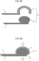
- Fig. 3 is a plan view of a gas adsorption device structure in the second exemplary embodiment of the present invention.
- Fig. 4A is a sectional view taken along line 4-4 in Fig. 3 .
- Fig. 4B is a sectional view in another state taken along line 4-4 in Fig. 3 .
- Components same as the first exemplary embodiment are given the same marks in the description.
- Gas adsorption device structure 10 in this exemplary embodiment has opening-and-closing structure 6. More specifically, outer package 2 is made of a low-density polyethylene film, and its three sides around rectangle are welded. Opening-and-closing structure 6 is formed on remaining one side. As shown in Fig. 4A , opening-and-closing structure 6 are configured with concave portion 61 formed at an end of one outer package 2 and convex portion 62 formed at an end of the other outer package 2. Concave portion 61 and convex portion 62 are linearly formed in the plan view. In addition, convex portion 61 and concave portion 62 are formed at positions facing each other.
- concave portion 61 and convex portion 62 are airtightly fitted by being pushed from the direction of arrow. Accordingly, air is sealed inside outer package 2. Since opening-and-closing structure 6 has this kind of mechanical structure, fitting can be released by applying a force in a direction opposite to the arrow in Fig. 4B . Gas adsorption device structure 10 can thus be opened to easily take out gas adsorption device 1. Furthermore, opening-and-closing structure 6 can be repeatedly opened and closed. Accordingly, outer package 2 can be reused.
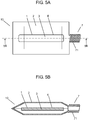
- Fig. 5A is a plan view of a gas adsorption device structure in the third exemplary embodiment of the present invention.
- Fig. 5B is a sectional view taken along line 5B-5B in Fig. 5A .
- Fig. 6A is a plan view of the gas adsorption device structure in another state in the third exemplary embodiment of the present invention.
- Fig. 6B is a sectional view taken along line 6B-6B. Components same as the first exemplary embodiment are given the same marks in the description.
- a point that differs from the second exemplary embodiment in this exemplary embodiment is that opening-and-closing structure 7 using a screw is provided as a mechanical opening-and-closing structure.
- gas adsorption device structure 10 has opening-and-closing structure 7 using a screw at an end.
- Outer package 2 is made of a low-density polyethylene film, same as the second exemplary embodiment, and three sides around rectangle are welded.
- Cap 72 is screwed to male screw 1 formed on remaining one side, as shown in Figs. 6A and 6B .
- a female screw (not illustrated) corresponding to male screw 71 is formed inside cap 72.
- opening-and-closing structure 7 Since a screw is used as opening-and-closing structure 7, it is easy to open gas adsorption device structure 10 and take out gas adsorption device 1.
- the size of gas adsorption device 1 is smaller than inner diameter of male screw 71. Furthermore, opening-and-closing structure 7 can be repeatedly opened and closed. Accordingly, outer package 2 can be reused.
- mechanical structures of opening-and-closing structure 6 and opening-and-closing structure 7 are not irreversible fixed structures, such as bonding in a molecular level. They have a structure that multiple components are fixed by external stress.
- Other mechanical opening-and-closing structure 6 or opening-and-closing structure 7 includes wedge, hinge, rubber band, and spring.
- gas adsorption device structure 10 in the first exemplary embodiment is used.
- Gas adsorption device 1 is prepared by sealing gas adsorbent 3 (2 g) formed of CuZSM-5 in container 4 configured with 0.2-mm thick aluminum.
- Outer package 2 is made by laminating a 50- ⁇ m thick low-density polyethylene film and a 25- ⁇ m thick biaxially-stretched nylon film. Outer package 2 is shaped like a bag using the low-density polyethylene film as a thermal welding layer. After placing gas adsorption device 1 in outer package 2, outer package 2 is sealed by thermal welding. This completes gas adsorption device structure 10.
- a volume of outer package 2 immediately after sealing gas adsorption device 1 was 5.5 cc. At this point, an adhesion level of gas adsorption device 1 and outer package 2 was 80%.
- the amount of air adsorption in specimens that have not been dropped was 10 cc.
- the amount of air adsorption in specimens without leak that have been dropped and stored for one month was 10 cc.
- the amount of air adsorbed in specimens with leak that have been dropped and stored for one month was 4.5 cc.
- Example 2 gas adsorption device structure 10 same as Example 1 is prepared. A volume of outer package 2 immediately after sealing gas adsorption device 1 was 8.5 cc. At this point, the adhesion level of gas adsorption device 1 and outer package 2 was 50%.
- Example 1 An amount of air adsorption was measured in specimens that have not been dropped, specimens without leak that have been dropped and stored for one month, and specimens with leak that have been dropped and stored for one month.
- the measuring method and measuring conditions were the same as Example 1.
- the amount of air adsorption in specimens that have not been dropped was 10 cc.
- the amount of air adsorption in specimens without leak that have been dropped and stored for one month was 10 C.
- the amount of air adsorption of specimens with leak that have been dropped and stored for one month was 1.5 cc.
- Example 3 gas adsorption device structure 10 same as Example 1 is prepared. A volume of outer package 2 immediately after sealing gas adsorption device was 15.5 cc. At this point, the adhesion level of gas adsorption device 1 and outer package 2 was 10%.
- Example 1 As specimens, 1000 pieces of above gas adsorption device structure 10 were prepared, and they were dropped and stored under the same conditions as Example 1. As a result, all 1000 pieces retained the adhesion level of 10%. An amount of air adsorption was measured in these specimens and specimens that have not been dropped, same as Example 1. The measuring method and measuring conditions were the same as Example 1.
- gas adsorption device structure 10 has good impact resistance when the adhesion level of gas adsorption device 1 and outer package 2 is 10%.
- Example 4 gas adsorption device structures 10 same as Example 1 with and without notch 5 on outer package 2 are prepared. To take out gas adsorption device 1, a tensile stress is applied to outer package 2 to open outer package 2.
- notch 5 facilitates opening of outer package 2. Accordingly, man-hour can be reduced at installing gas adsorption device 1 in vacuum equipment.
- Example 5 uses gas adsorption device structure 10 in the second exemplary embodiment.
- Gas adsorption device 1 is prepared by sealing gas adsorbent 3 (2g) made of CuZSM-5 in container 4 configured with 0.2-mm thick aluminum.
- Outer package 2 is formed of 200- ⁇ m thick low-density polyethylene.
- Outer package 2 has mechanical opening-and-closing structure 6.
- a volume of outer package 2 immediately after sealing gas adsorption device 1 was 7.5 cc. At this point the adhesion level of adsorption device 1 and outer package 2 was 70%.
- Example 2 An amount of air adsorption was measured in specimens that have not been dropped, specimens without leak that have been dropped and stored for one month, and specimens with leak that have been dropped and stored.
- the measuring method and measuring conditions were the same as Example 1.
- Gas adsorption device 1 can be taken out by releasing the fitting of opening-and-closing structure 6.
- the amount of air adsorption in specimens that have not been dropped was 10 cc.
- the amount of air adsorption in specimens without leak that have been dropped and stored for one month was 10cc.
- the amount of air adsorption in specimens with leak that have been dropped and stored for one month was 0 cc.
- the volume of outer package 2 of the specimens with leak has changed from 7.5 cc to 3 cc. In other words, 4.5 cc of air has reduced.
- the amount of air adsorption was 10 cc when there was no leak, and 0 cc when there was leak. In other words, the amount of air adsorption was 10 cc.
- An amount of reduced air i.e., 4.5 cc, does not correspond to the amount of adsorbed air, i.e., 10 cc. This is because air has entered through opening-and-closing structure 6 of outer package 2.
- Example 6 uses gas adsorption device structure 10 in the third exemplary embodiment.
- Gas adsorption device 1 is prepared by sealing gas adsorbent 3 (2g) formed of CuZSM in container 4 configured with 0.2-mm thick aluminum.
- Outer package 2 is made by laminating a 50- ⁇ m thick low-density polyethylene film and a 25- ⁇ m thick nylon film. The low-density polyethylene film is sealed at four sides as a thermal welding layer in outer package 2. It has mechanical opening-and-closing structure 7. Opening-and-closing structure 7 is configured with male screw 71 and cap 72 having female screw. Male screw 71 is hollow inside for taking in and out gas adsorption device 1.
- a volume of outer package 2 immediately after sealing gas adsorption device 1 was 5.5 cc. At this point, the adhesion level of gas adsorption device 1 and outer package 2 was 80%.
- Example 2 An amount of air adsorption was measured in specimens that have not been dropped, specimens without leak that have been dropped and stored for one month, and specimens with leak that have been dropped and stored for one month.
- the measuring method and measuring conditions were the same as Example 1.
- Gas adsorption device 1 can be taken out by removing cap 72 of opening-and-closing structure 7.
- the amount of air adsorption of specimens that have not been dropped was 10 cc.
- the amount of gas adsorption of specimens without leak that have been dropped and retained for one month was 10 cc.
- the amount of gas adsorption of specimens with leak that have been dropped and stored for one month was 0 cc.
- a volume of outer package 2 of specimens with leak has changed from 5.5 cc to 3 cc. In other words, air has reduced for 2.5 cc.
- the amount of air adsorption when there was no leak was 10 cc, and 0 cc when there was leak.
- the amount of gas adsorption was 10 cc.
- the amount of air that has been reduced, i.e., 2.5 cc, does not correspond to the amount of adsorbed air, i.e., 10 cc. This is because air has entered from outside through opening-and-closing structure 7 of outer package.
- gas adsorption device 1 of Example 1 is stored for one month without placing it in outer package 2 as a conventional storage method.
- the amount of air adsorption of gas adsorption device 1 before and after storage is measured.
- the measuring method and measuring conditions are the same as Example 1.
- the amount of gas adsorption before storage was 10 cc.
- the amount of gas adsorption after storage was 9.7 cc. Accordingly, leak occurred for 0.3 cc. However, occurrence of this leak cannot be determined.
- gas adsorption device 1 of Example 1 is placed in a 0.5-mm thick iron container without placing it in outer package 2, and stored for one month. After storage, the iron container is opened, and gas adsorption device 1 is disposed in a vacuum insulator after 10 minutes. A volume of the iron container was 25 cc both before and after storage. As a reference, gas adsorption device 1 immediately after it was prepared was also disposed in a vacuum insulator.
- the amount of air adsorption in these pieces was measured using the measuring method and measuring conditions same as Example 1. As a result, the amount of gas adsorption in gas adsorption device 1 immediately after it was prepared was 5 cc. On the other hand, the amount of air adsorption of gas adsorption device 1 after storing it in the iron container for one month was 3.5 cc.
- the volume of iron container has not changed even though the adsorption amount of gas adsorption device 1 has reduced for 1.5 cc. It is apparent that reduction in the amount of air adsorption in gas adsorption device 1 cannot be determined if gas adsorption device 1 is stored in 0.5-mm thick iron container. This is because the 0.5-mm thick iron container does not easily deform under atmospheric pressure. Accordingly, outer package 2 needs to be formed of a flexible material.
- the present invention can determine any performance degradation of a gas adsorption device by a change in the shape of the outer package. Accordingly, the present invention is suitable for quality inspection and storage of gas adsorption devices.
Landscapes
- Chemical & Material Sciences (AREA)
- Analytical Chemistry (AREA)
- Chemical Kinetics & Catalysis (AREA)
- Organic Chemistry (AREA)
- Engineering & Computer Science (AREA)
- Oil, Petroleum & Natural Gas (AREA)
- General Chemical & Material Sciences (AREA)
- Inorganic Chemistry (AREA)
- Food Science & Technology (AREA)
- Mechanical Engineering (AREA)
- Packages (AREA)
- Solid-Sorbent Or Filter-Aiding Compositions (AREA)
- Separation Of Gases By Adsorption (AREA)
Claims (7)
- Gasadsorptionsvorrichtungsstruktur (10) enthaltend:eine Gasadsorptionsvorrichtung (1), in der ein Gasadsorptionsmittel (3) durch eine erste Verpackung (4) mit schlechter Gasdurchlässigkeit dekompressionsversiegelt ist; undeine zweite Verpackung (2) mit schlechter Gasdurchlässigkeit zum Abdichten der Gasadsorptionsvorrichtung (1), wobei die zweite Verpackung (2) zumindest teilweise flexibel ist;wobeinur die Gasadsorptionsvorrichtung (1) in der zweiten Verpackung (2) angeordnet ist, und ein Gas, das das Gasadsorptionsmittel (3) absorbieren kann, zwischen der Gasadsorptionsvorrichtung (1) und der zweiten Verpackung (2) eingefüllt ist, sodass ein Teil der Gasadsorptionsvorrichtung (1) und der äußeren Verpackung (2) keinen Kontakt haben.
- Gasadsorptionsvorrichtungsstruktur (10) nach Anspruch 1, wobei ein Druck des Gases durch das Gasadsorptionsmittel (3), das das Gas adsorbiert, abnimmt, wenn eine Innenseite mit einer Außenseite der ersten Verpackung (4) aufgrund einer Beschädigung der ersten Verpackung (4) in Verbindung steht, und sich eine Form und/oder eine Abmessung der zweiten Verpackung (2) ändert.
- Gasadsorptionsvorrichtungsstruktur (10) nach Anspruch 1, wobei die zweite Verpackung (2) einen transparenten Teil zumindest an einer Stelle aufweist, an der die Gasadsorptionsvorrichtung (1) visuell erkennbar ist.
- Gasadsorptionsvorrichtungsstruktur (10) nach Anspruch 1, wobei die zweite Verpackung (2) zumindest teilweise eingekerbt ist.
- Gasadsorptionsvorrichtungsstruktur (10) nach Anspruch 1, wobei die zweite Verpackung eine Öffnungs- und Schließstruktur (6, 7) aufweist.
- Gasadsorptionsvorrichtungsstruktur (10) nach Anspruch 1, wobei das Gasadsorptionsmittel (3) CuZSM-5 ist.
- Verfahren zum Verwenden der Gasadsorptionsvorrichtungsstruktur (10) nach einem der Ansprüche 1 bis 6, wobei das Verfahren den Schritt enthält:Auswählen der Gasadsorptionsvorrichtungsstruktur (10) mit der zweiten Verpackung (2) einer vorbestimmten Form;Öffnen der zweiten Verpackung (2) der Gasadsorptionsvorrichtungsstruktur (10); undEntnahme der Gasadsorptionsvorrichtung (1) aus der Gasadsorptionsvorrichtungsstruktur (10).
Applications Claiming Priority (2)
| Application Number | Priority Date | Filing Date | Title |
|---|---|---|---|
| JP2010072038 | 2010-03-26 | ||
| PCT/JP2011/001369 WO2011118142A1 (ja) | 2010-03-26 | 2011-03-09 | 気体吸着デバイス構造体とその使用方法 |
Publications (3)
| Publication Number | Publication Date |
|---|---|
| EP2554491A1 EP2554491A1 (de) | 2013-02-06 |
| EP2554491A4 EP2554491A4 (de) | 2013-04-03 |
| EP2554491B1 true EP2554491B1 (de) | 2018-08-08 |
Family
ID=44672723
Family Applications (1)
| Application Number | Title | Priority Date | Filing Date |
|---|---|---|---|
| EP11758954.9A Not-in-force EP2554491B1 (de) | 2010-03-26 | 2011-03-09 | Gasadsorptionsvorrichtungsstruktur und verfahren für deren verwendung |
Country Status (6)
| Country | Link |
|---|---|
| US (1) | US8778057B2 (de) |
| EP (1) | EP2554491B1 (de) |
| JP (1) | JP5845422B2 (de) |
| KR (1) | KR101775744B1 (de) |
| CN (1) | CN102822070B (de) |
| WO (1) | WO2011118142A1 (de) |
Families Citing this family (18)
| Publication number | Priority date | Publication date | Assignee | Title |
|---|---|---|---|---|
| JP5261616B2 (ja) * | 2011-02-14 | 2013-08-14 | パナソニック株式会社 | 気体吸着デバイス及びそれを備えた真空断熱材 |
| TWI531405B (zh) | 2014-12-15 | 2016-05-01 | 財團法人工業技術研究院 | 氫洩漏吸附裝置、氫能利用系統、及氫洩漏吸附方法 |
| WO2016111006A1 (ja) * | 2015-01-09 | 2016-07-14 | 株式会社ニデック | レンズ染色用基体梱包物、レンズ染色用基体梱包部材、レンズ染色用基体梱包方法、及びレンズの染色方法。 |
| EP3332193B1 (de) | 2015-08-03 | 2021-11-17 | LG Electronics Inc. | Adiabatischer vakuumkörper |
| KR102466469B1 (ko) | 2015-08-03 | 2022-11-11 | 엘지전자 주식회사 | 진공단열체 및 냉장고 |
| KR102442973B1 (ko) | 2015-08-03 | 2022-09-14 | 엘지전자 주식회사 | 진공단열체 및 냉장고 |
| KR102529853B1 (ko) * | 2015-08-03 | 2023-05-08 | 엘지전자 주식회사 | 진공단열체, 진공단열체의 제조방법, 다공성물질패키지, 및 냉장고 |
| KR102525551B1 (ko) | 2015-08-03 | 2023-04-25 | 엘지전자 주식회사 | 진공단열체 및 냉장고 |
| KR102502160B1 (ko) | 2015-08-03 | 2023-02-21 | 엘지전자 주식회사 | 진공단열체 및 냉장고 |
| KR102447245B1 (ko) | 2015-08-03 | 2022-09-27 | 엘지전자 주식회사 | 진공단열체 및 냉장고 |
| KR102498210B1 (ko) | 2015-08-03 | 2023-02-09 | 엘지전자 주식회사 | 진공단열체 및 냉장고 |
| KR102525550B1 (ko) | 2015-08-03 | 2023-04-25 | 엘지전자 주식회사 | 진공단열체 및 냉장고 |
| KR102529852B1 (ko) | 2015-08-03 | 2023-05-08 | 엘지전자 주식회사 | 진공단열체 및 냉장고 |
| KR102456642B1 (ko) | 2015-08-03 | 2022-10-19 | 엘지전자 주식회사 | 진공단열체 및 냉장고 |
| KR20170016188A (ko) | 2015-08-03 | 2017-02-13 | 엘지전자 주식회사 | 진공단열체 및 냉장고 |
| KR102466470B1 (ko) | 2015-08-04 | 2022-11-11 | 엘지전자 주식회사 | 진공단열체 및 냉장고 |
| JP6508162B2 (ja) * | 2016-10-25 | 2019-05-08 | トヨタ自動車株式会社 | 真空断熱パネルの製造方法 |
| CN118988275B (zh) * | 2024-10-23 | 2025-01-24 | 山西绿远再生资源科技有限公司 | 一种活性炭再生设备 |
Family Cites Families (13)
| Publication number | Priority date | Publication date | Assignee | Title |
|---|---|---|---|---|
| JPS59137777A (ja) * | 1983-01-25 | 1984-08-07 | 松下冷機株式会社 | 断熱体パツク |
| US4502876A (en) * | 1984-01-03 | 1985-03-05 | Behnke Jr Albert R | Cartridge for use in rebreathing apparatus |
| US4726974A (en) * | 1986-10-08 | 1988-02-23 | Union Carbide Corporation | Vacuum insulation panel |
| IT1246785B (it) | 1991-04-16 | 1994-11-26 | Getters Spa | Contenitore di protezione temporanea per un materiale getter |
| AU2002353420A1 (en) * | 2002-12-30 | 2004-07-22 | World Wide Sales Inc. | Method for eliminating bad environmental odor |
| JP4204423B2 (ja) * | 2003-09-19 | 2009-01-07 | 紺藤 智子 | 粒状吸着材および吸着装置 |
| JP2006153150A (ja) * | 2004-11-30 | 2006-06-15 | Kurabo Ind Ltd | 真空断熱材 |
| JP5256597B2 (ja) * | 2006-09-01 | 2013-08-07 | パナソニック株式会社 | 気体吸着デバイスおよび真空断熱材 |
| WO2007034906A1 (ja) | 2005-09-26 | 2007-03-29 | Matsushita Electric Industrial Co., Ltd. | 気体吸着デバイス、気体吸着デバイスを用いた真空断熱体および真空断熱体の製造方法 |
| CN2857909Y (zh) * | 2005-09-30 | 2007-01-17 | 杨文渊 | 微型自热取暖片 |
| JP2008200616A (ja) * | 2007-02-21 | 2008-09-04 | Matsushita Electric Ind Co Ltd | 気体吸着デバイス |
| JP4867699B2 (ja) * | 2007-02-21 | 2012-02-01 | パナソニック株式会社 | 気体吸着デバイス |
| JP5254588B2 (ja) | 2007-10-12 | 2013-08-07 | 日本特殊陶業株式会社 | 固体酸化物形燃料電池モジュール |
-
2011
- 2011-03-09 EP EP11758954.9A patent/EP2554491B1/de not_active Not-in-force
- 2011-03-09 CN CN201180016170.3A patent/CN102822070B/zh not_active Expired - Fee Related
- 2011-03-09 JP JP2012506795A patent/JP5845422B2/ja not_active Expired - Fee Related
- 2011-03-09 KR KR1020127025046A patent/KR101775744B1/ko not_active Expired - Fee Related
- 2011-03-09 WO PCT/JP2011/001369 patent/WO2011118142A1/ja not_active Ceased
- 2011-03-09 US US13/636,068 patent/US8778057B2/en not_active Expired - Fee Related
Non-Patent Citations (1)
| Title |
|---|
| None * |
Also Published As
| Publication number | Publication date |
|---|---|
| US8778057B2 (en) | 2014-07-15 |
| WO2011118142A1 (ja) | 2011-09-29 |
| EP2554491A4 (de) | 2013-04-03 |
| CN102822070B (zh) | 2015-04-08 |
| EP2554491A1 (de) | 2013-02-06 |
| KR20130033359A (ko) | 2013-04-03 |
| US20130008309A1 (en) | 2013-01-10 |
| JPWO2011118142A1 (ja) | 2013-07-04 |
| KR101775744B1 (ko) | 2017-09-19 |
| CN102822070A (zh) | 2012-12-12 |
| JP5845422B2 (ja) | 2016-01-20 |
Similar Documents
| Publication | Publication Date | Title |
|---|---|---|
| EP2554491B1 (de) | Gasadsorptionsvorrichtungsstruktur und verfahren für deren verwendung | |
| US9205368B2 (en) | Gas adsorbing device and hollow body housing the same | |
| EP1903271B1 (de) | Gasapsorptionsvorrichtung, vakuumwärmeschutz mit der gasapsorptionsvorrichtung und verfahren zur herstellung eines vakuumwärmeschutzes | |
| JP2020053381A (ja) | 蓄電デバイス用弁装置及び蓄電デバイス | |
| EP1754971A1 (de) | Schnelldiagnosestreifen mit feuchtigkeitsabsorbierendem material und blisterpackung dafür | |
| WO2024006116A1 (en) | Cassette bags for transporting biomaterials | |
| CN113228395B (zh) | 阀装置和电池组 | |
| JP2020053179A (ja) | 蓄電デバイス用弁装置及び蓄電デバイス | |
| JPH11278580A (ja) | 帯状物品巻回体包装具並びに防湿包装フィルム及び包装体 | |
| JP4986789B2 (ja) | 検体運搬容器 | |
| JP2017217208A (ja) | 内視鏡部品の包装体および内視鏡部品の管理方法 | |
| CN100506665C (zh) | 电极用部件包装体 | |
| JP2020053387A (ja) | 蓄電デバイス用弁装置及び蓄電デバイス | |
| JP2017052553A (ja) | 保冷保温用箱体およびその組み立て方法 | |
| JP2010083510A (ja) | 常温収縮チューブユニット梱包体 |
Legal Events
| Date | Code | Title | Description |
|---|---|---|---|
| PUAI | Public reference made under article 153(3) epc to a published international application that has entered the european phase |
Free format text: ORIGINAL CODE: 0009012 |
|
| 17P | Request for examination filed |
Effective date: 20121026 |
|
| AK | Designated contracting states |
Kind code of ref document: A1 Designated state(s): AL AT BE BG CH CY CZ DE DK EE ES FI FR GB GR HR HU IE IS IT LI LT LU LV MC MK MT NL NO PL PT RO RS SE SI SK SM TR |
|
| A4 | Supplementary search report drawn up and despatched |
Effective date: 20130306 |
|
| RIC1 | Information provided on ipc code assigned before grant |
Ipc: B65D 85/84 20060101AFI20130228BHEP Ipc: B65D 85/00 20060101ALI20130228BHEP Ipc: B01D 53/04 20060101ALI20130228BHEP Ipc: B65D 77/04 20060101ALI20130228BHEP Ipc: B01J 20/18 20060101ALI20130228BHEP Ipc: B65D 81/26 20060101ALI20130228BHEP |
|
| DAX | Request for extension of the european patent (deleted) | ||
| 17Q | First examination report despatched |
Effective date: 20160818 |
|
| STAA | Information on the status of an ep patent application or granted ep patent |
Free format text: STATUS: EXAMINATION IS IN PROGRESS |
|
| GRAP | Despatch of communication of intention to grant a patent |
Free format text: ORIGINAL CODE: EPIDOSNIGR1 |
|
| STAA | Information on the status of an ep patent application or granted ep patent |
Free format text: STATUS: GRANT OF PATENT IS INTENDED |
|
| INTG | Intention to grant announced |
Effective date: 20171009 |
|
| GRAJ | Information related to disapproval of communication of intention to grant by the applicant or resumption of examination proceedings by the epo deleted |
Free format text: ORIGINAL CODE: EPIDOSDIGR1 |
|
| STAA | Information on the status of an ep patent application or granted ep patent |
Free format text: STATUS: EXAMINATION IS IN PROGRESS |
|
| GRAP | Despatch of communication of intention to grant a patent |
Free format text: ORIGINAL CODE: EPIDOSNIGR1 |
|
| STAA | Information on the status of an ep patent application or granted ep patent |
Free format text: STATUS: GRANT OF PATENT IS INTENDED |
|
| INTC | Intention to grant announced (deleted) | ||
| INTG | Intention to grant announced |
Effective date: 20180221 |
|
| GRAS | Grant fee paid |
Free format text: ORIGINAL CODE: EPIDOSNIGR3 |
|
| GRAA | (expected) grant |
Free format text: ORIGINAL CODE: 0009210 |
|
| STAA | Information on the status of an ep patent application or granted ep patent |
Free format text: STATUS: THE PATENT HAS BEEN GRANTED |
|
| AK | Designated contracting states |
Kind code of ref document: B1 Designated state(s): AL AT BE BG CH CY CZ DE DK EE ES FI FR GB GR HR HU IE IS IT LI LT LU LV MC MK MT NL NO PL PT RO RS SE SI SK SM TR |
|
| REG | Reference to a national code |
Ref country code: GB Ref legal event code: FG4D |
|
| REG | Reference to a national code |
Ref country code: CH Ref legal event code: EP Ref country code: AT Ref legal event code: REF Ref document number: 1026704 Country of ref document: AT Kind code of ref document: T Effective date: 20180815 |
|
| REG | Reference to a national code |
Ref country code: IE Ref legal event code: FG4D |
|
| REG | Reference to a national code |
Ref country code: DE Ref legal event code: R096 Ref document number: 602011050846 Country of ref document: DE |
|
| REG | Reference to a national code |
Ref country code: NL Ref legal event code: MP Effective date: 20180808 |
|
| REG | Reference to a national code |
Ref country code: LT Ref legal event code: MG4D |
|
| REG | Reference to a national code |
Ref country code: AT Ref legal event code: MK05 Ref document number: 1026704 Country of ref document: AT Kind code of ref document: T Effective date: 20180808 |
|
| PG25 | Lapsed in a contracting state [announced via postgrant information from national office to epo] |
Ref country code: NO Free format text: LAPSE BECAUSE OF FAILURE TO SUBMIT A TRANSLATION OF THE DESCRIPTION OR TO PAY THE FEE WITHIN THE PRESCRIBED TIME-LIMIT Effective date: 20181108 Ref country code: FI Free format text: LAPSE BECAUSE OF FAILURE TO SUBMIT A TRANSLATION OF THE DESCRIPTION OR TO PAY THE FEE WITHIN THE PRESCRIBED TIME-LIMIT Effective date: 20180808 Ref country code: AT Free format text: LAPSE BECAUSE OF FAILURE TO SUBMIT A TRANSLATION OF THE DESCRIPTION OR TO PAY THE FEE WITHIN THE PRESCRIBED TIME-LIMIT Effective date: 20180808 Ref country code: RS Free format text: LAPSE BECAUSE OF FAILURE TO SUBMIT A TRANSLATION OF THE DESCRIPTION OR TO PAY THE FEE WITHIN THE PRESCRIBED TIME-LIMIT Effective date: 20180808 Ref country code: GR Free format text: LAPSE BECAUSE OF FAILURE TO SUBMIT A TRANSLATION OF THE DESCRIPTION OR TO PAY THE FEE WITHIN THE PRESCRIBED TIME-LIMIT Effective date: 20181109 Ref country code: PL Free format text: LAPSE BECAUSE OF FAILURE TO SUBMIT A TRANSLATION OF THE DESCRIPTION OR TO PAY THE FEE WITHIN THE PRESCRIBED TIME-LIMIT Effective date: 20180808 Ref country code: LT Free format text: LAPSE BECAUSE OF FAILURE TO SUBMIT A TRANSLATION OF THE DESCRIPTION OR TO PAY THE FEE WITHIN THE PRESCRIBED TIME-LIMIT Effective date: 20180808 Ref country code: IS Free format text: LAPSE BECAUSE OF FAILURE TO SUBMIT A TRANSLATION OF THE DESCRIPTION OR TO PAY THE FEE WITHIN THE PRESCRIBED TIME-LIMIT Effective date: 20181208 Ref country code: NL Free format text: LAPSE BECAUSE OF FAILURE TO SUBMIT A TRANSLATION OF THE DESCRIPTION OR TO PAY THE FEE WITHIN THE PRESCRIBED TIME-LIMIT Effective date: 20180808 Ref country code: SE Free format text: LAPSE BECAUSE OF FAILURE TO SUBMIT A TRANSLATION OF THE DESCRIPTION OR TO PAY THE FEE WITHIN THE PRESCRIBED TIME-LIMIT Effective date: 20180808 Ref country code: BG Free format text: LAPSE BECAUSE OF FAILURE TO SUBMIT A TRANSLATION OF THE DESCRIPTION OR TO PAY THE FEE WITHIN THE PRESCRIBED TIME-LIMIT Effective date: 20181108 |
|
| PG25 | Lapsed in a contracting state [announced via postgrant information from national office to epo] |
Ref country code: LV Free format text: LAPSE BECAUSE OF FAILURE TO SUBMIT A TRANSLATION OF THE DESCRIPTION OR TO PAY THE FEE WITHIN THE PRESCRIBED TIME-LIMIT Effective date: 20180808 Ref country code: AL Free format text: LAPSE BECAUSE OF FAILURE TO SUBMIT A TRANSLATION OF THE DESCRIPTION OR TO PAY THE FEE WITHIN THE PRESCRIBED TIME-LIMIT Effective date: 20180808 Ref country code: HR Free format text: LAPSE BECAUSE OF FAILURE TO SUBMIT A TRANSLATION OF THE DESCRIPTION OR TO PAY THE FEE WITHIN THE PRESCRIBED TIME-LIMIT Effective date: 20180808 |
|
| PG25 | Lapsed in a contracting state [announced via postgrant information from national office to epo] |
Ref country code: ES Free format text: LAPSE BECAUSE OF FAILURE TO SUBMIT A TRANSLATION OF THE DESCRIPTION OR TO PAY THE FEE WITHIN THE PRESCRIBED TIME-LIMIT Effective date: 20180808 Ref country code: CZ Free format text: LAPSE BECAUSE OF FAILURE TO SUBMIT A TRANSLATION OF THE DESCRIPTION OR TO PAY THE FEE WITHIN THE PRESCRIBED TIME-LIMIT Effective date: 20180808 Ref country code: RO Free format text: LAPSE BECAUSE OF FAILURE TO SUBMIT A TRANSLATION OF THE DESCRIPTION OR TO PAY THE FEE WITHIN THE PRESCRIBED TIME-LIMIT Effective date: 20180808 Ref country code: EE Free format text: LAPSE BECAUSE OF FAILURE TO SUBMIT A TRANSLATION OF THE DESCRIPTION OR TO PAY THE FEE WITHIN THE PRESCRIBED TIME-LIMIT Effective date: 20180808 Ref country code: IT Free format text: LAPSE BECAUSE OF FAILURE TO SUBMIT A TRANSLATION OF THE DESCRIPTION OR TO PAY THE FEE WITHIN THE PRESCRIBED TIME-LIMIT Effective date: 20180808 |
|
| REG | Reference to a national code |
Ref country code: DE Ref legal event code: R097 Ref document number: 602011050846 Country of ref document: DE |
|
| PG25 | Lapsed in a contracting state [announced via postgrant information from national office to epo] |
Ref country code: SM Free format text: LAPSE BECAUSE OF FAILURE TO SUBMIT A TRANSLATION OF THE DESCRIPTION OR TO PAY THE FEE WITHIN THE PRESCRIBED TIME-LIMIT Effective date: 20180808 Ref country code: SK Free format text: LAPSE BECAUSE OF FAILURE TO SUBMIT A TRANSLATION OF THE DESCRIPTION OR TO PAY THE FEE WITHIN THE PRESCRIBED TIME-LIMIT Effective date: 20180808 Ref country code: DK Free format text: LAPSE BECAUSE OF FAILURE TO SUBMIT A TRANSLATION OF THE DESCRIPTION OR TO PAY THE FEE WITHIN THE PRESCRIBED TIME-LIMIT Effective date: 20180808 |
|
| PLBE | No opposition filed within time limit |
Free format text: ORIGINAL CODE: 0009261 |
|
| STAA | Information on the status of an ep patent application or granted ep patent |
Free format text: STATUS: NO OPPOSITION FILED WITHIN TIME LIMIT |
|
| 26N | No opposition filed |
Effective date: 20190509 |
|
| PG25 | Lapsed in a contracting state [announced via postgrant information from national office to epo] |
Ref country code: SI Free format text: LAPSE BECAUSE OF FAILURE TO SUBMIT A TRANSLATION OF THE DESCRIPTION OR TO PAY THE FEE WITHIN THE PRESCRIBED TIME-LIMIT Effective date: 20180808 |
|
| PG25 | Lapsed in a contracting state [announced via postgrant information from national office to epo] |
Ref country code: MC Free format text: LAPSE BECAUSE OF FAILURE TO SUBMIT A TRANSLATION OF THE DESCRIPTION OR TO PAY THE FEE WITHIN THE PRESCRIBED TIME-LIMIT Effective date: 20180808 |
|
| REG | Reference to a national code |
Ref country code: CH Ref legal event code: PL |
|
| GBPC | Gb: european patent ceased through non-payment of renewal fee |
Effective date: 20190309 |
|
| PG25 | Lapsed in a contracting state [announced via postgrant information from national office to epo] |
Ref country code: LU Free format text: LAPSE BECAUSE OF NON-PAYMENT OF DUE FEES Effective date: 20190309 |
|
| REG | Reference to a national code |
Ref country code: BE Ref legal event code: MM Effective date: 20190331 |
|
| PG25 | Lapsed in a contracting state [announced via postgrant information from national office to epo] |
Ref country code: CH Free format text: LAPSE BECAUSE OF NON-PAYMENT OF DUE FEES Effective date: 20190331 Ref country code: LI Free format text: LAPSE BECAUSE OF NON-PAYMENT OF DUE FEES Effective date: 20190331 Ref country code: GB Free format text: LAPSE BECAUSE OF NON-PAYMENT OF DUE FEES Effective date: 20190309 Ref country code: IE Free format text: LAPSE BECAUSE OF NON-PAYMENT OF DUE FEES Effective date: 20190309 |
|
| PG25 | Lapsed in a contracting state [announced via postgrant information from national office to epo] |
Ref country code: FR Free format text: LAPSE BECAUSE OF NON-PAYMENT OF DUE FEES Effective date: 20190331 Ref country code: BE Free format text: LAPSE BECAUSE OF NON-PAYMENT OF DUE FEES Effective date: 20190331 |
|
| PG25 | Lapsed in a contracting state [announced via postgrant information from national office to epo] |
Ref country code: TR Free format text: LAPSE BECAUSE OF FAILURE TO SUBMIT A TRANSLATION OF THE DESCRIPTION OR TO PAY THE FEE WITHIN THE PRESCRIBED TIME-LIMIT Effective date: 20180808 |
|
| PG25 | Lapsed in a contracting state [announced via postgrant information from national office to epo] |
Ref country code: PT Free format text: LAPSE BECAUSE OF FAILURE TO SUBMIT A TRANSLATION OF THE DESCRIPTION OR TO PAY THE FEE WITHIN THE PRESCRIBED TIME-LIMIT Effective date: 20181208 Ref country code: MT Free format text: LAPSE BECAUSE OF NON-PAYMENT OF DUE FEES Effective date: 20190309 |
|
| PG25 | Lapsed in a contracting state [announced via postgrant information from national office to epo] |
Ref country code: CY Free format text: LAPSE BECAUSE OF FAILURE TO SUBMIT A TRANSLATION OF THE DESCRIPTION OR TO PAY THE FEE WITHIN THE PRESCRIBED TIME-LIMIT Effective date: 20180808 |
|
| PGFP | Annual fee paid to national office [announced via postgrant information from national office to epo] |
Ref country code: DE Payment date: 20210319 Year of fee payment: 11 |
|
| PG25 | Lapsed in a contracting state [announced via postgrant information from national office to epo] |
Ref country code: HU Free format text: LAPSE BECAUSE OF FAILURE TO SUBMIT A TRANSLATION OF THE DESCRIPTION OR TO PAY THE FEE WITHIN THE PRESCRIBED TIME-LIMIT; INVALID AB INITIO Effective date: 20110309 |
|
| PG25 | Lapsed in a contracting state [announced via postgrant information from national office to epo] |
Ref country code: MK Free format text: LAPSE BECAUSE OF FAILURE TO SUBMIT A TRANSLATION OF THE DESCRIPTION OR TO PAY THE FEE WITHIN THE PRESCRIBED TIME-LIMIT Effective date: 20180808 |
|
| REG | Reference to a national code |
Ref country code: DE Ref legal event code: R119 Ref document number: 602011050846 Country of ref document: DE |
|
| PG25 | Lapsed in a contracting state [announced via postgrant information from national office to epo] |
Ref country code: DE Free format text: LAPSE BECAUSE OF NON-PAYMENT OF DUE FEES Effective date: 20221001 |