EP2554422B1 - Vorrichtung zur Steuerung der Antriebskraftverteilung und Fahrzeug mit Vierradantrieb - Google Patents
Vorrichtung zur Steuerung der Antriebskraftverteilung und Fahrzeug mit Vierradantrieb Download PDFInfo
- Publication number
- EP2554422B1 EP2554422B1 EP12178802.0A EP12178802A EP2554422B1 EP 2554422 B1 EP2554422 B1 EP 2554422B1 EP 12178802 A EP12178802 A EP 12178802A EP 2554422 B1 EP2554422 B1 EP 2554422B1
- Authority
- EP
- European Patent Office
- Prior art keywords
- driving force
- engine
- torque
- abnormal sound
- wheel
- Prior art date
- Legal status (The legal status is an assumption and is not a legal conclusion. Google has not performed a legal analysis and makes no representation as to the accuracy of the status listed.)
- Not-in-force
Links
- 230000002159 abnormal effect Effects 0.000 claims description 76
- 230000005540 biological transmission Effects 0.000 claims description 46
- 230000010349 pulsation Effects 0.000 claims description 6
- 238000001514 detection method Methods 0.000 description 9
- 238000012545 processing Methods 0.000 description 9
- 230000005284 excitation Effects 0.000 description 6
- 239000000446 fuel Substances 0.000 description 6
- 230000006866 deterioration Effects 0.000 description 4
- 238000012546 transfer Methods 0.000 description 4
- 230000002093 peripheral effect Effects 0.000 description 3
- 230000001133 acceleration Effects 0.000 description 2
- 238000002485 combustion reaction Methods 0.000 description 2
- 230000003247 decreasing effect Effects 0.000 description 2
- 238000010586 diagram Methods 0.000 description 2
- 238000004880 explosion Methods 0.000 description 2
- 238000004891 communication Methods 0.000 description 1
- 230000006835 compression Effects 0.000 description 1
- 238000007906 compression Methods 0.000 description 1
- 230000008878 coupling Effects 0.000 description 1
- 238000010168 coupling process Methods 0.000 description 1
- 238000005859 coupling reaction Methods 0.000 description 1
- 125000004122 cyclic group Chemical group 0.000 description 1
- 230000001419 dependent effect Effects 0.000 description 1
- 238000011161 development Methods 0.000 description 1
- 230000018109 developmental process Effects 0.000 description 1
- 230000000694 effects Effects 0.000 description 1
- 230000000116 mitigating effect Effects 0.000 description 1
- 238000011160 research Methods 0.000 description 1
- 230000000087 stabilizing effect Effects 0.000 description 1
- 238000012360 testing method Methods 0.000 description 1
Images
Classifications
-
- B—PERFORMING OPERATIONS; TRANSPORTING
- B60—VEHICLES IN GENERAL
- B60K—ARRANGEMENT OR MOUNTING OF PROPULSION UNITS OR OF TRANSMISSIONS IN VEHICLES; ARRANGEMENT OR MOUNTING OF PLURAL DIVERSE PRIME-MOVERS IN VEHICLES; AUXILIARY DRIVES FOR VEHICLES; INSTRUMENTATION OR DASHBOARDS FOR VEHICLES; ARRANGEMENTS IN CONNECTION WITH COOLING, AIR INTAKE, GAS EXHAUST OR FUEL SUPPLY OF PROPULSION UNITS IN VEHICLES
- B60K17/00—Arrangement or mounting of transmissions in vehicles
- B60K17/34—Arrangement or mounting of transmissions in vehicles for driving both front and rear wheels, e.g. four wheel drive vehicles
- B60K17/348—Arrangement or mounting of transmissions in vehicles for driving both front and rear wheels, e.g. four wheel drive vehicles having differential means for driving one set of wheels, e.g. the front, at one speed and the other set, e.g. the rear, at a different speed
- B60K17/35—Arrangement or mounting of transmissions in vehicles for driving both front and rear wheels, e.g. four wheel drive vehicles having differential means for driving one set of wheels, e.g. the front, at one speed and the other set, e.g. the rear, at a different speed including arrangements for suppressing or influencing the power transfer, e.g. viscous clutches
-
- B—PERFORMING OPERATIONS; TRANSPORTING
- B60—VEHICLES IN GENERAL
- B60K—ARRANGEMENT OR MOUNTING OF PROPULSION UNITS OR OF TRANSMISSIONS IN VEHICLES; ARRANGEMENT OR MOUNTING OF PLURAL DIVERSE PRIME-MOVERS IN VEHICLES; AUXILIARY DRIVES FOR VEHICLES; INSTRUMENTATION OR DASHBOARDS FOR VEHICLES; ARRANGEMENTS IN CONNECTION WITH COOLING, AIR INTAKE, GAS EXHAUST OR FUEL SUPPLY OF PROPULSION UNITS IN VEHICLES
- B60K23/00—Arrangement or mounting of control devices for vehicle transmissions, or parts thereof, not otherwise provided for
- B60K23/08—Arrangement or mounting of control devices for vehicle transmissions, or parts thereof, not otherwise provided for for changing number of driven wheels, for switching from driving one axle to driving two or more axles
- B60K23/0808—Arrangement or mounting of control devices for vehicle transmissions, or parts thereof, not otherwise provided for for changing number of driven wheels, for switching from driving one axle to driving two or more axles for varying torque distribution between driven axles, e.g. by transfer clutch
-
- B—PERFORMING OPERATIONS; TRANSPORTING
- B60—VEHICLES IN GENERAL
- B60K—ARRANGEMENT OR MOUNTING OF PROPULSION UNITS OR OF TRANSMISSIONS IN VEHICLES; ARRANGEMENT OR MOUNTING OF PLURAL DIVERSE PRIME-MOVERS IN VEHICLES; AUXILIARY DRIVES FOR VEHICLES; INSTRUMENTATION OR DASHBOARDS FOR VEHICLES; ARRANGEMENTS IN CONNECTION WITH COOLING, AIR INTAKE, GAS EXHAUST OR FUEL SUPPLY OF PROPULSION UNITS IN VEHICLES
- B60K23/00—Arrangement or mounting of control devices for vehicle transmissions, or parts thereof, not otherwise provided for
- B60K23/08—Arrangement or mounting of control devices for vehicle transmissions, or parts thereof, not otherwise provided for for changing number of driven wheels, for switching from driving one axle to driving two or more axles
- B60K2023/085—Arrangement or mounting of control devices for vehicle transmissions, or parts thereof, not otherwise provided for for changing number of driven wheels, for switching from driving one axle to driving two or more axles automatically actuated
- B60K2023/0858—Arrangement or mounting of control devices for vehicle transmissions, or parts thereof, not otherwise provided for for changing number of driven wheels, for switching from driving one axle to driving two or more axles automatically actuated with electric means, e.g. electro-hydraulic means
-
- B—PERFORMING OPERATIONS; TRANSPORTING
- B60—VEHICLES IN GENERAL
- B60W—CONJOINT CONTROL OF VEHICLE SUB-UNITS OF DIFFERENT TYPE OR DIFFERENT FUNCTION; CONTROL SYSTEMS SPECIALLY ADAPTED FOR HYBRID VEHICLES; ROAD VEHICLE DRIVE CONTROL SYSTEMS FOR PURPOSES NOT RELATED TO THE CONTROL OF A PARTICULAR SUB-UNIT
- B60W2510/00—Input parameters relating to a particular sub-units
- B60W2510/06—Combustion engines, Gas turbines
- B60W2510/0638—Engine speed
Definitions
- the present invention relates to a driving force distribution control device that controls driving force to be distributed to an auxiliary drive wheel, and relates to a four-wheel-drive vehicle.
- a driving force distribution control device which distributes driving force to an auxiliary drive wheel at a predetermined rate at which an abnormal vibration is not generated when a driving state of the four-wheel-drive vehicle is in an abnormal vibration generation region in which an abnormal sound due to the abnormal vibration caused by knocking of the engine is generated in a driving force transmission system (for example, JP-A-2001-277881 , in accordance with the preamble of claim 1 (Patent Document 1)).
- the driving force distribution control device disclosed in Patent Document 1 is configured so as to generate frictional torque suitable for mitigating the abnormal sound in a torque coupling when a vehicle speed exceeds a vibration generation lower limit speed and is less than a vibration generation upper limit speed.
- the frictional torque has a value higher than that in a case where the vehicle speed is not in the abnormal vibration generation region.
- the abnormal sound from the driving force transmitting system is not limited to that caused by knocking, and can also be generated by pulsation (cyclic fluctuation) of torque of the engine.
- pulsation cyclic fluctuation
- the present inventors have earnestly persisted in their research, focused on the fact that the engine torque is related to presence or absence of the generation of the abnormal sound, and found that, even if the number of revolutions of the engine is in a range in which the abnormal sound can be generated, the abnormal sound does not occur depending on a value of the engine torque and the driving force to be transmitted to the auxiliary drive wheel can be reduced in such a state.
- the object of the invention is achieved with a four-wheel-drive vehicle according to claim 1.
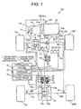
- Fig. 1 is a schematic diagram that shows a configuration example of a four-wheel-drive vehicle according to an embodiment of the present invention.
- a four-wheel-drive vehicle 100 is equipped with an engine 101 as a driving source, a transmission 103 as a gearbox that changes output of the engine 101, a clutch 102 which connects an output shaft 101a of the engine 101 and an input shaft 103a of the transmission 103, a driving force transmission system 110 which transmits output of the transmission 103 to a pair of left and right front wheels 104 (a left front wheels 104L and a right front wheels 104R) and a pair of left and right rear wheels 105 (a left rear wheels 105L and a right rear wheels 105R) so as to be switchable into a two-wheel-drive state and a four-wheel-drive state, and a driving force distribution control device 1.
- the driving force distribution control device 1 includes a driving force transmitting device 2 capable of adjusting transmission torque, and a control device 3 that controls the driving force transmitting device 2.
- the driving force transmitting device 2 is able to switch the running state of the four-wheel-drive vehicle 100 into the two-wheel-drive state and the four-wheel-drive state.
- a steering wheel 120 for controlling the vehicle by a driver, a steering wheel 120, an accelerator pedal 121, a brake pedal 122, a clutch pedal 123, and a shift lever 124 are provided.
- the engine 101 is an internal combustion engine which is supplied with fuel depending on an amount of depression of the accelerator pedal 121, and outputs driving force for causing the four-wheel-drive vehicle 100 to run, from the output shaft 101a connected to the clutch shaft.
- the clutch 102 includes a first disc 102a connected to the output shaft 101a of the engine, and a second disc 102b connected to the input shaft 103a of the transmission 103.
- the output shaft 101a of the engine 101 is connected with the input shaft 103a of the transmission 103 by the frictional engagement between the first disc 102a and the second disc 102b.
- the transmission 103 is a manual transmission that changes the gear ratio into a plurality of stages by the gear shift operation of a driver using the shift lever 124.
- the transmission 103 is, for example, 6-speed transmission capable of changing the gear ratio into six stages from a first speed to a sixth speed (during advancement).
- the driving force transmission system 110 includes a front differential device 112 which distributes torque to the left front wheels 104L and the right front wheels 104R, a gear mechanism 111 which transmits torque of the output shaft of the transmission 103 to a differential case 112a of the front differential device 112, a transfer 113 which includes an input gear 113a connected to the differential case 112a and an output gear 113b having a rotational axis perpendicular to the input gear 113a and meshed with the input gear 113a, a propeller shaft 114 connected to the output gear 113b, a driving force transmitting device 2, a pinion gear shaft 115 to which torque of the propeller shaft 114 is transmitted via the driving force transmitting device 2, and a rear differential device 116 which distributes torque transmitted to the pinion gear shaft 115 into the left rear wheels 105L and the right rear wheels 105R.
- a front differential device 112 which distributes torque to the left front wheels 104L and the right front wheels 104R
- a gear mechanism 111
- the driving force transmission system 110 includes drive shafts 112L and 112R respectively connected to a pair of side gears of the front differential device 112, and drive shafts 116L and 116R respectively connected to a pair of side gears of the rear differential device 116.
- the drive shafts 112L and 112R transmit torque to the left front wheel 104L and the right front wheel 104R, and the drive shafts 116L and 116R transmit torque to the left rear wheel 105L and the right rear wheel 105R.
- a ring gear 116b is provided on an outer peripheral portion of the differential case 116a of the rear differential device 116 in a relatively non-rotatable manner.
- the ring gear 116b is meshed with the gear part 115a of the pinion gear shaft 115 and transmits torque from the pinion gear shaft 115 to the differential case 116a.
- the transfer 113, the propeller shaft 114, the pinion gear shaft 115, the rear differential device 116, and the drive shafts 116L and 116R are an example of a driving force transmitting member that transmits driving force of the engine 101 to the rear wheels 105.
- the driving force transmission system 110 In the driving force transmission system 110, during running, torque output from the transmission 103 is always transmitted to the left front wheel 104L and the right front wheel 104R by the configuration mentioned above. Furthermore, torque is transmitted to the left rear wheel 105L and the right rear wheel 105R by the operation of the driving force transmitting device 2 depending on the running state of the four-wheel-drive vehicle 100 when required. That is, in the four-wheel-drive vehicle 100 of the present embodiment, the left front wheel 104L and the right front wheel 104R are main drive wheels and the left rear wheel 105L and the right rear wheel 105R are auxiliary drive wheels.
- the control device 3 constituting the driving force distribution control device 1 includes a storage 31 constituted by a ROM, a RAM or the like, a controller 32 constituted by a calculation processing device such as a CPU, and an electric current output circuit 33 controlled by the controller 32.
- the controller 32 is operated based on program stored in the storage 31, and thus, the control device 3 obtains a value of command torque to be transmitted to the rear wheels 105 by the calculation, based on a rotation difference between the front wheels 104 and the rear wheels 105 of the four-wheel-drive vehicle 100, the output torque of the engine 101, the selected gear stage of the transmission 103, the final reduction ratio in the driving force transmission system 110, the steering angle by the operation of the steering wheel 120 or the like.
- the electric current output circuit 33 supplies electric current depending on the command torque obtained by the calculation processing of the controller 32 to the driving force transmitting device 2.
- the electric current output circuit 33 is, for example, an inverter circuit that outputs electric current to be supplied from a battery (not shown) by adjusting an amount of electric current using a PWM (Pulse Width Modulation) control.
- PWM Pulse Width Modulation
- Detection signals of a steering angle sensor 300 for detecting the rotation of the steering shaft 120a connected to the steering wheel 120, an engine rotational speed sensor 301 for detecting the rotational speed (the number of revolutions per a time) of the output shaft 101a of the engine 101, an accelerator opening degree sensor 302 for detecting an accelerator opening degree (an amount of acceleration operation) depending on an amount of depression of the accelerator pedal 121, and a shift position sensor 303 for detecting the position of the shift lever 124 are input to the control device 3.
- detection signals of vehicle wheel speed sensors 304 to 307 which are respectively provided for the left front wheel 104L, the right front wheel 104R, the left rear wheel 105L, and the right rear wheel 105R to detect the rotational speed of each of the wheels, are input to the control device 3.
- the detection signals of the respective sensors 300 to 307 may be directly input to the control device 3 via signal lines connected to the sensor main body, and may be input to the control device 3 by communication through an in-vehicle network such as a CAN (Controller Area Network).
- CAN Controller Area Network
- the driving force transmitting device 2 includes a cylindrical outer housing 21 with a bottom, which is connected to the propeller shaft 114, a cylindrical inner shaft 22 connected to the pinion gear shaft 115, and a main clutch 23 formed of a plurality of frictional plates arranged between the inner peripheral surface of the outer housing 21 and the outer peripheral surface of the inner shaft 22.
- the main clutch 23 is constituted by alternately arranging a plurality of outer clutch plates 23a spline-fitted to the outer housing 21 in a relatively non-rotatable manner, and a plurality of inner clutch plates 23b spline-fitted to the inner shaft 22 in a relatively non-rotatable manner.
- annular electromagnetic coil 24 for generating pressing force axially pressing the main clutch 23, a pilot clutch 25 pressed by electromagnetic force of the electromagnetic coil 24, and a cam mechanism 26 for converting rotational force transmitted via the pilot clutch 25 into axial thrust force pressing the main clutch 23 are arranged.
- Excitation current is supplied from the electric current output circuit 33 (see Fig. 1 ) of the control device 3 to the electromagnetic coil 24.
- excitation current is supplied to the electromagnetic coil 24
- rotational force of the outer housing 21 is transmitted to the cam mechanism 26 via the pilot clutch 25 by the electromagnetic force of the electromagnetic coil 24, and thrust force pressing the main clutch 23 is generated by operation of the cam mechanism 26.
- driving force transmitted from the outer housing 21 to the inner shaft 22 is changed depending on excitation current supplied to the electromagnetic coil 24.
- the control device 3 controls an amount of transmission of torque of the driving force transmitting device 2 by adjusting the excitation current to be supplied to the excitation coil 24.
- the control device 3 has a normal control function of calculating a torque value to be transmitted to the rear wheels 105 based on the rotational speed difference between the front and rear wheels, the output torque of the engine 101, the selected gear stage of the transmission 103, the final reduction ratio in the driving force transmission system 110, the steering angle by the operation of the steering wheel 120 or the like, and supplying the excitation current depending on the calculated torque value to the electromagnetic coil 24 of the driving force transmitting device 2.
- control device 3 has an abnormal sound countermeasure control function of setting the torque value to be transmitted to the rear wheels 105 as a value capable of reducing the abnormal sound of the driving force transmission system 110 due to pulsation of driving force of the engine 101, when the gear stage of the transmission 103 selected by the operation of the shift lever 124 by a driver is a predetermined gear stage, and the rotational speed of the output shaft 101a of the engine 101 is in a predetermined range of a rotational speed.
- the normal control function and the abnormal sound countermeasure control function will be described.
- the controller 32 of the control device 3 calculates the command torque tc by the sum of a first torque t1 based on a rotational speed difference between the front wheels 104 and the rear wheels 105, a second torque t2 based on the output torque of the engine 101 and the selected gear stage of the transmission 103 or the like, and a third torque t3 based on the steering angle.
- a rotational speed Vf (an average rotational speed of the left and right front wheels 104L and 104R) of the front wheels 104 is calculated based on the detection signals of the vehicle wheel speed sensors 304 and 305 respectively provided for the left and right front wheels 104L and 104R
- a rotational speed Vr (an average rotational speed of the left and right rear wheels 105L and 105R) of the rear wheels 105 is calculated based on the detection signals of the vehicle wheel speed sensors 306 and 307 respectively provided for the left and right rear wheels 105L and 105R.
- the first torque t1 is obtained with reference to a first torque map, stored in the storage 31, indicating a relationship between the rotational speed difference ⁇ V and the first torque t1.
- the first torque map is set so that the greater the rotational speed difference ⁇ V, the greater the first torque t1.
- the first torque t1 may be changed by the vehicle speed S.
- the vehicle speed S can be obtained, for example, by multiplying the sum of the rotational speed Vf of the front wheels 104 and the rotational speed Vr of the rear wheels 105 by a predetermined factor.
- the second torque t2 is obtained with reference to a second torque map, stored in the storage 31, indicating a relationship between the second torque t2 and the sum (drive torque) of torque transmitted to the left and right front wheels 104L and 104R and the left and right rear wheels 105L and 105R.
- the drive torque can be obtained by the calculation, for example, based on the output torque of the engine 101, the selected gear stage of the transmission 103, and the final reduction ratio in the driving force transmission system 110.
- the second torque map is set so that, when the drive torque is less than a predetermined value, the second torque t2 is increased depending on an increase of the drive torque or is a constant value, and when the drive torque is equal to or greater than the predetermined value, the second torque t2 is increased depending on an increase of the drive torque by an increasing ratio greater than that in a case where the drive torque is less than the predetermined value.
- the predetermined value is a value that is set depending on a grip limit torque of the left and right front wheels 104L and 104R.
- the great driving force of the engine 101 at the time of the sudden acceleration is uniformly distributed to the front wheels 104 and the rear wheels 105, and thus it is possible to avoid the slip of the left front wheel 104L or the right front wheel 104R that can occur when the driving force is concentrated on the left and right front wheels 104L and 104R serving as main drive wheels.
- the second torque t2 may be further changed by the vehicle speed S.
- the steering angle of the steering shaft 120a is detected from the detection signal of the steering angle sensor 300, and the third torque t3 is obtained with reference to a third torque map, stored in the storage 31, indicating a relationship between the steering angle and the third torque t3.
- the third torque map is set so that, the greater the steering angle is, the greater the third torque t3 is.
- the third torque t3 may be further changed by the vehicle speed S.
- the controller 32 of the control device 3 suppresses the occurrence of abnormal sound by transmitting torque to the rear wheels 105 when the gear stage of the transmission 103 and the rotational speed of the output shaft 101a of the engine 101 are in a state where the abnormal sound can occur from the driving force transmission system 110 by the pulsation of the driving force of the engine 101.
- the engine serving as an internal combustion engine repeats a suction stroke, a compression stroke, an explosion stroke and an exhaust stroke, and generates driving force in the explosion stroke
- the driving force output from the engine is always pulsated even if the opening degree of the accelerator is constant.
- the cycle of the pulsation is changed depending on the rotational speed of the engine, and the lower the rotational speed is, the longer the cycle is.
- torque to be transmitted to the rear wheels is near zero, and in the two-wheel driving state in which the driving force is substantially transmitted only to the front wheels, when the engine is in the low rotation state, there is a possibility that the abnormal sound (gear rattling sound) is generated from the gear meshing portion in the transfer and the rear differential device.
- the controller 32 of the control device 3 by transmitting torque to the rear wheels 105 even in the two-wheel driving state, presses the driving force transmitting members with each other for transmitting the driving force of the engine 101 to the rear wheels 105 so that the gear meshing direction in the transfer 113 and the rear differential device 116 is not changed, that is, so that the switch-over of the contact state and the non-contact state between the gear teeth are not repeated, thereby to reduce the abnormal sound.
- the controller 32 changes torque to be transmitted to the rear wheels 105 depending on the driving force which is output from the engine 101.
- the driving force of the engine 101 (the driving force that is output from the engine) is an engine torque that is calculated and output by the calculation device of the four-wheel-drive vehicle 100 based on the detection result of the state of the engine 101.
- the driving force of the engine 101 may be calculated, for example, based on the accelerator opening degree detected by the accelerator opening degree sensor 302, or may be obtained with reference to information acquired from the control device of the engine 101.
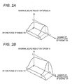
- the control device 3 stores relationship information indicating a relationship between the driving force of the engine 101, the number of revolutions (the rotational speed of the output shaft 101a) of the engine 101, and a torque value capable of reducing the abnormal sound (hereinafter, the torque value is referred to as a "abnormal sound reduction torque td"), in the storage 31 as a three-dimensional torque map.
- the torque maps are stored.
- Figs. 2A and 2B indicate examples of the torque maps
- Fig. 2A is a torque map of a case where the selected gear stage is the fifth speed
- Fig. 2B is a torque map of a case where the selected gear stage is the sixth speed.
- the abnormal sound countermeasure control is performed, and the abnormal sound reduction torque td becomes a peak value (t 1 ) in r 11 (1500 rpm). Furthermore, the abnormal sound reduction torque td is also changed by the driving force of the engine 101, and the value thereof is increased along with an increase of the driving force of the engine 101.
- the sixth speed when the sixth speed is selected, as shown in Fig. 2B , when the number of revolutions of the engine 101 is equal to or less than r 22 (2500 rpm), the abnormal sound countermeasure control is performed, and the abnormal sound reduction torque td becomes a peak value (t 2 ) in r 21 (2000 rpm). That is, the number of revolutions r 22 of the engine 101 which is a threshold value for determining whether or not to perform the abnormal sound countermeasure control, and the number of revolutions r 21 of the engine 101 in which the abnormal sound reduction torque td becomes the peak value are greater than those in the case of the fifth speed (r 12 and r 11 ).
- the abnormal sound reduction torque td is changed by the driving force of the engine 101 and the value thereof is increased along with an increase of the driving force of the engine 101. Furthermore, the peak value (t 2 ) of the abnormal sound reduction torque td in the case where the sixth speed is selected is a value greater than the peak value (t 1 ) of the abnormal sound reduction torque td in the case where the fifth speed is selected.
- the torque map can be constructed by changing the driving force of the engine 101, the number of revolutions of the engine 101, and the transmission torque to the rear wheels 105 and measuring presence or absence of the abnormal sound.
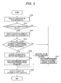
- Fig. 3 is a flow chart that illustrates an example of processing carried out by the controller 32 of the control device 3.
- the controller 32 repeatedly carries out the processing shown in the flow chart for each predetermined control cycle (for example, 100 ms).
- the controller 32 identifies the gear state of the transmission 103 selected by the operation of the shift lever 124 based on the detection signal of the shift position sensor 303 (step S100), and determines whether or not the gear stage is equal to or greater than a predetermined value (the fifth speed in the present embodiment) (step S101).
- the controller 32 detects the rotational speed of the output shaft 101a of the engine 101 (step S102) based on the detection signal of the engine rotational speed sensor 301, and determines whether or not the rotational speed of the output shaft 101a is in a range of a rotational speed for performing the abnormal sound countermeasure control (step S103). As a consequence of the determination, when the rotational speed of the output shaft 101a is in the range of the rotational speed for performing the abnormal sound countermeasure control (step S103: Yes), the abnormal sound countermeasure control (steps S104 and S105) is performed.
- the abnormal sound countermeasure control when the gear stage is the fifth speed, the abnormal sound countermeasure control is performed when the rotational speed of the engine 101 is equal to or less than r 12 (2000 rpm), and when the gear stage is the sixth speed, the abnormal sound countermeasure control is performed when the rotational speed of the engine 101 is equal to or less than r 22 (2500 rpm).
- step S103 When the abnormal sound countermeasure control is performed (step S103: Yes), the controller 32 acquires the driving force that is output from the engine 101 (step S104), and calculates the abnormal sound reduction torque td with reference to the torque map stored in the storage 31, based on the rotational speed of the output shaft 101a of the engine 101 detected in step S102 and the driving force output from the engine 101 acquired in step S104 (step S105). Moreover, the controller 32 sets the abnormal sound reduction torque td to the command torque tc, outputs the same to the electric current output circuit 33 (step S106), and finishes the processing.
- the controller 32 obtains the command torque tc by the normal control function (step S107), outputs the command torque tc to the electric current output circuit 33 (step S106), and finishes the processing.
- the command torque tc is set to a value capable of reducing the abnormal sound. Since the command torque tc of this case is set depending on the driving force that is output from the engine 101, unnecessary torque is not transmitted to the rear wheels 105, and it is possible to suppress the deterioration of the fuel efficiency while suppressing the generation of the abnormal sound.
- the abnormal sound reduction torque td is obtained with reference to the three-dimensional torque map indicating the relationship information showing the relationship between the driving force of the engine 101, the number of revolutions of the engine 101, and the abnormal sound reduction torque td.
- the abnormal sound reduction torque td is obtained with reference to a two-dimensional torque map indicating the relationship information showing the relationship between the driving force of the engine 101 and the abnormal sound reduction torque td.
- the sequence of the processing carried out by the controller 32 in the present embodiment is the same as that of the first embodiment described with reference to the flow chart of Fig. 3 .
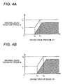
- Figs. 4A and 4B illustrate examples of torque maps according to the present embodiment
- Fig. 4A illustrates a torque map of a case where the selected gear stage is the fifth speed
- Fig. 4B illustrates a torque map of a case where the selected gear stage is the sixth speed.
- the abnormal sound countermeasure control is performed when the number of revolutions of the engine 101 is, for example, 2000 rpm, and the abnormal sound reduction torque td is obtained based on the driving force of the engine 101.
- the abnormal sound reduction torque td is t 11
- the abnormal sound reduction torque td is simply increased from t 11 to t 12 (t 12 > t 11 ) along with an increase of the driving force of the engine 101.
- the abnormal sound reduction torque td is constantly t 12 .
- the abnormal sound countermeasure control is performed when the number of revolutions of the engine 101 is, for example, 2500 rpm.
- the abnormal sound reduction torque td is t 21
- the abnormal sound reduction torque td is simply increased from t 21 to t 22 (t 22 > t 21 ) along with an increase of the driving force of the engine 101.
- the abnormal sound reduction torque td is constantly t 22 .
- t 21 is greater than t 11 and t 22 is greater than t 12 .
- d 21 is greater than d 11 and d 22 is greater than d 12 .
- an oblique line portion shown in each of Figs. 4A and 4B indicates a region where the abnormal sound is generated in the driving force transmission system 110.
- the torque map is set so as to exceed the region. That is, the abnormal sound reduction torque td is set to a value capable of reducing the abnormal sound of the driving force transmission system 110.
- the abnormal sound countermeasure control is performed when the gear stage is the fifth speed or the sixth speed
- the abnormal sound countermeasure control may be performed when the gear stage is the fourth speed to the sixth speed or the third speed to the sixth speed without being limited thereto.
- the number of the gear stage of the transmission 103 may be four or five.
- the abnormal sound reduction torque td is increased as much as the driving force of the engine 101 is great to suppress the occurrence of the abnormal sound.
- the value of the abnormal sound reduction torque td can be suitably set based on the test or the like depending on properties of the four-wheel-drive vehicle 100, without being limited thereto.
- the abnormal sound reduction torque td may be decreased as much as the driving force of the engine 101 is great to suppress the occurrence of the abnormal sound.
- the abnormal sound reduction torque td when the driving force of the engine 101 is in a predetermined range, the abnormal sound reduction torque td is increased as much as the driving force of the engine 101 is great, and when the driving force is in another predetermined range, the abnormal sound reduction torque td may be decreased as much as the driving force of the engine 101 is great.
- the present invention can also be applied to a four-wheel-drive vehicle in which the front wheels 104 are the auxiliary drive wheels, and the rear wheels 105 are the main drive wheels, without being limited thereto.
Landscapes
- Engineering & Computer Science (AREA)
- Chemical & Material Sciences (AREA)
- Combustion & Propulsion (AREA)
- Transportation (AREA)
- Mechanical Engineering (AREA)
- Arrangement And Driving Of Transmission Devices (AREA)
Claims (3)
- Vierradgetriebenes Fahrzeug (100) mit:einer Maschine (103), die konfiguriert ist, eine Antriebskraft für das Fahrzeug (100) zu erzeugen;einer Übertragungsvorrichtung (103), die konfiguriert ist, durch Übertragungsverhältnisse einer Mehrzahl von Stufen eine Drehung einer Antriebswelle (101a) der Maschine (103) umzuschalten;einem Antriebskraftübertragungssystem (110), das in der Lage ist, einen Abtrieb der Übertragungsvorrichtung (103) zu Hauptantriebsrädern zu übertragen, die entweder Vorderräder (104) oder Hinterräder (105) sind, und zu Hilfsantriebsrädern, welche das jeweils andere aus Vorderrädern (104) und Hinterrädern (105) sind;einer Steuervorrichtung (3), die konfiguriert ist, einen Momentwert einzustellen, der zu den Hilfsantriebsrädern zu übertragen ist; undeiner Antriebskraftübertragungsvorrichtung (2), die konfiguriert ist, eine Antriebskraft abhängig von dem durch die Steuervorrichtung (3) eingestellten Wert zu den Hilfsantriebsrädern zu übertragen,dadurch gekennzeichnet, dassdie Steuervorrichtung (3) konfiguriert ist, wenn eine Drehzahl der Abtriebswelle (101a) der Maschine (101) sich einen Bereich befindet, in dem aufgrund einer Schwankung der Antriebskraft ein abnormales Geräusch des Antriebskraftübertragungssystems (110) erzeugt werden kann, wenn nämlich die Drehzahl der Abtriebswelle (101a) der Maschine (101) niedriger als ein vorbestimmter Wert ist, den zu den Hilfsantriebsrädern zu übertragenden Momentwert auf einen Wert einzustellen, der in der Lage ist, das abnormale Geräusch abhängig von der Antriebskraft der Maschine (101) zu reduzieren.
- Vierradgetriebenes Fahrzeug (100) nach Anspruch 1,
wobei die Steuervorrichtung (3) Verhältnisinformation speichert, die ein Verhältnis zwischen der Antriebskraft der Maschine (101) und einem Wert anzeigt, der in der Lage ist, ein abnormales Geräusch für zumindest zwei der Übertragungsverhältnisse der Mehrzahl der Stufen zu reduzieren, und den Momentwert mit Bezug auf die Verhältnisinformationen entsprechend dem Übertragungsverhältnis der Übertragungsvorrichtung (103) während des Fahrens einstellt. - Vierradangetriebenes Fahrzeug (100) nach Anspruch 2,
wobei die Verhältnisinformation eine Information ist, die ein Verhältnis zwischen der Drehzahl der Abtriebswelle (101a) der Maschine (101), der Antriebskraft der Maschine (101) und dem Wert ist, der in der Lage ist, das abnormale Geräusch zu reduzieren.
Applications Claiming Priority (1)
| Application Number | Priority Date | Filing Date | Title |
|---|---|---|---|
| JP2011168202A JP5833857B2 (ja) | 2011-08-01 | 2011-08-01 | 駆動力配分制御装置及び四輪駆動車 |
Publications (2)
| Publication Number | Publication Date |
|---|---|
| EP2554422A1 EP2554422A1 (de) | 2013-02-06 |
| EP2554422B1 true EP2554422B1 (de) | 2015-02-25 |
Family
ID=46982383
Family Applications (1)
| Application Number | Title | Priority Date | Filing Date |
|---|---|---|---|
| EP12178802.0A Not-in-force EP2554422B1 (de) | 2011-08-01 | 2012-08-01 | Vorrichtung zur Steuerung der Antriebskraftverteilung und Fahrzeug mit Vierradantrieb |
Country Status (4)
| Country | Link |
|---|---|
| US (1) | US8909448B2 (de) |
| EP (1) | EP2554422B1 (de) |
| JP (1) | JP5833857B2 (de) |
| CN (1) | CN102910170B (de) |
Families Citing this family (25)
| Publication number | Priority date | Publication date | Assignee | Title |
|---|---|---|---|---|
| US9193347B2 (en) * | 2013-08-15 | 2015-11-24 | GM Global Technology Operations LLC | Method and apparatus for controlling a multi-mode powertrain system to avoid an operating region |
| JP6268527B2 (ja) * | 2014-03-17 | 2018-01-31 | スズキ株式会社 | 車両 |
| JP6217931B2 (ja) | 2014-07-23 | 2017-10-25 | マツダ株式会社 | 四輪駆動車の駆動トルク配分制御装置 |
| JP6064972B2 (ja) * | 2014-10-16 | 2017-01-25 | トヨタ自動車株式会社 | 車両用4輪駆動装置の制御装置 |
| DE102014016451B3 (de) * | 2014-11-06 | 2016-03-24 | Audi Ag | Verfahren zum Betreiben eines Mehrachsantriebsstrangs für ein Kraftfahrzeug sowie entsprechender Mehrachsantriebsstrang |
| JP6007997B2 (ja) * | 2015-01-27 | 2016-10-19 | マツダ株式会社 | 四輪駆動車の制御装置及び四輪駆動車 |
| JP6007998B2 (ja) * | 2015-01-27 | 2016-10-19 | マツダ株式会社 | 四輪駆動車の制御装置及び四輪駆動車 |
| CN105818677B (zh) * | 2015-01-27 | 2018-08-28 | 马自达汽车株式会社 | 四轮驱动车的控制装置 |
| JP6007995B2 (ja) * | 2015-01-27 | 2016-10-19 | マツダ株式会社 | 四輪駆動車の制御装置及び四輪駆動車 |
| JP6264357B2 (ja) * | 2015-01-27 | 2018-01-24 | マツダ株式会社 | 四輪駆動車の制御装置及び四輪駆動車 |
| JP6007999B2 (ja) * | 2015-01-27 | 2016-10-19 | マツダ株式会社 | 四輪駆動車の制御装置及び四輪駆動車 |
| US10001205B2 (en) * | 2015-01-27 | 2018-06-19 | Mazda Motor Corporation | Control apparatus of four-wheel drive vehicle |
| US10023197B2 (en) * | 2015-01-27 | 2018-07-17 | Mazda Motor Corporation | Control device for four-wheel drive vehicle |
| JP6008004B2 (ja) * | 2015-02-27 | 2016-10-19 | マツダ株式会社 | 四輪駆動車の制御装置 |
| JP6056889B2 (ja) * | 2015-02-27 | 2017-01-11 | マツダ株式会社 | 四輪駆動車の制御装置 |
| JP6036878B2 (ja) * | 2015-02-27 | 2016-11-30 | マツダ株式会社 | 四輪駆動車の制御装置 |
| JP6056890B2 (ja) * | 2015-02-27 | 2017-01-11 | マツダ株式会社 | 四輪駆動車の制御装置 |
| JP6056891B2 (ja) * | 2015-02-27 | 2017-01-11 | マツダ株式会社 | 四輪駆動車の制御装置 |
| CN109774783B (zh) * | 2017-11-10 | 2022-05-13 | 现代自动车株式会社 | 用于电动转向的控制方法和控制系统 |
| CN111791716B (zh) * | 2019-04-08 | 2021-12-03 | 华为技术有限公司 | 车辆扭矩处理方法、装置、车辆控制器及车辆 |
| JP6933688B2 (ja) * | 2019-07-09 | 2021-09-08 | 本田技研工業株式会社 | 車両制御装置、車両及び車両制御方法 |
| CN112815090A (zh) * | 2019-11-15 | 2021-05-18 | 本田技研工业株式会社 | 车辆控制装置、车辆和车辆控制方法 |
| KR102895259B1 (ko) * | 2020-10-12 | 2025-12-03 | 현대자동차주식회사 | 차량의 구동력 제어 방법 |
| JP2022100163A (ja) * | 2020-12-23 | 2022-07-05 | トヨタ自動車株式会社 | 音源推定サーバ、音源推定システム、音源推定装置、音源推定方法 |
| DE102022103270A1 (de) | 2022-02-11 | 2023-08-17 | Bayerische Motoren Werke Aktiengesellschaft | Verfahren und Assistenzsystem zur automatischen Geräuschoptimierung und Kraftfahrzeug |
Family Cites Families (10)
| Publication number | Priority date | Publication date | Assignee | Title |
|---|---|---|---|---|
| DE4015701C2 (de) * | 1989-05-26 | 2000-12-14 | Volkswagen Ag | Antriebssystem für ein Fahrzeug |
| JP3157244B2 (ja) | 1992-02-06 | 2001-04-16 | マツダ株式会社 | 車両の差動制限装置 |
| JPH09193680A (ja) * | 1996-01-17 | 1997-07-29 | Honda Motor Co Ltd | 四輪駆動車両における駆動力制御方法 |
| JP3858472B2 (ja) * | 1998-09-07 | 2006-12-13 | トヨタ自動車株式会社 | 車両用駆動装置 |
| JP3622627B2 (ja) * | 2000-03-29 | 2005-02-23 | 豊田工機株式会社 | 駆動力配分制御装置 |
| JP2004306802A (ja) | 2003-04-08 | 2004-11-04 | Toyota Motor Corp | 車両用駆動力配分装置の制御装置 |
| JP4197013B2 (ja) * | 2006-06-28 | 2008-12-17 | トヨタ自動車株式会社 | ハイブリッド車両の制御装置 |
| JP4973222B2 (ja) * | 2007-02-14 | 2012-07-11 | トヨタ自動車株式会社 | 四輪駆動車両の駆動力制御装置 |
| JP5038837B2 (ja) * | 2007-10-01 | 2012-10-03 | 富士重工業株式会社 | 車両のタックイン防止制御装置 |
| JP4846003B2 (ja) * | 2009-08-05 | 2011-12-28 | 本田技研工業株式会社 | 四輪駆動車両のトルク配分制御装置 |
-
2011
- 2011-08-01 JP JP2011168202A patent/JP5833857B2/ja active Active
-
2012
- 2012-08-01 EP EP12178802.0A patent/EP2554422B1/de not_active Not-in-force
- 2012-08-01 US US13/564,311 patent/US8909448B2/en active Active
- 2012-08-01 CN CN201210272530.2A patent/CN102910170B/zh active Active
Also Published As
| Publication number | Publication date |
|---|---|
| EP2554422A1 (de) | 2013-02-06 |
| CN102910170A (zh) | 2013-02-06 |
| US8909448B2 (en) | 2014-12-09 |
| US20130035832A1 (en) | 2013-02-07 |
| JP5833857B2 (ja) | 2015-12-16 |
| CN102910170B (zh) | 2016-03-09 |
| JP2013032060A (ja) | 2013-02-14 |
Similar Documents
| Publication | Publication Date | Title |
|---|---|---|
| EP2554422B1 (de) | Vorrichtung zur Steuerung der Antriebskraftverteilung und Fahrzeug mit Vierradantrieb | |
| EP2554423B1 (de) | Vorrichtung zur Steuerung der Antriebskraftverteilung und Fahrzeug mit Vierradantrieb | |
| JP5827059B2 (ja) | 路面摩擦係数推定装置、駆動力配分制御装置、及び四輪駆動車 | |
| US8700241B2 (en) | Drive control device for standby four-wheel drive vehicle | |
| JP6380055B2 (ja) | 四輪駆動車の制御装置 | |
| US9020723B2 (en) | Driving force distribution controller and four-wheel drive vehicle | |
| JP5476473B2 (ja) | 車両のスキッド検知装置 | |
| JP6216666B2 (ja) | 駆動力配分制御装置 | |
| US11186284B2 (en) | Control device | |
| US20210009106A1 (en) | Hybrid drivetrain for a hybrid-driven vehicle and method for same | |
| EP3916269B1 (de) | Fahrzeugantriebsvorrichtung und hybridfahrzeug | |
| JP2021020535A (ja) | 車両の駆動制御装置 | |
| EP2930053B1 (de) | Fahrzeugsteuerungsvorrichtung | |
| JP4165344B2 (ja) | 車両の制御装置 | |
| JP5772703B2 (ja) | 車両動力装置の制御装置 | |
| JP2011230712A (ja) | 車両の制御装置 | |
| JP6256180B2 (ja) | 制御装置 |
Legal Events
| Date | Code | Title | Description |
|---|---|---|---|
| PUAI | Public reference made under article 153(3) epc to a published international application that has entered the european phase |
Free format text: ORIGINAL CODE: 0009012 |
|
| AK | Designated contracting states |
Kind code of ref document: A1 Designated state(s): AL AT BE BG CH CY CZ DE DK EE ES FI FR GB GR HR HU IE IS IT LI LT LU LV MC MK MT NL NO PL PT RO RS SE SI SK SM TR |
|
| AX | Request for extension of the european patent |
Extension state: BA ME |
|
| 17P | Request for examination filed |
Effective date: 20130801 |
|
| RBV | Designated contracting states (corrected) |
Designated state(s): AL AT BE BG CH CY CZ DE DK EE ES FI FR GB GR HR HU IE IS IT LI LT LU LV MC MK MT NL NO PL PT RO RS SE SI SK SM TR |
|
| 17Q | First examination report despatched |
Effective date: 20131014 |
|
| RIC1 | Information provided on ipc code assigned before grant |
Ipc: B60K 17/35 20060101ALI20140627BHEP Ipc: B60K 23/08 20060101AFI20140627BHEP |
|
| GRAP | Despatch of communication of intention to grant a patent |
Free format text: ORIGINAL CODE: EPIDOSNIGR1 |
|
| INTG | Intention to grant announced |
Effective date: 20140916 |
|
| RIN1 | Information on inventor provided before grant (corrected) |
Inventor name: YAGI, YASUSHI Inventor name: NOZU, TOMOHIRO Inventor name: TATARA, AKIHIRO Inventor name: SHIGETA, RYOHEI Inventor name: KOFU, DAISUKE |
|
| GRAS | Grant fee paid |
Free format text: ORIGINAL CODE: EPIDOSNIGR3 |
|
| GRAA | (expected) grant |
Free format text: ORIGINAL CODE: 0009210 |
|
| AK | Designated contracting states |
Kind code of ref document: B1 Designated state(s): AL AT BE BG CH CY CZ DE DK EE ES FI FR GB GR HR HU IE IS IT LI LT LU LV MC MK MT NL NO PL PT RO RS SE SI SK SM TR |
|
| REG | Reference to a national code |
Ref country code: GB Ref legal event code: FG4D |
|
| REG | Reference to a national code |
Ref country code: CH Ref legal event code: EP |
|
| REG | Reference to a national code |
Ref country code: IE Ref legal event code: FG4D |
|
| REG | Reference to a national code |
Ref country code: DE Ref legal event code: R096 Ref document number: 602012005398 Country of ref document: DE Effective date: 20150409 |
|
| REG | Reference to a national code |
Ref country code: AT Ref legal event code: REF Ref document number: 711642 Country of ref document: AT Kind code of ref document: T Effective date: 20150415 |
|
| REG | Reference to a national code |
Ref country code: NL Ref legal event code: VDEP Effective date: 20150225 |
|
| REG | Reference to a national code |
Ref country code: AT Ref legal event code: MK05 Ref document number: 711642 Country of ref document: AT Kind code of ref document: T Effective date: 20150225 |
|
| REG | Reference to a national code |
Ref country code: LT Ref legal event code: MG4D |
|
| PG25 | Lapsed in a contracting state [announced via postgrant information from national office to epo] |
Ref country code: ES Free format text: LAPSE BECAUSE OF FAILURE TO SUBMIT A TRANSLATION OF THE DESCRIPTION OR TO PAY THE FEE WITHIN THE PRESCRIBED TIME-LIMIT Effective date: 20150225 Ref country code: NO Free format text: LAPSE BECAUSE OF FAILURE TO SUBMIT A TRANSLATION OF THE DESCRIPTION OR TO PAY THE FEE WITHIN THE PRESCRIBED TIME-LIMIT Effective date: 20150525 Ref country code: FI Free format text: LAPSE BECAUSE OF FAILURE TO SUBMIT A TRANSLATION OF THE DESCRIPTION OR TO PAY THE FEE WITHIN THE PRESCRIBED TIME-LIMIT Effective date: 20150225 Ref country code: LT Free format text: LAPSE BECAUSE OF FAILURE TO SUBMIT A TRANSLATION OF THE DESCRIPTION OR TO PAY THE FEE WITHIN THE PRESCRIBED TIME-LIMIT Effective date: 20150225 Ref country code: SE Free format text: LAPSE BECAUSE OF FAILURE TO SUBMIT A TRANSLATION OF THE DESCRIPTION OR TO PAY THE FEE WITHIN THE PRESCRIBED TIME-LIMIT Effective date: 20150225 Ref country code: HR Free format text: LAPSE BECAUSE OF FAILURE TO SUBMIT A TRANSLATION OF THE DESCRIPTION OR TO PAY THE FEE WITHIN THE PRESCRIBED TIME-LIMIT Effective date: 20150225 |
|
| PG25 | Lapsed in a contracting state [announced via postgrant information from national office to epo] |
Ref country code: LV Free format text: LAPSE BECAUSE OF FAILURE TO SUBMIT A TRANSLATION OF THE DESCRIPTION OR TO PAY THE FEE WITHIN THE PRESCRIBED TIME-LIMIT Effective date: 20150225 Ref country code: AT Free format text: LAPSE BECAUSE OF FAILURE TO SUBMIT A TRANSLATION OF THE DESCRIPTION OR TO PAY THE FEE WITHIN THE PRESCRIBED TIME-LIMIT Effective date: 20150225 Ref country code: IS Free format text: LAPSE BECAUSE OF FAILURE TO SUBMIT A TRANSLATION OF THE DESCRIPTION OR TO PAY THE FEE WITHIN THE PRESCRIBED TIME-LIMIT Effective date: 20150625 Ref country code: RS Free format text: LAPSE BECAUSE OF FAILURE TO SUBMIT A TRANSLATION OF THE DESCRIPTION OR TO PAY THE FEE WITHIN THE PRESCRIBED TIME-LIMIT Effective date: 20150225 Ref country code: GR Free format text: LAPSE BECAUSE OF FAILURE TO SUBMIT A TRANSLATION OF THE DESCRIPTION OR TO PAY THE FEE WITHIN THE PRESCRIBED TIME-LIMIT Effective date: 20150526 |
|
| PG25 | Lapsed in a contracting state [announced via postgrant information from national office to epo] |
Ref country code: NL Free format text: LAPSE BECAUSE OF FAILURE TO SUBMIT A TRANSLATION OF THE DESCRIPTION OR TO PAY THE FEE WITHIN THE PRESCRIBED TIME-LIMIT Effective date: 20150225 |
|
| PG25 | Lapsed in a contracting state [announced via postgrant information from national office to epo] |
Ref country code: CZ Free format text: LAPSE BECAUSE OF FAILURE TO SUBMIT A TRANSLATION OF THE DESCRIPTION OR TO PAY THE FEE WITHIN THE PRESCRIBED TIME-LIMIT Effective date: 20150225 Ref country code: DK Free format text: LAPSE BECAUSE OF FAILURE TO SUBMIT A TRANSLATION OF THE DESCRIPTION OR TO PAY THE FEE WITHIN THE PRESCRIBED TIME-LIMIT Effective date: 20150225 Ref country code: EE Free format text: LAPSE BECAUSE OF FAILURE TO SUBMIT A TRANSLATION OF THE DESCRIPTION OR TO PAY THE FEE WITHIN THE PRESCRIBED TIME-LIMIT Effective date: 20150225 Ref country code: SK Free format text: LAPSE BECAUSE OF FAILURE TO SUBMIT A TRANSLATION OF THE DESCRIPTION OR TO PAY THE FEE WITHIN THE PRESCRIBED TIME-LIMIT Effective date: 20150225 Ref country code: RO Free format text: LAPSE BECAUSE OF FAILURE TO SUBMIT A TRANSLATION OF THE DESCRIPTION OR TO PAY THE FEE WITHIN THE PRESCRIBED TIME-LIMIT Effective date: 20150225 |
|
| REG | Reference to a national code |
Ref country code: DE Ref legal event code: R097 Ref document number: 602012005398 Country of ref document: DE |
|
| PG25 | Lapsed in a contracting state [announced via postgrant information from national office to epo] |
Ref country code: PL Free format text: LAPSE BECAUSE OF FAILURE TO SUBMIT A TRANSLATION OF THE DESCRIPTION OR TO PAY THE FEE WITHIN THE PRESCRIBED TIME-LIMIT Effective date: 20150225 |
|
| PG25 | Lapsed in a contracting state [announced via postgrant information from national office to epo] |
Ref country code: IT Free format text: LAPSE BECAUSE OF FAILURE TO SUBMIT A TRANSLATION OF THE DESCRIPTION OR TO PAY THE FEE WITHIN THE PRESCRIBED TIME-LIMIT Effective date: 20150225 |
|
| PLBE | No opposition filed within time limit |
Free format text: ORIGINAL CODE: 0009261 |
|
| STAA | Information on the status of an ep patent application or granted ep patent |
Free format text: STATUS: NO OPPOSITION FILED WITHIN TIME LIMIT |
|
| 26N | No opposition filed |
Effective date: 20151126 |
|
| PG25 | Lapsed in a contracting state [announced via postgrant information from national office to epo] |
Ref country code: SI Free format text: LAPSE BECAUSE OF FAILURE TO SUBMIT A TRANSLATION OF THE DESCRIPTION OR TO PAY THE FEE WITHIN THE PRESCRIBED TIME-LIMIT Effective date: 20150225 |
|
| PG25 | Lapsed in a contracting state [announced via postgrant information from national office to epo] |
Ref country code: LU Free format text: LAPSE BECAUSE OF FAILURE TO SUBMIT A TRANSLATION OF THE DESCRIPTION OR TO PAY THE FEE WITHIN THE PRESCRIBED TIME-LIMIT Effective date: 20150801 Ref country code: MC Free format text: LAPSE BECAUSE OF FAILURE TO SUBMIT A TRANSLATION OF THE DESCRIPTION OR TO PAY THE FEE WITHIN THE PRESCRIBED TIME-LIMIT Effective date: 20150225 |
|
| REG | Reference to a national code |
Ref country code: CH Ref legal event code: PL |
|
| PG25 | Lapsed in a contracting state [announced via postgrant information from national office to epo] |
Ref country code: CH Free format text: LAPSE BECAUSE OF NON-PAYMENT OF DUE FEES Effective date: 20150831 Ref country code: LI Free format text: LAPSE BECAUSE OF NON-PAYMENT OF DUE FEES Effective date: 20150831 |
|
| PG25 | Lapsed in a contracting state [announced via postgrant information from national office to epo] |
Ref country code: BE Free format text: LAPSE BECAUSE OF FAILURE TO SUBMIT A TRANSLATION OF THE DESCRIPTION OR TO PAY THE FEE WITHIN THE PRESCRIBED TIME-LIMIT Effective date: 20150225 |
|
| REG | Reference to a national code |
Ref country code: IE Ref legal event code: MM4A |
|
| REG | Reference to a national code |
Ref country code: FR Ref legal event code: ST Effective date: 20160429 |
|
| PG25 | Lapsed in a contracting state [announced via postgrant information from national office to epo] |
Ref country code: IE Free format text: LAPSE BECAUSE OF NON-PAYMENT OF DUE FEES Effective date: 20150801 |
|
| PG25 | Lapsed in a contracting state [announced via postgrant information from national office to epo] |
Ref country code: FR Free format text: LAPSE BECAUSE OF NON-PAYMENT OF DUE FEES Effective date: 20150831 |
|
| PG25 | Lapsed in a contracting state [announced via postgrant information from national office to epo] |
Ref country code: MT Free format text: LAPSE BECAUSE OF FAILURE TO SUBMIT A TRANSLATION OF THE DESCRIPTION OR TO PAY THE FEE WITHIN THE PRESCRIBED TIME-LIMIT Effective date: 20150225 |
|
| GBPC | Gb: european patent ceased through non-payment of renewal fee |
Effective date: 20160801 |
|
| PG25 | Lapsed in a contracting state [announced via postgrant information from national office to epo] |
Ref country code: BG Free format text: LAPSE BECAUSE OF FAILURE TO SUBMIT A TRANSLATION OF THE DESCRIPTION OR TO PAY THE FEE WITHIN THE PRESCRIBED TIME-LIMIT Effective date: 20150225 Ref country code: HU Free format text: LAPSE BECAUSE OF FAILURE TO SUBMIT A TRANSLATION OF THE DESCRIPTION OR TO PAY THE FEE WITHIN THE PRESCRIBED TIME-LIMIT; INVALID AB INITIO Effective date: 20120801 Ref country code: SM Free format text: LAPSE BECAUSE OF FAILURE TO SUBMIT A TRANSLATION OF THE DESCRIPTION OR TO PAY THE FEE WITHIN THE PRESCRIBED TIME-LIMIT Effective date: 20150225 |
|
| PG25 | Lapsed in a contracting state [announced via postgrant information from national office to epo] |
Ref country code: CY Free format text: LAPSE BECAUSE OF FAILURE TO SUBMIT A TRANSLATION OF THE DESCRIPTION OR TO PAY THE FEE WITHIN THE PRESCRIBED TIME-LIMIT Effective date: 20150225 |
|
| PG25 | Lapsed in a contracting state [announced via postgrant information from national office to epo] |
Ref country code: GB Free format text: LAPSE BECAUSE OF NON-PAYMENT OF DUE FEES Effective date: 20160801 |
|
| PG25 | Lapsed in a contracting state [announced via postgrant information from national office to epo] |
Ref country code: TR Free format text: LAPSE BECAUSE OF FAILURE TO SUBMIT A TRANSLATION OF THE DESCRIPTION OR TO PAY THE FEE WITHIN THE PRESCRIBED TIME-LIMIT Effective date: 20150225 |
|
| PG25 | Lapsed in a contracting state [announced via postgrant information from national office to epo] |
Ref country code: PT Free format text: LAPSE BECAUSE OF FAILURE TO SUBMIT A TRANSLATION OF THE DESCRIPTION OR TO PAY THE FEE WITHIN THE PRESCRIBED TIME-LIMIT Effective date: 20150225 Ref country code: MK Free format text: LAPSE BECAUSE OF FAILURE TO SUBMIT A TRANSLATION OF THE DESCRIPTION OR TO PAY THE FEE WITHIN THE PRESCRIBED TIME-LIMIT Effective date: 20150225 |
|
| PG25 | Lapsed in a contracting state [announced via postgrant information from national office to epo] |
Ref country code: AL Free format text: LAPSE BECAUSE OF FAILURE TO SUBMIT A TRANSLATION OF THE DESCRIPTION OR TO PAY THE FEE WITHIN THE PRESCRIBED TIME-LIMIT Effective date: 20150225 |
|
| PGFP | Annual fee paid to national office [announced via postgrant information from national office to epo] |
Ref country code: DE Payment date: 20200722 Year of fee payment: 9 |
|
| REG | Reference to a national code |
Ref country code: DE Ref legal event code: R119 Ref document number: 602012005398 Country of ref document: DE |
|
| PG25 | Lapsed in a contracting state [announced via postgrant information from national office to epo] |
Ref country code: DE Free format text: LAPSE BECAUSE OF NON-PAYMENT OF DUE FEES Effective date: 20220301 |