EP2552546B1 - Office-based system for treating uterine fibroids or other tissues with hifu - Google Patents
Office-based system for treating uterine fibroids or other tissues with hifu Download PDFInfo
- Publication number
- EP2552546B1 EP2552546B1 EP11763567.2A EP11763567A EP2552546B1 EP 2552546 B1 EP2552546 B1 EP 2552546B1 EP 11763567 A EP11763567 A EP 11763567A EP 2552546 B1 EP2552546 B1 EP 2552546B1
- Authority
- EP
- European Patent Office
- Prior art keywords
- hifu
- treatment
- volume
- tissue
- elemental
- Prior art date
- Legal status (The legal status is an assumption and is not a legal conclusion. Google has not performed a legal analysis and makes no representation as to the accuracy of the status listed.)
- Not-in-force
Links
Images


Classifications
-
- A—HUMAN NECESSITIES
- A61—MEDICAL OR VETERINARY SCIENCE; HYGIENE
- A61N—ELECTROTHERAPY; MAGNETOTHERAPY; RADIATION THERAPY; ULTRASOUND THERAPY
- A61N7/00—Ultrasound therapy
- A61N7/02—Localised ultrasound hyperthermia
-
- A—HUMAN NECESSITIES
- A61—MEDICAL OR VETERINARY SCIENCE; HYGIENE
- A61N—ELECTROTHERAPY; MAGNETOTHERAPY; RADIATION THERAPY; ULTRASOUND THERAPY
- A61N7/00—Ultrasound therapy
-
- A—HUMAN NECESSITIES
- A61—MEDICAL OR VETERINARY SCIENCE; HYGIENE
- A61B—DIAGNOSIS; SURGERY; IDENTIFICATION
- A61B18/00—Surgical instruments, devices or methods for transferring non-mechanical forms of energy to or from the body
-
- A—HUMAN NECESSITIES
- A61—MEDICAL OR VETERINARY SCIENCE; HYGIENE
- A61B—DIAGNOSIS; SURGERY; IDENTIFICATION
- A61B8/00—Diagnosis using ultrasonic, sonic or infrasonic waves
- A61B8/08—Detecting organic movements or changes, e.g. tumours, cysts, swellings
-
- A—HUMAN NECESSITIES
- A61—MEDICAL OR VETERINARY SCIENCE; HYGIENE
- A61N—ELECTROTHERAPY; MAGNETOTHERAPY; RADIATION THERAPY; ULTRASOUND THERAPY
- A61N7/00—Ultrasound therapy
- A61N7/02—Localised ultrasound hyperthermia
- A61N7/022—Localised ultrasound hyperthermia intracavitary
-
- G—PHYSICS
- G16—INFORMATION AND COMMUNICATION TECHNOLOGY [ICT] SPECIALLY ADAPTED FOR SPECIFIC APPLICATION FIELDS
- G16H—HEALTHCARE INFORMATICS, i.e. INFORMATION AND COMMUNICATION TECHNOLOGY [ICT] SPECIALLY ADAPTED FOR THE HANDLING OR PROCESSING OF MEDICAL OR HEALTHCARE DATA
- G16H40/00—ICT specially adapted for the management or administration of healthcare resources or facilities; ICT specially adapted for the management or operation of medical equipment or devices
- G16H40/60—ICT specially adapted for the management or administration of healthcare resources or facilities; ICT specially adapted for the management or operation of medical equipment or devices for the operation of medical equipment or devices
- G16H40/63—ICT specially adapted for the management or administration of healthcare resources or facilities; ICT specially adapted for the management or operation of medical equipment or devices for the operation of medical equipment or devices for local operation
-
- A—HUMAN NECESSITIES
- A61—MEDICAL OR VETERINARY SCIENCE; HYGIENE
- A61B—DIAGNOSIS; SURGERY; IDENTIFICATION
- A61B17/00—Surgical instruments, devices or methods, e.g. tourniquets
- A61B2017/00017—Electrical control of surgical instruments
- A61B2017/00137—Details of operation mode
- A61B2017/00154—Details of operation mode pulsed
- A61B2017/00172—Pulse trains, bursts, intermittent continuous operation
-
- A—HUMAN NECESSITIES
- A61—MEDICAL OR VETERINARY SCIENCE; HYGIENE
- A61B—DIAGNOSIS; SURGERY; IDENTIFICATION
- A61B90/00—Instruments, implements or accessories specially adapted for surgery or diagnosis and not covered by any of the groups A61B1/00 - A61B50/00, e.g. for luxation treatment or for protecting wound edges
- A61B90/36—Image-producing devices or illumination devices not otherwise provided for
- A61B90/37—Surgical systems with images on a monitor during operation
- A61B2090/378—Surgical systems with images on a monitor during operation using ultrasound
-
- A—HUMAN NECESSITIES
- A61—MEDICAL OR VETERINARY SCIENCE; HYGIENE
- A61N—ELECTROTHERAPY; MAGNETOTHERAPY; RADIATION THERAPY; ULTRASOUND THERAPY
- A61N7/00—Ultrasound therapy
- A61N2007/0004—Applications of ultrasound therapy
-
- A—HUMAN NECESSITIES
- A61—MEDICAL OR VETERINARY SCIENCE; HYGIENE
- A61N—ELECTROTHERAPY; MAGNETOTHERAPY; RADIATION THERAPY; ULTRASOUND THERAPY
- A61N7/00—Ultrasound therapy
- A61N2007/0043—Ultrasound therapy intra-cavitary
-
- A—HUMAN NECESSITIES
- A61—MEDICAL OR VETERINARY SCIENCE; HYGIENE
- A61N—ELECTROTHERAPY; MAGNETOTHERAPY; RADIATION THERAPY; ULTRASOUND THERAPY
- A61N7/00—Ultrasound therapy
- A61N2007/0056—Beam shaping elements
- A61N2007/0065—Concave transducers
-
- A—HUMAN NECESSITIES
- A61—MEDICAL OR VETERINARY SCIENCE; HYGIENE
- A61N—ELECTROTHERAPY; MAGNETOTHERAPY; RADIATION THERAPY; ULTRASOUND THERAPY
- A61N7/00—Ultrasound therapy
- A61N2007/0078—Ultrasound therapy with multiple treatment transducers
-
- A—HUMAN NECESSITIES
- A61—MEDICAL OR VETERINARY SCIENCE; HYGIENE
- A61N—ELECTROTHERAPY; MAGNETOTHERAPY; RADIATION THERAPY; ULTRASOUND THERAPY
- A61N7/00—Ultrasound therapy
- A61N2007/0082—Scanning transducers
-
- A—HUMAN NECESSITIES
- A61—MEDICAL OR VETERINARY SCIENCE; HYGIENE
- A61N—ELECTROTHERAPY; MAGNETOTHERAPY; RADIATION THERAPY; ULTRASOUND THERAPY
- A61N7/00—Ultrasound therapy
- A61N2007/0086—Beam steering
- A61N2007/0091—Beam steering with moving parts, e.g. transducers, lenses, reflectors
-
- A—HUMAN NECESSITIES
- A61—MEDICAL OR VETERINARY SCIENCE; HYGIENE
- A61N—ELECTROTHERAPY; MAGNETOTHERAPY; RADIATION THERAPY; ULTRASOUND THERAPY
- A61N7/00—Ultrasound therapy
- A61N2007/0086—Beam steering
- A61N2007/0095—Beam steering by modifying an excitation signal
-
- Y—GENERAL TAGGING OF NEW TECHNOLOGICAL DEVELOPMENTS; GENERAL TAGGING OF CROSS-SECTIONAL TECHNOLOGIES SPANNING OVER SEVERAL SECTIONS OF THE IPC; TECHNICAL SUBJECTS COVERED BY FORMER USPC CROSS-REFERENCE ART COLLECTIONS [XRACs] AND DIGESTS
- Y02—TECHNOLOGIES OR APPLICATIONS FOR MITIGATION OR ADAPTATION AGAINST CLIMATE CHANGE
- Y02A—TECHNOLOGIES FOR ADAPTATION TO CLIMATE CHANGE
- Y02A90/00—Technologies having an indirect contribution to adaptation to climate change
- Y02A90/10—Information and communication technologies [ICT] supporting adaptation to climate change, e.g. for weather forecasting or climate simulation
Definitions
- the technology disclosed herein relates to methods and apparatus for the treatment of internal body tissues and in particular to the treatment of internal body tissues with high intensity focused ultrasound (HIFU).
- HIFU high intensity focused ultrasound
- HIFU high intensity focused ultrasound
- HIFU HIFU
- One of the drawbacks of using HIFU to treat internal body tissues is the time required to treat a given volume of tissue.
- HIFU procedures may take up to 3 hours to treat a single tumor, which has contributed to poor acceptance of these procedures by both physicians and patients.
- the amount of energy required to completely ablate a large volume of tissue results in substantial thermal conduction outward from the ablation volume, which can raise the risk of thermal damage to surrounding healthy tissue.
- US 6 007 499 discloses methods and apparatus for enabling substantially bloodless surgery and for stemming hemorrhaging.
- High intensity focused ultrasound (“HIFU”) is used to form cauterized tissue regions prior to surgical incision, for example, forming a cauterized tissue shell around a tumor to be removed.
- HIFU High intensity focused ultrasound
- US 6 626 855 B1 discloses an ultrasound system used for both imaging and delivery high intensity ultrasound energy therapy to treatment sites and a method for treating tumors and other undesired tissue within a patient's body with an ultrasound device.
- the technology disclosed herein relates to a system for treating uterine fibroids or other tissue that is compact enough to be used in a physician's office.
- the system treats the tissue with energy from an energy source, which includes high intensity focused ultrasound (HIFU).
- energy sources could also include radiofrequency, radiation, microwave, cryotherapy, laser, etc.
- HIFU high intensity focused ultrasound
- the preferred embodiment is HIFU, due to its unique ability to be non-invasively focused deep inside body tissues without the need for punctures or incisions.
- the invention is defined in appended independent claim 1, preferred embodiments are described in the dependent claims.
- a desired target volume of tissue is treated with HIFU by ablating a number of adjacent elemental treatment volumes to form "building blocks" used to treat the full target volume of tissue.
- Each elemental treatment volume is created by directing the focal zone of a HIFU transducer to ablate a sub-volume that is larger than the focal zone itself but smaller than the overall desired treatment volume.
- Each elemental treatment volume is created by repeatedly directing the focal zone of the HIFU transducer over the perimeter of the elemental treatment volume as treatment energy is being applied.
- Treatment signals from the HIFU transducer can be applied to the tissue without using temperature data or feedback control even in the presence of bubbles such that the treatment time is significantly decreased.
- a mechanical or electronic steering apparatus directs the focal zone of a HIFU beam around the perimeter of the elemental treatment volume until the tissue encompassed by the perimeter is ablated.
- a center region of the elemental treatment volume is not directly ablated but is treated by thermal conduction as the perimeter is ablated.
- the disclosed technology includes a HIFU transducer that is configured to deliver treatment energy to a focal zone and a computer controlled beam steerer for repeatedly positioning the focal zone over a perimeter of an elemental treatment volume as treatment energy is applied.
- a pattern of elemental treatment volumes is created to form a shell of ablated tissue surrounding the treatment volume (similar to the geometry of an eggshell surrounding an egg).
- Treating a desired tissue volume using this type of shell ablation has two primary utilities in HIFU therapy: (1)
- the ablated shell interrupts the supply of blood to the interior of the treatment volume, causing the otherwise untreated tissue located within the shell to ischemically necrose in situ. In this manner, the ischemic damage to the center of the volume results in the destruction of the entire volume over time, even though only the outer boundary is directly treated with HIFU.
- the elemental treatment volumes comprising the shell pattern are deposited in such a way that heat conduction toward the interior of the volume results in immediate thermal destruction of the inner tissue, even though only the outer boundary is directly ablated with HIFU energy.
- Both of these utilities provided by shell ablation serve to significantly improve the efficiency of HIFU therapy because they result in an effective tissue treatment volume that is larger than the volume directly ablated with HIFU energy. Leveraging either or both of these shell ablation advantages increases the throughput achieved by a given HIFU procedure.
- a number of elemental treatment volumes are created to fill or partially fill the target treatment volume.
- a HIFU treatment device directs a focal zone of a HIFU transducer to move in a path to surround or envelop a tissue volume.
- the pattern in which the focal zone of the HIFU transducer is moved results in creating a series of ablated tissue toroids of varying diameter that are stacked to surround and envelop the tissue volume.
- the focal zone is moved to create a spiral shell of ablated tissue to envelop the treatment volume.
- one embodiment employs a computer-controlled mechanism to automatically move the HIFU focal zone and apply HIFU energy in such a manner to create the desired elemental treatment volume and/or geometric shell while the user simply holds the applicator stationary.
- the technology disclosed herein relates to a method of treating internal body tissues such as uterine fibroids, benign or malignant tumors, or the like.
- internal body tissues such as uterine fibroids, benign or malignant tumors, or the like.
- the technology can be used to treat a volume of any internal body tissue.
- the desired treatment volume is treated by creating a pattern of one or more elemental treatment volumes in the tissue.
- each type of elemental volume shares the common feature that it is comprised of a volume of ablated tissue that is greater than the volume of the HIFU focal zone due to controlled motion of that focal zone around or along the elemental volume in a prescribed manner.
- the acoustic focal zone referenced herein is commonly defined as the volume encompassed by the -6 dB pressure contour of the acoustic waveform as measured from its spatial maximum. Those skilled in the art will recognize that the dimensions of this -6 dB pressure contour are also referred to as the full-width half-maximum, or FWHM, dimensions.
- a typical focal zone as implemented in the embodiments described herein is ovoid in shape, with FWHM dimensions of approximately 10 mm. in length along the beam axis and 2 mm. in width perpendicular to the beam axis.
- a desired volume of tissue to be treated is exposed to energy that ablates the tissue in a shell-like pattern, which completely or partially surrounds the tissue volume while only directly ablating the outer boundary.
- the tissue encompassed by the shell then remains in the body and necroses in situ due to effects other than direct ablation.
- These other effects causing in situ necrosis may include some combination of:
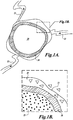
- FIGURE 1A illustrates a tissue volume, such as a uterine fibroid 20, to be treated.
- Uterine fibroids may be irregularly shaped but are often generally spherical or oval shaped.
- the fibroid 20 includes one or more blood vessels 22 that supply the fibroid 20 with blood.
- a 3-dimensional ablated shell 30 is formed inside the periphery of the fibroid 20 in a manner that isolates the fibroid tissue inside the shell from the blood vessels 22 that supply blood to, and take blood from the fibroid 20.
- this interior tissue can be left in the body to ischemically necrose and eventually be absorbed or healed via normal body healing mechanisms over a period of days/weeks.
- an ablated shell 30 is created by exposing the tissue situated in the shell to HIFU energy for a sufficient time or at sufficient power so as to cause direct tissue necrosis.
- HIFU power and energy can generally be used interchangeably, except in those instances where one or the other of these particular quantities is implied by the context in which it is used. This is to be distinguished from secondary ischemic necrosis that occurs in the tissue inside the shell as a result of it being cut off from its blood supply or as a result of other effects listed above.
- the volume of tissue ablated to create the shell is smaller than the overall volume of tissue to be treated, the time required to treat the combined mass of tissue (i.e., shell plus encapsulated volume) is reduced below that which would be required if the entire volume were to be directly ablated.
- ablation refers to the direct necrosis of tissue resulting from the immediate thermal and/or mechanical effects caused by exposure of the tissue to the energy source.
- shell refers to an ablated surface which reduces or eliminates blood flow across that surface.
- the geometry of this surface may be such that it entirely encapsulates a volume (e.g., a sphere) or non-closed such that it only partially encapsulates the volume (e.g., a concave disk).
- encapsulate refers to creation of such surfaces.
- the shell 30 is shown as fitting entirely within volume of the fibroid 20.
- the size of the shell may be varied so that its inner non-ablated region encapsulates the entire fibroid 20.
- the fibroid 20 may have multiple shells created therein.
- one or more partial shells are created which do not entirely encapsulate the tissue site, but reduce or eliminate blood flow to or from its interior across those partial shell(s). This leads to necrosis of at least part of the tissue volume.
- FIGURE 1B illustrates a close-up view of the interior of the fibroid 20 and the ablated shell 30 that surrounds it.
- the fibroid 20 includes an interior region 25 within the ablated shell 30 that will ischemically necrose by virtue of the tissue being cut off from an external blood supply (with some contributions via other secondary injury pathway mechanisms associated with healing, e.g., inflammation, apoptosis, et al.).
- Tissue that forms the ablated shell 30 is directly necrosed via thermal and/or mechanical effects of exposure to the focal zone of the HIFU beam.
- Some fibroid tissue 35 external to the ablated shell 30 may also be partially or completely destroyed via thermal necrosis (due to heat conducted from the ablated shell 30) and/or secondary injury pathway mechanisms (ischemia, inflammation, apoptosis, et al.).
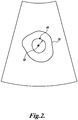
- FIGURE 2 illustrates a 2-dimensional image of a fibroid 20 produced with an ultrasound imaging transducer and other ultrasound imaging components.
- an imaging transducer and HIFU transducer are combined as a single unit.
- an ultrasound imaging transducer, ultrasound image processor and display (all not shown) are used to produce the image of the fibroid 20 for a physician.
- the display may include a crosshair or other marker 38 on the image of the fibroid 20 that indicates a reference point with respect to the focal zone of the HIFU transducer so that a user can aim the HIFU transducer at the tissue volume.
- the physician can interact with the display by, for example, adjusting the radius of a circular marker ring 40 that is centered around the crosshair 38 in order to specify the boundaries of the desired treatment volume or the boundaries of the ablated shell to be created (which may be the same). From the boundaries defined by the size of the marker ring 40, a processing system, such as general or special purpose computer (not shown) computes the size of the ablated shell that should be created to encapsulate the fibroid 20.
- the marker ring 40 may be adjustable to form shapes other than a circle, such as ovals or cones, etc., by, for example, stretching the sides of the marker ring 40 in order to allow the physician to define the shape of the three-dimensional ablated shell.
- the size of the marker ring 40 is adjusted manually by the physician.
- image processing techniques may be used to automatically size the marker ring based on an estimate of the boundaries of the tissue to be treated.
- the boundaries may be further adjusted by the physician if desired.
- the boundaries may be adjusted on a three-dimensional image of the tissue.
- an image processing algorithm may automatically detect the edges of the structure to treat (e.g., boundary detection). In this case, the physician may locate the structure to treat by placing one or many point(s) (crosshairs) inside the structure.
- an image processing algorithm would seek out the boundaries of the structure by (i) identifying local changes in contrast (e.g., speckle brightness) in the ultrasound image (ii) identifying areas of specular backscatter versus backscatter from speckle targets.
- an automatic treatment planning algorithm may be used to determine the number and position of elemental treatment volumes required to yield a fully ablated shell. The physician could walk through the order of the treatment on the ultrasound image prior to HIFU delivery and make any necessary adjustments.
- a computer with the HIFU treatment system begins controlling the position of the focal zone of the HIFU transducer to ablate the tissue to create the shell.
- the target volume may be larger than the ultrasound image available.
- Another possibility that may be encountered is that the range of movement of the therapy beam does not allow the entire target to be treated.
- multiple ultrasound 2D images or 3D volumes may be stitched together to visualize the full extent of the target by manually moving the applicator. This image data may be stored for future reference.
- the algorithm may automatically plan treatment on the stitched images and recommend where the treatment should start.
- the physician may also plan treatment from the stitched image data.
- the physician may move the transducer to a region that enables the therapy transducer to create the initial elemental treatment volumes within the target. Spatial image correlation techniques may be used to assist the physician in appropriate applicator placement with respect to the target.
- Device position sensors e.g., magnetic sensors
- the device position sensors may also be combined with the image correlation techniques for even better accuracy.
- the applicator may be manually moved such that image correlation techniques and/or position sensors are used to assist the physician in applicator placement for the next treatment site. By continuing the process, the full extent of the target may be treated.
- manual movement of the applicator to acquire images to visualize the entire target is not necessary. The data set to see the entire target may be acquired in one applicator position; however, the applicator will have to be moved as previously described due to the movement limitations of the therapy device inside the applicator.
- FIGURES 3A and 3B illustrate one exemplary configuration of a cylindrical elemental treatment volume 80 that is used to build up the full desired treatment volume.
- the elemental treatment volume 80 is created by directing a focal zone 81 of a HIFU beam 83 around the perimeter of the elemental treatment volume.
- the focal zone 81 can be continuously moved around the perimeter of the elemental treatment volume for one or more times while a HIFU transmitter continually transmits HIFU pulses until the perimeter of the elemental treatment volume 80 is sufficiently ablated.
- the focal zone 81 can be moved to discrete positions around the perimeter and the HIFU beam 83 pulsed on and off to fully ablate the different positions around the perimeter of the elemental treatment volume.
- the elemental treatment volume 80 has a center area 79 that is not directly or is minimally exposed to the focal zone 81 of the HIFU beam 83. This center area 79 is indirectly necrosed by heat conduction created as the perimeter of the elemental treatment volume is ablated.
- the elemental treatment volume 80 has a diameter of approximately 11 mm. and a height of approximately 10 mm., thereby producing a volume of approximately 1 cc. In this particular preferred embodiment, the volume of the elemental treatment volume is therefore approximately 40 times greater than the volume of the focal zone.
- Heat from the ablation of the perimeter of the elemental treatment volume is conducted inwards as indicated by the arrows 67 in order to treat the center area 79. At the exterior of the elemental treatment volume, the heat is dissipated outwards as indicated by the arrows 69.
- elemental treatment volume 80 shown in FIGURES 3A and 3B is cylindrical in shape, it will be appreciated that other shapes such as spherical or cubic elemental treatment volumes etc. could be created depending on the steering capabilities of the HIFU beam 83.
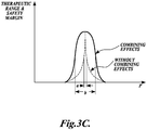
- FIGURE 3C conceptualizes the effect of the applied HIFU power level on the resultant therapeutic range and safety margin of a HIFU treatment regimen.
- range of acoustic power levels where a treatment regimen is both effective and safe can be relatively narrow, as indicated by range "a.” That is, small changes to the HIFU power that result in it falling outside the narrow region "a" make the treatment ineffective or possibly unsafe.
- an elemental treatment volume 80 is shown in top and side views.
- This elemental treatment volume is generally cylindrical with a width W and length L that are both approximately equal to the length of the focal zone of the HIFU transducer.
- the focal zone is moved around the perimeter of the elemental treatment volume with velocity V, the entire cross-section 80a of the elemental treatment volume is treated due to either direct exposure to the HIFU beam or indirect thermal necrosis caused by inward conduction of heat from the treated perimeter.
- FIGURE 3E shows top and side views of a smaller elemental treatment volume 85 having a diameter that is approximately twice the diameter of the focal zone.
- the elemental treatment volume still has well defined boundaries due to the motion of the focal zone around the perimeter of the elemental treatment volume as it is being created.
- the elemental treatment volume has a cross section 85c that is generally uniformly treated all the way through the interior of the volume.
- the disadvantage of this elemental treatment volume 85 is that it is small compared with the elemental treatment volume shown in FIGURE 3D , and therefore more elemental treatment volumes may be required to treat a desired tissue site.
- FIGURE 3F shows top and side views of yet another elemental treatment volume 89 having a diameter that is significantly larger than the diameter of the focal zone of the HIFU transducer.
- cooperative heating of the interior of the elemental treatment volume does not occur and only the perimeter 89c of the elemental treatment volume is ablated.
- the interior may not be treated, as depicted by the open center within the ablated ring.
- the geometry of the elemental treatment volume 89 is not currently preferred for creating the building blocks used to treat a volume of tissue, the geometry may be useful in creating ablated shells around tissue treatment sites as will be discussed in further detail below.
- the building blocks (elemental treatment volumes) may be formed of linear segments created by passing the beam for a number of times along their length.
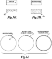
- FIGURES 3G illustrates a scenario in which the entire dose of treatment energy is applied to the tissue in a single pass of the HIFU focal zone along or around the elemental volume, such that the focal zone passes over each particular point only once and never revisits it.
- This type of single-pass focal motion can cause rapid deposition of energy and the production of excess heating, which can result in the formation of large focal or pre-focal bubbles in the tissue that reflect the treatment energy and shield distal regions of the treatment volume. The presence of these bubbles can therefore prevent even ablation at all depths along or around the elemental volume.
- an uneven or "ragged" treatment pattern 91a is created, having different extents of treated tissue at different points on the distal side of the lesion.
- FIGURE 3I illustrates a technique for creating another embodiment of an elemental treatment volume with an arc or segment-type geometry.
- This elemental treatment volume can be used to create rings or other shapes with uniform treatment depths and in one method to form a shell around the desired treatment volume.
- the focal zone of the HIFU transducer is moved back and forth over a portion (e.g., an arc) of the perimeter.
- the back-and-forth motion of the HIFU focus results in tissue ablation at uniform depths because it distributes the acoustic energy over a broader region during the treatment, therefore preventing the formation of large focal or pre-focal bubbles that can reflect energy and result in uneven or "ragged" treatment patterns.
- Multiple treated arcs can therefore be created side by side to complete the treated perimeter of the desired treatment volume.
- the elemental treatment volumes have a height or length that is approximately the same as the length of the focal zone of the HIFU transducer. In some embodiments, the height of an elemental treatment volume may be increased by varying the depth of the focal zone during the application of treatment energy.
- the focal zone 81 of the HIFU beam 83 is steered over the perimeter of the cylindrical elemental treatment volume 80 with a mechanical wobbler at a rate that acts to largely confine the heat within the center 79 of the treatment volume as the elemental treatment volume is being created.
- the focal zone of the HIFU signal is directed around the perimeter of the elemental treatment volume in such a manner that the interior of the treatment volume is ablated by inward thermal conduction, but the energy deposited beyond its exterior boundary remains below the threshold required for inciting thermal or mechanical damage.
- the focal zone 81 of the HIFU beam 83 can be steered around the perimeter of the elemental treatment volume with electronic beam steering which, in one embodiment, may be performed by depositing energy at a set of discrete points around the perimeter rather than via continuous sweeping of the focal zone.
- a substantially non-linear pulsed waveform of HIFU energy such as the waveform 230 shown in FIGURE,8B , is applied to the perimeter of the elemental treatment volume.
- the currently preferred embodiment of this elemental unit volume technique relies on the HIFU treatment waveform being substantially nonlinear in nature, meaning that the originally sinusoidal characteristic of the incident waveform is heavily distorted and no longer sinusoidal in nature by the time it reaches the HIFU focus.
- the presence of nonlinearity in the focal acoustic waveform is indicative of the conversion of energy from the fundamental acoustic frequency into higher harmonics, which in turn are more readily absorbed by the tissue residing in and immediately adjacent to the focal zone.
- the degree of focal waveform nonlinearity favored for this preferred embodiment is that which ensures, at a minimum, the onset of shock in the focal pressure waveform.
- the onset of shock indicates that at some point along the focal waveform, there is a local pressure discontinuity (i.e., the pressure waveform has an infinitely-valued slope).
- the degree of focal nonlinearity useful with this preferred embodiment can also be substantially higher as well, extending beyond the point of initial shock onset to include the formation of a fully-developed shock front within the tissue at the HIFU focus, under some conditions within the tissue volume under treatment.
- a substantial portion of the energy at the fundamental is converted into power at the harmonics of the fundamental frequency of the treatment signals.
- This level of nonlinearity in the focal HIFU waveform typically occurs in conjunction with pressure amplitudes that may result in the formation of bubbles from either acoustic or thermal origins (e.g., inertial cavitation, stable cavitation, or tissue boiling).
- the presence of bubbles in the tissue from any of these sources does not adversely affect the efficacy or safety of the elemental treatment volume technique, as long as the multiple-pass focal scanning approach is used to apply the HIFU energy in a distributed fashion across or along all points on the unit volume's periphery during treatment.
- the presence of such bubbles can be highly advantageous to enable various feedback techniques if desired, due to the fact that bubble scattering cross-sections can be much larger than their geometric size and therefore allow them to serve as easily-detectable indicators of treatment onset and progression.
- the most preferred peak acoustic powers used to attain the desired level of nonlinearity in the HIFU focal zone range from 600-3100 watts, depending upon the depth of the particular elemental tissue volume with respect to the body surface, the design of the HIFU transducer, and its power handling capability.
- These acoustic powers are delivered to the elemental volume in a pulsed fashion, where the most preferred pulses consist of 15-45 cycles at a nominal operating frequency of 1 MHz and are delivered at pulse repetition frequencies (PRFs) of 2-8 kHz. These pulses are then delivered in a series of successive bursts, the total number of which determines the overall treatment time.
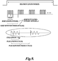
- FIGURE 9 illustrates the acoustic timing structure of a HIFU treatment signal.
- Each treatment signal consists of P bursts of HIFU signals, wherein each burst has N pulses of K cycles at the fundamental frequency (f 0 ) of the HIFU transducer. These bursts of HIFU pulses are then repeated with a burst repetition period of M pulses.
- the following table illustrates the currently preferred ranges for both the acoustic timing and acoustic power parameters to be used in treating tissue with a HIFU transducer with a 125 mm diameter spherical shell and an F-number of 1. It will be appreciated that the parameters listed may be varied with changes in the depth of tissue to be treated and the specifications of the HIFU transducer to be used.
- a cylindrical elemental treatment volume is created by mechanically wobbling the HIFU focus, which is approximately 10 mm. in length and 2 mm. in width in FWHM dimensions in one embodiment, around a trajectory with a most-preferred diameter of 8-12 mm at a rate of nominally 2 Hz.
- the diameter around which the HIFU focus rotates is approximately equal to the HIFU focal zone length and five-fold greater than the HIFU focal zone width.
- the mechanical wobbling and HIFU treatment continue in this fashion for a total treatment duration of 10-50 seconds per elemental volume, in the most-preferred embodiment.
- the treatment duration per unit volume depends on the tissue depth at which the particular elementary volume is created, as well as the overall treatment volume desired. For example, larger overall treatment volumes typically require less treatment time per unit volume, due to the advantages of cooperative heating among many neighboring unit volumes. Similarly, unit volumes created in shallow layers that abut previously-treated deeper layers typically require less time to ablate, owing to modest "pre-heating" of the shallow layers that occurs while the deeper layers are being treated. Arbitrarily large treatment volumes can then be achieved by successive "stacking" of layers composed of some number of these elemental treatment volumes, with a most-preferred axial separation between adjacent layers of 8-12 mm.
- the following table summarizes the preferred ranges of focal motion parameters for use in conjunction with the acoustic waveforms and powers described above.
- Table 3 Preferred Operating Ranges for Selected Focal Motion Parameters Min. Nominal Max. Units Focal wobble diameter Most preferred range 8 10 12 mm Less preferred range 6 10 15 mm Least preferred range 4 10 20 mm Focal wobble revolution rate Most preferred range 1.8 2 2.2 Hz Less preferred range 1 2 4 Hz Least preferred range 0.25 2 8 Hz Axial separation between adjacent layers Most preferred range 8 10 12 mm Less preferred range 6 10 15 mm Least preferred range 4 10 20 mm
- CW continuous-wave
- linear HIFU linear HIFU signal
- the mechanical rotation rate of the HIFU focus about the unit volume diameter is at least 0.25 Hz.
- this rotation rate is at least 1 Hz, while in the most preferred embodiment this rate is nominally 2 Hz. Regardless of the rotation rate used, it is preferable to apply energy over a number of passes (e.g. two or more) around the perimeter using a multiple-pass approach at a rate and power level that allows the entire elemental treatment volume to be ablated in unison, in order to achieve symmetric geometry in the shape of the ablated elemental volume.
- the excess heating produced may cause large focal or pre-focal bubbles to form that can cause shielding and distortion, preventing the production of an evenly ablated tissue site, as illustrated in FIGURE 3G-3H and described previously.
- large focal or pre-focal bubbles can detract from the uniformity of treatment when a single-pass approach is used, the presence of bubbles in the tissue from either acoustic or thermal origins does not adversely affect treatment efficacy as long as the HIFU focus is scanned along or around the unit volume using multiple passes to temporally distribute the treatment energy directed at any one point in the volume.
- the size of the elemental treatment volume is preferably selected so that a center region 79 can be indirectly treated while not unduly increasing the treatment time required to treat a desired volume of tissue. If the size of the elemental treatment volume is too large, the center region 79 will not be ablated by effective conduction of heat into the interior of the volume. Conversely, if the size of the elemental treatment volume is too small, then the time required to treat the desired treatment volume must be adjusted to avoid over-dosing the elemental volume and potentially causing damage to collateral tissues. In addition, the time to create each elemental treatment volume may decrease as the focal zone is moved proximally toward the surface of the body, due to the residual heat persisting in the treatment volume from ablation of the more distal elemental volumes.
- the method of creating the elemental treatment volumes takes advantage of several features of HIFU therapy resulting from the synergistic effects of highly-nonlinear acoustic waveforms and the mechanical or electronic motion of the HIFU focus about the perimeter of the unit volume.
- These combined effects comprise a set of operating points that result in the enhanced safety and efficacy observed when using this treatment method.
- This set of operating points includes a combination of the following: (1) The elemental treatment volume is ablated in such a way that the interior region is primarily destroyed through inward conduction of heat, not direct ablation by HIFU. This feature enlarges the size of the elemental volume without increasing the HIFU dose that has to be delivered to the tissue to do so.
- the motion of the HIFU focal zone about the elemental treatment volume perimeter is accomplished by making multiple passes around the perimeter using a specified rotation rate, as opposed to making one a single pass around the circumference of the unit volume to achieve ablation. This feature allows the tissue within the elemental treatment volume to be ablated with uniform, smooth boundaries and equal length at substantially all points around the perimeter.
- the elemental treatment volume is subjected to highly concentrated acoustic energy only in the focal region of the HIFU beam by virtue of the use of a highly nonlinear acoustic waveform that dramatically enhances the heating rate in the focal zone.
- the fundamental acoustic frequency of the HIFU applicator is kept low enough to ensure safe propagation through untargeted collateral tissues.
- the treatment system can operate without reliance on temperature feedback monitoring, thereby resulting in faster treatment and reduced system complexity and cost.
- the combination of all these attendant benefits ensures adequate efficacy of the treatment, obviating the need for thermometric techniques to determine the temperature within the treatment volume to verify that temperature levels required for thermal necrosis are being achieved.
- the combination of the feature set described above takes advantage of synergistic effects that allow each unit volume to be ablated with precise boundaries and minimal thermal invasiveness to collateral tissues outside the treatment volume.
- FIGURES 3J and 3K illustrate one technique for using the elemental treatment volumes 80 to treat a desired volume of tissue.
- a three dimensional pattern of adjacent elemental treatment volumes are created such that together they form an ablated shell that surrounds all or a portion of a desired tissue treatment volume.
- an ablated shell 87 is formed from a number of smaller ablated elemental treatment volumes 80, 82, 84, 86, 88, etc.
- Each of the elemental treatment volumes is created sufficiently close together to form a necrosed shell or barrier of ablated tissue between the encapsulated tissue and its blood supply.
- the elemental treatment volumes 80, 82, 84, 86, 88, etc. are created adjacent to each other in annular patterns of increasing internal diameter that extend from the distal end of the desired tissue treatment volume to approximately midway in the tissue volume, where the diameter of the treatment volume is the largest. The diameter of the annular patterns then progressively decreases towards the proximal end of the tissue volume to be treated. Together the annular patterns create a shell with a "hollow" interior space 90 that encapsulates a portion of the desired tissue volume to be treated.
- each elemental treatment volume in an in vivo porcine thigh was treated by forming a shell of 20 elemental treatment volumes around the surface of the ball in approximately 320 seconds, where each elemental treatment volume has a volume of approximately 1 cubic cm.
- the individual elemental treatment volumes in each layer of the shell are created in a pattern such that adjacent elemental treatment volumes are not created sequentially.
- the pattern of elemental treatment volumes in each layer of the shell is created in a manner that maximizes the distance between two sequentially created elemental treatment volumes.
- the shell 87 illustrated in FIGURES 3J and 3K is shown as being hollow, it will be appreciated that it in some circumstances it may be desirable to create one or more elemental treatment volumes within the interior of the shell to actively necrose some or all of the tissue inside the shell 87.
- the number and spacing of the elemental treatment volumes can be decided by the physician based on experience, the time available for treatment, the type of tissue being treated or other factors.
- a processor can be programmed to determine if the interior of the shell should be empty or filled with one or more elemental treatment volumes.
- the shell 87 is shown in FIGURE 3J as being substantially sealed about its outer surface. However, it will be appreciated that a shell 87 can still be created even if there are gaps between the individual elemental treatment volumes. How close the elemental treatment volumes are placed in order to create the shell may be based on the type of tissue being treated, the thermal conductivity of the tissue, its absorption characteristics, or other factors.
- shells of elemental treatment volumes can be used to treat the desired tissue volume.
- layers of horizontally spaced adjacent elemental treatment volumes can be created in the desired tissue volume.
- the distance between elemental treatment volumes in a layer can be closely spaced or more spread apart.
- FIGURES 4A-4B show an alternative technique for creating an ablated shell 92 around a tissue volume in accordance with the disclosed technology.
- an ablated shell comprises a stacked series of toroids, each having a varying internal diameter.
- a toroid 94 of minimum internal diameter (or a solid disk) is placed at the distal end of the tissue to be treated with respect to the HIFU transducer. Additional toroids are created proximally to the distal toroid 94, including toroids 95, 96, 98 of increasing diameter up to a toroid 100 where the toroid has a maximum internal diameter.
- each of the toroids 94-108 when stacked, define a shell with a "hollow" (i.e., un-ablated) region 110 that encapsulates a volume of the tissue to be treated and isolates it from its blood supply.
- the outer diameter of the toroids 94-108 is selected to correspond to the outer dimension of the fibroid in order to minimize the volume of tissue that is directly ablated with HIFU.
- the outer diameters of the toroids 92-106 are selected to be within a set distance internal to the fibroid's outer boundary in order to allow the fibroid tissue external to the ablated shell 92 to be partially or completely destroyed via thermal necrosis (due to heat conducted from the ablated shell 92) and/or secondary injury pathway mechanisms (ischemia, inflammation, apoptosis, et al.).
- the inner diameters of the toroids 94-108 correspond to the outer diameter of the tissue volume such that the interior 110 of the ablated shell 92 created is slightly larger than the tissue volume, perhaps allowing a more complete kill of tumor tissue at the expense of killing a small amount of surrounding healthy myometrium.
- Another advantage of such an embodiment is the ability to create the ablated shell 92 such that it overlaps the endometrial lining, thus necrosing at least some of the nearby endometrium which may reduce menorrhagia symptoms.
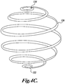
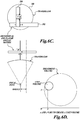
- FIGURE 4C shows yet another embodiment of an ablation pattern that creates an ablated shell to encapsulate a tissue volume and isolate it from an external blood supply.
- an ablated shell is created from a spiral pattern 120.
- the spiral has a minimum diameter at a distal end 122 of the tissue volume to be treated, expands to a maximum diameter at approximately the mid point of the tissue volume, and then progressively decreases in diameter towards the proximal end 124 of the tissue volume.
- Each loop of the spiral pattern 120 is sufficiently close to an adjacent loop that the tissue is actively necrosed in order to create an ablated shell around a tissue volume that cuts off the tissue in the shell from its blood supply.
- the spiral pattern 120 could also be used to create the smaller elemental treatment volumes described above and shown in FIGURES 3A and 3B depending on the size of the focal zone of the HIFU transducer and the desired size of the elemental treatment volumes.
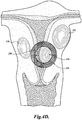
- FIGURE 4D illustrates a uterus having three different types of fibroids including an intramural fibroid 130, a subserosal fibroid 132, and a submucosal fibroid 134.
- an ablated shell 135 is created to encapsulate the entire submucosal fibroid 134 on one side of the uterine wall as well as a portion of the nearby endometrium tissue 136 on the opposite uterine wall.
- the shape of the ablated shells is shown as being generally spherical in FIGURES 3J-3K , 4A-4B and 4C , it will be appreciated that other shapes, such as conical or double conical, ovoid (e.g., egg shaped), or rectangular could be used.
- the particular shape of the shell created may depend on the shape of the tissue volume to be treated and the ability of the equipment used to steer the focal zone of the HIFU transducer in a desired pattern. Any shell shape of ablated tissue that forms a barrier between tissue internal to the shell and its external blood supply will function to allow the encapsulated tissue to ischemically necrose when left in the body.
- ablating an excessively large or irregularly shaped shell one could ablate two or more regularly-shaped shells adjacent to each other to treat most or all of the desired volume (e.g., 2 spherical shells could be ablated side-by-side inside an oblong tumor, rather than ablating one oblong shell).
- a matrix or "honeycomb" of ablated elemental tissue volumes with interspersed regions of non-ablated tissue which subsequently ischemically necrose in situ.
- Such a matrix could involve regular or random spacing of ablated elemental treatment volumes to accomplish the same effect, and the matrix could consist of numerous closed shells (e.g., spherical shells) or layers of stacked / overlapping elemental treatment volumes.
- the user need only manipulate the HIFU system so as to center an overlay of the projected shell within the image of the target tissue, expand the diameter of the shell to desired dimensions (e.g., just inside periphery of the tumor), and then hold the system stationary relative to the target tissue while the system automatically ablates the specified shell pattern.
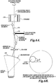
- FIGURE 5 shows one embodiment of a HIFU treatment device that can be used to treat tissue in the manner described above.
- the HIFU treatment device 150 is a hand held or hand guided applicator device that includes an imaging transducer 152 and a HIFU transducer 154.
- the imaging transducer 152 is fixed in position to capture images of tissue within a body that includes the focal zone of the HIFU transducer 154.
- the focal zone of the HIFU transducer 154 can be mechanically and/or electrically steered to ablate a number of elemental treatment volumes that are adjacently positioned to create a shell that surrounds or encapsulates a desired tissue volume or to create another pattern.
- the focal zone of the HIFU transducer 154 is moved in such a way as to ablate a pattern of elemental treatment volumes in order to create a shell around the treatment volume or to create another pattern of elemental treatment volumes.
- the treatment device 150 is coupleable to other components of the treatment system including an image processor and display required to operate the imaging transducer 152 and produce images of the tissue volume.
- a signal source required to drive the HIFU transducer and a computer to orient the focal zone of the HIFU transducer in a pattern to create the elemental treatment volumes in a desired pattern such as a shell around the tissue volume are also included.
- FIGURE 6 illustrates one embodiment of a more detailed mechanism for treating the internal body tissues with HIFU signals to create a series of elemental treatment volumes in a shell or other pattern.
- the treatment device 150 includes a HIFU transducer 154.
- the HIFU transducer 154 has a fixed focal zone, as defined by the curvature of the piezoelectric elements that comprise the transducer head.
- a flexible membrane that does not significantly reflect HIFU signals is positioned in front of the HIFU transducer to form a chamber in which liquid can be introduced, stored, and/or circulated.
- a liquid such as water or de-gassed water then fills the liquid chamber and surrounds the transducer 154 to serve as an acoustic couplant to the tissue.
- a port 156 connects the treatment device to a pump to allow the liquid of a constant volume to flow around the HIFU transducer.
- a linear actuator 160 or motor raises or lowers the HIFU transducer 154 within a housing of the treatment device 150 via a threaded rod or other mechanism. By adjusting the height of the transducer 154 within the housing, the depth where the HIFU signals are delivered within the body can be controlled.
- the treatment device 150 includes an offset bearing 170 that, when rotated by a motor 168, wobbles an end of a shaft 172 around the center of the offset bearing 170.
- the HIFU transducer 154 is coupled to the other end of the shaft 172 through a slidable bearing.
- a linear actuator 164 or motor positions a spherical bearing 174 that surrounds the shaft 172 towards or away from the offset bearing 170. The position of the spherical bearing 174 on the shaft 172 controls the angular orientation of the focal zone of the HIFU transducer 154.
- toroidal rings of ablated tissue or annular patterns composed of ablated cylinders/spheres can be created in the body at various depths.
- the focal zone of the HIFU transducer will trace out a substantially circular pattern off a central axis of the treatment device 150, thereby allowing the creation of an elemental treatment volume at a desired location in the body as shown in FIGURE 6B .
- the elemental treatment volume can be created at the top and bottom of the shell depending on the depth of the focal zone.
- a physician obtains an image of the tissue volume with the imaging transducer 152 and adjusts the radius of a marker ring on the image or interacts with some other graphical user interface or keyboard to define the boundaries of the desired shell. Based on the radius of the marker ring, a computer calculates the volume or shape of the ablated shell to be created in the body. The HIFU transducer and motors within the treatment device 150 are then activated such that a pattern of elemental treatment volumes is ablated to form the shell that surrounds or encapsulates the tissue volume or some other desired pattern of elemental treatment volumes.
- the focal zone of the HIFU transducer may be continually moved until a treatment volume is ablated or the focal zone may be moved to discrete positions around the perimeter of the elemental treatment volumes and a HIFU signal applied to create the elemental treatment volumes.
- the linear actuator 160 that adjusts the focal zone depth, the linear actuator 164 that adjusts the angle of the HIFU transducer, and the motor 168 that rotates the shaft 172 are simultaneously operated to create a spiral shell ablation pattern of the type shown in FIGURE 4C .
- the patient may be injected with a contrast agent to allow the physician to confirm that blood perfusion has been appropriately reduced or eliminated within the targeted tissue volume.
- a contrast agent to allow the physician to confirm that blood perfusion has been appropriately reduced or eliminated within the targeted tissue volume.
- Non-perfusion would provide a strong indication that the treated tissue volume will undergo (or has undergone) ischemic necrosis.
- contrast agents are well known in the art for use with various different imaging modalities including ultrasound, MRI, x-ray, CT, etc.
- FIGURES 6C AND 6D illustrate another alternative embodiment where a transducer 180 is moved in two orthogonal directions (x,y) by a pair of linear actuators 182, 184.
- the linear actuators which could be motors that drive a worm gear or other mechanisms, are computer controlled so that the position of the focal zone of the HIFU transducer 180 is moved as desired.
- a third motor or actuator (not shown) can be computer controlled to vary the height of the transducer 180 to change the depth of the focal zone.
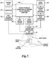
- FIGURE 7 illustrates a basic block diagram of a HIFU ultrasound treatment system in accordance with one embodiment of the disclosed technology.
- a patient treatment device includes both a HIFU transducer 154 and an ultrasound imaging transducer 152.
- the transducers may be separate devices as shown in FIGURE 6 or may be an integrated device with HIFU and imaging ultrasound elements located on the same transducer head.
- Controlling the operation of the imaging and HIFU transducers is a system controller 200 that may include one or more general purpose or special purpose programmed processors that are programmed to perform the functions described herein.
- the system controller 200 supplies control signals to a HIFU control unit 202 that selects the power of the HIFU signals to be provided by the HIFU transducer 154.
- the operating power level is selected by transmitting a number of test signals at different power levels and analyzing the echo signals created in response to the transmitted test signals.
- the operating power level for HIFU treatment is selected when a desired characteristic of an echo signal is observed, such as when a certain distribution of power at different fundamental and harmonic frequency components is detected within the echo signal.
- This particular embodiment for selecting the operating power level based on a pre-treatment acoustic assessment the spectral power distribution will be described in more detail subsequently. Further detail of possible methods of selecting and controlling the HIFU power can be found in U.S. Patent Application No. 12/537,217 filed August 6th, 2009 ( U.S. Patent Publication No. 2010/0036292 ).
- the imaging transducer 152 is controlled by an imaging ultrasound controller 204 that includes conventional ultrasound components such as a transmit/receive switch, beam former, RF amplifiers and signal processors.
- the output of the ultrasound controller 204 is fed to an ultrasound signal processor 210 that operates to produce ultrasound imaging signals for display on a video monitor 212 or other display.
- the image signals can also be stored on a computer readable media (DVD, video tape, etc.), printed by a printer or otherwise stored for later diagnosis or analysis.
- a computer controlled steerer 205 (or position control) is controlled by the system controller 200 to create a number of elemental treatment volumes to treat a desired volume of tissue.
- the computer controlled steerer 205 mechanically adjusts the angular orientation or x,y position of the HIFU transducer 154 and the depth of the focal zone to direct the HIFU energy at a desired location.
- the computer controlled steerer 205 electronically adjusts the angular orientation or x,y position of the focal zone of the HIFU transducer 154 and the depth of the focal zone of the HIFU transducer 154 to create the elemental treatment volumes.
- a footswitch 214 allows a physician or their assistant to selectively deliver HIFU energy to the patient in order to treat a tissue site.
- the physician can manually change the size and shape of the treatment volume and other functions of the system using one or more controls on a control panel 216.
- the system may include an image position control 220 that changes the orientation of the imaging transducer 152 so that the physician can view the desired target tissue volume to be treated at different angles or in different planes.
- the image position control be either mechanical or electronic and is controlled by the system controller 200.
- the system shown in FIGURE 7 does not require the use of temperature data or other feedback control to treat tissue. Because the temperature data or feedback control is not required, systems for detecting the data, such as an MRI machine are not required. This allows the system disclosed herein to be made small enough such that it can be used in a physician's office.
- a power level used to treat the tissue is selected based on the detected energy in one or more harmonics of the fundamental frequency. Another way of detecting the same effect is to measure the conversion of energy from the fundamental frequency of the treatment signal to the harmonics of the fundamental with changes in applied power and to use the measured conversion as a way to select a power level for the treatment signals.
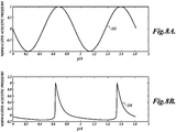
- FIGURE 10 shows a curve 300 that plots the amount of energy backscattered from the focal zone that is retained at the fundamental frequency of a HIFU treatment signal versus changes in electrical power delivered to the HIFU transducer.
- the curve reaches a normalized maximum of 1.0 at approximately 200 watts where substantially all the energy (100%) in a backscatter signal detected is contained at the fundamental frequency.
- the electrical power delivered is increased, energy is converted from the fundamental frequency to harmonics of the fundamental frequency and the fundamental energy retained (FER) decreases.
- the FER curve 300 can be used to select the transmit power of the HIFU signals that will be used to treat the patient. It is possible, depending on tissue variance levels, that the FER curve is the only information needed to determine successful treatment.
- the FER curve 300 is computed by applying a number of test signals at different power levels to the treatment site, detecting received backscatter signals and determining how the frequency distribution of the energy in the backscatter signals differs from what the distribution would look like if the tissue were operating like a linear system. For example, for the linear system model, if a test signal of 500 watts of electrical power produces X energy at the fundamental frequency in the received backscatter signal, then 1000 watts of applied electrical power should produce 2X of energy at the fundamental frequency. Any variation from 2X deviates from a linear system and is therefore related to how much energy is being converted into energy at the harmonic frequencies.
- those points on the curve in a region 302 are associated with a signal to noise (S/N) ratio that may make their data unreliable.
- those points on the curve in a region 306 are produced at power levels where cavitation is likely in the tissue. Because the tissue is changing state with cavitation, the backscatter signals received at this power level may also not be reliable to determine how much power is being converted to harmonics of the fundamental of the treatment signals.
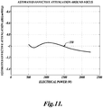
- FIGURE 11 shows a curve 350 that plots the estimated attenuation between the HIFU transducer and the focal zone of the HIFU transducer versus changes in applied transmit power.
- the FER curve 300 shown in FIGURE 10 and the attenuation curve 350 shown in FIGURE 11 are used to select a treatment power level.
- FIGURE 12 shows a curve 360 that plots the energy contained at the fundamental frequency around the focal zone versus changes in applied electrical power.
- a curve 370 plots changes in the energy contained in the harmonics of the fundamental frequency with changes in applied electrical power around the focal zone and a curve 380 plots the total power applied to the tissue around the focal zone (i.e., power at the fundamental and at the harmonics) versus changes in applied power.
- the curve 370 is used to select the treatment power of the HIFU signals. For example, empirically determined data obtained from animal trials or from other sources, may be used to select a desired power that should be delivered to the tissue at harmonics of the fundamental frequency. In trials on in vivo porcine thighs, a level of 100-200 watts of harmonic power at the focal zone has been found to produce uniformly necrosed elemental treatment volumes with little collateral tissue damage, when used in conjunction with the acoustic waveform timing and motion profile parameters described herein. The curve 370 is used to determine what the input electrical power of the treatment signals should be in order to produce 100-200 watts of harmonic power.
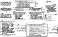
- FIGURE 13 is a signal processing flow diagram showing the steps used to compute a FER curve in accordance with one embodiment of the disclosed technology.
- the metric by which the HIFU output is measured (typically the transmit power level) is determined.
- the transmit power level can be calculated from the current and voltage waveforms of the digitized transmit signals, or from either the current or voltage waveform of the transmit signals in conjunction with the impedance of the HIFU transducer. If the system state is known and stable, then the initial state can be reused when calculating an FER curve.
- the RF backscatter signals from a number of test signals transmitted at different power levels are detected, digitized and stored in a memory or other computer readable media.
- a depth range to interrogate is selected that includes an area around the focal zone of the HIFU transducer.
- the RF backscatter signals are filtered to determine the energy at the fundamental frequency of the transmit signals.
- the minimum transmit power needed to obtain backscatter signals with a good signal-to-noise (S/N) ratio at the fundamental frequency is determined. Such determination may be made by nearest neighbor correlation or by determining where the power detected in the window appears to be linear with changes in excitation power.
- a calculation is made at 418 to determine a transmit power level where cavitation in the tissue begins. Such a power level can be determined using, for example, a template method, nearest neighbor correlation or a noise floor calculation. Each of these techniques is considered known to those of ordinary skill in the art of ultrasound signal processing.
- the energy at the fundamental frequency in a sliding window is determined for various transmit powers.
- the window size which is typically determined by transmit pulse attributes, may be selected in response to user input, recalled from memory, or dynamically calculated.
- the energy in the window at the fundamental frequency is determined and the window is then moved to the next set of data points.
- the result is a surface plot 424 of the energy at the fundamental frequency at various depths in the tissue versus changes in transmit power.
- the amount of fundamental energy retained (FER) in the backscatter signal for each depth in the depth range is determined.
- the energy at the fundamental contained in the backscatter signal for a particular depth is compared with the energy that would be expected if the tissue were operating as a linear system.
- the expected energy E exp may be determined by multiplying the energy E 0 at the fundamental detected at a lower power P L that is sufficient to produce signals with a good signal to noise ratio by the quotient of the transmit power in question P H divided by P L .
- the differences between the energy actually detected at the fundamental and the expected energy E exp is used to produce a surface plot 428 of the local FER values versus depth and applied power.
- the process described above may be repeated for different interrogation angles or positions around the focal zone at 430.
- the results obtained for the local FER values are compounded (such as by averaging the value) for each angle interrogated (if any).
- the compounded results are fit to a polynomial (which may be first order such as a line) or other mathematically defined function.
- the FER curve is normalized to one, such that all values in the FER curve are less than one for depths and power levels where energy is being converted from the fundamental to the harmonics of the fundamental.
- the filtering at 414 can be done with a digital FIR (finite impulse response) filter and an FFT (fast Fourier transform) can be performed at 420 to determine the amount of energy in the received backscatter signals at the fundamental frequency.
- the signal processing can be performed at baseband by multiplying the backscatter signal by the carrier signal and applying a low pass filter such that the amplitude of the remaining signal is indicative of the energy contained at the fundamental.
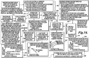
- a computer such as the system controller 200, is programmed to make an estimation of what the attenuation is in the tissue path from the transducer to the tissue site to be treated. Attenuation values can be recalled from a memory that stores values based on prior experiments or from literature studies for well known tissue types. However because each patient's physiology is different, the attenuation can also be estimated based on the response of the tissue to one or more test signals.
- the attenuation of the HIFU signal between the HIFU transducer and the target treatment site is determined by applying a number of test signals at different power levels.
- the actual power of the signals applied by the HIFU transducer is determined either from previously determined measurements or from the digitized current and voltage waveforms applied to the transducer. Alternatively, if the impedance of the transducer is known, the current or voltage waveforms can be used to calculate the power.
- a number of RF backscatter signals are detected at 504.
- signals are detected with a wide bandwidth receiver (e.g. the imaging transducer 152) that can detect signals at for example, the 2 nd -4 th harmonics of the transmit signal (other harmonics may be used if available).
- a depth range is selected for which the attenuation is to be measured.
- the depth range will typically include the focal zone of the transducer.
- a window of data in each of the backscatter signals is selected that includes the selected depth range.
- the system controller 200 or other computer performs an FFT or some other frequency analysis to determine how much energy is present in each of the 2 nd -4 th or higher harmonics in the backscatter signals. The energy in the harmonics is then corrected for the response of the detection system due to, for example, roll-off in the pre-amplifiers or the frequency response of the detecting transducer.
- the delivered power for which the RF backscatter signals have a good signal-to-noise (S/N) ratio at the harmonics is determined. This power will likely be greater than that required to produce signals with a good S/N ratio at the fundamental frequency.
- the power level at which cavitation begins is also determined in the manner described above.
- a surface plot of the energy at different frequencies versus changes in applied electrical power is calculated at 524.
- the energy at each harmonic versus applied electrical power is calculated at 526.
- the steps 510-526 can be repeated for different interrogation points at 528. In one embodiment, measurements are made at 10 points surrounding the desired treatment site.
- the results are compounded such as by averaging at 530.
- an assumption is made that harmonics are emanating from the vicinity of the focal zone of the HIFU transducer and are created predominantly as result of the nonlinear propagation of the applied HIFU signal. Therefore it is also assumed that signals at the harmonic frequencies are only attenuated on a one-way path from the focal zone back to the detection transducer.
- signal amplitudes for harmonics generated in tissue should experience a roll-off. For example, if the amount of harmonics has saturated, the roll-off follows a 1/n behavior (where n indicates the n th harmonic). This roll-off should be corrected for and can be determined by the FER value.
- any difference in amplitude between the harmonic peaks may be attributed to attenuation.
- the energy level of each harmonic at a particular input power level is determined and fitted with a polynomial (or a line).
- the slope of the polynomial divided by the total length of the tissue path at the point where the signal is measured gives the attenuation of the HIFU signals in units of dB/MHz-cm. This calculation is performed for other applied input powers between the minimum required for good signal-to-noise ratio and the power level at which cavitation begins. The result is an attenuation curve that plots attenuation versus applied input power.
- a local attenuation value such as in a fibroid itself.
- the HIFU transducer may be moved with respect to the tissue or its focal zone changed and the new attenuation curve determined in the manner described above.
- the local attenuation at any given input power is therefore equal to the difference of the attenuation values at each depth, multiplied by their respective depths, divided by the difference in depths.
- an appropriate input power for treatment is determined by multiplying the input power by the attenuation curve 350 at a number of power levels between the minimum needed for a good S/N ratio and the power level where cavitation begins.
- scaling the input power by the attenuation curve 350 results in the curve 380 shown in FIGURE 12 .
- the curve 360 is calculated by scaling the curve 380 by the FER curve 300.
- the power in the harmonics curve 370 can be calculated by subtracting the curve 360 from the curve 380. From the curve 370 the appropriate input power necessary to achieve the desired harmonic power in the tissue can be determined as indicated above.
- the power of the treatment signals used to treat the tissue can also be predetermined and recalled from stored memory based on a measured characteristic of the tissue in question. If the local attenuation of the tissue is known, a FER curve based on previously performed studies can be used to predict how much energy should be applied to achieve a desired harmonic power at the treatment site. Alternatively, if the FER curve is determined for the tissue in question, a treatment power can be selected based on previously performed studies.
- tissue path that is effectively non-attenuative (e.g., urine contained within the bladder) and reduce the empirically-determined power value known for that tissue depth by the appropriate amount to account for the non-attenuative portion. For example, if the tissue path for a 10 cm treatment depth contains a 2-cm segment composed of urine in the bladder, then the empirically-determined power value for a 8-cm treatment depth can be applied instead as a first-order approximation of the appropriate HIFU output level.
- tissue path for a 10 cm treatment depth contains a 2-cm segment composed of urine in the bladder
- the energy source used to create the ablated shell is HIFU in the disclosed embodiments, not according to the invention other energy sources could be used such as radiation, lasers, RF, microwaves, cryoablation, etc. Some of these energy sources are minimally invasive such that they must be delivered to the tissue volume with a catheter, endoscope, or the like. Applying energy from these energy sources ablates the perimeter of the tissue volume to create an ablated shell.
- the HIFU transducer may be insertable in to the body such as transvaginally or rectally.
- the tissue volumes to be treated can be seen from the location of the HIFU transducer, then images of the tissue can be obtained with image sensors other than ultrasound image sensors.
- the imaging of the desired treatment volume may be done with another type of imaging modality such as MRI, x-ray, infrared, or the like in a manner that allows a physician to confirm that the HIFU is being delivered to the area of desired target tissue volume. Therefore, the scope of the invention is to be determined from the following claims and equivalents thereof.
Applications Claiming Priority (2)
| Application Number | Priority Date | Filing Date | Title |
|---|---|---|---|
| US12/753,813 US9050449B2 (en) | 2008-10-03 | 2010-04-02 | System for treating a volume of tissue with high intensity focused ultrasound |
| PCT/US2011/031129 WO2011123862A2 (en) | 2010-04-02 | 2011-04-04 | Office-based system for treating uterine fibroids or other tissues with hifu |
Publications (3)
| Publication Number | Publication Date |
|---|---|
| EP2552546A2 EP2552546A2 (en) | 2013-02-06 |
| EP2552546A4 EP2552546A4 (en) | 2014-12-31 |
| EP2552546B1 true EP2552546B1 (en) | 2017-10-18 |
Family
ID=44712872
Family Applications (1)
| Application Number | Title | Priority Date | Filing Date |
|---|---|---|---|
| EP11763567.2A Not-in-force EP2552546B1 (en) | 2010-04-02 | 2011-04-04 | Office-based system for treating uterine fibroids or other tissues with hifu |
Country Status (7)
| Country | Link |
|---|---|
| US (3) | US9050449B2 (zh) |
| EP (1) | EP2552546B1 (zh) |
| JP (1) | JP5805176B2 (zh) |
| KR (1) | KR101903539B1 (zh) |
| CN (2) | CN107050674B (zh) |
| CA (1) | CA2795166A1 (zh) |
| WO (1) | WO2011123862A2 (zh) |
Families Citing this family (34)
| Publication number | Priority date | Publication date | Assignee | Title |
|---|---|---|---|---|
| US10219815B2 (en) | 2005-09-22 | 2019-03-05 | The Regents Of The University Of Michigan | Histotripsy for thrombolysis |
| US20090240146A1 (en) * | 2007-10-26 | 2009-09-24 | Liposonix, Inc. | Mechanical arm |
| EP2331207B1 (en) | 2008-10-03 | 2013-12-11 | Mirabilis Medica Inc. | Apparatus for treating tissues with hifu |
| US9050449B2 (en) | 2008-10-03 | 2015-06-09 | Mirabilis Medica, Inc. | System for treating a volume of tissue with high intensity focused ultrasound |
| US8903488B2 (en) | 2009-05-28 | 2014-12-02 | Angiodynamics, Inc. | System and method for synchronizing energy delivery to the cardiac rhythm |
| US9895189B2 (en) | 2009-06-19 | 2018-02-20 | Angiodynamics, Inc. | Methods of sterilization and treating infection using irreversible electroporation |
| WO2012006053A1 (en) * | 2010-06-29 | 2012-01-12 | Kullervo Henrik Hynynen | Thermal therapy apparatus and method using focused ultrasonic sound fields |
| US9573000B2 (en) | 2010-08-18 | 2017-02-21 | Mirabilis Medica Inc. | HIFU applicator |
| WO2012051433A2 (en) | 2010-10-13 | 2012-04-19 | Angiodynamics, Inc. | System and method for electrically ablating tissue of a patient |
| US9078665B2 (en) | 2011-09-28 | 2015-07-14 | Angiodynamics, Inc. | Multiple treatment zone ablation probe |
| EP2768396A2 (en) | 2011-10-17 | 2014-08-27 | Butterfly Network Inc. | Transmissive imaging and related apparatus and methods |
| CN104619263B (zh) * | 2012-07-16 | 2018-07-17 | 米瑞碧利斯医疗公司 | 超声引导治疗的人机接口和设备 |
| WO2014055708A1 (en) * | 2012-10-02 | 2014-04-10 | Ardent Sound, Inc. | Motion mechanisms for ultrasound transducer modules |
| EP2934333B1 (en) * | 2012-12-21 | 2019-05-15 | Volcano Corporation | Method for multi-frequency imaging using high-bandwidth transducer outputs |
| US20140277035A1 (en) * | 2013-03-14 | 2014-09-18 | SonaCare Medical, LLC | System and method for r-mode imaging and treatment planning |
| US9667889B2 (en) | 2013-04-03 | 2017-05-30 | Butterfly Network, Inc. | Portable electronic devices with integrated imaging capabilities |
| WO2015027164A1 (en) | 2013-08-22 | 2015-02-26 | The Regents Of The University Of Michigan | Histotripsy using very short ultrasound pulses |
| US20170072228A1 (en) * | 2014-03-31 | 2017-03-16 | University Of Washington | Methods and systems for selectively disrupting tissue with high intensity focused ultrasound |
| ES2948135T3 (es) | 2015-06-24 | 2023-08-31 | Univ Michigan Regents | Sistemas de terapia de histotripsia para el tratamiento del tejido cerebral |
| US10660691B2 (en) | 2015-10-07 | 2020-05-26 | Angiodynamics, Inc. | Multiple use subassembly with integrated fluid delivery system for use with single or dual-lumen peristaltic tubing |
| ES2952835T3 (es) * | 2015-12-01 | 2023-11-06 | Classys Inc | Dispositivo generador de ondas ultrasónicas terapéuticas |
| CN107921281B (zh) * | 2016-05-19 | 2020-07-21 | 山下洋八 | 超声波照射装置以及超声波照射系统 |
| CN106175836B (zh) * | 2016-07-29 | 2020-11-03 | 上海爱申科技发展股份有限公司 | 超声病灶定位方法 |
| US10300308B2 (en) | 2016-09-23 | 2019-05-28 | SonaCare Medical, LLC | System, apparatus and method for high-intensity focused ultrasound (HIFU) and/or ultrasound delivery while protecting critical structures |
| US10905492B2 (en) | 2016-11-17 | 2021-02-02 | Angiodynamics, Inc. | Techniques for irreversible electroporation using a single-pole tine-style internal device communicating with an external surface electrode |
| TWI659208B (zh) * | 2016-11-22 | 2019-05-11 | 財團法人工業技術研究院 | 可調整聚焦深度之高能超音波探頭及其調整方法 |
| US11260249B2 (en) * | 2018-07-19 | 2022-03-01 | Sonablate Corp. | System, apparatus and method for high intensity focused ultrasound and tissue healing activation |
| US11813484B2 (en) | 2018-11-28 | 2023-11-14 | Histosonics, Inc. | Histotripsy systems and methods |
| US20220304656A1 (en) * | 2019-06-19 | 2022-09-29 | Theraclion Sa | Device for and method for preparing of a treatment of a patient with high-intensity focused ultrasound |
| US11944847B2 (en) * | 2019-08-05 | 2024-04-02 | Profound Medical Inc. | System and method for open-loop ultrasound therapy to the prostate including restricting the therapy delivered to a predetermined angular range |
| US11813485B2 (en) | 2020-01-28 | 2023-11-14 | The Regents Of The University Of Michigan | Systems and methods for histotripsy immunosensitization |
| CN113893468B (zh) * | 2020-06-22 | 2023-03-21 | 飞依诺科技(苏州)有限公司 | 治疗用超声波的调整方法、装置、计算机设备和存储介质 |
| DE102021205077B4 (de) * | 2021-05-19 | 2023-02-16 | Siemens Healthcare Gmbh | Druckkontrollsystem zum Bereitstellen eines auf einen Patienten während einer prä-interventionellen Bildgebung mit einem Bildgebungssystem auszuübenden Drucks |
| US11524183B1 (en) | 2022-03-11 | 2022-12-13 | Sonablate Corp. | System, apparatus, and method for delivering ultrasound |
Family Cites Families (146)
| Publication number | Priority date | Publication date | Assignee | Title |
|---|---|---|---|---|
| DE1289617B (de) * | 1964-06-06 | 1969-02-20 | Siemens Ag | Ultraschall-Diagnostikgeraet |
| US3480002A (en) * | 1967-01-24 | 1969-11-25 | Magnaflux Corp | Medical ultrasonic scanning system |
| US3676584A (en) * | 1970-07-13 | 1972-07-11 | Chris J Plakas | Echo coincidence ultrasonic scanning |
| FR2234797A5 (zh) * | 1973-06-22 | 1975-01-17 | Ducellier & Cie | |
| US4059098A (en) * | 1975-07-21 | 1977-11-22 | Stanford Research Institute | Flexible ultrasound coupling system |
| US4097835A (en) * | 1976-09-20 | 1978-06-27 | Sri International | Dual transducer arrangement for ultrasonic imaging system |
| US4185502A (en) * | 1977-10-11 | 1980-01-29 | Ralph Frank | Transducer coupling apparatus |
| US4282755A (en) * | 1979-12-05 | 1981-08-11 | Technicare Corporation | Transducer drive and control |
| US4347850A (en) * | 1980-03-19 | 1982-09-07 | Indianapolis Center For Advanced Research, Inc. | Direct water coupling device for ultrasound breast scanning in a supine position |
| US4484569A (en) * | 1981-03-13 | 1984-11-27 | Riverside Research Institute | Ultrasonic diagnostic and therapeutic transducer assembly and method for using |
| US4665913A (en) * | 1983-11-17 | 1987-05-19 | Lri L.P. | Method for ophthalmological surgery |
| US5143073A (en) * | 1983-12-14 | 1992-09-01 | Edap International, S.A. | Wave apparatus system |
| US4865042A (en) * | 1985-08-16 | 1989-09-12 | Hitachi, Ltd. | Ultrasonic irradiation system |
| US4742829A (en) * | 1986-08-11 | 1988-05-10 | General Electric Company | Intracavitary ultrasound and biopsy probe for transvaginal imaging |
| US4756313A (en) * | 1986-11-05 | 1988-07-12 | Advanced Diagnostic Medical Systems, Inc. | Ultrasonic probe |
| DE3704909A1 (de) * | 1987-02-17 | 1988-08-25 | Wolf Gmbh Richard | Einrichtung zur raeumlichen ortung und zerstoerung von koerperinneren objekten mit ultraschall |
| US4928672A (en) | 1987-07-31 | 1990-05-29 | Siemens Aktiengesellschaft | Shockwave source having a centrally disposed ultrasound locating system |
| US4835689A (en) * | 1987-09-21 | 1989-05-30 | General Electric Company | Adaptive coherent energy beam formation using phase conjugation |
| US5036855A (en) * | 1988-03-02 | 1991-08-06 | Laboratory Equipment, Corp. | Localization and therapy system for treatment of spatially oriented focal disease |
| US4858613A (en) * | 1988-03-02 | 1989-08-22 | Laboratory Equipment, Corp. | Localization and therapy system for treatment of spatially oriented focal disease |
| US4938217A (en) * | 1988-06-21 | 1990-07-03 | Massachusetts Institute Of Technology | Electronically-controlled variable focus ultrasound hyperthermia system |
| US4893624A (en) * | 1988-06-21 | 1990-01-16 | Massachusetts Institute Of Technology | Diffuse focus ultrasound hyperthermia system |
| US5080660A (en) * | 1990-05-11 | 1992-01-14 | Applied Urology, Inc. | Electrosurgical electrode |
| US5117832A (en) * | 1990-09-21 | 1992-06-02 | Diasonics, Inc. | Curved rectangular/elliptical transducer |
| US5050610A (en) * | 1990-11-14 | 1991-09-24 | Advanced Technology Laboratories, Inc. | Transesophageal ultrasonic scanhead |
| US5316000A (en) * | 1991-03-05 | 1994-05-31 | Technomed International (Societe Anonyme) | Use of at least one composite piezoelectric transducer in the manufacture of an ultrasonic therapy apparatus for applying therapy, in a body zone, in particular to concretions, to tissue, or to bones, of a living being and method of ultrasonic therapy |
| JPH0523336A (ja) | 1991-07-19 | 1993-02-02 | Fujitsu Ltd | 超音波探触子 |
| US5993389A (en) * | 1995-05-22 | 1999-11-30 | Ths International, Inc. | Devices for providing acoustic hemostasis |
| WO1993016641A1 (en) * | 1992-02-21 | 1993-09-02 | Diasonics, Inc. | Ultrasound intracavity system for imaging therapy planning and treatment of focal disease |
| DE4207463C2 (de) | 1992-03-10 | 1996-03-28 | Siemens Ag | Anordnung zur Therapie von Gewebe mit Ultraschall |
| US5271402A (en) * | 1992-06-02 | 1993-12-21 | Hewlett-Packard Company | Turbine drive mechanism for steering ultrasound signals |
| US5234429A (en) * | 1992-07-06 | 1993-08-10 | Goldhaber Neil G | Cauterization instrument and associated surgical method |
| US6068653A (en) * | 1992-11-13 | 2000-05-30 | Scimed Life Systems, Inc. | Electrophysiology catheter device |
| DE4302537C1 (de) * | 1993-01-29 | 1994-04-28 | Siemens Ag | Therapiegerät zur Ortung und Behandlung einer Zone im Körper eines Lebewesens mit akustischen Wellen |
| JP3860227B2 (ja) | 1993-03-10 | 2006-12-20 | 株式会社東芝 | Mriガイド下で用いる超音波治療装置 |
| WO1994027502A1 (en) | 1993-05-25 | 1994-12-08 | Boston Scientific Corporation | Medical acoustic imaging catheter and guidewire |
| DE4323585A1 (de) * | 1993-07-14 | 1995-01-19 | Delma Elektro Med App | Bipolares Hochfrequenz-Chirurgieinstrument |
| ES2126131T3 (es) * | 1993-07-26 | 1999-03-16 | Technomed Medical Systems | Sonda endocavitaria de terapia y de formacion de imagen y aparato de tratamiento terapeutico para su aplicacion. |
| US5471988A (en) * | 1993-12-24 | 1995-12-05 | Olympus Optical Co., Ltd. | Ultrasonic diagnosis and therapy system in which focusing point of therapeutic ultrasonic wave is locked at predetermined position within observation ultrasonic scanning range |
| FR2715313B1 (fr) * | 1994-01-27 | 1996-05-31 | Edap Int | Procédé de commande d'un appareil de traitement par hyperthermie à l'aide d'ultrasons. |
| AU1076195A (en) | 1994-01-31 | 1995-08-15 | Valleylab, Inc. | Telescoping bipolar electrode for non-invasive medical procedures |
| US5492126A (en) * | 1994-05-02 | 1996-02-20 | Focal Surgery | Probe for medical imaging and therapy using ultrasound |
| US5520188A (en) * | 1994-11-02 | 1996-05-28 | Focus Surgery Inc. | Annular array transducer |
| DE69634714T2 (de) | 1995-03-31 | 2006-01-19 | Kabushiki Kaisha Toshiba, Kawasaki | Therapeutisches Ultraschallgerät |
| US5558092A (en) * | 1995-06-06 | 1996-09-24 | Imarx Pharmaceutical Corp. | Methods and apparatus for performing diagnostic and therapeutic ultrasound simultaneously |
| US7179255B2 (en) * | 1995-06-07 | 2007-02-20 | Arthrocare Corporation | Methods for targeted electrosurgery on contained herniated discs |
| CA2224975A1 (en) | 1995-06-23 | 1997-01-09 | Gyrus Medical Limited | An electrosurgical instrument |
| US6293942B1 (en) * | 1995-06-23 | 2001-09-25 | Gyrus Medical Limited | Electrosurgical generator method |
| US5810007A (en) * | 1995-07-26 | 1998-09-22 | Associates Of The Joint Center For Radiation Therapy, Inc. | Ultrasound localization and image fusion for the treatment of prostate cancer |
| AU6888396A (en) | 1995-09-07 | 1997-04-09 | Laser Industries Ltd. | Apparatus and method for laser vaporization of hard tissue |
| US6002251A (en) * | 1995-12-15 | 1999-12-14 | Sun; Yu-Shi | Electromagnetic-field-focusing remote-field eddy-current probe system and method for inspecting anomalies in conducting plates |
| US5619999A (en) * | 1995-12-28 | 1997-04-15 | Siemens Medical Systems, Inc. | Body surface position locator for ultrasound transducer |
| US5676692A (en) * | 1996-03-28 | 1997-10-14 | Indianapolis Center For Advanced Research, Inc. | Focussed ultrasound tissue treatment method |
| US6840936B2 (en) | 1996-10-22 | 2005-01-11 | Epicor Medical, Inc. | Methods and devices for ablation |
| US5769790A (en) * | 1996-10-25 | 1998-06-23 | General Electric Company | Focused ultrasound surgery system guided by ultrasound imaging |
| DE69840444D1 (de) * | 1997-05-23 | 2009-02-26 | Prorhythm Inc | Wegwerfbarer fokussierender ultraschallapplikator hoher intensität |
| US6258084B1 (en) | 1997-09-11 | 2001-07-10 | Vnus Medical Technologies, Inc. | Method for applying energy to biological tissue including the use of tumescent tissue compression |
| US6050943A (en) * | 1997-10-14 | 2000-04-18 | Guided Therapy Systems, Inc. | Imaging, therapy, and temperature monitoring ultrasonic system |
| US6071239A (en) * | 1997-10-27 | 2000-06-06 | Cribbs; Robert W. | Method and apparatus for lipolytic therapy using ultrasound energy |
| US6007499A (en) * | 1997-10-31 | 1999-12-28 | University Of Washington | Method and apparatus for medical procedures using high-intensity focused ultrasound |
| WO1999022644A1 (en) * | 1997-11-03 | 1999-05-14 | Barzell Whitmore Maroon Bells, Inc. | Ultrasound interface control system |
| FR2778573B1 (fr) * | 1998-05-13 | 2000-09-22 | Technomed Medical Systems | Reglage de frequence dans un appareil de traitement par ultrasons focalises de haute intensite |
| US6740082B2 (en) * | 1998-12-29 | 2004-05-25 | John H. Shadduck | Surgical instruments for treating gastro-esophageal reflux |
| US5976092A (en) * | 1998-06-15 | 1999-11-02 | Chinn; Douglas O. | Combination stereotactic surgical guide and ultrasonic probe |
| US6390973B1 (en) * | 1998-06-25 | 2002-05-21 | Asahi Kogaku Kogyo Kabushiki Kaisha | Endoscope for ultrasonic examination and surgical treatment associated thereto |
| US6042556A (en) * | 1998-09-04 | 2000-03-28 | University Of Washington | Method for determining phase advancement of transducer elements in high intensity focused ultrasound |
| US6425867B1 (en) * | 1998-09-18 | 2002-07-30 | University Of Washington | Noise-free real time ultrasonic imaging of a treatment site undergoing high intensity focused ultrasound therapy |
| US7686763B2 (en) | 1998-09-18 | 2010-03-30 | University Of Washington | Use of contrast agents to increase the effectiveness of high intensity focused ultrasound therapy |
| US7722539B2 (en) | 1998-09-18 | 2010-05-25 | University Of Washington | Treatment of unwanted tissue by the selective destruction of vasculature providing nutrients to the tissue |
| US6540700B1 (en) * | 1998-10-26 | 2003-04-01 | Kabushiki Kaisha Toshiba | Ultrasound treatment apparatus |
| US6196972B1 (en) * | 1998-11-11 | 2001-03-06 | Spentech, Inc. | Doppler ultrasound method and apparatus for monitoring blood flow |
| US6254601B1 (en) | 1998-12-08 | 2001-07-03 | Hysterx, Inc. | Methods for occlusion of the uterine arteries |
| CA2368707C (en) | 1999-02-02 | 2006-06-06 | Transurgical, Inc. | Intrabody hifu applicator |
| JP2000237205A (ja) | 1999-02-17 | 2000-09-05 | Toshiba Corp | 超音波治療装置 |
| US6210408B1 (en) * | 1999-02-24 | 2001-04-03 | Scimed Life Systems, Inc. | Guide wire system for RF recanalization of vascular blockages |
| US6508774B1 (en) * | 1999-03-09 | 2003-01-21 | Transurgical, Inc. | Hifu applications with feedback control |
| US6217530B1 (en) * | 1999-05-14 | 2001-04-17 | University Of Washington | Ultrasonic applicator for medical applications |
| US20030060736A1 (en) * | 1999-05-14 | 2003-03-27 | Martin Roy W. | Lens-focused ultrasonic applicator for medical applications |
| US6666835B2 (en) * | 1999-05-14 | 2003-12-23 | University Of Washington | Self-cooled ultrasonic applicator for medical applications |
| FR2794018B1 (fr) * | 1999-05-26 | 2002-05-24 | Technomed Medical Systems | Appareil de localisation et de traitement par ultrasons |
| US7520856B2 (en) | 1999-09-17 | 2009-04-21 | University Of Washington | Image guided high intensity focused ultrasound device for therapy in obstetrics and gynecology |
| US6626855B1 (en) | 1999-11-26 | 2003-09-30 | Therus Corpoation | Controlled high efficiency lesion formation using high intensity ultrasound |
| EP1241994A4 (en) * | 1999-12-23 | 2005-12-14 | Therus Corp | ULTRASONIC ENGINE FOR IMAGING AND THERAPY |
| US6595934B1 (en) | 2000-01-19 | 2003-07-22 | Medtronic Xomed, Inc. | Methods of skin rejuvenation using high intensity focused ultrasound to form an ablated tissue area containing a plurality of lesions |
| US6692450B1 (en) * | 2000-01-19 | 2004-02-17 | Medtronic Xomed, Inc. | Focused ultrasound ablation devices having selectively actuatable ultrasound emitting elements and methods of using the same |
| US6451013B1 (en) | 2000-01-19 | 2002-09-17 | Medtronic Xomed, Inc. | Methods of tonsil reduction using high intensity focused ultrasound to form an ablated tissue area containing a plurality of lesions |
| US6361531B1 (en) | 2000-01-21 | 2002-03-26 | Medtronic Xomed, Inc. | Focused ultrasound ablation devices having malleable handle shafts and methods of using the same |
| US6633658B1 (en) * | 2000-03-17 | 2003-10-14 | Senorx, Inc. | System and method for managing intermittent interference on imaging systems |
| US6613004B1 (en) * | 2000-04-21 | 2003-09-02 | Insightec-Txsonics, Ltd. | Systems and methods for creating longer necrosed volumes using a phased array focused ultrasound system |
| JP4799795B2 (ja) * | 2000-05-22 | 2011-10-26 | 有限会社三輪サイエンス研究所 | 超音波照射装置 |
| WO2002005868A2 (en) * | 2000-07-13 | 2002-01-24 | Transurgical, Inc. | Thermal treatment methods and apparatus with focused energy application |
| WO2002032335A1 (en) | 2000-07-25 | 2002-04-25 | Rita Medical Systems Inc. | Apparatus for detecting and treating tumors using localized impedance measurement |
| US6679855B2 (en) * | 2000-11-07 | 2004-01-20 | Gerald Horn | Method and apparatus for the correction of presbyopia using high intensity focused ultrasound |
| US6618620B1 (en) * | 2000-11-28 | 2003-09-09 | Txsonics Ltd. | Apparatus for controlling thermal dosing in an thermal treatment system |
| US6645162B2 (en) * | 2000-12-27 | 2003-11-11 | Insightec - Txsonics Ltd. | Systems and methods for ultrasound assisted lipolysis |
| US20030013960A1 (en) | 2001-05-29 | 2003-01-16 | Makin Inder Raj. S. | Guiding ultrasound end effector for medical treatment |
| JPWO2002100486A1 (ja) | 2001-06-07 | 2004-09-24 | 崇 岡井 | 子宮筋腫の治療方法および装置 |
| US6537224B2 (en) * | 2001-06-08 | 2003-03-25 | Vermon | Multi-purpose ultrasonic slotted array transducer |
| US7135029B2 (en) | 2001-06-29 | 2006-11-14 | Makin Inder Raj S | Ultrasonic surgical instrument for intracorporeal sonodynamic therapy |
| US7175596B2 (en) | 2001-10-29 | 2007-02-13 | Insightec-Txsonics Ltd | System and method for sensing and locating disturbances in an energy path of a focused ultrasound system |
| US20050000097A2 (en) | 2001-12-03 | 2005-01-06 | Thomas Bednar | Handle arrangement for a power tool |
| JP4551090B2 (ja) * | 2002-02-20 | 2010-09-22 | メディシス テクノロジーズ コーポレイション | 脂肪組織の超音波処理および画像化 |
| EP1519683A4 (en) * | 2002-05-30 | 2008-03-19 | Univ Washington | SOLID HYDROGEL COUPLING FOR IMAGING AND ULTRASONIC THERAPY |
| US20040082859A1 (en) * | 2002-07-01 | 2004-04-29 | Alan Schaer | Method and apparatus employing ultrasound energy to treat body sphincters |
| DE10234533A1 (de) * | 2002-07-30 | 2004-02-12 | Richard Wolf Gmbh | Gerät und Verfahren zur thermischen Gewebebehandlung unter gezielter Nutzung nichtlinearer Ultraschalleffekte |
| WO2004047616A2 (en) | 2002-11-21 | 2004-06-10 | Hibler Timothy B | Cervical medical device, system and method |
| FR2849781B1 (fr) | 2003-01-14 | 2005-03-25 | Edap S A | Sonde de therapie |
| US7090643B2 (en) | 2003-01-23 | 2006-08-15 | 3G Ultrasound, Inc. | Ultrasonic imaging device, system and method of use |
| JP2006518646A (ja) | 2003-02-20 | 2006-08-17 | マノア メディカル, インコーポレイテッド | 屈曲可能な切断デバイス |
| WO2004089188A2 (en) * | 2003-03-31 | 2004-10-21 | Liposonix, Inc. | Vortex transducer |
| US7131968B2 (en) * | 2003-06-02 | 2006-11-07 | Carl Zeiss Meditec Ag | Apparatus and method for opthalmologic surgical procedures using a femtosecond fiber laser |
| US7377900B2 (en) | 2003-06-02 | 2008-05-27 | Insightec - Image Guided Treatment Ltd. | Endo-cavity focused ultrasound transducer |
| US7311701B2 (en) | 2003-06-10 | 2007-12-25 | Cierra, Inc. | Methods and apparatus for non-invasively treating atrial fibrillation using high intensity focused ultrasound |
| US7303555B2 (en) | 2003-06-30 | 2007-12-04 | Depuy Products, Inc. | Imaging and therapeutic procedure for carpal tunnel syndrome |
| US20050101854A1 (en) | 2003-11-10 | 2005-05-12 | Sonotech, Inc. | Medical ultrasound transducer UV sterilization device |
| CA2546265A1 (en) * | 2003-12-30 | 2005-07-21 | Liposonix, Inc. | Systems and methods for the destruction of adipose tissue |
| US7699782B2 (en) | 2004-03-09 | 2010-04-20 | Angelsen Bjoern A J | Extended, ultrasound real time 3D image probe for insertion into the body |
| FR2869548B1 (fr) | 2004-04-29 | 2006-07-28 | Centre Nat Rech Scient Cnrse | Ensemble de traitement thermique de tissus biologiques. |
| US8727987B2 (en) * | 2004-05-06 | 2014-05-20 | Nanyang Technological University | Mechanical manipulator for HIFU transducers |
| US20050256405A1 (en) | 2004-05-17 | 2005-11-17 | Makin Inder Raj S | Ultrasound-based procedure for uterine medical treatment |
| US7699780B2 (en) * | 2004-08-11 | 2010-04-20 | Insightec—Image-Guided Treatment Ltd. | Focused ultrasound system with adaptive anatomical aperture shaping |
| US7670291B2 (en) | 2004-09-16 | 2010-03-02 | University Of Washington | Interference-free ultrasound imaging during HIFU therapy, using software tools |
| US7452357B2 (en) | 2004-10-22 | 2008-11-18 | Ethicon Endo-Surgery, Inc. | System and method for planning treatment of tissue |
| US20060122509A1 (en) * | 2004-11-24 | 2006-06-08 | Liposonix, Inc. | System and methods for destroying adipose tissue |
| GB0504988D0 (en) | 2005-03-10 | 2005-04-20 | Emcision Ltd | Device and method for the treatment of diseased tissue such as tumors |
| FR2883190B1 (fr) | 2005-03-15 | 2007-08-10 | Edap S A | Sonde therapeuthique endo-cavitaire comportant un transducteur d'imagerie integre au sein du transducteur ultrasonore de therapie |
| DE602006007945D1 (de) | 2005-05-25 | 2009-09-03 | Fujinon Corp | Hochfrequenzbehandlungsgerät |
| US20070016039A1 (en) * | 2005-06-21 | 2007-01-18 | Insightec-Image Guided Treatment Ltd. | Controlled, non-linear focused ultrasound treatment |
| US20070010805A1 (en) * | 2005-07-08 | 2007-01-11 | Fedewa Russell J | Method and apparatus for the treatment of tissue |
| US20070066897A1 (en) | 2005-07-13 | 2007-03-22 | Sekins K M | Systems and methods for performing acoustic hemostasis of deep bleeding trauma in limbs |
| US20070066990A1 (en) | 2005-09-19 | 2007-03-22 | Andrew Marsella | Device for forming a fluid tight seal during a procedure within a hollow organ |
| US8920320B2 (en) | 2006-03-10 | 2014-12-30 | Liposonix, Inc. | Methods and apparatus for coupling a HIFU transducer to a skin surface |
| US8790281B2 (en) | 2006-04-20 | 2014-07-29 | The Regents Of The University Of California | Method of thermal treatment of myolysis and destruction of benign uterine tumors |
| FR2903316B1 (fr) | 2006-07-05 | 2009-06-26 | Edap S A | Sonde de therapie et appareil de therapie incluant une telle sonde |
| US20080033419A1 (en) | 2006-08-04 | 2008-02-07 | Nields Morgan W | Method for planning, performing and monitoring thermal ablation |
| US20080039724A1 (en) | 2006-08-10 | 2008-02-14 | Ralf Seip | Ultrasound transducer with improved imaging |
| FR2905277B1 (fr) | 2006-08-29 | 2009-04-17 | Centre Nat Rech Scient | Dispositif de traitement volumique de tissus biologiques |
| US7914452B2 (en) | 2006-10-10 | 2011-03-29 | Cardiac Pacemakers, Inc. | Method and apparatus for controlling cardiac therapy using ultrasound transducer |
| WO2008067304A2 (en) | 2006-11-27 | 2008-06-05 | Michael Lau | Methods and apparatuses for contouring tissue by selective application of energy |
| US20080221647A1 (en) | 2007-02-23 | 2008-09-11 | The Regents Of The University Of Michigan | System and method for monitoring photodynamic therapy |
| WO2008147603A2 (en) | 2007-04-19 | 2008-12-04 | S.D.M.H.Pty. Ltd. | Devices and methods for thermal ablation of biological tissue using geometric ablation patterns |
| US8235902B2 (en) * | 2007-09-11 | 2012-08-07 | Focus Surgery, Inc. | System and method for tissue change monitoring during HIFU treatment |
| US9248318B2 (en) | 2008-08-06 | 2016-02-02 | Mirabilis Medica Inc. | Optimization and feedback control of HIFU power deposition through the analysis of detected signal characteristics |
| WO2010017419A2 (en) | 2008-08-06 | 2010-02-11 | Mirabilis Medica Inc. | Optimization and feedback control of hifu power deposition through the analysis of detected signal characteristics |
| US9050449B2 (en) | 2008-10-03 | 2015-06-09 | Mirabilis Medica, Inc. | System for treating a volume of tissue with high intensity focused ultrasound |
| EP2331207B1 (en) * | 2008-10-03 | 2013-12-11 | Mirabilis Medica Inc. | Apparatus for treating tissues with hifu |
-
2010
- 2010-04-02 US US12/753,813 patent/US9050449B2/en not_active Expired - Fee Related
-
2011
- 2011-04-04 CN CN201610886225.0A patent/CN107050674B/zh not_active Expired - Fee Related
- 2011-04-04 WO PCT/US2011/031129 patent/WO2011123862A2/en active Application Filing
- 2011-04-04 CN CN201180027496.6A patent/CN103025381B/zh not_active Expired - Fee Related
- 2011-04-04 KR KR1020127028716A patent/KR101903539B1/ko active IP Right Grant
- 2011-04-04 EP EP11763567.2A patent/EP2552546B1/en not_active Not-in-force
- 2011-04-04 CA CA2795166A patent/CA2795166A1/en not_active Abandoned
- 2011-04-04 JP JP2013502919A patent/JP5805176B2/ja not_active Expired - Fee Related
-
2015
- 2015-06-08 US US14/733,372 patent/US9770605B2/en active Active - Reinstated
-
2017
- 2017-09-25 US US15/714,892 patent/US20180015309A1/en not_active Abandoned
Non-Patent Citations (1)
| Title |
|---|
| None * |
Also Published As
| Publication number | Publication date |
|---|---|
| KR101903539B1 (ko) | 2018-10-04 |
| CN107050674A (zh) | 2017-08-18 |
| JP5805176B2 (ja) | 2015-11-04 |
| CN103025381B (zh) | 2016-10-26 |
| US20180015309A1 (en) | 2018-01-18 |
| JP2013523287A (ja) | 2013-06-17 |
| WO2011123862A3 (en) | 2012-03-08 |
| CA2795166A1 (en) | 2011-10-06 |
| US20100241005A1 (en) | 2010-09-23 |
| EP2552546A2 (en) | 2013-02-06 |
| US9050449B2 (en) | 2015-06-09 |
| KR20130094695A (ko) | 2013-08-26 |
| CN103025381A (zh) | 2013-04-03 |
| WO2011123862A2 (en) | 2011-10-06 |
| EP2552546A4 (en) | 2014-12-31 |
| US9770605B2 (en) | 2017-09-26 |
| US20150273246A1 (en) | 2015-10-01 |
| CN107050674B (zh) | 2019-12-31 |
Similar Documents
| Publication | Publication Date | Title |
|---|---|---|
| US9770605B2 (en) | System for treating a volume of tissue with high intensity focused ultrasound | |
| EP2331207B1 (en) | Apparatus for treating tissues with hifu | |
| EP2352558B1 (en) | System for ultrasound therapy | |
| JP6412790B2 (ja) | 経皮的超音波腎神経除去による高血圧症を治療するための方法及び装置 | |
| US10071266B2 (en) | Lesion generation through bone using histotripsy therapy without aberration correction | |
| US20040030227A1 (en) | Method and apparatus for combined diagnostic and therapeutic ultrasound system incorporating noninvasive thermometry, ablation control and automation | |
| US20070016039A1 (en) | Controlled, non-linear focused ultrasound treatment | |
| CA2929527A1 (en) | Method and apparatus for performance of thermal bronchiplasty with unfocused ultrasound | |
| JPH10328194A (ja) | 超音波治療装置 | |
| JPH0747079A (ja) | 超音波治療装置 | |
| JP2023130384A (ja) | 鼻部障害の処置のためのシステム、デバイス、および方法 | |
| Zubair et al. | 3D ultrasound image guidance and therapy through the rib cage with a therapeutic random phased array | |
| JPH11155894A (ja) | 超音波治療装置及びその照射条件設定方法 | |
| JP2004097474A (ja) | 超音波治療装置 | |
| JP3369504B2 (ja) | 超音波治療装置 | |
| Rastert et al. | Treatment acceleration by modification of sound fields and sonication modalities | |
| JPH10216142A (ja) | 超音波治療装置 |
Legal Events
| Date | Code | Title | Description |
|---|---|---|---|
| PUAI | Public reference made under article 153(3) epc to a published international application that has entered the european phase |
Free format text: ORIGINAL CODE: 0009012 |
|
| 17P | Request for examination filed |
Effective date: 20121029 |
|
| AK | Designated contracting states |
Kind code of ref document: A2 Designated state(s): AL AT BE BG CH CY CZ DE DK EE ES FI FR GB GR HR HU IE IS IT LI LT LU LV MC MK MT NL NO PL PT RO RS SE SI SK SM TR |
|
| DAX | Request for extension of the european patent (deleted) | ||
| A4 | Supplementary search report drawn up and despatched |
Effective date: 20141127 |
|
| RIC1 | Information provided on ipc code assigned before grant |
Ipc: A61N 7/02 20060101AFI20141121BHEP Ipc: A61B 19/00 20060101ALN20141121BHEP |
|
| REG | Reference to a national code |
Ref country code: DE Ref legal event code: R079 Ref document number: 602011042524 Country of ref document: DE Free format text: PREVIOUS MAIN CLASS: A61N0007000000 Ipc: A61N0007020000 |
|
| GRAP | Despatch of communication of intention to grant a patent |
Free format text: ORIGINAL CODE: EPIDOSNIGR1 |
|
| STAA | Information on the status of an ep patent application or granted ep patent |
Free format text: STATUS: GRANT OF PATENT IS INTENDED |
|
| RIC1 | Information provided on ipc code assigned before grant |
Ipc: A61B 90/00 20160101ALN20170410BHEP Ipc: A61N 7/02 20060101AFI20170410BHEP |
|
| INTG | Intention to grant announced |
Effective date: 20170503 |
|
| GRAS | Grant fee paid |
Free format text: ORIGINAL CODE: EPIDOSNIGR3 |
|
| GRAA | (expected) grant |
Free format text: ORIGINAL CODE: 0009210 |
|
| STAA | Information on the status of an ep patent application or granted ep patent |
Free format text: STATUS: THE PATENT HAS BEEN GRANTED |
|
| AK | Designated contracting states |
Kind code of ref document: B1 Designated state(s): AL AT BE BG CH CY CZ DE DK EE ES FI FR GB GR HR HU IE IS IT LI LT LU LV MC MK MT NL NO PL PT RO RS SE SI SK SM TR |
|
| REG | Reference to a national code |
Ref country code: GB Ref legal event code: FG4D |
|
| REG | Reference to a national code |
Ref country code: CH Ref legal event code: EP |
|
| REG | Reference to a national code |
Ref country code: AT Ref legal event code: REF Ref document number: 937427 Country of ref document: AT Kind code of ref document: T Effective date: 20171115 Ref country code: IE Ref legal event code: FG4D |
|
| REG | Reference to a national code |
Ref country code: DE Ref legal event code: R096 Ref document number: 602011042524 Country of ref document: DE |
|
| REG | Reference to a national code |
Ref country code: NL Ref legal event code: MP Effective date: 20171018 |
|
| REG | Reference to a national code |
Ref country code: LT Ref legal event code: MG4D |
|
| REG | Reference to a national code |
Ref country code: AT Ref legal event code: MK05 Ref document number: 937427 Country of ref document: AT Kind code of ref document: T Effective date: 20171018 |
|
| PG25 | Lapsed in a contracting state [announced via postgrant information from national office to epo] |
Ref country code: NL Free format text: LAPSE BECAUSE OF FAILURE TO SUBMIT A TRANSLATION OF THE DESCRIPTION OR TO PAY THE FEE WITHIN THE PRESCRIBED TIME-LIMIT Effective date: 20171018 |
|
| PG25 | Lapsed in a contracting state [announced via postgrant information from national office to epo] |
Ref country code: ES Free format text: LAPSE BECAUSE OF FAILURE TO SUBMIT A TRANSLATION OF THE DESCRIPTION OR TO PAY THE FEE WITHIN THE PRESCRIBED TIME-LIMIT Effective date: 20171018 Ref country code: LT Free format text: LAPSE BECAUSE OF FAILURE TO SUBMIT A TRANSLATION OF THE DESCRIPTION OR TO PAY THE FEE WITHIN THE PRESCRIBED TIME-LIMIT Effective date: 20171018 Ref country code: FI Free format text: LAPSE BECAUSE OF FAILURE TO SUBMIT A TRANSLATION OF THE DESCRIPTION OR TO PAY THE FEE WITHIN THE PRESCRIBED TIME-LIMIT Effective date: 20171018 Ref country code: NO Free format text: LAPSE BECAUSE OF FAILURE TO SUBMIT A TRANSLATION OF THE DESCRIPTION OR TO PAY THE FEE WITHIN THE PRESCRIBED TIME-LIMIT Effective date: 20180118 Ref country code: SE Free format text: LAPSE BECAUSE OF FAILURE TO SUBMIT A TRANSLATION OF THE DESCRIPTION OR TO PAY THE FEE WITHIN THE PRESCRIBED TIME-LIMIT Effective date: 20171018 |
|
| PG25 | Lapsed in a contracting state [announced via postgrant information from national office to epo] |
Ref country code: IS Free format text: LAPSE BECAUSE OF FAILURE TO SUBMIT A TRANSLATION OF THE DESCRIPTION OR TO PAY THE FEE WITHIN THE PRESCRIBED TIME-LIMIT Effective date: 20180218 Ref country code: RS Free format text: LAPSE BECAUSE OF FAILURE TO SUBMIT A TRANSLATION OF THE DESCRIPTION OR TO PAY THE FEE WITHIN THE PRESCRIBED TIME-LIMIT Effective date: 20171018 Ref country code: AT Free format text: LAPSE BECAUSE OF FAILURE TO SUBMIT A TRANSLATION OF THE DESCRIPTION OR TO PAY THE FEE WITHIN THE PRESCRIBED TIME-LIMIT Effective date: 20171018 Ref country code: LV Free format text: LAPSE BECAUSE OF FAILURE TO SUBMIT A TRANSLATION OF THE DESCRIPTION OR TO PAY THE FEE WITHIN THE PRESCRIBED TIME-LIMIT Effective date: 20171018 Ref country code: BG Free format text: LAPSE BECAUSE OF FAILURE TO SUBMIT A TRANSLATION OF THE DESCRIPTION OR TO PAY THE FEE WITHIN THE PRESCRIBED TIME-LIMIT Effective date: 20180118 Ref country code: HR Free format text: LAPSE BECAUSE OF FAILURE TO SUBMIT A TRANSLATION OF THE DESCRIPTION OR TO PAY THE FEE WITHIN THE PRESCRIBED TIME-LIMIT Effective date: 20171018 Ref country code: GR Free format text: LAPSE BECAUSE OF FAILURE TO SUBMIT A TRANSLATION OF THE DESCRIPTION OR TO PAY THE FEE WITHIN THE PRESCRIBED TIME-LIMIT Effective date: 20180119 |
|
| REG | Reference to a national code |
Ref country code: DE Ref legal event code: R097 Ref document number: 602011042524 Country of ref document: DE |
|
| PG25 | Lapsed in a contracting state [announced via postgrant information from national office to epo] |
Ref country code: DK Free format text: LAPSE BECAUSE OF FAILURE TO SUBMIT A TRANSLATION OF THE DESCRIPTION OR TO PAY THE FEE WITHIN THE PRESCRIBED TIME-LIMIT Effective date: 20171018 Ref country code: SK Free format text: LAPSE BECAUSE OF FAILURE TO SUBMIT A TRANSLATION OF THE DESCRIPTION OR TO PAY THE FEE WITHIN THE PRESCRIBED TIME-LIMIT Effective date: 20171018 Ref country code: CZ Free format text: LAPSE BECAUSE OF FAILURE TO SUBMIT A TRANSLATION OF THE DESCRIPTION OR TO PAY THE FEE WITHIN THE PRESCRIBED TIME-LIMIT Effective date: 20171018 Ref country code: EE Free format text: LAPSE BECAUSE OF FAILURE TO SUBMIT A TRANSLATION OF THE DESCRIPTION OR TO PAY THE FEE WITHIN THE PRESCRIBED TIME-LIMIT Effective date: 20171018 |
|
| PLBE | No opposition filed within time limit |
Free format text: ORIGINAL CODE: 0009261 |
|
| STAA | Information on the status of an ep patent application or granted ep patent |
Free format text: STATUS: NO OPPOSITION FILED WITHIN TIME LIMIT |
|
| PG25 | Lapsed in a contracting state [announced via postgrant information from national office to epo] |
Ref country code: PL Free format text: LAPSE BECAUSE OF FAILURE TO SUBMIT A TRANSLATION OF THE DESCRIPTION OR TO PAY THE FEE WITHIN THE PRESCRIBED TIME-LIMIT Effective date: 20171018 Ref country code: RO Free format text: LAPSE BECAUSE OF FAILURE TO SUBMIT A TRANSLATION OF THE DESCRIPTION OR TO PAY THE FEE WITHIN THE PRESCRIBED TIME-LIMIT Effective date: 20171018 Ref country code: IT Free format text: LAPSE BECAUSE OF FAILURE TO SUBMIT A TRANSLATION OF THE DESCRIPTION OR TO PAY THE FEE WITHIN THE PRESCRIBED TIME-LIMIT Effective date: 20171018 Ref country code: SM Free format text: LAPSE BECAUSE OF FAILURE TO SUBMIT A TRANSLATION OF THE DESCRIPTION OR TO PAY THE FEE WITHIN THE PRESCRIBED TIME-LIMIT Effective date: 20171018 |
|
| 26N | No opposition filed |
Effective date: 20180719 |
|
| REG | Reference to a national code |
Ref country code: FR Ref legal event code: PLFP Year of fee payment: 8 |
|
| PG25 | Lapsed in a contracting state [announced via postgrant information from national office to epo] |
Ref country code: SI Free format text: LAPSE BECAUSE OF FAILURE TO SUBMIT A TRANSLATION OF THE DESCRIPTION OR TO PAY THE FEE WITHIN THE PRESCRIBED TIME-LIMIT Effective date: 20171018 Ref country code: MC Free format text: LAPSE BECAUSE OF FAILURE TO SUBMIT A TRANSLATION OF THE DESCRIPTION OR TO PAY THE FEE WITHIN THE PRESCRIBED TIME-LIMIT Effective date: 20171018 |
|
| REG | Reference to a national code |
Ref country code: CH Ref legal event code: PL |
|
| REG | Reference to a national code |
Ref country code: BE Ref legal event code: MM Effective date: 20180430 |
|
| REG | Reference to a national code |
Ref country code: IE Ref legal event code: MM4A |
|
| PG25 | Lapsed in a contracting state [announced via postgrant information from national office to epo] |
Ref country code: LU Free format text: LAPSE BECAUSE OF NON-PAYMENT OF DUE FEES Effective date: 20180404 |
|
| PG25 | Lapsed in a contracting state [announced via postgrant information from national office to epo] |
Ref country code: BE Free format text: LAPSE BECAUSE OF NON-PAYMENT OF DUE FEES Effective date: 20180430 Ref country code: CH Free format text: LAPSE BECAUSE OF NON-PAYMENT OF DUE FEES Effective date: 20180430 Ref country code: LI Free format text: LAPSE BECAUSE OF NON-PAYMENT OF DUE FEES Effective date: 20180430 |
|
| PG25 | Lapsed in a contracting state [announced via postgrant information from national office to epo] |
Ref country code: IE Free format text: LAPSE BECAUSE OF NON-PAYMENT OF DUE FEES Effective date: 20180404 |
|
| PG25 | Lapsed in a contracting state [announced via postgrant information from national office to epo] |
Ref country code: MT Free format text: LAPSE BECAUSE OF NON-PAYMENT OF DUE FEES Effective date: 20180404 |
|
| PG25 | Lapsed in a contracting state [announced via postgrant information from national office to epo] |
Ref country code: TR Free format text: LAPSE BECAUSE OF FAILURE TO SUBMIT A TRANSLATION OF THE DESCRIPTION OR TO PAY THE FEE WITHIN THE PRESCRIBED TIME-LIMIT Effective date: 20171018 |
|
| PG25 | Lapsed in a contracting state [announced via postgrant information from national office to epo] |
Ref country code: PT Free format text: LAPSE BECAUSE OF FAILURE TO SUBMIT A TRANSLATION OF THE DESCRIPTION OR TO PAY THE FEE WITHIN THE PRESCRIBED TIME-LIMIT Effective date: 20171018 Ref country code: HU Free format text: LAPSE BECAUSE OF FAILURE TO SUBMIT A TRANSLATION OF THE DESCRIPTION OR TO PAY THE FEE WITHIN THE PRESCRIBED TIME-LIMIT; INVALID AB INITIO Effective date: 20110404 |
|
| PG25 | Lapsed in a contracting state [announced via postgrant information from national office to epo] |
Ref country code: MK Free format text: LAPSE BECAUSE OF NON-PAYMENT OF DUE FEES Effective date: 20171018 Ref country code: CY Free format text: LAPSE BECAUSE OF FAILURE TO SUBMIT A TRANSLATION OF THE DESCRIPTION OR TO PAY THE FEE WITHIN THE PRESCRIBED TIME-LIMIT Effective date: 20171018 |
|
| PG25 | Lapsed in a contracting state [announced via postgrant information from national office to epo] |
Ref country code: AL Free format text: LAPSE BECAUSE OF FAILURE TO SUBMIT A TRANSLATION OF THE DESCRIPTION OR TO PAY THE FEE WITHIN THE PRESCRIBED TIME-LIMIT Effective date: 20171018 |
|
| PGFP | Annual fee paid to national office [announced via postgrant information from national office to epo] |
Ref country code: DE Payment date: 20211020 Year of fee payment: 11 Ref country code: GB Payment date: 20211008 Year of fee payment: 11 |
|
| PGFP | Annual fee paid to national office [announced via postgrant information from national office to epo] |
Ref country code: FR Payment date: 20211019 Year of fee payment: 11 |
|
| REG | Reference to a national code |
Ref country code: DE Ref legal event code: R119 Ref document number: 602011042524 Country of ref document: DE |
|
| GBPC | Gb: european patent ceased through non-payment of renewal fee |
Effective date: 20220404 |
|
| PG25 | Lapsed in a contracting state [announced via postgrant information from national office to epo] |
Ref country code: GB Free format text: LAPSE BECAUSE OF NON-PAYMENT OF DUE FEES Effective date: 20220404 Ref country code: FR Free format text: LAPSE BECAUSE OF NON-PAYMENT OF DUE FEES Effective date: 20220430 Ref country code: DE Free format text: LAPSE BECAUSE OF NON-PAYMENT OF DUE FEES Effective date: 20221103 |