EP2546641B1 - Ultraschalldefektdetektor und Ultraschalldefektdetektionsverfahren für Objekte mit komplexer Oberflächenform - Google Patents
Ultraschalldefektdetektor und Ultraschalldefektdetektionsverfahren für Objekte mit komplexer Oberflächenform Download PDFInfo
- Publication number
- EP2546641B1 EP2546641B1 EP12176468.2A EP12176468A EP2546641B1 EP 2546641 B1 EP2546641 B1 EP 2546641B1 EP 12176468 A EP12176468 A EP 12176468A EP 2546641 B1 EP2546641 B1 EP 2546641B1
- Authority
- EP
- European Patent Office
- Prior art keywords
- ultrasonic
- ultrasonic wave
- surface shape
- incident
- flaw detection
- Prior art date
- Legal status (The legal status is an assumption and is not a legal conclusion. Google has not performed a legal analysis and makes no representation as to the accuracy of the status listed.)
- Active
Links
Images


Classifications
-
- G—PHYSICS
- G01—MEASURING; TESTING
- G01N—INVESTIGATING OR ANALYSING MATERIALS BY DETERMINING THEIR CHEMICAL OR PHYSICAL PROPERTIES
- G01N29/00—Investigating or analysing materials by the use of ultrasonic, sonic or infrasonic waves; Visualisation of the interior of objects by transmitting ultrasonic or sonic waves through the object
- G01N29/04—Analysing solids
- G01N29/043—Analysing solids in the interior, e.g. by shear waves
-
- G—PHYSICS
- G01—MEASURING; TESTING
- G01N—INVESTIGATING OR ANALYSING MATERIALS BY DETERMINING THEIR CHEMICAL OR PHYSICAL PROPERTIES
- G01N29/00—Investigating or analysing materials by the use of ultrasonic, sonic or infrasonic waves; Visualisation of the interior of objects by transmitting ultrasonic or sonic waves through the object
- G01N29/22—Details, e.g. general constructional or apparatus details
- G01N29/26—Arrangements for orientation or scanning by relative movement of the head and the sensor
- G01N29/262—Arrangements for orientation or scanning by relative movement of the head and the sensor by electronic orientation or focusing, e.g. with phased arrays
-
- G—PHYSICS
- G01—MEASURING; TESTING
- G01N—INVESTIGATING OR ANALYSING MATERIALS BY DETERMINING THEIR CHEMICAL OR PHYSICAL PROPERTIES
- G01N2291/00—Indexing codes associated with group G01N29/00
- G01N2291/04—Wave modes and trajectories
- G01N2291/056—Angular incidence, angular propagation
-
- G—PHYSICS
- G01—MEASURING; TESTING
- G01N—INVESTIGATING OR ANALYSING MATERIALS BY DETERMINING THEIR CHEMICAL OR PHYSICAL PROPERTIES
- G01N2291/00—Indexing codes associated with group G01N29/00
- G01N2291/26—Scanned objects
- G01N2291/263—Surfaces
- G01N2291/2638—Complex surfaces
Definitions
- the present invention relates to an ultrasonic flaw detector and an ultrasonic flaw detecting method.
- Ultrasonic flaw detection testing is a non-destructive technology that enables checking of the soundness of the surface and the inside of a construction material, and is a testing technology indispensable in various fields. Especially, in recent years, there is a demand for testing of a construction having a complex surface shape such as a curved surface, and the technological demand regarding ultrasonic flaw detection is becoming higher.
- an ultrasonic wave cannot be appropriately emitted on the object.
- a portion which is designed to be planar unintentionally becomes non-planar due to a strain or chevron-like deformation caused by welding heat input or a convex shape formed after molten metal is poured.
- various piping structures typified by a nozzle stub of, for example, a nuclear power plant or a thermal power plant, or a platform region of a turbine blade is designed to have a complex shape, and even if constructed as designed, testing thereof is difficult. If such object is taken as the object of the ultrasonic flaw detection testing, an ultrasonic wave cannot be emitted on the object or, even if the ultrasonic wave is emitted, a desired refraction angle may not be obtained.
- a phased array is a technology of forming a given waveform by arranging small ultrasonic sensors, and varying the timing (delay time) of the sensors and emitting ultrasonic waves.
- the phased array can possibly cope with a complex shape.
- the delay time reflecting the shape has to be calculated for each target.
- the value of the shape to be reflected should include not only the values on a drawing, but also the as-built values (a drawing created based on existing conditions and analysis data). Accordingly, to carry out ultrasonic flaw detection on a complex-shaped region, a technology for measuring the surface shape of a target with high accuracy is needed, as well as a technology for controlling ultrasonic waves (calculating the delay time) according to the curvature.
- Patent Document 1 Japanese Patent Laid-Open No. 2007-170877 : Patent Document 1
- Patent Document 1 only describes optimization of delay time conditions according to the surface shape of an object. Therefore, when using an electronic scan, which, typified by a linear scan, sequentially moves elements to be used, elements to be used are fixed with respect to a focal point, and thus, there arises a problem that an ultrasonic wave enters from an unintended incident point. There is also provided a problem of an ultrasonic wave not reaching a test portion due to use of an element at a blind angle.
- emitting an ultrasonic wave according to the surface shape allows to cope with the problem of the incident angle of the ultrasonic wave changing.
- a flaw indication echo is displayed at a portion different from the actual detection position in a flaw detection result that is displayed in a case if analysis has been performed without taking the influence of the surface shape into consideration.
- the position of an indication echo cannot be accurately identified unless the flaw detection result is separately corrected in consideration of the influence of the surface shape, and an error occurs in the detection position. That is, the flaw detection accuracy is greatly reduced. It is also conceivable that an indication echo is extended and is displayed with a shape different from the actual flaw. This can be overcome if an inspector corrects the detection position error by hand calculation while taking the influence of the surface shape into consideration. But this will increase the burden on the inspector. In addition, if the surface shape is complex, correction will require much skill.
- JP 2006 047328 A for detecting fine flaws.
- the present invention has been made in view of the above circumstances, and an object thereof is to provide an ultrasonic flaw detector and a method thereof, which are capable of achieving high detecting accuracy regardless of the surface shape of an object.
- ultrasonic flaw detection and the method thereof can achieve high detection accuracy regardless of the surface shape of an object to be inspected.
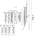
- Fig. 1 is a functional block diagram illustrating a configuration of an embodiment of the ultrasonic flaw detector according to the present invention.
- an object to be detected is a pipe 2, and an example will be described with reference to a case in which flaw detection using ultrasonic waves is conducted to a flaw portion of the pipe 2.
- the dotted line in Fig. 1 indicates the center of the pipe.
- the ultrasonic flaw detector of the present example is basically provided with an ultrasonic probe, and, in association with the ultrasonic probe, an ultrasonic transmitter/receiver and a drive element control unit for controlling a drive element, and a calculation unit for calculating control information of the drive element.
- an ultrasonic flaw detector 1 is generally composed of an ultrasonic probe 11, and, in association with the ultrasonic probe, an ultrasonic transmitter/receiver 12 for transmitting/receiving ultrasonic waves and a drive element control unit 13 for controlling a drive element, and a calculation unit 18 for calculating information for the drive element control unit 13 to control a drive element. Furthermore, as described later, the ultrasonic flaw detector 1 connected to the drive element control unit 13 is provided with a signal recording unit 14, an analysis unit 15, a display unit 16, and a design database 17.
- the ultrasonic probe 11 is a well-known ultrasonic probe that transmits/receives ultrasonic waves U.
- the ultrasonic probe 11 emits an ultrasonic wave U on the pipe 2 via acoustic coupling medium 3 by driving a plurality of ultrasonic elements, and receives a reflected ultrasonic wave from the pipe 2.
- the acoustic coupling medium 3 is a medium that is capable of propagating an ultrasonic wave, such as water, glycerin, machine oil, acrylic gel, or polystyrene gel, for example. Further, in the present embodiment, illustration of the acoustic coupling medium 3 may be sometimes omitted.
- the ultrasonic probe 11 has ultrasonic elements that are one-dimensionally arranged and is generally referred to as a linear array sensor.
- the ultrasonic probe 11 includes, for example, a mechanism for generating an ultrasonic wave, a damping material for damping an ultrasonic wave, and a front plate attached to a plane of oscillation of an ultrasonic wave.
- the mechanism for generating an ultrasonic wave is, for example, ceramics or ceramic composite materials, or a piezoelectric element that generates an ultrasonic wave by piezoelectric effect, or a piezoelectric element formed of a polymer film.
- the ultrasonic probe may be a 1.5-dimensional array sensor in which elements are unequally divided in the depth direction of a linear array sensor, a matrix array sensor in which elements are two-dimensionally arranged, or a ring array sensor in which ring-shaped elements are concentrically arranged.
- the ultrasonic probe may also be a divided ring array sensor in which the elements of a ring array sensor are divided in the circumferential direction, a random array sensor in which elements are randomly arranged, an arc array sensor in which elements are arranged at positions in the circumferential direction of an arc, a spherical array sensor in which elements are arranged on the surface of a sphere, or any other array sensor.
- the ultrasonic transmitter/receiver 12 is connected to the ultrasonic probe 11, and handles transmission/reception of an ultrasonic wave.
- the drive element control unit 13 controls an ultrasonic element that is to be actually driven at the ultrasonic transmitter/receiver 12 in response to drive control information for an ultrasonic element calculated by the calculation unit 18.
- the drive element control unit 13 includes a transmission/reception sensitivity adjustment unit 21, and a delay control unit 22, in which the transmission/reception sensitivity adjustment unit 21 adjusts transmission/reception sensitivity for an ultrasonic wave from the ultrasonic transmitter/receiver 12.
- the delay control unit 22 controls the oscillation of each of a plurality of ultrasonic elements according to a given time.
- the signal recording unit 14 stores a received signal (ultrasonic signal) received by the drive element control unit 13.
- the analysis unit 15 analyzes the received signal stored in the signal recording unit 14 and calculates a flaw detection result. Specifically, the analysis unit 15 calculates the flaw detection result based on the propagation path of an ultrasonic wave obtained on the basis of the surface information of the pipe 2 on which the ultrasonic wave is emitted. That is, the analysis unit 15 obtains the propagation path of the ultrasonic wave using a relative angle between the surface, of the pipe 2, at a position in which the ultrasonic wave is emitted and the ultrasonic probe 11.
- the display unit 16 displays the flaw detection result obtained by the analysis unit 15.
- the design database 17 that is connected to the analysis unit 15 stores in advance data on the surface shape of the pipe 2 at the stage of design.
- the ultrasonic flaw detector 1 is not limited to the configuration mentioned above as long as it adds delay time to the ultrasonic probe composed of a plurality of piezoelectric elements and controls the transmission/reception of ultrasonic waves. Moreover, a flaw detecting method of performing transmission/reception delay control of ultrasonic waves using a plurality of piezoelectric elements such as a phased array is well known, and hence, a detailed explanation thereof is omitted.
- a wedge When installing the ultrasonic probe 11, a wedge may be used to use an angle with a high degree of directivity.
- the wedge is an isotropic material that allows propagation of an ultrasonic wave and where acoustic impedance is grasped.
- the wedge is formed from acrylic, polyimide, gel or any other polymer materials, for example.
- damping materials may be arranged within and outside the wedge, a mountain-shaped wave-absorbing form may be provided, or a mechanism for multiple reflection reduction may be provided.
- Fig. 2 is an explanatory diagram showing an example of basic flaw detection
- Fig. 3 is an explanatory diagram showing an example of basic reconstruction of a flaw detection result.
- a plurality of ultrasonic elements provided to the ultrasonic probe 11 of the PA are given with appropriate delay time and are then oscillated. The direction and focal positions of the ultrasonic waves are thereby controlled.
- an ultrasonic wave U emitted into the pipe 2 is reflected and dispersed.
- the reflected ultrasonic wave is received by an ultrasonic element of the ultrasonic probe 11.
- the waveform of the received ultrasonic wave is imaged in the direction of the electronic scan according to an incident angle ⁇ and the refraction angle ⁇ of the ultrasonic wave which have been set.
- This imaging is generally referred to as B-scan or S-scan.
- B-scan This imaging is generally referred to as B-scan or S-scan.
- Fig. 3 an image is reconstructed based on the incident angle ⁇ and the refraction angle ⁇ that are according to the flaw detection conditions at the time of flaw detection.
- the B-scan will be is used.
- delay time is calculated according to flaw detection conditions such as the refraction angle ⁇ and the focal position on the pipe 2 (step S1). Then, the ultrasonic probe 11 is installed above the pipe 2, and scanning is started (step S2).
- Flaw detection is conducted on the pipe 2 according to the scanning (step S3), and data on the waveform of the ultrasonic wave obtained according to the flaw detection conditions such as the refraction angle ⁇ is reconstructed, and a B-scan is prepared (step S4). Thereafter, the scanning position of the pipe 2 is changed, and steps from the installation/operation step S2 to the reconstruction step S4 are repeated.
- the flaw detection step S3 and the reconstruction step S4 are performed under flaw detection conditions assuming a planarity condition in a case where there is a curved surface such as an undulation (a partial curve) due to excessive weld metal or grinding ( Fig. 5 ) or in a case the pipe 2 is not planar from the start, an ultrasonic wave does not enter at an intended angle. In addition, an error occurs in the detection result.
- Fig. 5 is an explanatory diagram of the flaw detection testing in which a curved surface 2a is formed on the surface of the pipe 2.
- the flaw detection is conducted with the incident angle ⁇ from any position of the ultrasonic probe 11. Therefore, if an ultrasonic wave is emitted on the surface of the pipe 2 having a curved surface 2a such as an undulation, the refraction angle ⁇ is not fixed due to Snell's law, and the propagation path of an ultrasonic wave varies depending on the incident position.
- the above process prevents not only the flaw detection with an intended ultrasonic wave, but also, depending on the incident angle ⁇ , the emission of an ultrasonic wave on the pipe 2. Further, in the case of evaluating a received ultrasonic signal, if reconstruction is conducted under the planarity condition without taking the surface shape of the pipe 2 into consideration, deviation from the actual propagation path of an ultrasonic wave will occur.
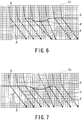
- Fig. 6 is an explanatory diagram of an ultrasonic wave propagation path where the flaw detection is conducted without taking the surface shape of the pipe 2 into consideration.
- Fig. 7 is an explanatory diagram of an ultrasonic wave propagation path where the flaw detection is conducted, taking the surface shape of the pipe 2 into consideration.
- ultrasonic waves U are transmitted under a condition assuming that the surface of the pipe 2 is a planar surface.
- the incident angles ⁇ are uniform, but the refraction angles ⁇ become non-uniform under the influence of the surface shape and the incident ultrasonic waves will follow paths different from the intended path.
- a flaw position obtained by the reconstruction will include an error with respect to the actual position of a flaw existing on the pipe 2, which will result in an error or overlooking in the evaluation of a flaw detection result.
- the surface shape of the pipe 2 is taken into consideration, and the delay time is controlled such that an ultrasonic wave enters a focal point F of the pipe 2.
- the combination of ultrasonic elements that are simultaneously used is decided in advance. These simultaneously driven elements move sequentially.
- the constants in the conditions for the flaw detection are the center position Ec of the simultaneously driven elements which are the starting points of the ultrasonic waves and the focal points F within the pipe 2 which are the goal points, and the parameters are incident points S.
- the refraction angles ⁇ are not necessarily uniform, and a general requirement for ultrasonic testing adopted by standards (such as JIS) that "flaw detection testing is conducted with uniform refraction angles ⁇ " is not satisfied. Furthermore, depending on the surface shape of the pipe 2, an element that may not properly emit an ultrasonic wave is possibly unavoidably used, and an ultrasonic wave of sufficient intensity may not be emitted.
- the ultrasonic flaw detector 1 of the present embodiment in consideration of the surface shape of the pipe 2, can suitably emit ultrasonic waves on the pipe 2 and also make the refraction angles ⁇ uniform.
- the ultrasonic flaw detector 1 conducts the flaw detection by calculating control information regarding an ultrasonic element by the calculation unit 18, and driving the ultrasonic element by the drive element control unit 13 based on the control information. Specifically, the incident points S and the focal points F are made constants based on the known surface shape of the pipe 2 and desired refraction angles ⁇ , and optimal ultrasonic elements are back calculated with the center position Ec of the simultaneously driven elements as a parameter.
- the ultrasonic flaw detector 1 uses the obtained ultrasonic elements and the performs the flaw detection by controlling the delay time of the ultrasonic elements. The ultrasonic flaw detector 1 can thereby always maintain uniform refraction angles ⁇ .
- Fig. 9 is a flow chart describing an overview of a flaw detecting method of the ultrasonic flaw detector 1 of the present embodiment.
- the ultrasonic probe 11 is installed above the pipe 2 and scanning is started (step S11), and the surface shape of the pipe 2 is measured using a shape measuring device (step S12).
- the surface shape may be obtained by measuring the as-built shape, or by importing the measurement data stored in the design database 17. The details of the shape acquisition step S12 will be described later.
- step S13 the delay control unit 22 calculates the optimal delay time for an ultrasonic element with respect to the surface shape, the ultrasonic probe 11 conducts the flaw detection on the pipe 2 (step S14), the ultrasonic data according to the surface shape is reconstructed, and a B-scan is generated (step S15).
- a method of calculating the position on a flaw detection result M from an ultrasonic signal Uj there are conceivable a method of calculating the position on a flaw detection result M from an ultrasonic signal Uj, and a method of calculating the position of an ultrasonic signal Uj corresponding to the coordinates from the coordinate points on the flaw detection result M.
- Fig. 10 is a flow chart describing a flaw detection condition setting process conducted by the ultrasonic flaw detector 1 of the present embodiment.
- Fig. 11 is an explanatory diagram showing a state of propagation of an ultrasonic wave in the pipe 2.
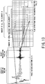
- Fig. 12 is an explanatory diagram of a case of the ultrasonic flaw detector 1 obtaining center coordinates Ec of simultaneously driven elements and the like.
- the focal point Fj is a focal point of an ultrasonic wave which has entered an assumed plane from the center coordinates Ec of the simultaneously driven elements at the incident angle ⁇ and refracted at the refraction angle ⁇ converging at a set depth.
- the surface shape coordinates where a straight line with the refraction angle ⁇ passing through the focal point Fj intersects with the surface shape function S is taken as Sj (incident point Sj).
- the inclination of the surface of the pipe 2 at the surface shape coordinates Sj (the relative angle between the ultrasonic probe 11 and the surface of the pipe 2) is taken as ⁇ j.
- the ultrasonic flaw detector 1 sets coordinates on the pipe surface (step S21). Specifically, the ultrasonic flaw detector 1 determines the element coordinates Ei of the ultrasonic probe 11, and determines a surface shape function S based on the measurement result or the design data of the surface shape of the pipe 2.
- the ultrasonic flaw detector 1 calculates the focal point Fj of the ultrasonic wave transmitted from the simultaneously driven elements with the center coordinates Ec, using the flaw detection conditions used in the linear scanning (normal linear scanning) that is conducted when the surface shape of the pipe 2 is assumed to be planar (step S22). More specifically, the ultrasonic flaw detector 1 transmits an ultrasonic wave from the center coordinates Ec at an incident angle ⁇ , causes the propagation inside the pipe 2 at a refraction angle ⁇ obtained when assuming that the ultrasonic wave entered the pipe 2 having a planar shape, and assumes that a point reached at a desired convergence depth of the ultrasonic wave as the focal point Fj.
- the ultrasonic flaw detector 1 calculates an incident point Sj that is according to the actual surface shape, using the refraction angle ⁇ and the focal point Fj (step S23). Specifically, the ultrasonic flaw detector 1 draws a straight line of the refraction angle ⁇ passing through the focal point Fj, and takes the point of intersection of the straight line and the surface shape function S as the incident point Sj. The ultrasonic flaw detector 1 further calculates an inclination ⁇ j at the incident point Sj (step S24). The calculation method of the inclination ⁇ j will be described later in detail.
- the ultrasonic flaw detector 1 calculates the actual incident angle ⁇ j (the incident angle taking the surface shape into consideration) by using Snell's law and by using the focal point Fj, the refraction angle ⁇ , the incident point Sj, and the inclination ⁇ j which have been calculated, and known sound speed values in the acoustic coupling medium 3 and the pipe 2 (step S25).
- the actual incident angle ⁇ j is a parameter in the ultrasonic flaw detecting method of the present embodiment.
- the ultrasonic flaw detector 1 calculates the actual center coordinates Ecj (the center coordinates of simultaneously driven elements taking the surface shape into consideration) using the incident point Sj and the incident angle ⁇ j (step S26). Specifically, the ultrasonic flaw detector 1 draws a straight line from the incident point Sj with an inclination of the angle ⁇ j, and assumes that the center coordinates Ec closest to the straight line as Ecj.
- the ultrasonic flaw detector 1 calculates by numerical calculation, for each of 'n' elements having the center coordinates Ecj as the center, the shortest distance between the element coordinates Ei and the focal point Fj through the surface shape function S.
- the ultrasonic flaw detector 1 obtains the propagation time of each ultrasonic wave from a known sound speed, and calculates the difference from the minimum value as the delay time of each element (step S27).
- the ultrasonic flaw detector 1 conducts the flaw detection using the calculated delay time and adds up the waveforms received by the elements while reflecting the delay time.
- the ultrasonic flaw detector 1 thereby obtains a phase matched waveform Uj(t) (step S28).
- the ultrasonic flaw detector 1 associates the phase matched waveform Uj(t) and position information regarding the pipe 2 using the center coordinates Ecj, the incident point Sj, the focal point Fj, the refraction angle ⁇ , the incident angle ⁇ j, and the sound speeds of the acoustic coupling medium 3 and the pipe 2 (flaw detection conditions) (step S29).
- the ultrasonic flaw detector 1 calculates the ultrasonic wave propagation time using the flaw detection conditions described above, and obtains the intensity of the phase matched waveform Um(t) corresponding to a flaw detection result reconstruction area M(x, z).
- the ultrasonic flaw detector 1 can obtain a flaw detection result which has been reconstructed by plotting the intensity of a waveform Um corresponding to the coordinates M.
- the ultrasonic flaw detector 1 scans the ultrasonic probe 11 and installs it at the next flaw detection position, repeats the coordinate setting step S21 to the associating step S29, and obtains a similar flaw detection result at the next flaw detection position.
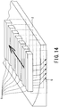
- Fig. 14 is an explanatory diagram of a case where the ultrasonic probe 11 performs scanning.
- the ultrasonic flaw detector 1 scans the ultrasonic probe 11 in a direction orthogonal to the direction of the lined up arrays.
- the ultrasonic flaw detector 1 can thereby obtain a three-dimensional flaw detection result.
- a similar result can be also obtained by conducting the scanning in a given direction in the case when other probes such as a matrix probe and a ring array probe are adopted.
- the inclination ⁇ j is a relative angle between the ultrasonic probe 11 and the surface of the pipe 2.
- the inclination ⁇ j at the incident point Sj of an ultrasonic wave is calculated from surface shape coordinates Sj-1 and Sj+1 adjacent to the incident point Sj.
- the inclination ⁇ j can also be calculated using surface shape coordinates Sj-a and Sj+a that are apart from the incident point Sj by 'a'.
- the inclination ⁇ j can also be calculated by using each point from the surface shape coordinates Sj-a to Sj+a and performing linear approximation by a method such as a least squares method so as to pass through each point.
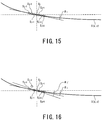
- Fig. 16 is another explanatory diagram of a case of obtaining the inclination ⁇ j of the surface of the pipe 2.
- the inclination ⁇ j may be calculated after removing data points that are highly deviated among a plurality of points from the surface shape coordinates Sj-a to Sj+a.
- the inclination ⁇ j at each position of the surface shape function S may be calculated first.
- the calculation is performed with respect to the center coordinates Ecj, the certain surface shape coordinates Sk, and the focal point Fj from coordinates S1 to coordinates Sn, according to Snell's law.
- a value with a minimum absolute value of the measurement result can be taken as the incident point Sj in the positional relationship of the center coordinates Ecj, the certain surface shape coordinates Sk, and the focal point Fj.
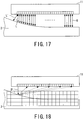
- Fig. 17 is an explanatory diagram of a method of measuring the surface shape function that uses a flight time method.
- Fig. 18 is an explanatory diagram of a method of measuring the surface shape function that uses aperture synthesis.
- the flight time method is a method of receiving an ultrasonic wave U transmitted from an ultrasonic element (element coordinates Ei) by the same ultrasonic element and reconstructing the shape of the surface of the pipe 2 from the propagation time of the received echo.
- a process of transmitting an ultrasonic wave U from an ultrasonic element (element coordinates Ei) and receiving the reflected wave by all the elements at element coordinates E1 to EN is performed.
- An element used for transmission is changed sequentially from the element coordinates E1 to EN, and the surface shape is measured using the measurement data.
- not all the pieces of the waveform data have to be used for the aperture synthesis process, and arbitrary data may be selected and be used for the process.
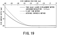
- Fig. 19 is a graph showing comparison between the surface shape functions obtained by the methods of Figs. 17 and 18 and a true value.
- the surface shape of the pipe 2 which is the true value was measured by a laser displacement meter. Measurement was performed with high accuracy by the aperture synthesis method, but it was found out that the error is great at the curvature portion according to the flight time method. This is because, with the flight time method, an echo is picked up whose propagation path is not the intended sound ray L but a shortest distance L'. Accordingly, the flight time method is not suitable for measurement of a complex surface shape.
- the flight time method is effective with an object with a small curvature or when grasping the relative position of the ultrasonic probe and the object, for example.
- Fig. 20 is a diagram showing a result of simulation performed under predetermined conditions for the intensity of an ultrasonic wave assuming that the surface shape is planar.
- Fig. 21 is a diagram showing a result of simulation performed under predetermined conditions for the intensity of an ultrasonic wave assuming that the surface shape is curved.
- the transmission delay conditions for the ultrasonic probe 11 are the refraction angle ⁇ of 45 degrees and the focal point forming position of 3/4t with respect to the thickness t of the pipe 2.
- Figs. 20 and 21 the intensity of an ultrasonic wave is shown based on sound field simulation for a case where the ultrasonic wave is emitted on the surface of the pipe 2 having a curved surface.
- the ultrasonic wave enters the pipe 2 from a part of a planar surface 2b of the surface of the pipe 2, it does not sufficiently enter from a curved surface 2a.
- the ultrasonic wave enters the pipe 2 also from the curved surface 2a.
- the ultrasonic flaw detector 1 can maintain the constant flaw detection conditions inside the pipe 2 by controlling, according to the surface shape of the pipe 2, the incident angle at each incident point such that the flaw detection conditions inside the pipe 2 are the same. Furthermore, the ultrasonic flaw detector 1 can emit the ultrasonic wave onto the curved surface 2a where flaw detection was not possible in Fig. 20 .
- Fig. 22 is a diagram showing a result of performing the reconstruction without taking the surface shape of the object into consideration.
- Fig. 23 is a diagram showing a result of performing the reconstruction, taking the surface shape of the object into consideration.
- the flaw detection is conducted under the condition that an ultrasonic wave is transmitted from a curved surface (an undulation) 33a on a flaw detection surface 33 of the object to a flaw 33b given to the object.
- the entire flaw 33b is the position where the influence of the curved surface 33a is exerted, but an indication of a corner echo 34 which is an echo from an opening of the flaw 33b occurring in a back surface 33c opposite the flaw detection surface 33 of the object is extended in an art shape. Furthermore, it can also be seen that a peak showing the corner echo 34 is positioned at an inner side than the surface of the back surface 33c. In addition, a tip echo 35 which is an echo from a tip of the flaw 33b on the inside of the object does not show a distinct peak. Furthermore, in Fig. 22 , there is a region showing an echo at a position where the flaw 33b does not exist (on the left side of the diagram).
- Fig. 23 the position of the corner echo 34 is clearer compared to Fig. 22 .
- the position of the peak is distinct for both the corner echo 34 and the tip echo 35, and the error in the position is greatly reduced.
- indications of the corner echo 34 and the tip echo 35 of the flaw 33b given to the inside of the object which receives the influence of the curved surface 33a are unclear, and also, the indication position of the flaw 33b includes an error with respect to the actual position of the flaw 33b.
- the ultrasonic flaw detector 1 of the present embodiment and the flaw detection method are capable of conducting accurate ultrasonic flaw detection by conducting flaw detection according to the surface shape of an object and reconstructing the flaw detection result according to the surface shape.
- the ultrasonic flaw detector 1 and the flaw detection method can thereby conduct the ultrasonic flaw detection with high detection accuracy on the surface of an object having a complex shape.
- a difference in sensitivity may occur depending on the surface shape of the object due to the angle of beam spread of the ultrasonic wave, the transmittance obtained based on the relation between the inclination ⁇ j and the incident angle ⁇ j, and the like. This means that the flaw detection accuracy varies depending on the influence of the surface shape of the object, and may lead to a significant measurement error.
- the ultrasonic flaw detector 1 and the flaw detection method of the present embodiment may perform calculation based on the surface shape of the object and the angle of beam spread of the ultrasonic wave and may maintain the intensity of the incident waves converging on the focal point to be constant.
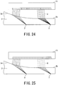
- Fig. 24 is an explanatory diagram representing a case where a difference in sensitivity arises due to a difference between surface shapes of the pipe 2.
- the intensity of an ultrasonic wave U entering the planar surface 2b of the pipe 2 is greater than that of an ultrasonic wave U entering the curved surface 2a, and the difference in the incident points on the curved surface 2a and the planar surface 2b results in the difference in the flaw detection accuracy.
- the gain of an ultrasonic wave oscillated from an ultrasonic element that is used is increased in advance for a surface shape with the lowest sensitivity, or by taking the surface shape with the lowest sensitivity in consideration, the gain of an ultrasonic wave entering a surface shape at which the sensitivity is not easily reduced is lowered in advance.
- Fig. 25 is an explanatory diagram of a case where the gain of the ultrasonic wave U is adjusted according to the surface shape of the pipe 2.
- the ultrasonic flaw detector 1 lowers, in advance, the gain of an ultrasonic wave U having an incident point being on the planar surface 2b with a high sensitivity.
- the intensity of the ultrasonic wave U inside the pipe 2 thereby becomes almost equal for the curved surface 2a and the planar surface 2b.
- the number of ultrasonic elements that are simultaneously driven is increased more than a normal case with respect to a surface shape with a lower sensitivity.
- Fig. 26 is an explanatory diagram of a case where the number of simultaneously driven elements is adjusted according to the surface shape of the pipe 2.
- the ultrasonic flaw detector 1 has increased the number 'n1' of the ultrasonic elements that oscillate the ultrasonic waves that are emitted on the curved surface 2a than the number 'n2' of the ultrasonic elements that oscillate the ultrasonic waves whose incident points are on the planar surface 2b.
- the intensity of the ultrasonic wave U inside the pipe 2 thereby becomes almost equal for the curved surface 2a and the planar surface 2b.
- the method of estimating the ultrasonic intensity at a focal point F may include a general ray tracing method, or other numerical analysis methods such as a difference method, a finite-element method, an FDTD method and a CIP method.
- the ultrasonic flaw detector 1 and the flaw detection method may be adopted with other flaw detecting methods such as sector scan, which scans the refraction angle fanwise, and Dynamic Depth Focusing (DDF), which changes the focal point depth according to an area to be measured.
- sector scan which scans the refraction angle fanwise
- DDF Dynamic Depth Focusing
- Fig. 27 is an explanatory diagram of a case where the sector scan is applied to ultrasonic flaw detection without taking the surface shape of the pipe 2 into consideration.
- Fig. 28 is an explanatory diagram of a case where the sector scan is applied to ultrasonic flaw detection, taking the surface shape of the pipe 2 into consideration.
- ultrasonic waves In the case the surface shape of the pipe 2 is planar, ultrasonic waves ideally enter the pipe 2 like the ultrasonic waves U1 shown by dotted lines in Fig. 27 . However, if the surface shape of the pipe 2 is curved, ultrasonic waves do not enter from intended positions, and the ultrasonic waves enter the pipe 2 like the ultrasonic waves U2 shown by solid lines in Fig. 27 . As a result, the flaw detection range will not take an ideal fan shape, and hence, the flaw detection cannot be conducted accurately.
- the ultrasonic flaw detector of the present embodiment and its method take the surface shape of the pipe 2 into consideration, and perform the back calculation of the simultaneously driven elements from the flaw detection range having an ideal fan shape of the ultrasonic waves U1 shown in Fig. 27 . It therefore becomes possible, as shown in Fig. 28 , to conduct the ideal flaw detection even if the surface shape is curved, as in a case where the surface shape is planar.
- analysis unit 15 and the calculation unit 18 can be realized, in each embodiment, by a processing unit, a memory, a program for causing these to operation, and the like. Accordingly, although the analysis unit 15 and the calculation unit 18 have been described as separate structural elements, they can also be integrated into one piece of hardware.
Landscapes
- Physics & Mathematics (AREA)
- Health & Medical Sciences (AREA)
- Life Sciences & Earth Sciences (AREA)
- Chemical & Material Sciences (AREA)
- Analytical Chemistry (AREA)
- Biochemistry (AREA)
- General Health & Medical Sciences (AREA)
- General Physics & Mathematics (AREA)
- Immunology (AREA)
- Pathology (AREA)
- Acoustics & Sound (AREA)
- Investigating Or Analyzing Materials By The Use Of Ultrasonic Waves (AREA)
Claims (7)
- Ultraschall-Defektdetektor (1) mit
einer Ultraschallsonde (11), die eine Mehrzahl von Ultraschallelementen umfasst und dazu ausgebildet ist, eine Ultraschallwelle (U) auf ein zu prüfendes Objekt (2) zu emittieren und eine von dem Objekt (2) reflektierte Ultraschallwelle zu empfangen;
einer Antriebselementsteuereinheit (13), die dazu ausgebildet ist, die Mehrzahl von Ultraschallelementen anzusteuern, um die Ultraschallwelle (U) auf das Objekt (2) zu emittieren und eine reflektierte Ultraschallwelle von dem Objekt (2) zu steuern;
einer Verzögerungssteuereinheit (22), die dazu ausgebildet ist, eine Oszillation jedes der Mehrzahl von Ultraschallelementen mit einer geeigneten Verzögerungszeit anzusteuern; und
einer Analyseeinheit (15), die dazu ausgebildet ist, das Empfangssignal der reflektierten Ultraschallwelle zu analysieren und ein Defektdetektionsergebnis zu berechnen,
einer Berechnungseinheit (18), die dazu ausgebildet ist,
einen Einfallswinkel (α) der Ultraschallwelle (U), die an einer Einfallsposition (S) eintritt, zu erhalten, indem sie einen Brechungswinkel (β) der auf das Objekt (2) einfallenden Ultraschallwelle (U), die Einfallsposition (S) der Ultraschallwelle (U) auf einer Oberfläche des Objekts (2) und eine Oberflächenform einer Oberfläche des Objekts (2) an der Einfallsposition (S) verwendet, und
auf die Mittellage (Ec) einer Mehrzahl von gleichzeitig angetriebenen Ultraschallelementen basierend auf der Einfallsposition (S) und dem Einfallswinkel (α) zurückzurechnen, wobei einheitliche Brechungswinkel (ß) beibehalten werden und die Einfallspositionen (S) und die Fokuspunkte (F) auf dem Objekt zu Konstanten gemacht werden, wobei
die Berechnungseinheit (18) ferner dazu ausgebildet ist, die Einfallsposition (S) basierend auf dem Brechungswinkel (β) und einem Fokuspunkt (F) der Ultraschallwelle (U) zu berechnen und zu erhalten, wenn das Ultraschallelement unter Defektdetektionsbedingungen angetrieben wird, um für das Objekt (2) mit einer planaren Oberflächenform verwendet zu werden. - Ultraschall-Defektdetektor (1) nach Anspruch 1, wobei die Oberflächenform eine Oberflächenneigung des Objekts (2) in Bezug auf die Ultraschallsonde (11) ist.
- Ultraschall-Defektdetektor (1) nach Anspruch 1, wobei die Antriebselementsteuereinheit (13) einen Elementsteuerabschnitt zum Steuern einer Verstärkung einer vom Ultraschallelement übertragenen Ultraschallwelle (U) gemäß der Oberflächenform aufweist.
- Ultraschall-Defektdetektor (1) nach Anspruch 1, wobei die Antriebselementsteuereinheit (13) einen Elementsteuerabschnitt zum Steuern der Anzahl der gleichzeitig angetriebenen Ultraschallelemente gemäß der Oberflächenform aufweist.
- Ultraschall-Defektdetektor (1) nach Anspruch 1, wobei die Antriebselementsteuereinheit (13) einen Elementsteuerabschnitt zum Steuern einer Verstärkung einer vom Ultraschallelement übertragenen Ultraschallwelle (U) gemäß der Oberflächenform und einen Elementsteuerabschnitt zum Steuern der Anzahl der gleichzeitig angetriebenen Ultraschallelemente gemäß der Oberflächenform aufweist.
- Ultraschall-Defektdetektor (1) nach Anspruch 1, ferner mit
einer Messeinheit, die dazu ausgebildet ist, die Oberflächenform des Objekts (2) basierend auf der emittierten Ultraschallwelle (U) und der reflektierten Ultraschallwelle zu messen. - Ultraschall-Defektdetektionsverfahren mit den Schritten:Emittieren einer Ultraschallwelle (U) auf ein zu prüfendes Objekt (2) durch Antreiben einer Mehrzahl von Ultraschallelementen und Empfangen einer von dem Objekt (2) reflektierten Ultraschallwelle;Steuern einer Oszillation eines jeden der Mehrzahl von Ultraschallelementen mit einer geeigneten Verzögerungszeit;Analysieren des Empfangssignals der reflektierten Ultraschallwelle und Berechnen eines Defektdetektionsergebnisses,Bestimmen eines Brechungswinkels (β) der in das Objekt (2) einfallenden Ultraschallwelle (U) und einer Einfallsposition (S) der Ultraschallwelle (U) auf einer Oberfläche des Objekts (2);Erfassen einer Oberflächenform einer Oberfläche des Objekts (2) an der Einfallsposition (S);Erhalten eines Einfallswinkels (α) der Ultraschallwelle (U), die an der Einfallsposition (S) eintritt, basierend auf dem Brechungswinkel (β), der Einfallsposition (S) und der Oberflächenform; undZurückrechnen auf die Mittellage (Ec) einer Mehrzahl von gleichzeitig angetriebenen Ultraschallelementen basierend auf der Einfallsposition (S) und dem Einfallswinkel (α) durch Aufrechterhalten einheitlicher Brechungswinkel (β) und Setzen von Einfallspunkten (S) und Brennpunkten (F) auf dem Objekt als Konstanten, wobeidie Einfallsposition (S) basierend auf dem Brechungswinkel (β) und einem Fokuspunkt (F) der Ultraschallwelle (U) berechnet und erhalten wird, wenn das Ultraschallelement unter Defektdetektionsbedingungen angetrieben wird, um für das Objekt (2) mit einer planaren Oberflächenform verwendet zu werden.
Applications Claiming Priority (1)
| Application Number | Priority Date | Filing Date | Title |
|---|---|---|---|
| JP2011157056 | 2011-07-15 |
Publications (3)
| Publication Number | Publication Date |
|---|---|
| EP2546641A2 EP2546641A2 (de) | 2013-01-16 |
| EP2546641A3 EP2546641A3 (de) | 2014-07-09 |
| EP2546641B1 true EP2546641B1 (de) | 2019-08-21 |
Family
ID=47010186
Family Applications (1)
| Application Number | Title | Priority Date | Filing Date |
|---|---|---|---|
| EP12176468.2A Active EP2546641B1 (de) | 2011-07-15 | 2012-07-13 | Ultraschalldefektdetektor und Ultraschalldefektdetektionsverfahren für Objekte mit komplexer Oberflächenform |
Country Status (4)
| Country | Link |
|---|---|
| US (1) | US9453819B2 (de) |
| EP (1) | EP2546641B1 (de) |
| JP (1) | JP5889742B2 (de) |
| ES (1) | ES2745122T3 (de) |
Families Citing this family (12)
| Publication number | Priority date | Publication date | Assignee | Title |
|---|---|---|---|---|
| JP6300225B2 (ja) * | 2013-12-03 | 2018-03-28 | 東芝エネルギーシステムズ株式会社 | タービン翼の検査装置及びその検査方法 |
| US9857311B2 (en) | 2014-08-27 | 2018-01-02 | Ge-Hitachi Nuclear Energy Americas Llc | Methods and systems for nondestructive testing with accurate position |
| JP6674263B2 (ja) * | 2016-01-22 | 2020-04-01 | 東芝テック株式会社 | 変状検出装置 |
| EP3447486B1 (de) * | 2017-08-25 | 2025-05-07 | Kabushiki Kaisha Toshiba | Vorrichtung für linear-scan-ultraschallinspektion und verfahren für linear-scan-ultraschallinspektion |
| JP6989416B2 (ja) * | 2017-08-25 | 2022-01-05 | 株式会社東芝 | リニアスキャン超音波探傷装置およびリニアスキャン超音波探傷方法 |
| CN108362776B (zh) * | 2018-01-26 | 2020-11-20 | 上海勘察设计研究院(集团)有限公司 | 一种多偏移距超声波映像检测方法 |
| JP6926011B2 (ja) | 2018-02-07 | 2021-08-25 | 株式会社東芝 | 超音波探傷装置および超音波探傷方法 |
| JP7233646B2 (ja) * | 2018-03-08 | 2023-03-07 | 三菱重工業株式会社 | 超音波検査方法、超音波検査装置およびプログラム |
| JP7006444B2 (ja) * | 2018-03-28 | 2022-01-24 | 日本製鉄株式会社 | 超音波探傷方法 |
| JP7109980B2 (ja) * | 2018-04-26 | 2022-08-01 | 株式会社東芝 | 超音波計測装置、超音波計測方法および部材の接合方法 |
| JP7159127B2 (ja) * | 2019-07-29 | 2022-10-24 | 日立Geニュークリア・エナジー株式会社 | 超音波探触子装置 |
| JP7199338B2 (ja) * | 2019-11-21 | 2023-01-05 | 株式会社東芝 | 処理装置、検査システム、処理方法、プログラム、及び記憶媒体 |
Family Cites Families (13)
| Publication number | Priority date | Publication date | Assignee | Title |
|---|---|---|---|---|
| DE2643918C3 (de) * | 1976-09-29 | 1986-10-23 | Siemens AG, 1000 Berlin und 8000 München | Gerät zur Ultraschallabtastung |
| JPS5837506B2 (ja) * | 1979-12-19 | 1983-08-16 | 株式会社日立製作所 | 超音波探傷装置 |
| US6200267B1 (en) * | 1998-05-13 | 2001-03-13 | Thomas Burke | High-speed ultrasound image improvement using an optical correlator |
| US6789427B2 (en) * | 2002-09-16 | 2004-09-14 | General Electric Company | Phased array ultrasonic inspection method for industrial applications |
| JP2006138672A (ja) * | 2004-11-10 | 2006-06-01 | Hitachi Ltd | 超音波検査方法及び装置 |
| DE102005043122A1 (de) * | 2005-09-10 | 2007-07-12 | Intelligendt Systems & Services Gmbh & Co Kg | Verfahren und Einrichtung zur Ultraschallprüfung eines Werkstückes mit einer unebenen Oberfläche |
| JP2006047328A (ja) * | 2005-10-24 | 2006-02-16 | Sumitomo Metal Ind Ltd | 超音波探傷方法 |
| JP4709640B2 (ja) * | 2005-12-19 | 2011-06-22 | 三菱重工業株式会社 | 超音波探傷方法及び装置 |
| JP4910770B2 (ja) * | 2007-02-28 | 2012-04-04 | Jfeスチール株式会社 | 管体の超音波探傷装置および超音波探傷方法 |
| JP5003275B2 (ja) * | 2007-05-17 | 2012-08-15 | Jfeスチール株式会社 | 管体の超音波探傷装置及び超音波探傷方法 |
| JP5155693B2 (ja) * | 2008-02-26 | 2013-03-06 | 東芝プラントシステム株式会社 | 超音波検査装置 |
| JP5155692B2 (ja) * | 2008-02-26 | 2013-03-06 | 東芝プラントシステム株式会社 | 超音波検査装置 |
| JP5306024B2 (ja) * | 2009-04-02 | 2013-10-02 | 株式会社東芝 | 超音波検査装置及び超音波検査方法 |
-
2012
- 2012-07-13 US US13/548,810 patent/US9453819B2/en active Active
- 2012-07-13 JP JP2012158056A patent/JP5889742B2/ja active Active
- 2012-07-13 ES ES12176468T patent/ES2745122T3/es active Active
- 2012-07-13 EP EP12176468.2A patent/EP2546641B1/de active Active
Non-Patent Citations (1)
| Title |
|---|
| None * |
Also Published As
| Publication number | Publication date |
|---|---|
| US9453819B2 (en) | 2016-09-27 |
| ES2745122T3 (es) | 2020-02-27 |
| EP2546641A2 (de) | 2013-01-16 |
| EP2546641A3 (de) | 2014-07-09 |
| US20130014587A1 (en) | 2013-01-17 |
| JP5889742B2 (ja) | 2016-03-22 |
| JP2013040924A (ja) | 2013-02-28 |
Similar Documents
| Publication | Publication Date | Title |
|---|---|---|
| EP2546641B1 (de) | Ultraschalldefektdetektor und Ultraschalldefektdetektionsverfahren für Objekte mit komplexer Oberflächenform | |
| KR101163549B1 (ko) | 위상배열 초음파 탐상용 기본 보정시험편 | |
| US8453509B2 (en) | Method for the non-destructive testing of a test object by way of ultrasound and apparatus therefor | |
| KR102121821B1 (ko) | 리니어 스캔 초음파 탐상 장치 및 리니어 스캔 초음파 탐상 방법 | |
| US7693251B2 (en) | Method and apparatus for ultrasonic inspection of reactor pressure vessel | |
| US20120024067A1 (en) | Method for the non-destructive testing of a test object by way of ultrasound and corresponding device | |
| JP5731765B2 (ja) | 超音波探傷装置および超音波探傷方法 | |
| KR101163554B1 (ko) | 위상배열 초음파 탐상용 검증용 시험편 | |
| US20090320601A1 (en) | Ultrasound Test Device with Array Test Probes | |
| JP2008122209A (ja) | 超音波探傷装置及び方法 | |
| CN101943680A (zh) | 一种带温度补偿的阵列超声探伤方法与系统 | |
| JP2012526975A (ja) | 超音波による非破壊検査用試験プローブ群と同様の試験プローブおよび試験装置 | |
| JP2013088240A (ja) | 超音波検査方法,超音波探傷方法及び超音波検査装置 | |
| KR101163551B1 (ko) | 위상배열 초음파 탐상용 감도보정 대비시험편 | |
| JP2013019715A (ja) | 超音波検査方法及び超音波検査装置 | |
| JP2008232627A (ja) | 超音波探傷装置および超音波探傷方法 | |
| JP2022070757A (ja) | 超音波探傷用プローブ配置の設計方法及びタービン翼の検査方法並びにプローブホルダ | |
| JP5959677B2 (ja) | 超音波探傷装置および超音波探傷方法 | |
| JP4112526B2 (ja) | 超音波探傷方法および装置 | |
| JP7629334B2 (ja) | 溶接部の超音波検査方法 | |
| JP3739368B2 (ja) | 超音波タンデムマルチアレイ探傷装置 | |
| KR101163552B1 (ko) | 위상배열 초음파 탐상용 스텐레스강/듀플렉스강용 감도보정 대비시험편 | |
| JP2013164361A (ja) | ガイド波を用いた非破壊検査方法 | |
| RU2695950C1 (ru) | Способ ультразвукового контроля дефектности металлических изделий | |
| CN120214101A (zh) | 奥氏体不锈钢焊缝缺陷的无损检测方法、系统和检测探头 |
Legal Events
| Date | Code | Title | Description |
|---|---|---|---|
| PUAI | Public reference made under article 153(3) epc to a published international application that has entered the european phase |
Free format text: ORIGINAL CODE: 0009012 |
|
| 17P | Request for examination filed |
Effective date: 20120713 |
|
| AK | Designated contracting states |
Kind code of ref document: A2 Designated state(s): AL AT BE BG CH CY CZ DE DK EE ES FI FR GB GR HR HU IE IS IT LI LT LU LV MC MK MT NL NO PL PT RO RS SE SI SK SM TR |
|
| AX | Request for extension of the european patent |
Extension state: BA ME |
|
| PUAL | Search report despatched |
Free format text: ORIGINAL CODE: 0009013 |
|
| AK | Designated contracting states |
Kind code of ref document: A3 Designated state(s): AL AT BE BG CH CY CZ DE DK EE ES FI FR GB GR HR HU IE IS IT LI LT LU LV MC MK MT NL NO PL PT RO RS SE SI SK SM TR |
|
| AX | Request for extension of the european patent |
Extension state: BA ME |
|
| RIC1 | Information provided on ipc code assigned before grant |
Ipc: G01N 29/26 20060101ALI20140602BHEP Ipc: G01N 29/04 20060101AFI20140602BHEP |
|
| STAA | Information on the status of an ep patent application or granted ep patent |
Free format text: STATUS: EXAMINATION IS IN PROGRESS |
|
| 17Q | First examination report despatched |
Effective date: 20170601 |
|
| GRAP | Despatch of communication of intention to grant a patent |
Free format text: ORIGINAL CODE: EPIDOSNIGR1 |
|
| STAA | Information on the status of an ep patent application or granted ep patent |
Free format text: STATUS: GRANT OF PATENT IS INTENDED |
|
| INTG | Intention to grant announced |
Effective date: 20190320 |
|
| GRAS | Grant fee paid |
Free format text: ORIGINAL CODE: EPIDOSNIGR3 |
|
| GRAA | (expected) grant |
Free format text: ORIGINAL CODE: 0009210 |
|
| STAA | Information on the status of an ep patent application or granted ep patent |
Free format text: STATUS: THE PATENT HAS BEEN GRANTED |
|
| AK | Designated contracting states |
Kind code of ref document: B1 Designated state(s): AL AT BE BG CH CY CZ DE DK EE ES FI FR GB GR HR HU IE IS IT LI LT LU LV MC MK MT NL NO PL PT RO RS SE SI SK SM TR |
|
| REG | Reference to a national code |
Ref country code: GB Ref legal event code: FG4D |
|
| REG | Reference to a national code |
Ref country code: CH Ref legal event code: EP |
|
| REG | Reference to a national code |
Ref country code: DE Ref legal event code: R096 Ref document number: 602012063089 Country of ref document: DE |
|
| REG | Reference to a national code |
Ref country code: AT Ref legal event code: REF Ref document number: 1170315 Country of ref document: AT Kind code of ref document: T Effective date: 20190915 |
|
| REG | Reference to a national code |
Ref country code: IE Ref legal event code: FG4D |
|
| REG | Reference to a national code |
Ref country code: SE Ref legal event code: TRGR |
|
| REG | Reference to a national code |
Ref country code: LT Ref legal event code: MG4D |
|
| REG | Reference to a national code |
Ref country code: NL Ref legal event code: MP Effective date: 20190821 |
|
| PG25 | Lapsed in a contracting state [announced via postgrant information from national office to epo] |
Ref country code: HR Free format text: LAPSE BECAUSE OF FAILURE TO SUBMIT A TRANSLATION OF THE DESCRIPTION OR TO PAY THE FEE WITHIN THE PRESCRIBED TIME-LIMIT Effective date: 20190821 Ref country code: NL Free format text: LAPSE BECAUSE OF FAILURE TO SUBMIT A TRANSLATION OF THE DESCRIPTION OR TO PAY THE FEE WITHIN THE PRESCRIBED TIME-LIMIT Effective date: 20190821 Ref country code: LT Free format text: LAPSE BECAUSE OF FAILURE TO SUBMIT A TRANSLATION OF THE DESCRIPTION OR TO PAY THE FEE WITHIN THE PRESCRIBED TIME-LIMIT Effective date: 20190821 Ref country code: NO Free format text: LAPSE BECAUSE OF FAILURE TO SUBMIT A TRANSLATION OF THE DESCRIPTION OR TO PAY THE FEE WITHIN THE PRESCRIBED TIME-LIMIT Effective date: 20191121 Ref country code: BG Free format text: LAPSE BECAUSE OF FAILURE TO SUBMIT A TRANSLATION OF THE DESCRIPTION OR TO PAY THE FEE WITHIN THE PRESCRIBED TIME-LIMIT Effective date: 20191121 Ref country code: PT Free format text: LAPSE BECAUSE OF FAILURE TO SUBMIT A TRANSLATION OF THE DESCRIPTION OR TO PAY THE FEE WITHIN THE PRESCRIBED TIME-LIMIT Effective date: 20191223 |
|
| REG | Reference to a national code |
Ref country code: ES Ref legal event code: FG2A Ref document number: 2745122 Country of ref document: ES Kind code of ref document: T3 Effective date: 20200227 |
|
| PG25 | Lapsed in a contracting state [announced via postgrant information from national office to epo] |
Ref country code: IS Free format text: LAPSE BECAUSE OF FAILURE TO SUBMIT A TRANSLATION OF THE DESCRIPTION OR TO PAY THE FEE WITHIN THE PRESCRIBED TIME-LIMIT Effective date: 20191221 Ref country code: GR Free format text: LAPSE BECAUSE OF FAILURE TO SUBMIT A TRANSLATION OF THE DESCRIPTION OR TO PAY THE FEE WITHIN THE PRESCRIBED TIME-LIMIT Effective date: 20191122 Ref country code: RS Free format text: LAPSE BECAUSE OF FAILURE TO SUBMIT A TRANSLATION OF THE DESCRIPTION OR TO PAY THE FEE WITHIN THE PRESCRIBED TIME-LIMIT Effective date: 20190821 Ref country code: AL Free format text: LAPSE BECAUSE OF FAILURE TO SUBMIT A TRANSLATION OF THE DESCRIPTION OR TO PAY THE FEE WITHIN THE PRESCRIBED TIME-LIMIT Effective date: 20190821 Ref country code: LV Free format text: LAPSE BECAUSE OF FAILURE TO SUBMIT A TRANSLATION OF THE DESCRIPTION OR TO PAY THE FEE WITHIN THE PRESCRIBED TIME-LIMIT Effective date: 20190821 |
|
| REG | Reference to a national code |
Ref country code: AT Ref legal event code: MK05 Ref document number: 1170315 Country of ref document: AT Kind code of ref document: T Effective date: 20190821 |
|
| PG25 | Lapsed in a contracting state [announced via postgrant information from national office to epo] |
Ref country code: TR Free format text: LAPSE BECAUSE OF FAILURE TO SUBMIT A TRANSLATION OF THE DESCRIPTION OR TO PAY THE FEE WITHIN THE PRESCRIBED TIME-LIMIT Effective date: 20190821 |
|
| PG25 | Lapsed in a contracting state [announced via postgrant information from national office to epo] |
Ref country code: RO Free format text: LAPSE BECAUSE OF FAILURE TO SUBMIT A TRANSLATION OF THE DESCRIPTION OR TO PAY THE FEE WITHIN THE PRESCRIBED TIME-LIMIT Effective date: 20190821 Ref country code: IT Free format text: LAPSE BECAUSE OF FAILURE TO SUBMIT A TRANSLATION OF THE DESCRIPTION OR TO PAY THE FEE WITHIN THE PRESCRIBED TIME-LIMIT Effective date: 20190821 Ref country code: DK Free format text: LAPSE BECAUSE OF FAILURE TO SUBMIT A TRANSLATION OF THE DESCRIPTION OR TO PAY THE FEE WITHIN THE PRESCRIBED TIME-LIMIT Effective date: 20190821 Ref country code: EE Free format text: LAPSE BECAUSE OF FAILURE TO SUBMIT A TRANSLATION OF THE DESCRIPTION OR TO PAY THE FEE WITHIN THE PRESCRIBED TIME-LIMIT Effective date: 20190821 Ref country code: AT Free format text: LAPSE BECAUSE OF FAILURE TO SUBMIT A TRANSLATION OF THE DESCRIPTION OR TO PAY THE FEE WITHIN THE PRESCRIBED TIME-LIMIT Effective date: 20190821 Ref country code: PL Free format text: LAPSE BECAUSE OF FAILURE TO SUBMIT A TRANSLATION OF THE DESCRIPTION OR TO PAY THE FEE WITHIN THE PRESCRIBED TIME-LIMIT Effective date: 20190821 |
|
| PG25 | Lapsed in a contracting state [announced via postgrant information from national office to epo] |
Ref country code: IS Free format text: LAPSE BECAUSE OF FAILURE TO SUBMIT A TRANSLATION OF THE DESCRIPTION OR TO PAY THE FEE WITHIN THE PRESCRIBED TIME-LIMIT Effective date: 20200224 Ref country code: SK Free format text: LAPSE BECAUSE OF FAILURE TO SUBMIT A TRANSLATION OF THE DESCRIPTION OR TO PAY THE FEE WITHIN THE PRESCRIBED TIME-LIMIT Effective date: 20190821 Ref country code: SM Free format text: LAPSE BECAUSE OF FAILURE TO SUBMIT A TRANSLATION OF THE DESCRIPTION OR TO PAY THE FEE WITHIN THE PRESCRIBED TIME-LIMIT Effective date: 20190821 Ref country code: CZ Free format text: LAPSE BECAUSE OF FAILURE TO SUBMIT A TRANSLATION OF THE DESCRIPTION OR TO PAY THE FEE WITHIN THE PRESCRIBED TIME-LIMIT Effective date: 20190821 |
|
| REG | Reference to a national code |
Ref country code: DE Ref legal event code: R097 Ref document number: 602012063089 Country of ref document: DE |
|
| PLBE | No opposition filed within time limit |
Free format text: ORIGINAL CODE: 0009261 |
|
| STAA | Information on the status of an ep patent application or granted ep patent |
Free format text: STATUS: NO OPPOSITION FILED WITHIN TIME LIMIT |
|
| PG2D | Information on lapse in contracting state deleted |
Ref country code: IS |
|
| 26N | No opposition filed |
Effective date: 20200603 |
|
| PG25 | Lapsed in a contracting state [announced via postgrant information from national office to epo] |
Ref country code: SI Free format text: LAPSE BECAUSE OF FAILURE TO SUBMIT A TRANSLATION OF THE DESCRIPTION OR TO PAY THE FEE WITHIN THE PRESCRIBED TIME-LIMIT Effective date: 20190821 |
|
| PG25 | Lapsed in a contracting state [announced via postgrant information from national office to epo] |
Ref country code: MC Free format text: LAPSE BECAUSE OF FAILURE TO SUBMIT A TRANSLATION OF THE DESCRIPTION OR TO PAY THE FEE WITHIN THE PRESCRIBED TIME-LIMIT Effective date: 20190821 |
|
| REG | Reference to a national code |
Ref country code: CH Ref legal event code: PL |
|
| PG25 | Lapsed in a contracting state [announced via postgrant information from national office to epo] |
Ref country code: CH Free format text: LAPSE BECAUSE OF NON-PAYMENT OF DUE FEES Effective date: 20200731 Ref country code: LI Free format text: LAPSE BECAUSE OF NON-PAYMENT OF DUE FEES Effective date: 20200731 Ref country code: LU Free format text: LAPSE BECAUSE OF NON-PAYMENT OF DUE FEES Effective date: 20200713 |
|
| PG25 | Lapsed in a contracting state [announced via postgrant information from national office to epo] |
Ref country code: IE Free format text: LAPSE BECAUSE OF NON-PAYMENT OF DUE FEES Effective date: 20200713 |
|
| PG25 | Lapsed in a contracting state [announced via postgrant information from national office to epo] |
Ref country code: MT Free format text: LAPSE BECAUSE OF FAILURE TO SUBMIT A TRANSLATION OF THE DESCRIPTION OR TO PAY THE FEE WITHIN THE PRESCRIBED TIME-LIMIT Effective date: 20190821 Ref country code: CY Free format text: LAPSE BECAUSE OF FAILURE TO SUBMIT A TRANSLATION OF THE DESCRIPTION OR TO PAY THE FEE WITHIN THE PRESCRIBED TIME-LIMIT Effective date: 20190821 |
|
| PG25 | Lapsed in a contracting state [announced via postgrant information from national office to epo] |
Ref country code: MK Free format text: LAPSE BECAUSE OF FAILURE TO SUBMIT A TRANSLATION OF THE DESCRIPTION OR TO PAY THE FEE WITHIN THE PRESCRIBED TIME-LIMIT Effective date: 20190821 |
|
| PGFP | Annual fee paid to national office [announced via postgrant information from national office to epo] |
Ref country code: GB Payment date: 20250522 Year of fee payment: 14 |
|
| PGFP | Annual fee paid to national office [announced via postgrant information from national office to epo] |
Ref country code: BE Payment date: 20250619 Year of fee payment: 14 |
|
| PGFP | Annual fee paid to national office [announced via postgrant information from national office to epo] |
Ref country code: FR Payment date: 20250523 Year of fee payment: 14 |
|
| PGFP | Annual fee paid to national office [announced via postgrant information from national office to epo] |
Ref country code: SE Payment date: 20250528 Year of fee payment: 14 |
|
| PGFP | Annual fee paid to national office [announced via postgrant information from national office to epo] |
Ref country code: ES Payment date: 20250804 Year of fee payment: 14 Ref country code: FI Payment date: 20250715 Year of fee payment: 14 |
|
| PGFP | Annual fee paid to national office [announced via postgrant information from national office to epo] |
Ref country code: DE Payment date: 20250528 Year of fee payment: 14 |