EP2546641B1 - Ultrasonic flaw detector and ultrasonic flaw detection method for objects having a complex surface shape - Google Patents
Ultrasonic flaw detector and ultrasonic flaw detection method for objects having a complex surface shape Download PDFInfo
- Publication number
- EP2546641B1 EP2546641B1 EP12176468.2A EP12176468A EP2546641B1 EP 2546641 B1 EP2546641 B1 EP 2546641B1 EP 12176468 A EP12176468 A EP 12176468A EP 2546641 B1 EP2546641 B1 EP 2546641B1
- Authority
- EP
- European Patent Office
- Prior art keywords
- ultrasonic
- ultrasonic wave
- surface shape
- incident
- flaw detection
- Prior art date
- Legal status (The legal status is an assumption and is not a legal conclusion. Google has not performed a legal analysis and makes no representation as to the accuracy of the status listed.)
- Active
Links
- 238000001514 detection method Methods 0.000 title claims description 101
- 238000000034 method Methods 0.000 claims description 57
- 239000000523 sample Substances 0.000 claims description 41
- 238000004364 calculation method Methods 0.000 claims description 15
- 238000004458 analytical method Methods 0.000 claims description 13
- 238000005259 measurement Methods 0.000 claims description 10
- 230000010355 oscillation Effects 0.000 claims description 4
- 238000010586 diagram Methods 0.000 description 47
- 230000006870 function Effects 0.000 description 16
- 238000012360 testing method Methods 0.000 description 12
- 230000035945 sensitivity Effects 0.000 description 11
- 230000005540 biological transmission Effects 0.000 description 10
- 230000008569 process Effects 0.000 description 9
- 238000005516 engineering process Methods 0.000 description 7
- 230000008878 coupling Effects 0.000 description 5
- 238000010168 coupling process Methods 0.000 description 5
- 238000005859 coupling reaction Methods 0.000 description 5
- 238000013461 design Methods 0.000 description 5
- 238000004088 simulation Methods 0.000 description 5
- 230000015572 biosynthetic process Effects 0.000 description 3
- 238000013016 damping Methods 0.000 description 3
- 239000000463 material Substances 0.000 description 3
- 239000011159 matrix material Substances 0.000 description 3
- 230000007246 mechanism Effects 0.000 description 3
- 238000001308 synthesis method Methods 0.000 description 3
- 238000003786 synthesis reaction Methods 0.000 description 3
- PEDCQBHIVMGVHV-UHFFFAOYSA-N Glycerine Chemical compound OCC(O)CO PEDCQBHIVMGVHV-UHFFFAOYSA-N 0.000 description 2
- NIXOWILDQLNWCW-UHFFFAOYSA-N acrylic acid group Chemical group C(C=C)(=O)O NIXOWILDQLNWCW-UHFFFAOYSA-N 0.000 description 2
- 230000003044 adaptive effect Effects 0.000 description 2
- 238000003491 array Methods 0.000 description 2
- 239000000919 ceramic Substances 0.000 description 2
- 230000001066 destructive effect Effects 0.000 description 2
- 238000009434 installation Methods 0.000 description 2
- 239000002184 metal Substances 0.000 description 2
- 238000012545 processing Methods 0.000 description 2
- 239000004642 Polyimide Substances 0.000 description 1
- 239000004793 Polystyrene Substances 0.000 description 1
- 239000002131 composite material Substances 0.000 description 1
- 238000010276 construction Methods 0.000 description 1
- 239000004035 construction material Substances 0.000 description 1
- 238000012937 correction Methods 0.000 description 1
- 238000006073 displacement reaction Methods 0.000 description 1
- 238000002592 echocardiography Methods 0.000 description 1
- 230000000694 effects Effects 0.000 description 1
- 238000011156 evaluation Methods 0.000 description 1
- 235000011187 glycerol Nutrition 0.000 description 1
- 238000003384 imaging method Methods 0.000 description 1
- 239000010721 machine oil Substances 0.000 description 1
- 238000005457 optimization Methods 0.000 description 1
- 229920001721 polyimide Polymers 0.000 description 1
- 229920006254 polymer film Polymers 0.000 description 1
- 239000002861 polymer material Substances 0.000 description 1
- 229920002223 polystyrene Polymers 0.000 description 1
- 230000001902 propagating effect Effects 0.000 description 1
- 230000009467 reduction Effects 0.000 description 1
- 230000004044 response Effects 0.000 description 1
- 238000002834 transmittance Methods 0.000 description 1
- XLYOFNOQVPJJNP-UHFFFAOYSA-N water Substances O XLYOFNOQVPJJNP-UHFFFAOYSA-N 0.000 description 1
- 238000003466 welding Methods 0.000 description 1
Images


Classifications
-
- G—PHYSICS
- G01—MEASURING; TESTING
- G01N—INVESTIGATING OR ANALYSING MATERIALS BY DETERMINING THEIR CHEMICAL OR PHYSICAL PROPERTIES
- G01N29/00—Investigating or analysing materials by the use of ultrasonic, sonic or infrasonic waves; Visualisation of the interior of objects by transmitting ultrasonic or sonic waves through the object
- G01N29/04—Analysing solids
- G01N29/043—Analysing solids in the interior, e.g. by shear waves
-
- G—PHYSICS
- G01—MEASURING; TESTING
- G01N—INVESTIGATING OR ANALYSING MATERIALS BY DETERMINING THEIR CHEMICAL OR PHYSICAL PROPERTIES
- G01N29/00—Investigating or analysing materials by the use of ultrasonic, sonic or infrasonic waves; Visualisation of the interior of objects by transmitting ultrasonic or sonic waves through the object
- G01N29/22—Details, e.g. general constructional or apparatus details
- G01N29/26—Arrangements for orientation or scanning by relative movement of the head and the sensor
- G01N29/262—Arrangements for orientation or scanning by relative movement of the head and the sensor by electronic orientation or focusing, e.g. with phased arrays
-
- G—PHYSICS
- G01—MEASURING; TESTING
- G01N—INVESTIGATING OR ANALYSING MATERIALS BY DETERMINING THEIR CHEMICAL OR PHYSICAL PROPERTIES
- G01N2291/00—Indexing codes associated with group G01N29/00
- G01N2291/04—Wave modes and trajectories
- G01N2291/056—Angular incidence, angular propagation
-
- G—PHYSICS
- G01—MEASURING; TESTING
- G01N—INVESTIGATING OR ANALYSING MATERIALS BY DETERMINING THEIR CHEMICAL OR PHYSICAL PROPERTIES
- G01N2291/00—Indexing codes associated with group G01N29/00
- G01N2291/26—Scanned objects
- G01N2291/263—Surfaces
- G01N2291/2638—Complex surfaces
Definitions
- the present invention relates to an ultrasonic flaw detector and an ultrasonic flaw detecting method.
- Ultrasonic flaw detection testing is a non-destructive technology that enables checking of the soundness of the surface and the inside of a construction material, and is a testing technology indispensable in various fields. Especially, in recent years, there is a demand for testing of a construction having a complex surface shape such as a curved surface, and the technological demand regarding ultrasonic flaw detection is becoming higher.
- an ultrasonic wave cannot be appropriately emitted on the object.
- a portion which is designed to be planar unintentionally becomes non-planar due to a strain or chevron-like deformation caused by welding heat input or a convex shape formed after molten metal is poured.
- various piping structures typified by a nozzle stub of, for example, a nuclear power plant or a thermal power plant, or a platform region of a turbine blade is designed to have a complex shape, and even if constructed as designed, testing thereof is difficult. If such object is taken as the object of the ultrasonic flaw detection testing, an ultrasonic wave cannot be emitted on the object or, even if the ultrasonic wave is emitted, a desired refraction angle may not be obtained.
- a phased array is a technology of forming a given waveform by arranging small ultrasonic sensors, and varying the timing (delay time) of the sensors and emitting ultrasonic waves.
- the phased array can possibly cope with a complex shape.
- the delay time reflecting the shape has to be calculated for each target.
- the value of the shape to be reflected should include not only the values on a drawing, but also the as-built values (a drawing created based on existing conditions and analysis data). Accordingly, to carry out ultrasonic flaw detection on a complex-shaped region, a technology for measuring the surface shape of a target with high accuracy is needed, as well as a technology for controlling ultrasonic waves (calculating the delay time) according to the curvature.
- Patent Document 1 Japanese Patent Laid-Open No. 2007-170877 : Patent Document 1
- Patent Document 1 only describes optimization of delay time conditions according to the surface shape of an object. Therefore, when using an electronic scan, which, typified by a linear scan, sequentially moves elements to be used, elements to be used are fixed with respect to a focal point, and thus, there arises a problem that an ultrasonic wave enters from an unintended incident point. There is also provided a problem of an ultrasonic wave not reaching a test portion due to use of an element at a blind angle.
- emitting an ultrasonic wave according to the surface shape allows to cope with the problem of the incident angle of the ultrasonic wave changing.
- a flaw indication echo is displayed at a portion different from the actual detection position in a flaw detection result that is displayed in a case if analysis has been performed without taking the influence of the surface shape into consideration.
- the position of an indication echo cannot be accurately identified unless the flaw detection result is separately corrected in consideration of the influence of the surface shape, and an error occurs in the detection position. That is, the flaw detection accuracy is greatly reduced. It is also conceivable that an indication echo is extended and is displayed with a shape different from the actual flaw. This can be overcome if an inspector corrects the detection position error by hand calculation while taking the influence of the surface shape into consideration. But this will increase the burden on the inspector. In addition, if the surface shape is complex, correction will require much skill.
- JP 2006 047328 A for detecting fine flaws.
- the present invention has been made in view of the above circumstances, and an object thereof is to provide an ultrasonic flaw detector and a method thereof, which are capable of achieving high detecting accuracy regardless of the surface shape of an object.
- ultrasonic flaw detection and the method thereof can achieve high detection accuracy regardless of the surface shape of an object to be inspected.
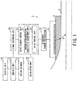
- Fig. 1 is a functional block diagram illustrating a configuration of an embodiment of the ultrasonic flaw detector according to the present invention.
- an object to be detected is a pipe 2, and an example will be described with reference to a case in which flaw detection using ultrasonic waves is conducted to a flaw portion of the pipe 2.
- the dotted line in Fig. 1 indicates the center of the pipe.
- the ultrasonic flaw detector of the present example is basically provided with an ultrasonic probe, and, in association with the ultrasonic probe, an ultrasonic transmitter/receiver and a drive element control unit for controlling a drive element, and a calculation unit for calculating control information of the drive element.
- an ultrasonic flaw detector 1 is generally composed of an ultrasonic probe 11, and, in association with the ultrasonic probe, an ultrasonic transmitter/receiver 12 for transmitting/receiving ultrasonic waves and a drive element control unit 13 for controlling a drive element, and a calculation unit 18 for calculating information for the drive element control unit 13 to control a drive element. Furthermore, as described later, the ultrasonic flaw detector 1 connected to the drive element control unit 13 is provided with a signal recording unit 14, an analysis unit 15, a display unit 16, and a design database 17.
- the ultrasonic probe 11 is a well-known ultrasonic probe that transmits/receives ultrasonic waves U.
- the ultrasonic probe 11 emits an ultrasonic wave U on the pipe 2 via acoustic coupling medium 3 by driving a plurality of ultrasonic elements, and receives a reflected ultrasonic wave from the pipe 2.
- the acoustic coupling medium 3 is a medium that is capable of propagating an ultrasonic wave, such as water, glycerin, machine oil, acrylic gel, or polystyrene gel, for example. Further, in the present embodiment, illustration of the acoustic coupling medium 3 may be sometimes omitted.
- the ultrasonic probe 11 has ultrasonic elements that are one-dimensionally arranged and is generally referred to as a linear array sensor.
- the ultrasonic probe 11 includes, for example, a mechanism for generating an ultrasonic wave, a damping material for damping an ultrasonic wave, and a front plate attached to a plane of oscillation of an ultrasonic wave.
- the mechanism for generating an ultrasonic wave is, for example, ceramics or ceramic composite materials, or a piezoelectric element that generates an ultrasonic wave by piezoelectric effect, or a piezoelectric element formed of a polymer film.
- the ultrasonic probe may be a 1.5-dimensional array sensor in which elements are unequally divided in the depth direction of a linear array sensor, a matrix array sensor in which elements are two-dimensionally arranged, or a ring array sensor in which ring-shaped elements are concentrically arranged.
- the ultrasonic probe may also be a divided ring array sensor in which the elements of a ring array sensor are divided in the circumferential direction, a random array sensor in which elements are randomly arranged, an arc array sensor in which elements are arranged at positions in the circumferential direction of an arc, a spherical array sensor in which elements are arranged on the surface of a sphere, or any other array sensor.
- the ultrasonic transmitter/receiver 12 is connected to the ultrasonic probe 11, and handles transmission/reception of an ultrasonic wave.
- the drive element control unit 13 controls an ultrasonic element that is to be actually driven at the ultrasonic transmitter/receiver 12 in response to drive control information for an ultrasonic element calculated by the calculation unit 18.
- the drive element control unit 13 includes a transmission/reception sensitivity adjustment unit 21, and a delay control unit 22, in which the transmission/reception sensitivity adjustment unit 21 adjusts transmission/reception sensitivity for an ultrasonic wave from the ultrasonic transmitter/receiver 12.
- the delay control unit 22 controls the oscillation of each of a plurality of ultrasonic elements according to a given time.
- the signal recording unit 14 stores a received signal (ultrasonic signal) received by the drive element control unit 13.
- the analysis unit 15 analyzes the received signal stored in the signal recording unit 14 and calculates a flaw detection result. Specifically, the analysis unit 15 calculates the flaw detection result based on the propagation path of an ultrasonic wave obtained on the basis of the surface information of the pipe 2 on which the ultrasonic wave is emitted. That is, the analysis unit 15 obtains the propagation path of the ultrasonic wave using a relative angle between the surface, of the pipe 2, at a position in which the ultrasonic wave is emitted and the ultrasonic probe 11.
- the display unit 16 displays the flaw detection result obtained by the analysis unit 15.
- the design database 17 that is connected to the analysis unit 15 stores in advance data on the surface shape of the pipe 2 at the stage of design.
- the ultrasonic flaw detector 1 is not limited to the configuration mentioned above as long as it adds delay time to the ultrasonic probe composed of a plurality of piezoelectric elements and controls the transmission/reception of ultrasonic waves. Moreover, a flaw detecting method of performing transmission/reception delay control of ultrasonic waves using a plurality of piezoelectric elements such as a phased array is well known, and hence, a detailed explanation thereof is omitted.
- a wedge When installing the ultrasonic probe 11, a wedge may be used to use an angle with a high degree of directivity.
- the wedge is an isotropic material that allows propagation of an ultrasonic wave and where acoustic impedance is grasped.
- the wedge is formed from acrylic, polyimide, gel or any other polymer materials, for example.
- damping materials may be arranged within and outside the wedge, a mountain-shaped wave-absorbing form may be provided, or a mechanism for multiple reflection reduction may be provided.
- Fig. 2 is an explanatory diagram showing an example of basic flaw detection
- Fig. 3 is an explanatory diagram showing an example of basic reconstruction of a flaw detection result.
- a plurality of ultrasonic elements provided to the ultrasonic probe 11 of the PA are given with appropriate delay time and are then oscillated. The direction and focal positions of the ultrasonic waves are thereby controlled.
- an ultrasonic wave U emitted into the pipe 2 is reflected and dispersed.
- the reflected ultrasonic wave is received by an ultrasonic element of the ultrasonic probe 11.
- the waveform of the received ultrasonic wave is imaged in the direction of the electronic scan according to an incident angle ⁇ and the refraction angle ⁇ of the ultrasonic wave which have been set.
- This imaging is generally referred to as B-scan or S-scan.
- B-scan This imaging is generally referred to as B-scan or S-scan.
- Fig. 3 an image is reconstructed based on the incident angle ⁇ and the refraction angle ⁇ that are according to the flaw detection conditions at the time of flaw detection.
- the B-scan will be is used.
- delay time is calculated according to flaw detection conditions such as the refraction angle ⁇ and the focal position on the pipe 2 (step S1). Then, the ultrasonic probe 11 is installed above the pipe 2, and scanning is started (step S2).
- Flaw detection is conducted on the pipe 2 according to the scanning (step S3), and data on the waveform of the ultrasonic wave obtained according to the flaw detection conditions such as the refraction angle ⁇ is reconstructed, and a B-scan is prepared (step S4). Thereafter, the scanning position of the pipe 2 is changed, and steps from the installation/operation step S2 to the reconstruction step S4 are repeated.
- the flaw detection step S3 and the reconstruction step S4 are performed under flaw detection conditions assuming a planarity condition in a case where there is a curved surface such as an undulation (a partial curve) due to excessive weld metal or grinding ( Fig. 5 ) or in a case the pipe 2 is not planar from the start, an ultrasonic wave does not enter at an intended angle. In addition, an error occurs in the detection result.
- Fig. 5 is an explanatory diagram of the flaw detection testing in which a curved surface 2a is formed on the surface of the pipe 2.
- the flaw detection is conducted with the incident angle ⁇ from any position of the ultrasonic probe 11. Therefore, if an ultrasonic wave is emitted on the surface of the pipe 2 having a curved surface 2a such as an undulation, the refraction angle ⁇ is not fixed due to Snell's law, and the propagation path of an ultrasonic wave varies depending on the incident position.
- the above process prevents not only the flaw detection with an intended ultrasonic wave, but also, depending on the incident angle ⁇ , the emission of an ultrasonic wave on the pipe 2. Further, in the case of evaluating a received ultrasonic signal, if reconstruction is conducted under the planarity condition without taking the surface shape of the pipe 2 into consideration, deviation from the actual propagation path of an ultrasonic wave will occur.
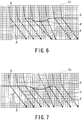
- Fig. 6 is an explanatory diagram of an ultrasonic wave propagation path where the flaw detection is conducted without taking the surface shape of the pipe 2 into consideration.
- Fig. 7 is an explanatory diagram of an ultrasonic wave propagation path where the flaw detection is conducted, taking the surface shape of the pipe 2 into consideration.
- ultrasonic waves U are transmitted under a condition assuming that the surface of the pipe 2 is a planar surface.
- the incident angles ⁇ are uniform, but the refraction angles ⁇ become non-uniform under the influence of the surface shape and the incident ultrasonic waves will follow paths different from the intended path.
- a flaw position obtained by the reconstruction will include an error with respect to the actual position of a flaw existing on the pipe 2, which will result in an error or overlooking in the evaluation of a flaw detection result.
- the surface shape of the pipe 2 is taken into consideration, and the delay time is controlled such that an ultrasonic wave enters a focal point F of the pipe 2.
- the combination of ultrasonic elements that are simultaneously used is decided in advance. These simultaneously driven elements move sequentially.
- the constants in the conditions for the flaw detection are the center position Ec of the simultaneously driven elements which are the starting points of the ultrasonic waves and the focal points F within the pipe 2 which are the goal points, and the parameters are incident points S.
- the refraction angles ⁇ are not necessarily uniform, and a general requirement for ultrasonic testing adopted by standards (such as JIS) that "flaw detection testing is conducted with uniform refraction angles ⁇ " is not satisfied. Furthermore, depending on the surface shape of the pipe 2, an element that may not properly emit an ultrasonic wave is possibly unavoidably used, and an ultrasonic wave of sufficient intensity may not be emitted.
- the ultrasonic flaw detector 1 of the present embodiment in consideration of the surface shape of the pipe 2, can suitably emit ultrasonic waves on the pipe 2 and also make the refraction angles ⁇ uniform.
- the ultrasonic flaw detector 1 conducts the flaw detection by calculating control information regarding an ultrasonic element by the calculation unit 18, and driving the ultrasonic element by the drive element control unit 13 based on the control information. Specifically, the incident points S and the focal points F are made constants based on the known surface shape of the pipe 2 and desired refraction angles ⁇ , and optimal ultrasonic elements are back calculated with the center position Ec of the simultaneously driven elements as a parameter.
- the ultrasonic flaw detector 1 uses the obtained ultrasonic elements and the performs the flaw detection by controlling the delay time of the ultrasonic elements. The ultrasonic flaw detector 1 can thereby always maintain uniform refraction angles ⁇ .
- Fig. 9 is a flow chart describing an overview of a flaw detecting method of the ultrasonic flaw detector 1 of the present embodiment.
- the ultrasonic probe 11 is installed above the pipe 2 and scanning is started (step S11), and the surface shape of the pipe 2 is measured using a shape measuring device (step S12).
- the surface shape may be obtained by measuring the as-built shape, or by importing the measurement data stored in the design database 17. The details of the shape acquisition step S12 will be described later.
- step S13 the delay control unit 22 calculates the optimal delay time for an ultrasonic element with respect to the surface shape, the ultrasonic probe 11 conducts the flaw detection on the pipe 2 (step S14), the ultrasonic data according to the surface shape is reconstructed, and a B-scan is generated (step S15).
- a method of calculating the position on a flaw detection result M from an ultrasonic signal Uj there are conceivable a method of calculating the position on a flaw detection result M from an ultrasonic signal Uj, and a method of calculating the position of an ultrasonic signal Uj corresponding to the coordinates from the coordinate points on the flaw detection result M.
- Fig. 10 is a flow chart describing a flaw detection condition setting process conducted by the ultrasonic flaw detector 1 of the present embodiment.
- Fig. 11 is an explanatory diagram showing a state of propagation of an ultrasonic wave in the pipe 2.
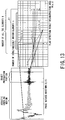
- Fig. 12 is an explanatory diagram of a case of the ultrasonic flaw detector 1 obtaining center coordinates Ec of simultaneously driven elements and the like.
- the focal point Fj is a focal point of an ultrasonic wave which has entered an assumed plane from the center coordinates Ec of the simultaneously driven elements at the incident angle ⁇ and refracted at the refraction angle ⁇ converging at a set depth.
- the surface shape coordinates where a straight line with the refraction angle ⁇ passing through the focal point Fj intersects with the surface shape function S is taken as Sj (incident point Sj).
- the inclination of the surface of the pipe 2 at the surface shape coordinates Sj (the relative angle between the ultrasonic probe 11 and the surface of the pipe 2) is taken as ⁇ j.
- the ultrasonic flaw detector 1 sets coordinates on the pipe surface (step S21). Specifically, the ultrasonic flaw detector 1 determines the element coordinates Ei of the ultrasonic probe 11, and determines a surface shape function S based on the measurement result or the design data of the surface shape of the pipe 2.
- the ultrasonic flaw detector 1 calculates the focal point Fj of the ultrasonic wave transmitted from the simultaneously driven elements with the center coordinates Ec, using the flaw detection conditions used in the linear scanning (normal linear scanning) that is conducted when the surface shape of the pipe 2 is assumed to be planar (step S22). More specifically, the ultrasonic flaw detector 1 transmits an ultrasonic wave from the center coordinates Ec at an incident angle ⁇ , causes the propagation inside the pipe 2 at a refraction angle ⁇ obtained when assuming that the ultrasonic wave entered the pipe 2 having a planar shape, and assumes that a point reached at a desired convergence depth of the ultrasonic wave as the focal point Fj.
- the ultrasonic flaw detector 1 calculates an incident point Sj that is according to the actual surface shape, using the refraction angle ⁇ and the focal point Fj (step S23). Specifically, the ultrasonic flaw detector 1 draws a straight line of the refraction angle ⁇ passing through the focal point Fj, and takes the point of intersection of the straight line and the surface shape function S as the incident point Sj. The ultrasonic flaw detector 1 further calculates an inclination ⁇ j at the incident point Sj (step S24). The calculation method of the inclination ⁇ j will be described later in detail.
- the ultrasonic flaw detector 1 calculates the actual incident angle ⁇ j (the incident angle taking the surface shape into consideration) by using Snell's law and by using the focal point Fj, the refraction angle ⁇ , the incident point Sj, and the inclination ⁇ j which have been calculated, and known sound speed values in the acoustic coupling medium 3 and the pipe 2 (step S25).
- the actual incident angle ⁇ j is a parameter in the ultrasonic flaw detecting method of the present embodiment.
- the ultrasonic flaw detector 1 calculates the actual center coordinates Ecj (the center coordinates of simultaneously driven elements taking the surface shape into consideration) using the incident point Sj and the incident angle ⁇ j (step S26). Specifically, the ultrasonic flaw detector 1 draws a straight line from the incident point Sj with an inclination of the angle ⁇ j, and assumes that the center coordinates Ec closest to the straight line as Ecj.
- the ultrasonic flaw detector 1 calculates by numerical calculation, for each of 'n' elements having the center coordinates Ecj as the center, the shortest distance between the element coordinates Ei and the focal point Fj through the surface shape function S.
- the ultrasonic flaw detector 1 obtains the propagation time of each ultrasonic wave from a known sound speed, and calculates the difference from the minimum value as the delay time of each element (step S27).
- the ultrasonic flaw detector 1 conducts the flaw detection using the calculated delay time and adds up the waveforms received by the elements while reflecting the delay time.
- the ultrasonic flaw detector 1 thereby obtains a phase matched waveform Uj(t) (step S28).
- the ultrasonic flaw detector 1 associates the phase matched waveform Uj(t) and position information regarding the pipe 2 using the center coordinates Ecj, the incident point Sj, the focal point Fj, the refraction angle ⁇ , the incident angle ⁇ j, and the sound speeds of the acoustic coupling medium 3 and the pipe 2 (flaw detection conditions) (step S29).
- the ultrasonic flaw detector 1 calculates the ultrasonic wave propagation time using the flaw detection conditions described above, and obtains the intensity of the phase matched waveform Um(t) corresponding to a flaw detection result reconstruction area M(x, z).
- the ultrasonic flaw detector 1 can obtain a flaw detection result which has been reconstructed by plotting the intensity of a waveform Um corresponding to the coordinates M.
- the ultrasonic flaw detector 1 scans the ultrasonic probe 11 and installs it at the next flaw detection position, repeats the coordinate setting step S21 to the associating step S29, and obtains a similar flaw detection result at the next flaw detection position.
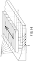
- Fig. 14 is an explanatory diagram of a case where the ultrasonic probe 11 performs scanning.
- the ultrasonic flaw detector 1 scans the ultrasonic probe 11 in a direction orthogonal to the direction of the lined up arrays.
- the ultrasonic flaw detector 1 can thereby obtain a three-dimensional flaw detection result.
- a similar result can be also obtained by conducting the scanning in a given direction in the case when other probes such as a matrix probe and a ring array probe are adopted.
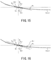
- the inclination ⁇ j is a relative angle between the ultrasonic probe 11 and the surface of the pipe 2.
- the inclination ⁇ j at the incident point Sj of an ultrasonic wave is calculated from surface shape coordinates Sj-1 and Sj+1 adjacent to the incident point Sj.
- the inclination ⁇ j can also be calculated using surface shape coordinates Sj-a and Sj+a that are apart from the incident point Sj by 'a'.
- the inclination ⁇ j can also be calculated by using each point from the surface shape coordinates Sj-a to Sj+a and performing linear approximation by a method such as a least squares method so as to pass through each point.
- Fig. 16 is another explanatory diagram of a case of obtaining the inclination ⁇ j of the surface of the pipe 2.
- the inclination ⁇ j may be calculated after removing data points that are highly deviated among a plurality of points from the surface shape coordinates Sj-a to Sj+a.
- the inclination ⁇ j at each position of the surface shape function S may be calculated first.
- the calculation is performed with respect to the center coordinates Ecj, the certain surface shape coordinates Sk, and the focal point Fj from coordinates S1 to coordinates Sn, according to Snell's law.
- a value with a minimum absolute value of the measurement result can be taken as the incident point Sj in the positional relationship of the center coordinates Ecj, the certain surface shape coordinates Sk, and the focal point Fj.
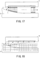
- Fig. 17 is an explanatory diagram of a method of measuring the surface shape function that uses a flight time method.
- Fig. 18 is an explanatory diagram of a method of measuring the surface shape function that uses aperture synthesis.
- the flight time method is a method of receiving an ultrasonic wave U transmitted from an ultrasonic element (element coordinates Ei) by the same ultrasonic element and reconstructing the shape of the surface of the pipe 2 from the propagation time of the received echo.
- a process of transmitting an ultrasonic wave U from an ultrasonic element (element coordinates Ei) and receiving the reflected wave by all the elements at element coordinates E1 to EN is performed.
- An element used for transmission is changed sequentially from the element coordinates E1 to EN, and the surface shape is measured using the measurement data.
- not all the pieces of the waveform data have to be used for the aperture synthesis process, and arbitrary data may be selected and be used for the process.
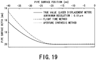
- Fig. 19 is a graph showing comparison between the surface shape functions obtained by the methods of Figs. 17 and 18 and a true value.
- the surface shape of the pipe 2 which is the true value was measured by a laser displacement meter. Measurement was performed with high accuracy by the aperture synthesis method, but it was found out that the error is great at the curvature portion according to the flight time method. This is because, with the flight time method, an echo is picked up whose propagation path is not the intended sound ray L but a shortest distance L'. Accordingly, the flight time method is not suitable for measurement of a complex surface shape.
- the flight time method is effective with an object with a small curvature or when grasping the relative position of the ultrasonic probe and the object, for example.
- Fig. 20 is a diagram showing a result of simulation performed under predetermined conditions for the intensity of an ultrasonic wave assuming that the surface shape is planar.
- Fig. 21 is a diagram showing a result of simulation performed under predetermined conditions for the intensity of an ultrasonic wave assuming that the surface shape is curved.
- the transmission delay conditions for the ultrasonic probe 11 are the refraction angle ⁇ of 45 degrees and the focal point forming position of 3/4t with respect to the thickness t of the pipe 2.
- Figs. 20 and 21 the intensity of an ultrasonic wave is shown based on sound field simulation for a case where the ultrasonic wave is emitted on the surface of the pipe 2 having a curved surface.
- the ultrasonic wave enters the pipe 2 from a part of a planar surface 2b of the surface of the pipe 2, it does not sufficiently enter from a curved surface 2a.
- the ultrasonic wave enters the pipe 2 also from the curved surface 2a.
- the ultrasonic flaw detector 1 can maintain the constant flaw detection conditions inside the pipe 2 by controlling, according to the surface shape of the pipe 2, the incident angle at each incident point such that the flaw detection conditions inside the pipe 2 are the same. Furthermore, the ultrasonic flaw detector 1 can emit the ultrasonic wave onto the curved surface 2a where flaw detection was not possible in Fig. 20 .
- Fig. 22 is a diagram showing a result of performing the reconstruction without taking the surface shape of the object into consideration.
- Fig. 23 is a diagram showing a result of performing the reconstruction, taking the surface shape of the object into consideration.
- the flaw detection is conducted under the condition that an ultrasonic wave is transmitted from a curved surface (an undulation) 33a on a flaw detection surface 33 of the object to a flaw 33b given to the object.
- the entire flaw 33b is the position where the influence of the curved surface 33a is exerted, but an indication of a corner echo 34 which is an echo from an opening of the flaw 33b occurring in a back surface 33c opposite the flaw detection surface 33 of the object is extended in an art shape. Furthermore, it can also be seen that a peak showing the corner echo 34 is positioned at an inner side than the surface of the back surface 33c. In addition, a tip echo 35 which is an echo from a tip of the flaw 33b on the inside of the object does not show a distinct peak. Furthermore, in Fig. 22 , there is a region showing an echo at a position where the flaw 33b does not exist (on the left side of the diagram).
- Fig. 23 the position of the corner echo 34 is clearer compared to Fig. 22 .
- the position of the peak is distinct for both the corner echo 34 and the tip echo 35, and the error in the position is greatly reduced.
- indications of the corner echo 34 and the tip echo 35 of the flaw 33b given to the inside of the object which receives the influence of the curved surface 33a are unclear, and also, the indication position of the flaw 33b includes an error with respect to the actual position of the flaw 33b.
- the ultrasonic flaw detector 1 of the present embodiment and the flaw detection method are capable of conducting accurate ultrasonic flaw detection by conducting flaw detection according to the surface shape of an object and reconstructing the flaw detection result according to the surface shape.
- the ultrasonic flaw detector 1 and the flaw detection method can thereby conduct the ultrasonic flaw detection with high detection accuracy on the surface of an object having a complex shape.
- a difference in sensitivity may occur depending on the surface shape of the object due to the angle of beam spread of the ultrasonic wave, the transmittance obtained based on the relation between the inclination ⁇ j and the incident angle ⁇ j, and the like. This means that the flaw detection accuracy varies depending on the influence of the surface shape of the object, and may lead to a significant measurement error.
- the ultrasonic flaw detector 1 and the flaw detection method of the present embodiment may perform calculation based on the surface shape of the object and the angle of beam spread of the ultrasonic wave and may maintain the intensity of the incident waves converging on the focal point to be constant.
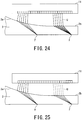
- Fig. 24 is an explanatory diagram representing a case where a difference in sensitivity arises due to a difference between surface shapes of the pipe 2.
- the intensity of an ultrasonic wave U entering the planar surface 2b of the pipe 2 is greater than that of an ultrasonic wave U entering the curved surface 2a, and the difference in the incident points on the curved surface 2a and the planar surface 2b results in the difference in the flaw detection accuracy.
- the gain of an ultrasonic wave oscillated from an ultrasonic element that is used is increased in advance for a surface shape with the lowest sensitivity, or by taking the surface shape with the lowest sensitivity in consideration, the gain of an ultrasonic wave entering a surface shape at which the sensitivity is not easily reduced is lowered in advance.
- Fig. 25 is an explanatory diagram of a case where the gain of the ultrasonic wave U is adjusted according to the surface shape of the pipe 2.
- the ultrasonic flaw detector 1 lowers, in advance, the gain of an ultrasonic wave U having an incident point being on the planar surface 2b with a high sensitivity.
- the intensity of the ultrasonic wave U inside the pipe 2 thereby becomes almost equal for the curved surface 2a and the planar surface 2b.
- the number of ultrasonic elements that are simultaneously driven is increased more than a normal case with respect to a surface shape with a lower sensitivity.
- Fig. 26 is an explanatory diagram of a case where the number of simultaneously driven elements is adjusted according to the surface shape of the pipe 2.
- the ultrasonic flaw detector 1 has increased the number 'n1' of the ultrasonic elements that oscillate the ultrasonic waves that are emitted on the curved surface 2a than the number 'n2' of the ultrasonic elements that oscillate the ultrasonic waves whose incident points are on the planar surface 2b.
- the intensity of the ultrasonic wave U inside the pipe 2 thereby becomes almost equal for the curved surface 2a and the planar surface 2b.
- the method of estimating the ultrasonic intensity at a focal point F may include a general ray tracing method, or other numerical analysis methods such as a difference method, a finite-element method, an FDTD method and a CIP method.
- the ultrasonic flaw detector 1 and the flaw detection method may be adopted with other flaw detecting methods such as sector scan, which scans the refraction angle fanwise, and Dynamic Depth Focusing (DDF), which changes the focal point depth according to an area to be measured.
- sector scan which scans the refraction angle fanwise
- DDF Dynamic Depth Focusing
- Fig. 27 is an explanatory diagram of a case where the sector scan is applied to ultrasonic flaw detection without taking the surface shape of the pipe 2 into consideration.
- Fig. 28 is an explanatory diagram of a case where the sector scan is applied to ultrasonic flaw detection, taking the surface shape of the pipe 2 into consideration.
- ultrasonic waves In the case the surface shape of the pipe 2 is planar, ultrasonic waves ideally enter the pipe 2 like the ultrasonic waves U1 shown by dotted lines in Fig. 27 . However, if the surface shape of the pipe 2 is curved, ultrasonic waves do not enter from intended positions, and the ultrasonic waves enter the pipe 2 like the ultrasonic waves U2 shown by solid lines in Fig. 27 . As a result, the flaw detection range will not take an ideal fan shape, and hence, the flaw detection cannot be conducted accurately.
- the ultrasonic flaw detector of the present embodiment and its method take the surface shape of the pipe 2 into consideration, and perform the back calculation of the simultaneously driven elements from the flaw detection range having an ideal fan shape of the ultrasonic waves U1 shown in Fig. 27 . It therefore becomes possible, as shown in Fig. 28 , to conduct the ideal flaw detection even if the surface shape is curved, as in a case where the surface shape is planar.
- analysis unit 15 and the calculation unit 18 can be realized, in each embodiment, by a processing unit, a memory, a program for causing these to operation, and the like. Accordingly, although the analysis unit 15 and the calculation unit 18 have been described as separate structural elements, they can also be integrated into one piece of hardware.
Description
- The present invention relates to an ultrasonic flaw detector and an ultrasonic flaw detecting method.
- Ultrasonic flaw detection testing is a non-destructive technology that enables checking of the soundness of the surface and the inside of a construction material, and is a testing technology indispensable in various fields. Especially, in recent years, there is a demand for testing of a construction having a complex surface shape such as a curved surface, and the technological demand regarding ultrasonic flaw detection is becoming higher.
- In the case an object to be inspected has a complex surface shape, there is a problem that an ultrasonic wave cannot be appropriately emitted on the object. For example, at a weld line and its heat-affected zone, a portion which is designed to be planar unintentionally becomes non-planar due to a strain or chevron-like deformation caused by welding heat input or a convex shape formed after molten metal is poured.
- Furthermore, various piping structures typified by a nozzle stub of, for example, a nuclear power plant or a thermal power plant, or a platform region of a turbine blade is designed to have a complex shape, and even if constructed as designed, testing thereof is difficult. If such object is taken as the object of the ultrasonic flaw detection testing, an ultrasonic wave cannot be emitted on the object or, even if the ultrasonic wave is emitted, a desired refraction angle may not be obtained.
- In contrast, a phased array (PA) is a technology of forming a given waveform by arranging small ultrasonic sensors, and varying the timing (delay time) of the sensors and emitting ultrasonic waves. Compared to a monolithic probe that can only emit ultrasonic waves at a predetermined angle, the phased array can possibly cope with a complex shape.
- However, with the phased array technology, the delay time reflecting the shape has to be calculated for each target. Further, the value of the shape to be reflected should include not only the values on a drawing, but also the as-built values (a drawing created based on existing conditions and analysis data). Accordingly, to carry out ultrasonic flaw detection on a complex-shaped region, a technology for measuring the surface shape of a target with high accuracy is needed, as well as a technology for controlling ultrasonic waves (calculating the delay time) according to the curvature.
- To solve the above matters, there is conventionally proposed a method which measures the surface shape of an object by an ultrasonic probe, optimizes the transmission delay time of the PA according to the measured shape, and conducts testing (for example, Japanese Patent Laid-Open No.
2007-170877 - However, the
Patent Document 1 only describes optimization of delay time conditions according to the surface shape of an object. Therefore, when using an electronic scan, which, typified by a linear scan, sequentially moves elements to be used, elements to be used are fixed with respect to a focal point, and thus, there arises a problem that an ultrasonic wave enters from an unintended incident point. There is also provided a problem of an ultrasonic wave not reaching a test portion due to use of an element at a blind angle. - On the other hand, emitting an ultrasonic wave according to the surface shape allows to cope with the problem of the incident angle of the ultrasonic wave changing. However, at the time of displaying a flaw detection result, a flaw indication echo is displayed at a portion different from the actual detection position in a flaw detection result that is displayed in a case if analysis has been performed without taking the influence of the surface shape into consideration.
- The position of an indication echo cannot be accurately identified unless the flaw detection result is separately corrected in consideration of the influence of the surface shape, and an error occurs in the detection position. That is, the flaw detection accuracy is greatly reduced. It is also conceivable that an indication echo is extended and is displayed with a shape different from the actual flaw. This can be overcome if an inspector corrects the detection position error by hand calculation while taking the influence of the surface shape into consideration. But this will increase the burden on the inspector. In addition, if the surface shape is complex, correction will require much skill.
- Furthermore, an adaptive system for non-destructive examination is disclosed in "An adaptive system for advanced NDT applications using phased arrays", by S. Mahaut et al., Ultrasonics 36 (1998) 127 - 131, XP 004119500. Therein, delay and amplitude laws are supplied to form an ultrasonic beam.
- In addition, an ultrasonic flaw detecting method is disclosed in
JP 2006 047328 A - The present invention has been made in view of the above circumstances, and an object thereof is to provide an ultrasonic flaw detector and a method thereof, which are capable of achieving high detecting accuracy regardless of the surface shape of an object.
- An embodiment of the ultrasonic flaw detector of the present invention provided for solving the problems described above is defined in
claim 1. - Furthermore, an embodiment of the ultrasonic flaw detecting method of the present invention provided for solving the problems described above is defined in claim 7.
- With the ultrasonic flaw detection and the method thereof according to the embodiments of the present invention can achieve high detection accuracy regardless of the surface shape of an object to be inspected.
-
-
Fig. 1 is a functional block diagram showing a configuration of an embodiment of an ultrasonic flaw detector according to the present invention; -
Fig. 2 is an explanatory diagram showing an example of general flaw detection; -
Fig. 3 is an explanatory diagram showing an example of general reconstruction of a flaw detection result; -
Fig. 4 is a flow chart showing a general flaw detecting method; -
Fig. 5 is an explanatory diagram of flaw detection testing where a curved surface is formed on the surface of a pipe; -
Fig. 6 is an explanatory diagram of an ultrasonic wave propagation path where flaw detection is conducted without taking the surface shape of a pipe into consideration; -
Fig. 7 is an explanatory diagram of an ultrasonic wave propagation path where flaw detection is conducted, taking the surface shape of a pipe into consideration; -
Fig. 8 is an explanatory diagram showing an ultrasonic wave propagation path where flaw detection is conducted by an ultrasonic flaw detector according to the present embodiment; -
Fig. 9 is a flow chart describing a concept of a flaw detecting method of the ultrasonic flaw detector of the present embodiment; -
Fig. 10 is a flow chart describing a flaw detection condition setting process conducted by the ultrasonic flaw detector of the present embodiment; -
Fig. 11 is an explanatory diagram showing a state of propagation of an ultrasonic wave in a pipe; -
Fig. 12 is an explanatory diagram of a case of the ultrasonic flaw detector obtaining center coordinates Ec of simultaneously driven elements and the like; -
Fig. 13 is an explanatory diagram showing an example of a phase matched waveform Uj(t) obtained by the ultrasonic flaw detector according to the present embodiment; -
Fig. 14 is an explanatory diagram of a case where an ultrasonic probe performs scanning; -
Fig. 15 is an explanatory diagram of a case of obtaining an inclination θj of a pipe surface; -
Fig. 16 is another explanatory diagram of a case of obtaining an inclination θj of a pipe surface; -
Fig. 17 is an explanatory diagram of a method of measuring a surface shape function that uses a flight time method; -
Fig. 18 is an explanatory diagram of a method of measuring a surface shape function that uses aperture synthesis; -
Fig. 19 is a graph showing comparison between the surface shape functions obtained by the methods ofFigs. 17 and 18 and a true value; -
Fig. 20 is a diagram showing a result of simulation performed under predetermined conditions for the intensity of an ultrasonic wave assuming that the surface shape is planar; -
Fig. 21 is a diagram showing a result of simulation performed under predetermined conditions for the intensity of an ultrasonic wave assuming that the surface shape is curved; -
Fig. 22 is a diagram showing a result of performing reconstruction without taking the surface shape of an object into consideration; -
Fig. 23 is a diagram showing a result of performing reconstruction, taking the surface shape of an object into consideration; -
Fig. 24 is an explanatory diagram of a case where a difference in sensitivity arises due to a difference between surface shapes of a pipe; -
Fig. 25 is an explanatory diagram of a case where a gain of an ultrasonic wave U is adjusted according to the surface shape of a pipe; -
Fig. 26 is an explanatory diagram of a case where the number of simultaneously driven elements is adjusted according to the surface shape of a pipe; -
Fig. 27 is an explanatory diagram of a case where a sector scan is applied to ultrasonic flaw detection without taking the surface shape of a pipe into consideration; and -
Fig. 28 is an explanatory diagram of a case where a sector scan is applied to ultrasonic flaw detection, taking the surface shape of a pipe into consideration. - An embodiment of an ultrasonic flaw detector according to the present invention and a method thereof will be described hereunder with reference to the accompanying drawings.
-
Fig. 1 is a functional block diagram illustrating a configuration of an embodiment of the ultrasonic flaw detector according to the present invention. According to the present embodiment, an object to be detected is apipe 2, and an example will be described with reference to a case in which flaw detection using ultrasonic waves is conducted to a flaw portion of thepipe 2. The dotted line inFig. 1 indicates the center of the pipe. - The ultrasonic flaw detector of the present example is basically provided with an ultrasonic probe, and, in association with the ultrasonic probe, an ultrasonic transmitter/receiver and a drive element control unit for controlling a drive element, and a calculation unit for calculating control information of the drive element.
- More specifically, an
ultrasonic flaw detector 1 is generally composed of anultrasonic probe 11, and, in association with the ultrasonic probe, an ultrasonic transmitter/receiver 12 for transmitting/receiving ultrasonic waves and a drive element control unit 13 for controlling a drive element, and acalculation unit 18 for calculating information for the drive element control unit 13 to control a drive element. Furthermore, as described later, theultrasonic flaw detector 1 connected to the drive element control unit 13 is provided with asignal recording unit 14, ananalysis unit 15, adisplay unit 16, and adesign database 17. - The
ultrasonic probe 11 is a well-known ultrasonic probe that transmits/receives ultrasonic waves U. Theultrasonic probe 11 emits an ultrasonic wave U on thepipe 2 viaacoustic coupling medium 3 by driving a plurality of ultrasonic elements, and receives a reflected ultrasonic wave from thepipe 2. Theacoustic coupling medium 3 is a medium that is capable of propagating an ultrasonic wave, such as water, glycerin, machine oil, acrylic gel, or polystyrene gel, for example. Further, in the present embodiment, illustration of theacoustic coupling medium 3 may be sometimes omitted. - The
ultrasonic probe 11 has ultrasonic elements that are one-dimensionally arranged and is generally referred to as a linear array sensor. - The
ultrasonic probe 11 includes, for example, a mechanism for generating an ultrasonic wave, a damping material for damping an ultrasonic wave, and a front plate attached to a plane of oscillation of an ultrasonic wave. The mechanism for generating an ultrasonic wave is, for example, ceramics or ceramic composite materials, or a piezoelectric element that generates an ultrasonic wave by piezoelectric effect, or a piezoelectric element formed of a polymer film. - Furthermore, the ultrasonic probe may be a 1.5-dimensional array sensor in which elements are unequally divided in the depth direction of a linear array sensor, a matrix array sensor in which elements are two-dimensionally arranged, or a ring array sensor in which ring-shaped elements are concentrically arranged. The ultrasonic probe may also be a divided ring array sensor in which the elements of a ring array sensor are divided in the circumferential direction, a random array sensor in which elements are randomly arranged, an arc array sensor in which elements are arranged at positions in the circumferential direction of an arc, a spherical array sensor in which elements are arranged on the surface of a sphere, or any other array sensor.
- Hereunder, the function of each of the structural elements described above will be explained. The ultrasonic transmitter/receiver 12 is connected to the
ultrasonic probe 11, and handles transmission/reception of an ultrasonic wave. The drive element control unit 13 controls an ultrasonic element that is to be actually driven at the ultrasonic transmitter/receiver 12 in response to drive control information for an ultrasonic element calculated by thecalculation unit 18. The drive element control unit 13 includes a transmission/receptionsensitivity adjustment unit 21, and adelay control unit 22, in which the transmission/receptionsensitivity adjustment unit 21 adjusts transmission/reception sensitivity for an ultrasonic wave from the ultrasonic transmitter/receiver 12. On the other hand, thedelay control unit 22 controls the oscillation of each of a plurality of ultrasonic elements according to a given time. - Furthermore, the
signal recording unit 14 stores a received signal (ultrasonic signal) received by the drive element control unit 13. - The
analysis unit 15 analyzes the received signal stored in thesignal recording unit 14 and calculates a flaw detection result. Specifically, theanalysis unit 15 calculates the flaw detection result based on the propagation path of an ultrasonic wave obtained on the basis of the surface information of thepipe 2 on which the ultrasonic wave is emitted. That is, theanalysis unit 15 obtains the propagation path of the ultrasonic wave using a relative angle between the surface, of thepipe 2, at a position in which the ultrasonic wave is emitted and theultrasonic probe 11. - The
display unit 16 displays the flaw detection result obtained by theanalysis unit 15. Thedesign database 17 that is connected to theanalysis unit 15 stores in advance data on the surface shape of thepipe 2 at the stage of design. - Furthermore, the
ultrasonic flaw detector 1 is not limited to the configuration mentioned above as long as it adds delay time to the ultrasonic probe composed of a plurality of piezoelectric elements and controls the transmission/reception of ultrasonic waves. Moreover, a flaw detecting method of performing transmission/reception delay control of ultrasonic waves using a plurality of piezoelectric elements such as a phased array is well known, and hence, a detailed explanation thereof is omitted. - When installing the
ultrasonic probe 11, a wedge may be used to use an angle with a high degree of directivity. The wedge is an isotropic material that allows propagation of an ultrasonic wave and where acoustic impedance is grasped. The wedge is formed from acrylic, polyimide, gel or any other polymer materials, for example. Further, in order to prevent the influence of a multiply reflected wave within the wedge on a flaw detection result, damping materials may be arranged within and outside the wedge, a mountain-shaped wave-absorbing form may be provided, or a mechanism for multiple reflection reduction may be provided. - Next, a flaw detecting method that uses a basic phased array (PA) will be described.
-
Fig. 2 is an explanatory diagram showing an example of basic flaw detection, andFig. 3 is an explanatory diagram showing an example of basic reconstruction of a flaw detection result. - With reference to
Figs. 2 and 3 , to emit ultrasonic waves U into thepipe 2 at a given refraction angle β and focal positions, a plurality of ultrasonic elements (piezoelectric elements) provided to theultrasonic probe 11 of the PA are given with appropriate delay time and are then oscillated. The direction and focal positions of the ultrasonic waves are thereby controlled. - If there is a reflector such as a flaw inside the
pipe 2, an ultrasonic wave U emitted into thepipe 2 is reflected and dispersed. The reflected ultrasonic wave is received by an ultrasonic element of theultrasonic probe 11. The waveform of the received ultrasonic wave is imaged in the direction of the electronic scan according to an incident angle α and the refraction angle β of the ultrasonic wave which have been set. - This imaging is generally referred to as B-scan or S-scan. As shown in
Fig. 3 , an image is reconstructed based on the incident angle α and the refraction angle β that are according to the flaw detection conditions at the time of flaw detection. In the following explanation, the B-scan will be is used. - Herein, a basic flaw detecting method will be described using the flow chart of
Fig. 4 . - First, delay time is calculated according to flaw detection conditions such as the refraction angle β and the focal position on the pipe 2 (step S1). Then, the
ultrasonic probe 11 is installed above thepipe 2, and scanning is started (step S2). - Flaw detection is conducted on the
pipe 2 according to the scanning (step S3), and data on the waveform of the ultrasonic wave obtained according to the flaw detection conditions such as the refraction angle β is reconstructed, and a B-scan is prepared (step S4). Thereafter, the scanning position of thepipe 2 is changed, and steps from the installation/operation step S2 to the reconstruction step S4 are repeated. - Here, if the flaw detection step S3 and the reconstruction step S4 are performed under flaw detection conditions assuming a planarity condition in a case where there is a curved surface such as an undulation (a partial curve) due to excessive weld metal or grinding (
Fig. 5 ) or in a case thepipe 2 is not planar from the start, an ultrasonic wave does not enter at an intended angle. In addition, an error occurs in the detection result. -
Fig. 5 is an explanatory diagram of the flaw detection testing in which acurved surface 2a is formed on the surface of thepipe 2. - In the case where the calculation is performed under the flaw detection conditions assuming a planarity condition as shown in
Fig. 2 , the flaw detection is conducted with the incident angle α from any position of theultrasonic probe 11. Therefore, if an ultrasonic wave is emitted on the surface of thepipe 2 having acurved surface 2a such as an undulation, the refraction angle β is not fixed due to Snell's law, and the propagation path of an ultrasonic wave varies depending on the incident position. - The above process prevents not only the flaw detection with an intended ultrasonic wave, but also, depending on the incident angle α, the emission of an ultrasonic wave on the
pipe 2. Further, in the case of evaluating a received ultrasonic signal, if reconstruction is conducted under the planarity condition without taking the surface shape of thepipe 2 into consideration, deviation from the actual propagation path of an ultrasonic wave will occur. - This point will be described in greater detail hereunder.
-
Fig. 6 is an explanatory diagram of an ultrasonic wave propagation path where the flaw detection is conducted without taking the surface shape of thepipe 2 into consideration.Fig. 7 is an explanatory diagram of an ultrasonic wave propagation path where the flaw detection is conducted, taking the surface shape of thepipe 2 into consideration. - As shown in
Fig. 6 , ultrasonic waves U are transmitted under a condition assuming that the surface of thepipe 2 is a planar surface. In this case, the incident angles α are uniform, but the refraction angles β become non-uniform under the influence of the surface shape and the incident ultrasonic waves will follow paths different from the intended path. A flaw position obtained by the reconstruction will include an error with respect to the actual position of a flaw existing on thepipe 2, which will result in an error or overlooking in the evaluation of a flaw detection result. - In
Fig. 7 , the surface shape of thepipe 2 is taken into consideration, and the delay time is controlled such that an ultrasonic wave enters a focal point F of thepipe 2. With a general linear scan, the combination of ultrasonic elements that are simultaneously used (simultaneously driven elements) is decided in advance. These simultaneously driven elements move sequentially. The constants in the conditions for the flaw detection are the center position Ec of the simultaneously driven elements which are the starting points of the ultrasonic waves and the focal points F within thepipe 2 which are the goal points, and the parameters are incident points S. - That is, also in this case, the refraction angles β are not necessarily uniform, and a general requirement for ultrasonic testing adopted by standards (such as JIS) that "flaw detection testing is conducted with uniform refraction angles β" is not satisfied. Furthermore, depending on the surface shape of the
pipe 2, an element that may not properly emit an ultrasonic wave is possibly unavoidably used, and an ultrasonic wave of sufficient intensity may not be emitted. - In contrast to the ultrasonic flaw detection technology as described above, the
ultrasonic flaw detector 1 of the present embodiment, in consideration of the surface shape of thepipe 2, can suitably emit ultrasonic waves on thepipe 2 and also make the refraction angles β uniform. - An ultrasonic wave propagation path in a case of conducting flaw detection by the
ultrasonic flaw detector 1 of the present embodiment will be described with reference toFig. 8 . - With reference to
Fig. 8 , theultrasonic flaw detector 1 conducts the flaw detection by calculating control information regarding an ultrasonic element by thecalculation unit 18, and driving the ultrasonic element by the drive element control unit 13 based on the control information. Specifically, the incident points S and the focal points F are made constants based on the known surface shape of thepipe 2 and desired refraction angles β, and optimal ultrasonic elements are back calculated with the center position Ec of the simultaneously driven elements as a parameter. Theultrasonic flaw detector 1 uses the obtained ultrasonic elements and the performs the flaw detection by controlling the delay time of the ultrasonic elements. Theultrasonic flaw detector 1 can thereby always maintain uniform refraction angles β. - Herein now, a flaw detecting method of the
ultrasonic flaw detector 1 of the present embodiment will be described. -
Fig. 9 is a flow chart describing an overview of a flaw detecting method of theultrasonic flaw detector 1 of the present embodiment. - First, the
ultrasonic probe 11 is installed above thepipe 2 and scanning is started (step S11), and the surface shape of thepipe 2 is measured using a shape measuring device (step S12). The surface shape may be obtained by measuring the as-built shape, or by importing the measurement data stored in thedesign database 17. The details of the shape acquisition step S12 will be described later. - Next, in step S13, the
delay control unit 22 calculates the optimal delay time for an ultrasonic element with respect to the surface shape, theultrasonic probe 11 conducts the flaw detection on the pipe 2 (step S14), the ultrasonic data according to the surface shape is reconstructed, and a B-scan is generated (step S15). - Further, for generation of a flaw detection result reconstruction area M, there are conceivable a method of calculating the position on a flaw detection result M from an ultrasonic signal Uj, and a method of calculating the position of an ultrasonic signal Uj corresponding to the coordinates from the coordinate points on the flaw detection result M.
- Thereafter, the installation step S11 to the reconstruction step S15 are repeated until the flaw detection is completed.
- Hereunder, a process for obtaining center coordinates (the center position Ec in
Fig. 8 ) of simultaneously driven elements used for flaw detection will be described. -
Fig. 10 is a flow chart describing a flaw detection condition setting process conducted by theultrasonic flaw detector 1 of the present embodiment.Fig. 11 is an explanatory diagram showing a state of propagation of an ultrasonic wave in thepipe 2.Fig. 12 is an explanatory diagram of a case of theultrasonic flaw detector 1 obtaining center coordinates Ec of simultaneously driven elements and the like. - In the present embodiment, an explanation will be given taking a linear array probe as a representative example, and thus, coordinate information will be expressed in two dimensions (x, z). If a probe with two-dimensionally arranged piezoelectric elements, such as a matrix array, is used, it will be set in three dimensions (x, y, z).
- When the coordinates of each element are Ei(x, z) (i = 1, 2, ..., N), and the number of simultaneously driven elements is n (1 ≤ n ≤ N), elements from the element coordinates Ei to element coordinates Ei + n will be used for flaw detection. The element center coordinates of all the simultaneously driven elements is Ec(x, z). Here, the coordinates of the surface shape of the
pipe 2 are given by a surface shape function S(x, z). A sequence j (pattern) of the flaw detection is performed up to 'm' times on the surface shape function S, and a focal point where ultrasonic waves converge is taken as Fj(x, z). - The focal point Fj is a focal point of an ultrasonic wave which has entered an assumed plane from the center coordinates Ec of the simultaneously driven elements at the incident angle α and refracted at the refraction angle β converging at a set depth. The surface shape coordinates where a straight line with the refraction angle β passing through the focal point Fj intersects with the surface shape function S is taken as Sj (incident point Sj). The inclination of the surface of the
pipe 2 at the surface shape coordinates Sj (the relative angle between theultrasonic probe 11 and the surface of the pipe 2) is taken as θj. - Next, a flaw detection condition setting process conducted by the
ultrasonic flaw detector 1 of the present embodiment will be described with reference to the flow chart ofFig. 10 . - In the flaw detection condition setting process, first, the
ultrasonic flaw detector 1 sets coordinates on the pipe surface (step S21). Specifically, theultrasonic flaw detector 1 determines the element coordinates Ei of theultrasonic probe 11, and determines a surface shape function S based on the measurement result or the design data of the surface shape of thepipe 2. - Then, the
ultrasonic flaw detector 1 calculates the focal point Fj of the ultrasonic wave transmitted from the simultaneously driven elements with the center coordinates Ec, using the flaw detection conditions used in the linear scanning (normal linear scanning) that is conducted when the surface shape of thepipe 2 is assumed to be planar (step S22). More specifically, theultrasonic flaw detector 1 transmits an ultrasonic wave from the center coordinates Ec at an incident angle α, causes the propagation inside thepipe 2 at a refraction angle β obtained when assuming that the ultrasonic wave entered thepipe 2 having a planar shape, and assumes that a point reached at a desired convergence depth of the ultrasonic wave as the focal point Fj. - Furthermore, the
ultrasonic flaw detector 1 calculates an incident point Sj that is according to the actual surface shape, using the refraction angle β and the focal point Fj (step S23). Specifically, theultrasonic flaw detector 1 draws a straight line of the refraction angle β passing through the focal point Fj, and takes the point of intersection of the straight line and the surface shape function S as the incident point Sj. Theultrasonic flaw detector 1 further calculates an inclination θj at the incident point Sj (step S24). The calculation method of the inclination θj will be described later in detail. - The
ultrasonic flaw detector 1 calculates the actual incident angle αj (the incident angle taking the surface shape into consideration) by using Snell's law and by using the focal point Fj, the refraction angle β, the incident point Sj, and the inclination θj which have been calculated, and known sound speed values in theacoustic coupling medium 3 and the pipe 2 (step S25). The actual incident angle αj is a parameter in the ultrasonic flaw detecting method of the present embodiment. - The
ultrasonic flaw detector 1 calculates the actual center coordinates Ecj (the center coordinates of simultaneously driven elements taking the surface shape into consideration) using the incident point Sj and the incident angle αj (step S26). Specifically, theultrasonic flaw detector 1 draws a straight line from the incident point Sj with an inclination of the angle αj, and assumes that the center coordinates Ec closest to the straight line as Ecj. - Then, the
ultrasonic flaw detector 1 calculates by numerical calculation, for each of 'n' elements having the center coordinates Ecj as the center, the shortest distance between the element coordinates Ei and the focal point Fj through the surface shape function S. Theultrasonic flaw detector 1 obtains the propagation time of each ultrasonic wave from a known sound speed, and calculates the difference from the minimum value as the delay time of each element (step S27). - Next, the
ultrasonic flaw detector 1 conducts the flaw detection using the calculated delay time and adds up the waveforms received by the elements while reflecting the delay time. Theultrasonic flaw detector 1 thereby obtains a phase matched waveform Uj(t) (step S28). - An explanation will be given with reference to an explanatory diagram of
Fig. 13 showing an example of the phase matched waveform Uj(t) obtained by theultrasonic flaw detector 1 according to the present embodiment. Theultrasonic flaw detector 1 associates the phase matched waveform Uj(t) and position information regarding thepipe 2 using the center coordinates Ecj, the incident point Sj, the focal point Fj, the refraction angle β, the incident angle αj, and the sound speeds of theacoustic coupling medium 3 and the pipe 2 (flaw detection conditions) (step S29). - Specifically, the
ultrasonic flaw detector 1 calculates the ultrasonic wave propagation time using the flaw detection conditions described above, and obtains the intensity of the phase matched waveform Um(t) corresponding to a flaw detection result reconstruction area M(x, z). Theultrasonic flaw detector 1 can obtain a flaw detection result which has been reconstructed by plotting the intensity of a waveform Um corresponding to the coordinates M. - The
ultrasonic flaw detector 1 scans theultrasonic probe 11 and installs it at the next flaw detection position, repeats the coordinate setting step S21 to the associating step S29, and obtains a similar flaw detection result at the next flaw detection position. -
Fig. 14 is an explanatory diagram of a case where theultrasonic probe 11 performs scanning. - When a linear array is adopted as the
ultrasonic probe 11, theultrasonic flaw detector 1 scans theultrasonic probe 11 in a direction orthogonal to the direction of the lined up arrays. Theultrasonic flaw detector 1 can thereby obtain a three-dimensional flaw detection result. A similar result can be also obtained by conducting the scanning in a given direction in the case when other probes such as a matrix probe and a ring array probe are adopted. - Herein, a method of obtaining the inclination θj of the surface of the
pipe 2 at the surface shape coordinates Sj will be described, in which the inclination θj is a relative angle between theultrasonic probe 11 and the surface of thepipe 2. - Referring to
Fig. 15 , an explanation will be given for a case of obtaining the inclination θj of the surface of thepipe 2. - The inclination θj at the incident point Sj of an ultrasonic wave is calculated from surface shape coordinates Sj-1 and Sj+1 adjacent to the incident point Sj. The inclination θj can also be calculated using surface shape coordinates Sj-a and Sj+a that are apart from the incident point Sj by 'a'. The inclination θj can also be calculated by using each point from the surface shape coordinates Sj-a to Sj+a and performing linear approximation by a method such as a least squares method so as to pass through each point.
-
Fig. 16 is another explanatory diagram of a case of obtaining the inclination θj of the surface of thepipe 2. - Since noise sometimes occurs in the shape measurement result, if all the pieces of data are used, θj' with an error with respect to the actual inclination θj may be calculated. For this reason, the inclination θj may be calculated after removing data points that are highly deviated among a plurality of points from the surface shape coordinates Sj-a to Sj+a.
- Furthermore, when identifying the incident point Sj from the center coordinates Ecj, certain surface shape coordinates Sk, and the focal point Fj, the inclination θj at each position of the surface shape function S may be calculated first. In this case, the calculation is performed with respect to the center coordinates Ecj, the certain surface shape coordinates Sk, and the focal point Fj from coordinates S1 to coordinates Sn, according to Snell's law. A value with a minimum absolute value of the measurement result can be taken as the incident point Sj in the positional relationship of the center coordinates Ecj, the certain surface shape coordinates Sk, and the focal point Fj.
- Next, an explanation will be given on the method of measuring the surface shape function S of the
pipe 2 with reference toFigs. 17 and 18. Fig. 17 is an explanatory diagram of a method of measuring the surface shape function that uses a flight time method.Fig. 18 is an explanatory diagram of a method of measuring the surface shape function that uses aperture synthesis. - The flight time method is a method of receiving an ultrasonic wave U transmitted from an ultrasonic element (element coordinates Ei) by the same ultrasonic element and reconstructing the shape of the surface of the
pipe 2 from the propagation time of the received echo. - On the other hand, with the aperture synthesis method, a process of transmitting an ultrasonic wave U from an ultrasonic element (element coordinates Ei) and receiving the reflected wave by all the elements at element coordinates E1 to EN is performed. An element used for transmission is changed sequentially from the element coordinates E1 to EN, and the surface shape is measured using the measurement data. At this time, not all the pieces of the waveform data have to be used for the aperture synthesis process, and arbitrary data may be selected and be used for the process.
-
Fig. 19 is a graph showing comparison between the surface shape functions obtained by the methods ofFigs. 17 and 18 and a true value. - The surface shape of the
pipe 2 which is the true value was measured by a laser displacement meter. Measurement was performed with high accuracy by the aperture synthesis method, but it was found out that the error is great at the curvature portion according to the flight time method. This is because, with the flight time method, an echo is picked up whose propagation path is not the intended sound ray L but a shortest distance L'. Accordingly, the flight time method is not suitable for measurement of a complex surface shape. - However, since, compared to the aperture synthesis method, the amount of data and the signal processing time can be greatly reduced, the flight time method is effective with an object with a small curvature or when grasping the relative position of the ultrasonic probe and the object, for example.
- For measurement of the surface shape function, other methods of measuring the surface shape by using the
ultrasonic probe 11 can also be adopted, such as a method of adopting a delay time according to which the focal point is on the surface of the object and measuring the shape of the surface from the delay time, and a method of plotting concentrically the echoes obtained by the flight time method for each element and connecting the tangents. - An explanation will be given on a result of simulating the ultrasonic wave propagation path in a case where the
ultrasonic flaw detector 1 of the present embodiment is used. -
Fig. 20 is a diagram showing a result of simulation performed under predetermined conditions for the intensity of an ultrasonic wave assuming that the surface shape is planar.Fig. 21 is a diagram showing a result of simulation performed under predetermined conditions for the intensity of an ultrasonic wave assuming that the surface shape is curved. - The transmission delay conditions for the
ultrasonic probe 11 are the refraction angle β of 45 degrees and the focal point forming position of 3/4t with respect to the thickness t of thepipe 2. InFigs. 20 and 21 , the intensity of an ultrasonic wave is shown based on sound field simulation for a case where the ultrasonic wave is emitted on the surface of thepipe 2 having a curved surface. - As shown in
Fig. 20 , although the ultrasonic wave enters thepipe 2 from a part of aplanar surface 2b of the surface of thepipe 2, it does not sufficiently enter from acurved surface 2a. On the other hand, as shown inFig. 21 , in the case of emitting the ultrasonic wave under the transmission delay conditions according to thecurved surface 2a, the ultrasonic wave enters thepipe 2 also from thecurved surface 2a. - The
ultrasonic flaw detector 1 can maintain the constant flaw detection conditions inside thepipe 2 by controlling, according to the surface shape of thepipe 2, the incident angle at each incident point such that the flaw detection conditions inside thepipe 2 are the same. Furthermore, theultrasonic flaw detector 1 can emit the ultrasonic wave onto thecurved surface 2a where flaw detection was not possible inFig. 20 . - Hereunder, there is described a result of taking a test object that simulates an undulation of a weld portion and has a flaw as an object, and conducting the flaw detection by the
ultrasonic flaw detector 1 of the present embodiment, and reconstructing the obtained ultrasonic signal. -
Fig. 22 is a diagram showing a result of performing the reconstruction without taking the surface shape of the object into consideration.Fig. 23 is a diagram showing a result of performing the reconstruction, taking the surface shape of the object into consideration. - In these examples, the flaw detection is conducted under the condition that an ultrasonic wave is transmitted from a curved surface (an undulation) 33a on a
flaw detection surface 33 of the object to aflaw 33b given to the object. - As shown in
Fig. 22 , theentire flaw 33b is the position where the influence of thecurved surface 33a is exerted, but an indication of acorner echo 34 which is an echo from an opening of theflaw 33b occurring in aback surface 33c opposite theflaw detection surface 33 of the object is extended in an art shape. Furthermore, it can also be seen that a peak showing thecorner echo 34 is positioned at an inner side than the surface of theback surface 33c. In addition, atip echo 35 which is an echo from a tip of theflaw 33b on the inside of the object does not show a distinct peak. Furthermore, inFig. 22 , there is a region showing an echo at a position where theflaw 33b does not exist (on the left side of the diagram). - On the other hand, in
Fig. 23 , the position of thecorner echo 34 is clearer compared toFig. 22 . In addition, the position of the peak is distinct for both thecorner echo 34 and thetip echo 35, and the error in the position is greatly reduced. - As described, with reconstruction that does not take the surface shape into consideration, indications of the
corner echo 34 and thetip echo 35 of theflaw 33b given to the inside of the object which receives the influence of thecurved surface 33a are unclear, and also, the indication position of theflaw 33b includes an error with respect to the actual position of theflaw 33b. - In contrast, with reconstruction that takes the surface shape into consideration, the indications of the
corner echo 34 and thetip echo 35 of theflaw 33b are shown clearly, and also, the indication position of theflaw 33b is accurate. - As described, the
ultrasonic flaw detector 1 of the present embodiment and the flaw detection method are capable of conducting accurate ultrasonic flaw detection by conducting flaw detection according to the surface shape of an object and reconstructing the flaw detection result according to the surface shape. Theultrasonic flaw detector 1 and the flaw detection method can thereby conduct the ultrasonic flaw detection with high detection accuracy on the surface of an object having a complex shape. - In addition, in the ultrasonic flaw detection, a difference in sensitivity may occur depending on the surface shape of the object due to the angle of beam spread of the ultrasonic wave, the transmittance obtained based on the relation between the inclination θj and the incident angle αj, and the like. This means that the flaw detection accuracy varies depending on the influence of the surface shape of the object, and may lead to a significant measurement error.
- Thus, the
ultrasonic flaw detector 1 and the flaw detection method of the present embodiment may perform calculation based on the surface shape of the object and the angle of beam spread of the ultrasonic wave and may maintain the intensity of the incident waves converging on the focal point to be constant. -
Fig. 24 is an explanatory diagram representing a case where a difference in sensitivity arises due to a difference between surface shapes of thepipe 2. - In the illustrations of
Figs. 24 and 25 , the difference in the intensity of an ultrasonic wave U is expressed by the thickness of the line (dotted line) representing the ultrasonic wave U. - The intensity of an ultrasonic wave U entering the
planar surface 2b of thepipe 2 is greater than that of an ultrasonic wave U entering thecurved surface 2a, and the difference in the incident points on thecurved surface 2a and theplanar surface 2b results in the difference in the flaw detection accuracy. - Accordingly, for example, the gain of an ultrasonic wave oscillated from an ultrasonic element that is used is increased in advance for a surface shape with the lowest sensitivity, or by taking the surface shape with the lowest sensitivity in consideration, the gain of an ultrasonic wave entering a surface shape at which the sensitivity is not easily reduced is lowered in advance.
-
Fig. 25 is an explanatory diagram of a case where the gain of the ultrasonic wave U is adjusted according to the surface shape of thepipe 2. - According to the surface shape of the
pipe 2, theultrasonic flaw detector 1 lowers, in advance, the gain of an ultrasonic wave U having an incident point being on theplanar surface 2b with a high sensitivity. The intensity of the ultrasonic wave U inside thepipe 2 thereby becomes almost equal for thecurved surface 2a and theplanar surface 2b. - Furthermore, the number of ultrasonic elements that are simultaneously driven is increased more than a normal case with respect to a surface shape with a lower sensitivity.
-
Fig. 26 is an explanatory diagram of a case where the number of simultaneously driven elements is adjusted according to the surface shape of thepipe 2. - The
ultrasonic flaw detector 1 has increased the number 'n1' of the ultrasonic elements that oscillate the ultrasonic waves that are emitted on thecurved surface 2a than the number 'n2' of the ultrasonic elements that oscillate the ultrasonic waves whose incident points are on theplanar surface 2b. The intensity of the ultrasonic wave U inside thepipe 2 thereby becomes almost equal for thecurved surface 2a and theplanar surface 2b. - The method of estimating the ultrasonic intensity at a focal point F may include a general ray tracing method, or other numerical analysis methods such as a difference method, a finite-element method, an FDTD method and a CIP method.
- Hereinbefore, although several embodiments of the present invention have been described, these embodiments are presented as examples and are not intended to limit the scope of the invention.
- For example, the
ultrasonic flaw detector 1 and the flaw detection method may be adopted with other flaw detecting methods such as sector scan, which scans the refraction angle fanwise, and Dynamic Depth Focusing (DDF), which changes the focal point depth according to an area to be measured. -
Fig. 27 is an explanatory diagram of a case where the sector scan is applied to ultrasonic flaw detection without taking the surface shape of thepipe 2 into consideration.Fig. 28 is an explanatory diagram of a case where the sector scan is applied to ultrasonic flaw detection, taking the surface shape of thepipe 2 into consideration. - In the case the surface shape of the
pipe 2 is planar, ultrasonic waves ideally enter thepipe 2 like the ultrasonic waves U1 shown by dotted lines inFig. 27 . However, if the surface shape of thepipe 2 is curved, ultrasonic waves do not enter from intended positions, and the ultrasonic waves enter thepipe 2 like the ultrasonic waves U2 shown by solid lines inFig. 27 . As a result, the flaw detection range will not take an ideal fan shape, and hence, the flaw detection cannot be conducted accurately. - In contrast, the ultrasonic flaw detector of the present embodiment and its method take the surface shape of the
pipe 2 into consideration, and perform the back calculation of the simultaneously driven elements from the flaw detection range having an ideal fan shape of the ultrasonic waves U1 shown inFig. 27 . It therefore becomes possible, as shown inFig. 28 , to conduct the ideal flaw detection even if the surface shape is curved, as in a case where the surface shape is planar. - Furthermore, the
analysis unit 15 and thecalculation unit 18 can be realized, in each embodiment, by a processing unit, a memory, a program for causing these to operation, and the like. Accordingly, although theanalysis unit 15 and thecalculation unit 18 have been described as separate structural elements, they can also be integrated into one piece of hardware.
Claims (7)
- An ultrasonic flaw detector (1) comprising:an ultrasonic probe (11) comprising a plurality of ultrasonic elements and configured to emit an ultrasonic wave (U) on an object (2) to be inspected and to receive a reflected ultrasonic wave from the object (2);a drive element control unit (13) configured to control the plurality of ultrasonic elements to emit the ultrasonic wave (U) on the object (2) and to control a reflected ultrasonic wave from the object (2);a delay control unit (22) configured to control an oscillation of each of the plurality of ultrasonic elements with an appropriate delay time; andan analysis unit (15) configured to analyse received signal of the reflected ultrasonic wave and to calculate a flaw detection result,a calculation unit (18) configured to obtain an incident angle (α) of the ultrasonic wave (U) entering an incident position (S) by using a refraction angle (β) of the ultrasonic wave (U) incident in the object (2), the incident position (S) of the ultrasonic wave (U) on a surface of the object (2) and a surface shape of a surface of the object (2) at the incident position (S), and to back calculate the center position (Ec) of a plurality of simultaneously driven ultrasonic elements, based on the incident position (S) and the incident angle (α) by maintaining uniform refraction angles (β) and making incident points (S) and focal points (F) on the object constants, whereinthe calculation unit (18) is further configured to calculate and to obtain the incident position (S) based on the refraction angle (β) and a focal point (F) of the ultrasonic wave (U) in a case of driving the ultrasonic element under flaw detection conditions for being used for the object (2) having a planar surface shape.
- The ultrasonic flaw detector (1) according to claim 1, wherein the surface shape is a surface inclination of the object (2) with respect to the ultrasonic probe (11).
- The ultrasonic flaw detector (1) according to claim 1, wherein the drive element control unit (13) includes an element control section for controlling a gain of an ultrasonic wave (U) transmitted from the ultrasonic element according to the surface shape.
- The ultrasonic flaw detector (1) according to claim 1, wherein the drive element control unit (13) includes an element control section for controlling the number of simultaneously driven ultrasonic elements according to the surface shape.
- The ultrasonic flaw detector (1) according to claim 1, wherein the drive element control unit (13) includes an element control section for controlling a gain of an ultrasonic wave (U) transmitted from the ultrasonic element, according to the surface shape, and an element control section for controlling the number of simultaneously driven ultrasonic elements according to the surface shape.
- The ultrasonic flaw detector (1) according to claim 1, further comprising a measurement unit configured to measure the surface shape of the object (2)_based on the emitted ultrasonic wave (U) and the reflected ultrasonic wave.
- An ultrasonic flaw detecting method comprising:emitting an ultrasonic wave (U) on an object (2) to be inspected by driving a plurality of ultrasonic elements and receiving a reflected ultrasonic wave from the object (2);controlling an oscillation of each of the plurality of ultrasonic elements with an appropriate delay time;analysing received signal of the reflected ultrasonic wave and calculateing a flaw detection result,determining a refraction angle (β) of the ultrasonic wave (U) incident in the object (2) and an incident position (S) of the ultrasonic wave (U) on a surface of the object (2);acquiring a surface shape of a surface of the object (2) at the incident position (S);obtaining an incident angle (α) of the ultrasonic wave (U) entering the incident position (S), based on the refraction angle (β), the incident position (S), and the surface shape; andback calculating the center position (Ec) of a plurality of simultaneously driven ultrasonic elements based on the incident position (S) and the incident angle (α) by maintaining uniform refraction angles (β) and making incident points (S) and focal points (F) on the object constants, whereinthe incident position (S) is calculated and obtained based on the refraction angle (β) and a focal point (F) of the ultrasonic wave (U) in a case of driving the ultrasonic element under flaw detection conditions for being used for the object (2) having a planar surface shape.
Applications Claiming Priority (1)
| Application Number | Priority Date | Filing Date | Title |
|---|---|---|---|
| JP2011157056 | 2011-07-15 |
Publications (3)
| Publication Number | Publication Date |
|---|---|
| EP2546641A2 EP2546641A2 (en) | 2013-01-16 |
| EP2546641A3 EP2546641A3 (en) | 2014-07-09 |
| EP2546641B1 true EP2546641B1 (en) | 2019-08-21 |
Family
ID=47010186
Family Applications (1)
| Application Number | Title | Priority Date | Filing Date |
|---|---|---|---|
| EP12176468.2A Active EP2546641B1 (en) | 2011-07-15 | 2012-07-13 | Ultrasonic flaw detector and ultrasonic flaw detection method for objects having a complex surface shape |
Country Status (4)
| Country | Link |
|---|---|
| US (1) | US9453819B2 (en) |
| EP (1) | EP2546641B1 (en) |
| JP (1) | JP5889742B2 (en) |
| ES (1) | ES2745122T3 (en) |
Families Citing this family (12)
| Publication number | Priority date | Publication date | Assignee | Title |
|---|---|---|---|---|
| JP6300225B2 (en) * | 2013-12-03 | 2018-03-28 | 東芝エネルギーシステムズ株式会社 | Turbine blade inspection device and inspection method thereof |
| US9857311B2 (en) | 2014-08-27 | 2018-01-02 | Ge-Hitachi Nuclear Energy Americas Llc | Methods and systems for nondestructive testing with accurate position |
| JP6674263B2 (en) * | 2016-01-22 | 2020-04-01 | 東芝テック株式会社 | Deformation detection device |
| JP6989416B2 (en) * | 2017-08-25 | 2022-01-05 | 株式会社東芝 | Linear scan ultrasonic flaw detector and linear scan ultrasonic flaw detector method |
| EP3447486A1 (en) * | 2017-08-25 | 2019-02-27 | Kabushiki Kaisha Toshiba | Linear-scan ultrasonic inspection apparatus and linear-scan ultrasonic inspection method |
| CN108362776B (en) * | 2018-01-26 | 2020-11-20 | 上海勘察设计研究院(集团)有限公司 | Multi-offset ultrasonic image detection method |
| JP6926011B2 (en) * | 2018-02-07 | 2021-08-25 | 株式会社東芝 | Ultrasonic flaw detector and ultrasonic flaw detection method |
| JP7233646B2 (en) * | 2018-03-08 | 2023-03-07 | 三菱重工業株式会社 | ULTRASOUND INSPECTION METHOD, ULTRASOUND INSPECTION APPARATUS AND PROGRAM |
| JP7006444B2 (en) * | 2018-03-28 | 2022-01-24 | 日本製鉄株式会社 | Ultrasonic flaw detection method |
| JP7109980B2 (en) * | 2018-04-26 | 2022-08-01 | 株式会社東芝 | Ultrasonic measuring device, ultrasonic measuring method, and joining method of members |
| JP7159127B2 (en) * | 2019-07-29 | 2022-10-24 | 日立Geニュークリア・エナジー株式会社 | Ultrasonic probe device |
| JP7199338B2 (en) * | 2019-11-21 | 2023-01-05 | 株式会社東芝 | Processing device, inspection system, processing method, program, and storage medium |
Family Cites Families (13)
| Publication number | Priority date | Publication date | Assignee | Title |
|---|---|---|---|---|
| DE2643918C3 (en) * | 1976-09-29 | 1986-10-23 | Siemens AG, 1000 Berlin und 8000 München | Ultrasonic scanning device |
| JPS5837506B2 (en) * | 1979-12-19 | 1983-08-16 | 株式会社日立製作所 | Ultrasonic flaw detection equipment |
| US6200267B1 (en) * | 1998-05-13 | 2001-03-13 | Thomas Burke | High-speed ultrasound image improvement using an optical correlator |
| US6789427B2 (en) * | 2002-09-16 | 2004-09-14 | General Electric Company | Phased array ultrasonic inspection method for industrial applications |
| JP2006138672A (en) * | 2004-11-10 | 2006-06-01 | Hitachi Ltd | Method of and device for ultrasonic inspection |
| DE102005043122A1 (en) * | 2005-09-10 | 2007-07-12 | Intelligendt Systems & Services Gmbh & Co Kg | Method and device for ultrasonic testing of a workpiece with an uneven surface |
| JP2006047328A (en) | 2005-10-24 | 2006-02-16 | Sumitomo Metal Ind Ltd | Ultrasonic flaw detecting method |
| JP4709640B2 (en) | 2005-12-19 | 2011-06-22 | 三菱重工業株式会社 | Ultrasonic flaw detection method and apparatus |
| JP4910770B2 (en) * | 2007-02-28 | 2012-04-04 | Jfeスチール株式会社 | Tubular ultrasonic inspection apparatus and ultrasonic inspection method |
| JP5003275B2 (en) * | 2007-05-17 | 2012-08-15 | Jfeスチール株式会社 | Ultrasonic flaw detection apparatus and ultrasonic flaw detection method for tubular body |
| JP5155692B2 (en) * | 2008-02-26 | 2013-03-06 | 東芝プラントシステム株式会社 | Ultrasonic inspection equipment |
| JP5155693B2 (en) * | 2008-02-26 | 2013-03-06 | 東芝プラントシステム株式会社 | Ultrasonic inspection equipment |
| JP5306024B2 (en) * | 2009-04-02 | 2013-10-02 | 株式会社東芝 | Ultrasonic inspection apparatus and ultrasonic inspection method |
-
2012
- 2012-07-13 EP EP12176468.2A patent/EP2546641B1/en active Active
- 2012-07-13 US US13/548,810 patent/US9453819B2/en active Active
- 2012-07-13 ES ES12176468T patent/ES2745122T3/en active Active
- 2012-07-13 JP JP2012158056A patent/JP5889742B2/en active Active
Non-Patent Citations (1)
| Title |
|---|
| None * |
Also Published As
| Publication number | Publication date |
|---|---|
| EP2546641A2 (en) | 2013-01-16 |
| US20130014587A1 (en) | 2013-01-17 |
| US9453819B2 (en) | 2016-09-27 |
| EP2546641A3 (en) | 2014-07-09 |
| ES2745122T3 (en) | 2020-02-27 |
| JP5889742B2 (en) | 2016-03-22 |
| JP2013040924A (en) | 2013-02-28 |
Similar Documents
| Publication | Publication Date | Title |
|---|---|---|
| EP2546641B1 (en) | Ultrasonic flaw detector and ultrasonic flaw detection method for objects having a complex surface shape | |
| US8453509B2 (en) | Method for the non-destructive testing of a test object by way of ultrasound and apparatus therefor | |
| US8714018B2 (en) | Method for the non-destructive testing of a test object by way of ultrasound and corresponding device | |
| KR101163549B1 (en) | Calibration block for phased-array ultrasonic inspection | |
| JP4884930B2 (en) | Ultrasonic flaw detection apparatus and method | |
| US7693251B2 (en) | Method and apparatus for ultrasonic inspection of reactor pressure vessel | |
| KR102121821B1 (en) | Linear-scan ultrasonic inspection apparatus and linear-scan ultrasonic inspection method | |
| JP5731765B2 (en) | Ultrasonic flaw detection apparatus and ultrasonic flaw detection method | |
| CN105699492A (en) | An ultrasonographic method used for weld seam detection | |
| KR101163554B1 (en) | Calibration block for phased-array ultrasonic inspection and verification | |
| US20090320601A1 (en) | Ultrasound Test Device with Array Test Probes | |
| JP2012526975A (en) | Test probes and test equipment similar to non-destructive testing probe groups using ultrasonic waves | |
| JP2013088240A (en) | Ultrasonic inspection method, ultrasonic testing method and ultrasonic inspection apparatus | |
| JP2008232627A (en) | Ultrasonic flaw inspection device and method | |
| KR101163551B1 (en) | Sensistivity calibration referece block for phased-array ultrasonic inspection | |
| JP2013019715A (en) | Ultrasonic inspection method and ultrasonic inspection device | |
| JP4633268B2 (en) | Ultrasonic flaw detector | |
| JP5959677B2 (en) | Ultrasonic flaw detection apparatus and ultrasonic flaw detection method | |
| JP2006313115A (en) | Ultrasonic flaw detecting method and ultrasonic flaw detector | |
| JP7091191B2 (en) | Ultrasonic flaw detector and ultrasonic flaw detector method | |
| JP4112526B2 (en) | Ultrasonic flaw detection method and apparatus | |
| JP3739368B2 (en) | Ultrasonic tandem multi-array flaw detector | |
| RU2695950C1 (en) | Ultrasonic inspection method of metal products defectiveness | |
| KR101163552B1 (en) | Sensistivity calibration referece block of stainless steel/duplex steel for phased-array ultrasonic inspection | |
| JP5750066B2 (en) | Non-destructive inspection method using guided waves |
Legal Events
| Date | Code | Title | Description |
|---|---|---|---|
| PUAI | Public reference made under article 153(3) epc to a published international application that has entered the european phase |
Free format text: ORIGINAL CODE: 0009012 |
|
| 17P | Request for examination filed |
Effective date: 20120713 |
|
| AK | Designated contracting states |
Kind code of ref document: A2 Designated state(s): AL AT BE BG CH CY CZ DE DK EE ES FI FR GB GR HR HU IE IS IT LI LT LU LV MC MK MT NL NO PL PT RO RS SE SI SK SM TR |
|
| AX | Request for extension of the european patent |
Extension state: BA ME |
|
| PUAL | Search report despatched |
Free format text: ORIGINAL CODE: 0009013 |
|
| AK | Designated contracting states |
Kind code of ref document: A3 Designated state(s): AL AT BE BG CH CY CZ DE DK EE ES FI FR GB GR HR HU IE IS IT LI LT LU LV MC MK MT NL NO PL PT RO RS SE SI SK SM TR |
|
| AX | Request for extension of the european patent |
Extension state: BA ME |
|
| RIC1 | Information provided on ipc code assigned before grant |
Ipc: G01N 29/26 20060101ALI20140602BHEP Ipc: G01N 29/04 20060101AFI20140602BHEP |
|
| STAA | Information on the status of an ep patent application or granted ep patent |
Free format text: STATUS: EXAMINATION IS IN PROGRESS |
|
| 17Q | First examination report despatched |
Effective date: 20170601 |
|
| GRAP | Despatch of communication of intention to grant a patent |
Free format text: ORIGINAL CODE: EPIDOSNIGR1 |
|
| STAA | Information on the status of an ep patent application or granted ep patent |
Free format text: STATUS: GRANT OF PATENT IS INTENDED |
|
| INTG | Intention to grant announced |
Effective date: 20190320 |
|
| GRAS | Grant fee paid |
Free format text: ORIGINAL CODE: EPIDOSNIGR3 |
|
| GRAA | (expected) grant |
Free format text: ORIGINAL CODE: 0009210 |
|
| STAA | Information on the status of an ep patent application or granted ep patent |
Free format text: STATUS: THE PATENT HAS BEEN GRANTED |
|
| AK | Designated contracting states |
Kind code of ref document: B1 Designated state(s): AL AT BE BG CH CY CZ DE DK EE ES FI FR GB GR HR HU IE IS IT LI LT LU LV MC MK MT NL NO PL PT RO RS SE SI SK SM TR |
|
| REG | Reference to a national code |
Ref country code: GB Ref legal event code: FG4D |
|
| REG | Reference to a national code |
Ref country code: CH Ref legal event code: EP |
|
| REG | Reference to a national code |
Ref country code: DE Ref legal event code: R096 Ref document number: 602012063089 Country of ref document: DE |
|
| REG | Reference to a national code |
Ref country code: AT Ref legal event code: REF Ref document number: 1170315 Country of ref document: AT Kind code of ref document: T Effective date: 20190915 |
|
| REG | Reference to a national code |
Ref country code: IE Ref legal event code: FG4D |
|
| REG | Reference to a national code |
Ref country code: SE Ref legal event code: TRGR |
|
| REG | Reference to a national code |
Ref country code: LT Ref legal event code: MG4D |
|
| REG | Reference to a national code |
Ref country code: NL Ref legal event code: MP Effective date: 20190821 |
|
| PG25 | Lapsed in a contracting state [announced via postgrant information from national office to epo] |
Ref country code: HR Free format text: LAPSE BECAUSE OF FAILURE TO SUBMIT A TRANSLATION OF THE DESCRIPTION OR TO PAY THE FEE WITHIN THE PRESCRIBED TIME-LIMIT Effective date: 20190821 Ref country code: NL Free format text: LAPSE BECAUSE OF FAILURE TO SUBMIT A TRANSLATION OF THE DESCRIPTION OR TO PAY THE FEE WITHIN THE PRESCRIBED TIME-LIMIT Effective date: 20190821 Ref country code: LT Free format text: LAPSE BECAUSE OF FAILURE TO SUBMIT A TRANSLATION OF THE DESCRIPTION OR TO PAY THE FEE WITHIN THE PRESCRIBED TIME-LIMIT Effective date: 20190821 Ref country code: NO Free format text: LAPSE BECAUSE OF FAILURE TO SUBMIT A TRANSLATION OF THE DESCRIPTION OR TO PAY THE FEE WITHIN THE PRESCRIBED TIME-LIMIT Effective date: 20191121 Ref country code: BG Free format text: LAPSE BECAUSE OF FAILURE TO SUBMIT A TRANSLATION OF THE DESCRIPTION OR TO PAY THE FEE WITHIN THE PRESCRIBED TIME-LIMIT Effective date: 20191121 Ref country code: PT Free format text: LAPSE BECAUSE OF FAILURE TO SUBMIT A TRANSLATION OF THE DESCRIPTION OR TO PAY THE FEE WITHIN THE PRESCRIBED TIME-LIMIT Effective date: 20191223 |
|
| REG | Reference to a national code |
Ref country code: ES Ref legal event code: FG2A Ref document number: 2745122 Country of ref document: ES Kind code of ref document: T3 Effective date: 20200227 |
|
| PG25 | Lapsed in a contracting state [announced via postgrant information from national office to epo] |
Ref country code: IS Free format text: LAPSE BECAUSE OF FAILURE TO SUBMIT A TRANSLATION OF THE DESCRIPTION OR TO PAY THE FEE WITHIN THE PRESCRIBED TIME-LIMIT Effective date: 20191221 Ref country code: GR Free format text: LAPSE BECAUSE OF FAILURE TO SUBMIT A TRANSLATION OF THE DESCRIPTION OR TO PAY THE FEE WITHIN THE PRESCRIBED TIME-LIMIT Effective date: 20191122 Ref country code: RS Free format text: LAPSE BECAUSE OF FAILURE TO SUBMIT A TRANSLATION OF THE DESCRIPTION OR TO PAY THE FEE WITHIN THE PRESCRIBED TIME-LIMIT Effective date: 20190821 Ref country code: AL Free format text: LAPSE BECAUSE OF FAILURE TO SUBMIT A TRANSLATION OF THE DESCRIPTION OR TO PAY THE FEE WITHIN THE PRESCRIBED TIME-LIMIT Effective date: 20190821 Ref country code: LV Free format text: LAPSE BECAUSE OF FAILURE TO SUBMIT A TRANSLATION OF THE DESCRIPTION OR TO PAY THE FEE WITHIN THE PRESCRIBED TIME-LIMIT Effective date: 20190821 |
|
| REG | Reference to a national code |
Ref country code: AT Ref legal event code: MK05 Ref document number: 1170315 Country of ref document: AT Kind code of ref document: T Effective date: 20190821 |
|
| PG25 | Lapsed in a contracting state [announced via postgrant information from national office to epo] |
Ref country code: TR Free format text: LAPSE BECAUSE OF FAILURE TO SUBMIT A TRANSLATION OF THE DESCRIPTION OR TO PAY THE FEE WITHIN THE PRESCRIBED TIME-LIMIT Effective date: 20190821 |
|
| PG25 | Lapsed in a contracting state [announced via postgrant information from national office to epo] |
Ref country code: RO Free format text: LAPSE BECAUSE OF FAILURE TO SUBMIT A TRANSLATION OF THE DESCRIPTION OR TO PAY THE FEE WITHIN THE PRESCRIBED TIME-LIMIT Effective date: 20190821 Ref country code: IT Free format text: LAPSE BECAUSE OF FAILURE TO SUBMIT A TRANSLATION OF THE DESCRIPTION OR TO PAY THE FEE WITHIN THE PRESCRIBED TIME-LIMIT Effective date: 20190821 Ref country code: DK Free format text: LAPSE BECAUSE OF FAILURE TO SUBMIT A TRANSLATION OF THE DESCRIPTION OR TO PAY THE FEE WITHIN THE PRESCRIBED TIME-LIMIT Effective date: 20190821 Ref country code: EE Free format text: LAPSE BECAUSE OF FAILURE TO SUBMIT A TRANSLATION OF THE DESCRIPTION OR TO PAY THE FEE WITHIN THE PRESCRIBED TIME-LIMIT Effective date: 20190821 Ref country code: AT Free format text: LAPSE BECAUSE OF FAILURE TO SUBMIT A TRANSLATION OF THE DESCRIPTION OR TO PAY THE FEE WITHIN THE PRESCRIBED TIME-LIMIT Effective date: 20190821 Ref country code: PL Free format text: LAPSE BECAUSE OF FAILURE TO SUBMIT A TRANSLATION OF THE DESCRIPTION OR TO PAY THE FEE WITHIN THE PRESCRIBED TIME-LIMIT Effective date: 20190821 |
|
| PG25 | Lapsed in a contracting state [announced via postgrant information from national office to epo] |
Ref country code: IS Free format text: LAPSE BECAUSE OF FAILURE TO SUBMIT A TRANSLATION OF THE DESCRIPTION OR TO PAY THE FEE WITHIN THE PRESCRIBED TIME-LIMIT Effective date: 20200224 Ref country code: SK Free format text: LAPSE BECAUSE OF FAILURE TO SUBMIT A TRANSLATION OF THE DESCRIPTION OR TO PAY THE FEE WITHIN THE PRESCRIBED TIME-LIMIT Effective date: 20190821 Ref country code: SM Free format text: LAPSE BECAUSE OF FAILURE TO SUBMIT A TRANSLATION OF THE DESCRIPTION OR TO PAY THE FEE WITHIN THE PRESCRIBED TIME-LIMIT Effective date: 20190821 Ref country code: CZ Free format text: LAPSE BECAUSE OF FAILURE TO SUBMIT A TRANSLATION OF THE DESCRIPTION OR TO PAY THE FEE WITHIN THE PRESCRIBED TIME-LIMIT Effective date: 20190821 |
|
| REG | Reference to a national code |
Ref country code: DE Ref legal event code: R097 Ref document number: 602012063089 Country of ref document: DE |
|
| PLBE | No opposition filed within time limit |
Free format text: ORIGINAL CODE: 0009261 |
|
| STAA | Information on the status of an ep patent application or granted ep patent |
Free format text: STATUS: NO OPPOSITION FILED WITHIN TIME LIMIT |
|
| PG2D | Information on lapse in contracting state deleted |
Ref country code: IS |
|
| 26N | No opposition filed |
Effective date: 20200603 |
|
| PG25 | Lapsed in a contracting state [announced via postgrant information from national office to epo] |
Ref country code: SI Free format text: LAPSE BECAUSE OF FAILURE TO SUBMIT A TRANSLATION OF THE DESCRIPTION OR TO PAY THE FEE WITHIN THE PRESCRIBED TIME-LIMIT Effective date: 20190821 |
|
| PG25 | Lapsed in a contracting state [announced via postgrant information from national office to epo] |
Ref country code: MC Free format text: LAPSE BECAUSE OF FAILURE TO SUBMIT A TRANSLATION OF THE DESCRIPTION OR TO PAY THE FEE WITHIN THE PRESCRIBED TIME-LIMIT Effective date: 20190821 |
|
| REG | Reference to a national code |
Ref country code: CH Ref legal event code: PL |
|
| PG25 | Lapsed in a contracting state [announced via postgrant information from national office to epo] |
Ref country code: CH Free format text: LAPSE BECAUSE OF NON-PAYMENT OF DUE FEES Effective date: 20200731 Ref country code: LI Free format text: LAPSE BECAUSE OF NON-PAYMENT OF DUE FEES Effective date: 20200731 Ref country code: LU Free format text: LAPSE BECAUSE OF NON-PAYMENT OF DUE FEES Effective date: 20200713 |
|
| PG25 | Lapsed in a contracting state [announced via postgrant information from national office to epo] |
Ref country code: IE Free format text: LAPSE BECAUSE OF NON-PAYMENT OF DUE FEES Effective date: 20200713 |
|
| PG25 | Lapsed in a contracting state [announced via postgrant information from national office to epo] |
Ref country code: MT Free format text: LAPSE BECAUSE OF FAILURE TO SUBMIT A TRANSLATION OF THE DESCRIPTION OR TO PAY THE FEE WITHIN THE PRESCRIBED TIME-LIMIT Effective date: 20190821 Ref country code: CY Free format text: LAPSE BECAUSE OF FAILURE TO SUBMIT A TRANSLATION OF THE DESCRIPTION OR TO PAY THE FEE WITHIN THE PRESCRIBED TIME-LIMIT Effective date: 20190821 |
|
| PG25 | Lapsed in a contracting state [announced via postgrant information from national office to epo] |
Ref country code: MK Free format text: LAPSE BECAUSE OF FAILURE TO SUBMIT A TRANSLATION OF THE DESCRIPTION OR TO PAY THE FEE WITHIN THE PRESCRIBED TIME-LIMIT Effective date: 20190821 |
|
| PGFP | Annual fee paid to national office [announced via postgrant information from national office to epo] |
Ref country code: FR Payment date: 20230523 Year of fee payment: 12 |
|
| PGFP | Annual fee paid to national office [announced via postgrant information from national office to epo] |
Ref country code: SE Payment date: 20230526 Year of fee payment: 12 |
|
| PGFP | Annual fee paid to national office [announced via postgrant information from national office to epo] |
Ref country code: BE Payment date: 20230616 Year of fee payment: 12 |
|
| PGFP | Annual fee paid to national office [announced via postgrant information from national office to epo] |
Ref country code: GB Payment date: 20230525 Year of fee payment: 12 Ref country code: FI Payment date: 20230712 Year of fee payment: 12 Ref country code: ES Payment date: 20230808 Year of fee payment: 12 |
|
| PGFP | Annual fee paid to national office [announced via postgrant information from national office to epo] |
Ref country code: DE Payment date: 20230524 Year of fee payment: 12 |