EP2546578A1 - Range hood - Google Patents
Range hood Download PDFInfo
- Publication number
- EP2546578A1 EP2546578A1 EP12174883A EP12174883A EP2546578A1 EP 2546578 A1 EP2546578 A1 EP 2546578A1 EP 12174883 A EP12174883 A EP 12174883A EP 12174883 A EP12174883 A EP 12174883A EP 2546578 A1 EP2546578 A1 EP 2546578A1
- Authority
- EP
- European Patent Office
- Prior art keywords
- fume collecting
- collecting hood
- filter plate
- hood
- range hood
- Prior art date
- Legal status (The legal status is an assumption and is not a legal conclusion. Google has not performed a legal analysis and makes no representation as to the accuracy of the status listed.)
- Withdrawn
Links
Images


Classifications
-
- F—MECHANICAL ENGINEERING; LIGHTING; HEATING; WEAPONS; BLASTING
- F24—HEATING; RANGES; VENTILATING
- F24C—DOMESTIC STOVES OR RANGES ; DETAILS OF DOMESTIC STOVES OR RANGES, OF GENERAL APPLICATION
- F24C15/00—Details
- F24C15/20—Removing cooking fumes
- F24C15/2035—Arrangement or mounting of filters
Definitions
- the present invention relates to range hoods.
- a range hood may also be called an extractor hood, which is a kitchen appliance for purifying a kitchen environment.
- a range hood is usually installed above a range in the kitchen, and can quickly extract waste steam produced during combustion in the range and fumes produced during a cooking process, and discharge the waste steam and fumes to the outside, so as to reduce an indoor pollution and to purify the indoor air and at the same time act as a safeguard against poison and explosions.
- the present invention provides a range hood which has a fixing structure between a filter plate and a fume collecting hood to ease user operations and has a low manufacturing cost.
- the present invention provides a range hood, including a filter plate and a fume collecting hood.
- a fume inlet hole is opened on the fume collecting hood.
- a fume inlet passage is formed by an interval between the filter plate and the fume collecting hood.
- the range hood further includes a first connection device and a second connection device.
- the first connection device and the second connection device are used together to connect the filter plate and the fume collecting hood.
- the first connection device includes a hook portion and a support portion. In a use state, the hook portion is clamped on the support portion.
- the second connection device includes a magnetic attraction portion.
- the second connection device connects the filter plate and the fume collecting hood through a magnetic attraction force generated by the magnetic attraction portion.
- the hook portion is disposed on the filter plate, and the support portion is disposed on the fume collecting hood.
- the magnetic attraction portion is disposed on the fume collecting hood, and the filter plate is made of a material attractable by a magnet. In this manner, the manufacturing cost can be further reduced.
- the number of the first connection devices is two, and the number of the second connection devices is two.
- the support portion includes a connection portion, a shaft lever portion and a block portion disposed in sequence.
- the connection portion is connected to the fume collecting hood.
- the hook portion includes a hook, and in a use state, the hook is clamped on the shaft lever portion.
- the block portion is used to prevent the hook from slipping off the shaft lever portion, thereby improving a fixing effect between the filter plate and the fume collecting hood.
- the support portion further includes a stop portion, and the stop portion is used to prevent the filter plate or the hook portion from touching the fume collecting hood when the hook portion rotates around the shaft lever portion. In this manner, the service life of the range hood is extended.
- the stop portion is connected to the connection portion.
- the support portion further includes a guide rail portion.
- the hook portion further includes a handle portion.
- the handle portion rotates around the shaft lever portion to move the filter plate towards the fume collecting hood, the handle portion moves along the guide rail portion, so that the hook moves along an axial direction of the shaft lever portion; and when the filter plate and the fume collecting hood are connected, the filter plate is in a stable state.
- the setting of the handle portion and the guide rail portion makes the fixation between the filter plate and the fume collecting hood firmer, thereby preventing the filter plate from shaking during operation of the range hood.
- the guide rail portion is connected to the connection portion.
- the magnetic attraction portion is disposed on the fume collecting hood.
- the filter plate is disposed with an attracted portion.
- the position of the attracted portion corresponds to the magnetic attraction portion, and the attracted portion is made of a material attractable by a magnet.
- the parts other than the attracted portion of the filter plate can be made of other materials.
- the magnetic attraction portion is clamped on the fume collecting hood.
- the magnetic attraction portion includes a cylindrical portion and a first bump and a block ring disposed on the cylindrical portion.
- a distance between the first bump and the block ring is equal to or greater than the thickness of the fume collecting hood, and a second bump is disposed on the block ring in a direction towards the first bump.
- a first through hole and a second through hole are opened on the fume collecting hood.
- the second through hole is opened at the edge of the first through hole.
- the first through hole is for the cylindrical portion to pass through, and the second through hole is for the first bump to pass through.
- the block ring is closely attached on an external wall of the fume collecting hood.
- the second bump is clamped in the second through hole, thereby fixing the magnetic attraction portion on the fume collecting hood.
- the number of the second through holes and the number of the first bumps are the same, and both are 3 or more.
- the cylindrical portion uses a hollow structure, and a magnet is disposed inside the cylindrical portion.
- a through hole portion is formed by an interval between the block ring and the cylindrical portion.
- the second bump is disposed at a position near the through hole portion. Through the setting of the through hole portion, the elasticity at the second bump is improved, thereby improving the matching effect between the second bump and the second through hole.
- the range hood is a side suction range hood.
- the present invention further provides another range hood, including a filter plate and a fume collecting hood.
- a fume collecting hole is opened on the fume collecting hood.
- a fume inlet passage is disposed on the filter plate.
- the range hood further includes a first connection device and a second connection device. The first connection device and the second connection device are used together to connect the filter plate and the fume collecting hood.
- the first connection device includes a hook portion and a support portion. In a use state, the hook portion is clamped on the support portion.
- the second connection device includes a magnetic attraction portion. The second connection device connects the filter plate and the fume collecting hood through a magnetic attraction force generated by the magnetic attraction portion.
- the fume flows to a fan system after passing through the fume inlet passage and the fume inlet hole in sequence.
- the fume inlet passage is not formed by the interval between the filter plate and the fume collecting hood, but is directly disposed on the filter plate.
- the present invention provides a side suction range hood in an embodiment, which includes a filter plate 1 and a fume collecting hood 2.
- a fume inlet hole is opened on the fume collecting hood 2.
- a fume inlet passage is formed by an interval between the filter plate 1 and the fume collecting hood 2.
- the fume flows to a fan system after passing through the fume inlet passage and the fume inlet hole in sequence.
- the range hood also includes two first connection devices and two second connection devices. The first connection devices and the second connection device are used together to connect the filter plate 1 and the fume collecting hood 2, thereby forming the fume inlet passage.
- Each first connection device includes a hook portion 3 and a support portion 4.
- Each second connection device includes a magnetic attraction portion 5.
- the two second connection devices connect the filter plate 1 and the fume collecting hood 2 through a magnetic attraction force generated by the magnetic attraction portion 5.
- the hook portion 3 is disposed on the filter plate 1, the support portion 4 is disposed on the fume collecting hood 2, the magnetic attraction portion 5 is disposed on the fume collecting hood 2, and the filter plate 1 is made of a stainless steel material.
- the number of the first connection devices is two.
- Each first connection device includes a hook portion 3 and a support portion 4.
- the two support portions 4 are symmetrically disposed at an upper portion of the fume collecting hood 2, and the two hook portions 3 are symmetrically disposed at an upper portion of the filter plate 1.
- the number of the second connection devices is also two.
- Each second connection device includes a magnetic attraction portion 5.
- the two magnetic attraction portions 5 are symmetrically disposed at a lower portion of the fume collecting hood 2.
- the support portion 4 includes a connection portion 6, a shaft lever portion 7 and a block portion 8 disposed in sequence, and the connection portion 6 is connected to the fume collecting hood 2.
- the hook portion 3 includes a hook 11. In a use state, the hook 11 is clamped on the shaft lever portion 7.
- the support portion 4 further includes a stop portion 9.
- the stop portion 9 is connected to the connection portion 6.
- the stop portion 9 is used to prevent the filter plate 1 or the hook portion 3 from touching the fume collecting hood 2 when the hook 11 I rotates around the shaft lever portion 7.
- the support portion 4 further includes a guide rail portion 10.
- the guide rail portion 10 is connected to the connection portion 6.
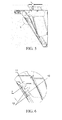
- the hook portion 3 further includes a handle portion 12, as shown in FIG. 3 , FIG. 5 and FIG. 6 .
- the handle portion 12 is clamped in the guide rail portion 10 and moves along the guide rail portion 10, so that the hook 11 moves along an axial direction of the shaft lever portion 7.
- the filter plate 1 touches the magnetic attraction portion 5, that is, the filter plate 1 and the fume collecting hood 2 are connected, the filter plate 1 is in a stable state.
- the "filter plate 1 being in a stable state” refers to that the filter plate 1 and the fume collecting hood 2 are firmly fixed together, and when the range hood is started and in a use state, the filter plate 1 does not shake relative to the fume collecting hood 2.
- the hook 11 is held against the connection portion 6, and the handle portion 12 is also held against the connection portion 6.
- the guide rail portion 10 is inclined relative to the handle portion 12, and therefore "the filter plate 1 is in a stable state". In fact, since the guide rail portion 10 is inclined relative to the handle portion 12, the above stable state can be achieved as long as one of the hook 11 and the handle portion 12 is held against the connection portion 6.
- the magnetic attraction portion 5 is clamped on the fume collecting hood 2.
- the magnetic attraction portion 5 includes a cylindrical portion 13, and a first bump 14 and a block ring 15 disposed on the cylindrical portion 13.
- a distance between the first bump 14 and the block ring 15 is slightly greater than the thickness of the fume collecting hood 2.
- a second bump 16 is disposed on the block ring 15 in a direction towards the first bump 14. Specifically, the second bump 16 and the first bump 14 are disposed in a way that the two are not opposite each other.
- a first through hole 17 and a second through hole 18 are opened on the fume collecting hood 2.
- the second through hole 18 is opened at the edge of the first through hole 17, that is, the second through hole 18 is in communication with the first through hole 17.
- the first through hole 17 is for the cylindrical portion 13 to pass through
- the second through hole 18 is for the first bump 14 to pass through.
- the number of the second through holes 18 and the number of the first bumps 14 are the same, and both are three or more.
- the number of the second bump 16 is one.
- the cylindrical portion 13 uses a hollow structure, and a magnet is disposed therein.
- FIG. 9 and FIG. 10 are schematic structural views when the magnet is not disposed.
- a through hole portion 19 is formed by an interval between the block ring 15 and the cylindrical portion 13.
- the second bump 16 is disposed at a position near the through hole portion 19.
- All components of the hook portion 3 are integrally formed, and all components of the support portion 4 are also integrally formed, which improves the manufacturing efficiency and reduces the manufacturing cost.
- the hook portion may also be disposed on the fume collecting hood, and the support portion may also be disposed on the filter plate.
- the magnetic attraction portion may also be disposed on the filter plate.
- the number of the first connection device(s) may be one, three or more.
- the number of the second connection device(s) may be one, three or more.
- the filter plate may also be disposed with an attracted portion, and the position of the attracted portion corresponds to the magnetic attraction portion on the fume collecting hood.
- the attracted portion is made of a material attractable by a magnet, and the parts of the filter plate other than the attracted portion may be made of other materials. Further, the technical solution of the present invention may also be applied to a top suction range hood. Further, the distance between the first bump and the block ring may be equal to the thickness of the fume collecting hood. At this time, the first bump, the block ring and the second bump are all made of a material with certain elasticity. Further, the number of the second through hole(s) and the first bump(s) may also be one, two, four or more.
Landscapes
- Engineering & Computer Science (AREA)
- Chemical & Material Sciences (AREA)
- Combustion & Propulsion (AREA)
- Mechanical Engineering (AREA)
- General Engineering & Computer Science (AREA)
- Ventilation (AREA)
- Filtering Of Dispersed Particles In Gases (AREA)
Applications Claiming Priority (1)
| Application Number | Priority Date | Filing Date | Title |
|---|---|---|---|
| CN201110201427.4A CN102878598B (zh) | 2011-07-13 | 2011-07-13 | 抽油烟机 |
Publications (1)
| Publication Number | Publication Date |
|---|---|
| EP2546578A1 true EP2546578A1 (en) | 2013-01-16 |
Family
ID=46456423
Family Applications (1)
| Application Number | Title | Priority Date | Filing Date |
|---|---|---|---|
| EP12174883A Withdrawn EP2546578A1 (en) | 2011-07-13 | 2012-07-04 | Range hood |
Country Status (2)
| Country | Link |
|---|---|
| EP (1) | EP2546578A1 (zh) |
| CN (1) | CN102878598B (zh) |
Cited By (17)
| Publication number | Priority date | Publication date | Assignee | Title |
|---|---|---|---|---|
| JP2014202439A (ja) * | 2013-04-08 | 2014-10-27 | 富士工業株式会社 | レンジフード |
| EP2840323A3 (en) * | 2013-08-14 | 2015-10-14 | Whirlpool Corporation | System and method for mounting undercabinet ventilation hood |
| EP3106760A1 (de) * | 2015-06-15 | 2016-12-21 | Miele & Cie. KG | Filtereinrichtung |
| EP3196556A1 (de) * | 2016-01-25 | 2017-07-26 | Miele & Cie. KG | Dunstabzugshaube |
| EP3222919A1 (de) * | 2016-03-23 | 2017-09-27 | BSH Hausgeräte GmbH | Dunstabzugshaube mit sichthaube und innenelement |
| CN107218636A (zh) * | 2017-08-04 | 2017-09-29 | 合肥宁致信息技术有限公司 | 一种方便使用的抽油烟机 |
| US9897331B2 (en) | 2013-05-29 | 2018-02-20 | Whirlpool Corporation | System and method for mounting undercabinet ventilation hood |
| US9897330B2 (en) | 2013-05-29 | 2018-02-20 | Whirlpool Corporation | System and method for mounting undercabinet ventilation hood |
| CN107975838A (zh) * | 2017-05-26 | 2018-05-01 | 宁波方太厨具有限公司 | 一种带有活动导烟板的吸油烟机 |
| CN109855131A (zh) * | 2017-11-30 | 2019-06-07 | 宁波方太厨具有限公司 | 一种进风口可封闭的顶吸式吸油烟机及其控制方法 |
| EP3524890A1 (de) * | 2017-12-15 | 2019-08-14 | Miele & Cie. KG | Aufnahmevorrichtung, befestigungselement, befestigungssystem, dunstabzugshaube, filter und dunstabzugshaubensystem |
| CN110207200A (zh) * | 2018-05-30 | 2019-09-06 | 华帝股份有限公司 | 用于吸油烟机的油网装置及吸油烟机 |
| CN113685866A (zh) * | 2021-08-10 | 2021-11-23 | 广东格兰仕集团有限公司 | 油烟机、烟灶联动系统以及油烟机的进风控制方法 |
| CN114110690A (zh) * | 2021-11-17 | 2022-03-01 | 河南中管环境科技研究院 | 一种油烟催化分解处理装置 |
| CN114353142A (zh) * | 2022-01-07 | 2022-04-15 | 杭州老板电器股份有限公司 | 一种集烟组件、吸油烟机及集烟组件的控制方法 |
| USD952828S1 (en) | 2020-07-28 | 2022-05-24 | Whirlpool Corporation | Vent hood |
| US11428419B2 (en) | 2020-07-28 | 2022-08-30 | Whirlpool Corporation | Vent hood assembly |
Families Citing this family (3)
| Publication number | Priority date | Publication date | Assignee | Title |
|---|---|---|---|---|
| CN103196166B (zh) * | 2013-03-07 | 2015-07-08 | 湖北酒总厨业有限公司 | 组合式油烟净化装置 |
| CN103644585B (zh) * | 2013-11-29 | 2016-04-27 | 中山市日顺厨卫有限公司 | 一种方便清洁的吸油烟机 |
| CN106468454B (zh) * | 2015-08-20 | 2020-12-01 | 博西华电器(江苏)有限公司 | 侧吸式抽油烟机 |
Citations (3)
| Publication number | Priority date | Publication date | Assignee | Title |
|---|---|---|---|---|
| EP1607686A1 (en) * | 2004-06-16 | 2005-12-21 | SIFIM S.r.l. | Kitchen hood filter with safety means for retaining the filter on the hood |
| EP1621819A2 (de) * | 2004-07-27 | 2006-02-01 | Miele & Cie. KG | Dunstabzugshaube |
| DE102004062684A1 (de) * | 2004-12-21 | 2006-06-22 | Langner, Manfred H. | Ablufthaube |
Family Cites Families (1)
| Publication number | Priority date | Publication date | Assignee | Title |
|---|---|---|---|---|
| CN201170627Y (zh) * | 2008-01-24 | 2008-12-24 | 宁波市万茂电器有限公司 | 一种近吸式油烟机 |
-
2011
- 2011-07-13 CN CN201110201427.4A patent/CN102878598B/zh not_active Expired - Fee Related
-
2012
- 2012-07-04 EP EP12174883A patent/EP2546578A1/en not_active Withdrawn
Patent Citations (3)
| Publication number | Priority date | Publication date | Assignee | Title |
|---|---|---|---|---|
| EP1607686A1 (en) * | 2004-06-16 | 2005-12-21 | SIFIM S.r.l. | Kitchen hood filter with safety means for retaining the filter on the hood |
| EP1621819A2 (de) * | 2004-07-27 | 2006-02-01 | Miele & Cie. KG | Dunstabzugshaube |
| DE102004062684A1 (de) * | 2004-12-21 | 2006-06-22 | Langner, Manfred H. | Ablufthaube |
Cited By (28)
| Publication number | Priority date | Publication date | Assignee | Title |
|---|---|---|---|---|
| JP2014202439A (ja) * | 2013-04-08 | 2014-10-27 | 富士工業株式会社 | レンジフード |
| US10240801B2 (en) | 2013-05-29 | 2019-03-26 | Whirlpool Corporation | System and method for mounting undercabinet ventilation hood |
| US10782031B2 (en) | 2013-05-29 | 2020-09-22 | Whirlpool Corporation | System and method for mounting undercabinet ventilation hood |
| US9897331B2 (en) | 2013-05-29 | 2018-02-20 | Whirlpool Corporation | System and method for mounting undercabinet ventilation hood |
| US9897330B2 (en) | 2013-05-29 | 2018-02-20 | Whirlpool Corporation | System and method for mounting undercabinet ventilation hood |
| US10018365B2 (en) | 2013-05-29 | 2018-07-10 | Whirlpool Corporation | System and method for mounting undercabinet ventilation hood |
| EP2840323A3 (en) * | 2013-08-14 | 2015-10-14 | Whirlpool Corporation | System and method for mounting undercabinet ventilation hood |
| US9523507B2 (en) | 2013-08-14 | 2016-12-20 | Whirlpool Corporation | Method for mounting undercabinet ventilation hood |
| US10948200B2 (en) | 2013-08-14 | 2021-03-16 | Whirlpool Corporation | System for mounting undercabinet ventilation hood |
| US10317093B2 (en) | 2013-08-14 | 2019-06-11 | Whirlpool Corporation | System for mounting undercabinet ventilation hood |
| EP3106760A1 (de) * | 2015-06-15 | 2016-12-21 | Miele & Cie. KG | Filtereinrichtung |
| EP3196556A1 (de) * | 2016-01-25 | 2017-07-26 | Miele & Cie. KG | Dunstabzugshaube |
| EP3222919A1 (de) * | 2016-03-23 | 2017-09-27 | BSH Hausgeräte GmbH | Dunstabzugshaube mit sichthaube und innenelement |
| EP3904772A1 (de) * | 2016-03-23 | 2021-11-03 | BSH Hausgeräte GmbH | Dunstabzugshaube mit sichthaube und innenelement |
| CN107975838A (zh) * | 2017-05-26 | 2018-05-01 | 宁波方太厨具有限公司 | 一种带有活动导烟板的吸油烟机 |
| CN107975838B (zh) * | 2017-05-26 | 2024-02-20 | 宁波方太厨具有限公司 | 一种带有活动导烟板的吸油烟机 |
| CN107218636A (zh) * | 2017-08-04 | 2017-09-29 | 合肥宁致信息技术有限公司 | 一种方便使用的抽油烟机 |
| CN109855131A (zh) * | 2017-11-30 | 2019-06-07 | 宁波方太厨具有限公司 | 一种进风口可封闭的顶吸式吸油烟机及其控制方法 |
| CN109855131B (zh) * | 2017-11-30 | 2024-01-16 | 宁波方太厨具有限公司 | 一种进风口可封闭的顶吸式吸油烟机及其控制方法 |
| EP3524890A1 (de) * | 2017-12-15 | 2019-08-14 | Miele & Cie. KG | Aufnahmevorrichtung, befestigungselement, befestigungssystem, dunstabzugshaube, filter und dunstabzugshaubensystem |
| CN110207200A (zh) * | 2018-05-30 | 2019-09-06 | 华帝股份有限公司 | 用于吸油烟机的油网装置及吸油烟机 |
| USD952828S1 (en) | 2020-07-28 | 2022-05-24 | Whirlpool Corporation | Vent hood |
| US11428419B2 (en) | 2020-07-28 | 2022-08-30 | Whirlpool Corporation | Vent hood assembly |
| USD1011505S1 (en) | 2020-07-28 | 2024-01-16 | Whirlpool Corporation | Vent hood |
| CN113685866A (zh) * | 2021-08-10 | 2021-11-23 | 广东格兰仕集团有限公司 | 油烟机、烟灶联动系统以及油烟机的进风控制方法 |
| CN114110690A (zh) * | 2021-11-17 | 2022-03-01 | 河南中管环境科技研究院 | 一种油烟催化分解处理装置 |
| CN114110690B (zh) * | 2021-11-17 | 2024-04-05 | 河南中管环境科技研究院 | 一种油烟催化分解处理装置 |
| CN114353142A (zh) * | 2022-01-07 | 2022-04-15 | 杭州老板电器股份有限公司 | 一种集烟组件、吸油烟机及集烟组件的控制方法 |
Also Published As
| Publication number | Publication date |
|---|---|
| CN102878598B (zh) | 2016-05-11 |
| CN102878598A (zh) | 2013-01-16 |
Similar Documents
| Publication | Publication Date | Title |
|---|---|---|
| EP2546578A1 (en) | Range hood | |
| AU2017281474B2 (en) | Insert for a downdraft extractor | |
| EP2868983A1 (en) | Range hood | |
| CN104566575B (zh) | 吸油烟机 | |
| US11248805B2 (en) | Air filter for grease filtering | |
| CN110384988A (zh) | 空气清洁器 | |
| US20230296263A1 (en) | Extraction device with filter carrier and filter | |
| JP5060255B2 (ja) | レンジフード | |
| IT201800003993A1 (it) | Involucro di una cappa per l’aspirazione di fumi di cottura | |
| KR200460957Y1 (ko) | 천정용 공조기의 흡입그릴 설치구조 | |
| JP2011179691A (ja) | 排気口カバー取付具 | |
| CN205375288U (zh) | 防尘罩及电子设备 | |
| JP6535877B2 (ja) | レンジフード | |
| US20160271553A1 (en) | Multi-stage hood filter | |
| TW202311674A (zh) | 油捕集裝置、抽油煙機以及空氣淨化器 | |
| JP2020500621A5 (zh) | ||
| CN209295251U (zh) | 油网安装结构及油烟机 | |
| JP6108669B2 (ja) | ベルマウスの取付構造およびレンジフード | |
| JP2014018701A (ja) | 落し込みケーシング用フィルタ枠 | |
| JP2016048165A (ja) | レンジフード | |
| WO2017044834A1 (en) | Noise reduction in cooking system | |
| JP6654174B2 (ja) | 換気装置 | |
| JP3446417B2 (ja) | ホットプレート | |
| CN103322604B (zh) | 抽油烟机 | |
| CN210951448U (zh) | 一种侧吸式吸油烟机 |
Legal Events
| Date | Code | Title | Description |
|---|---|---|---|
| PUAI | Public reference made under article 153(3) epc to a published international application that has entered the european phase |
Free format text: ORIGINAL CODE: 0009012 |
|
| AK | Designated contracting states |
Kind code of ref document: A1 Designated state(s): AL AT BE BG CH CY CZ DE DK EE ES FI FR GB GR HR HU IE IS IT LI LT LU LV MC MK MT NL NO PL PT RO RS SE SI SK SM TR |
|
| AX | Request for extension of the european patent |
Extension state: BA ME |
|
| 17P | Request for examination filed |
Effective date: 20130716 |
|
| RBV | Designated contracting states (corrected) |
Designated state(s): AL AT BE BG CH CY CZ DE DK EE ES FI FR GB GR HR HU IE IS IT LI LT LU LV MC MK MT NL NO PL PT RO RS SE SI SK SM TR |
|
| RAP1 | Party data changed (applicant data changed or rights of an application transferred) |
Owner name: BSH HAUSGERAETE GMBH |
|
| 17Q | First examination report despatched |
Effective date: 20170223 |
|
| GRAP | Despatch of communication of intention to grant a patent |
Free format text: ORIGINAL CODE: EPIDOSNIGR1 |
|
| INTG | Intention to grant announced |
Effective date: 20190717 |
|
| STAA | Information on the status of an ep patent application or granted ep patent |
Free format text: STATUS: THE APPLICATION IS DEEMED TO BE WITHDRAWN |
|
| 18D | Application deemed to be withdrawn |
Effective date: 20191128 |