EP2545766A1 - Reststoffabblas- und/oder -ansaugvorrichtung - Google Patents
Reststoffabblas- und/oder -ansaugvorrichtung Download PDFInfo
- Publication number
- EP2545766A1 EP2545766A1 EP11174014A EP11174014A EP2545766A1 EP 2545766 A1 EP2545766 A1 EP 2545766A1 EP 11174014 A EP11174014 A EP 11174014A EP 11174014 A EP11174014 A EP 11174014A EP 2545766 A1 EP2545766 A1 EP 2545766A1
- Authority
- EP
- European Patent Office
- Prior art keywords
- volute
- appliance
- impeller
- fluid
- debris
- Prior art date
- Legal status (The legal status is an assumption and is not a legal conclusion. Google has not performed a legal analysis and makes no representation as to the accuracy of the status listed.)
- Granted
Links
- 238000007664 blowing Methods 0.000 title claims abstract description 14
- 239000012530 fluid Substances 0.000 claims abstract description 55
- 239000002362 mulch Substances 0.000 claims description 3
- 239000010921 garden waste Substances 0.000 description 8
- 230000004888 barrier function Effects 0.000 description 3
- 230000000295 complement effect Effects 0.000 description 2
- 238000000926 separation method Methods 0.000 description 2
- 239000002699 waste material Substances 0.000 description 2
- 239000004677 Nylon Substances 0.000 description 1
- 241001417527 Pempheridae Species 0.000 description 1
- 230000009286 beneficial effect Effects 0.000 description 1
- 230000008901 benefit Effects 0.000 description 1
- 238000004140 cleaning Methods 0.000 description 1
- 238000002485 combustion reaction Methods 0.000 description 1
- 239000002828 fuel tank Substances 0.000 description 1
- 238000003780 insertion Methods 0.000 description 1
- 230000037431 insertion Effects 0.000 description 1
- 230000003993 interaction Effects 0.000 description 1
- 239000000463 material Substances 0.000 description 1
- 238000012986 modification Methods 0.000 description 1
- 230000004048 modification Effects 0.000 description 1
- 229920001778 nylon Polymers 0.000 description 1
- 239000002245 particle Substances 0.000 description 1
- 230000037361 pathway Effects 0.000 description 1
- 239000004033 plastic Substances 0.000 description 1
- 238000011144 upstream manufacturing Methods 0.000 description 1
Images

Classifications
-
- A—HUMAN NECESSITIES
- A47—FURNITURE; DOMESTIC ARTICLES OR APPLIANCES; COFFEE MILLS; SPICE MILLS; SUCTION CLEANERS IN GENERAL
- A47L—DOMESTIC WASHING OR CLEANING; SUCTION CLEANERS IN GENERAL
- A47L5/00—Structural features of suction cleaners
- A47L5/12—Structural features of suction cleaners with power-driven air-pumps or air-compressors, e.g. driven by motor vehicle engine vacuum
- A47L5/14—Structural features of suction cleaners with power-driven air-pumps or air-compressors, e.g. driven by motor vehicle engine vacuum cleaning by blowing-off, also combined with suction cleaning
-
- A—HUMAN NECESSITIES
- A01—AGRICULTURE; FORESTRY; ANIMAL HUSBANDRY; HUNTING; TRAPPING; FISHING
- A01G—HORTICULTURE; CULTIVATION OF VEGETABLES, FLOWERS, RICE, FRUIT, VINES, HOPS OR SEAWEED; FORESTRY; WATERING
- A01G20/00—Cultivation of turf, lawn or the like; Apparatus or methods therefor
- A01G20/40—Apparatus for cleaning the lawn or grass surface
- A01G20/43—Apparatus for cleaning the lawn or grass surface for sweeping, collecting or disintegrating lawn debris
- A01G20/47—Vacuum or blower devices
-
- F—MECHANICAL ENGINEERING; LIGHTING; HEATING; WEAPONS; BLASTING
- F04—POSITIVE - DISPLACEMENT MACHINES FOR LIQUIDS; PUMPS FOR LIQUIDS OR ELASTIC FLUIDS
- F04D—NON-POSITIVE-DISPLACEMENT PUMPS
- F04D29/00—Details, component parts, or accessories
- F04D29/40—Casings; Connections of working fluid
- F04D29/42—Casings; Connections of working fluid for radial or helico-centrifugal pumps
- F04D29/4206—Casings; Connections of working fluid for radial or helico-centrifugal pumps especially adapted for elastic fluid pumps
- F04D29/4226—Fan casings
-
- F—MECHANICAL ENGINEERING; LIGHTING; HEATING; WEAPONS; BLASTING
- F04—POSITIVE - DISPLACEMENT MACHINES FOR LIQUIDS; PUMPS FOR LIQUIDS OR ELASTIC FLUIDS
- F04D—NON-POSITIVE-DISPLACEMENT PUMPS
- F04D29/00—Details, component parts, or accessories
- F04D29/40—Casings; Connections of working fluid
- F04D29/42—Casings; Connections of working fluid for radial or helico-centrifugal pumps
- F04D29/44—Fluid-guiding means, e.g. diffusers
- F04D29/441—Fluid-guiding means, e.g. diffusers especially adapted for elastic fluid pumps
-
- F—MECHANICAL ENGINEERING; LIGHTING; HEATING; WEAPONS; BLASTING
- F05—INDEXING SCHEMES RELATING TO ENGINES OR PUMPS IN VARIOUS SUBCLASSES OF CLASSES F01-F04
- F05D—INDEXING SCHEME FOR ASPECTS RELATING TO NON-POSITIVE-DISPLACEMENT MACHINES OR ENGINES, GAS-TURBINES OR JET-PROPULSION PLANTS
- F05D2250/00—Geometry
- F05D2250/50—Inlet or outlet
- F05D2250/52—Outlet
Definitions
- the present invention relates to a blower vacuum, vacuum or blower appliance. More particularly, the present invention relates to a blower vacuum, vacuum or blower appliance having improved efficiency.
- blower vacuum appliances comprise a motor and fan arrangement.
- the motor is usually either petrol or electrically powered.
- the fan comprises a centrifugal impeller enclosed within a toroidal enclosure known as a volute.
- the impeller is configured, in use, to draw air in along the axis of rotation of the centrifugal impeller and expel air out radially.
- the volute comprises a fluid inlet surrounding the eye of the impeller and aligned with axis of rotation of the impeller, and a fluid outlet located at a point on the periphery of the volute.
- the shape of the volute essentially directs the radially-moving air towards the fluid outlet.
- Blower vacuum appliances generally have two modes of operation: blowing and vacuuming.
- blowing mode clean air is drawn into the volute from the atmosphere via the fluid inlet and is expelled via the fluid outlet.
- a blower tube is attached to the outlet in order to focus and direct the expelled air into a jet. This jet of air may be aimed through manipulation of the blower tube or blower vacuum to move or gather garden waste.
- a suction tube having a suction inlet is connected to the fluid inlet of the volute and a debris collector (which may comprise separation means such as a semiporous bag or container) for garden waste is attached in direct fluid connection to the fluid outlet of the volute. Therefore, in this arrangement, the fan is located directly in the flowpath from the suction inlet to the debris collector. Consequently, garden waste or debris entrained in the air passing into the suction inlet passes through the fluid inlet of the volute and collides with the fan before being passed via the fluid outlet of the volute into the debris collector.
- This arrangement enables garden waste or debris to be broken down or mulched into smaller particles for efficient collection in the debris collector.
- a debris collector (which may comprise separation means such as a semi-porous bag or container) for garden waste is also attached in direct fluid connection to the fluid outlet of the volute.
- a suction tube comprising a suction inlet is connected downstream of the fluid outlet of the volute.
- This arrangement has the advantage that the fan is supplied with a clean stream of air at all times and so can operate under optimal conditions with relatively little chance of blockages forming.
- An alternative arrangement of device is simply a blower appliance without a vacuum function.
- This arrangement operates in the same manner as the blower mode of the clean-fan arrangement. Clean air is drawn into a volute from the atmosphere via afluid inlet and is expelled via a fluid outlet.
- a blower tube attached to the fluid outlet focuses and directs the expelled air into a jet. This jet of air may be aimed through manipulation of the blower tube or blower vacuum to move or gather garden waste.
- Blower vacuum and/or blower appliances are often required to generate high flow rates of air through the impeller to produce a powerful jet of air (in the blower mode) or powerful suction (in the vacuum mode, where appropriate) in order to clear an external environment of debris and waste. Therefore, it is beneficial to minimise losses in the appliance in order to maximise the available airflow.
- a volute arrangement comprising a centrifugal impeller
- air is directed through the eye of the impeller and is then directed radially outwardly therefrom. From the outlet of the impeller, the airflow passes into a volute which directs the airflow to an outlet.
- the location of the impeller with regard to the walls of the volute mean that the pressure distribution created at the outlet to the impeller may not be constant. This reduces the efficiency of the impeller.
- a debris blowing and/or vacuum appliance comprising a body including: a fluid inlet; a fluid outlet for exhausting fluid externally of the body; a volute located in a flowpath between the fluid inlet and the fluid outlet; and a centrifugal impeller located within the volute and rotatable by a motor to generate a flow of fluid between the fluid inlet and the fluid outlet, the volute comprising: volute walls delimiting a volute outlet region in communication with the fluid outlet; and a diffuser located immediately downstream of the centrifugal impeller between the centrifugal impeller and the volute outlet region, the diffuser comprising an annular channel surrounding the centrifugal impeller and having substantially constant radial width such that the impeller is radially spaced from the volute walls by at least the width of the diffuser.
- the efficiency of the impeller can be improved.
- the use of such a diffuser configuration in an appliance enables the pressure drop across the impeller to be substantially even around the circumference thereof, improving the performance of the impeller.
- this enables a greater airflow to be supplied per unit of supplied power. Therefore, an appliance having improved performance for blowing and/or vacuuming dirt and debris can be provided without, for example, increasing power consumption. This is of relevance to battery powered appliances, where improved efficiency may provide stronger performance and a longer operating run time for a given battery size and charge.
- the diffuser is vaneless.
- a vaneless diffuser is particularly efficient for guiding an airflow from an impeller to the volute outlet region.
- the diffuser comprises planar annular walls defining the annular channel. By providing planar annular walls, losses in the diffuser are minimised.
- the volute walls define a volute outlet region having an expanding cross-sectional area in the downstream direction.
- the cross-sectional area increases smoothly in the downstream direction. This arrangement reduces losses due to sudden volume changes as the air moves downstream of the impeller.
- volute walls define a scroll-type volute outlet region having a substantially circular cross section. Such an arrangement provides an efficient configuration with reduced losses.
- the volute outlet region further comprises a tangential portion extending downstream towards the fluid outlet.
- the volute further comprises a volute tongue delimiting at least a part of the tangential portion.
- the volute tongue is radially spaced from the impeller by a distance at least equal to the width of the diffuser.
- the appliance is in the form of a vacuum appliance or a combined debris blowing and vacuum appliance, wherein the fluid inlet comprises a suction inlet arranged, in use, to draw dirt and debris therethrough.
- a vacuum appliance or a combined debris blowing and vacuum appliance
- the fluid inlet comprises a suction inlet arranged, in use, to draw dirt and debris therethrough.
- the appliance further comprises a suction tube, the suction inlet being located at a distal end of the suction tube.
- the suction tube enables a dire- and debris-entrained stream of air to be drawn efficiently into the appliance.
- the centrifugal impeller is arranged, in use, to receive and to mulch dirt and debris drawn in through the suction inlet.
- dirt and debris can be mulched (i.e. broken up) by the impeller into smaller sections. This enables the dirt and debris leaving the appliance to be packed more tightly and efficiently.
- the appliance further comprises a debris collector located downstream of the fluid outlet and arranged, in use, to collect dirt and debris drawn in through the suction inlet. This enables the dirt and debris drawn into the appliance to be captured securely for disposal.
- the appliance is in the form of a debris blowing appliance and further comprises a blower tube, the fluid outlet being located at a distal end of the blower tube.
- the blower tube enables a concentrated stream of air to be directed accurately as required by a user of the appliance.
- the present invention provides an impeller and volute arrangement which reduces inlet losses to the impeller when compared to known arrangements.
- Barrier means provided on the shroud of an impeller are located in close relationship with a complementary portion of the volute adjacent the air inlet.
- FIG 1 shows an example of a blower (or sweeper) appliance 10 in which embodiments of the present invention may be used.
- the blower appliance 10 is an electrically-powered appliance which comprises a battery pack.
- the blower appliance 10 may be mains-powered or comprise an internal combustion engine and fuel tank.
- the blower appliance 10 comprises a body 12 which may be formed from a hardened plastic material.
- the body 12 comprises a volute 14 and a graspable handle 16.
- a removable power source 18 (in the form of a battery pack) is located at the base of the handle 16.
- the volute 14 is essentially disc shaped and houses a motor and impeller arrangement (not shown in Figure 1 ) for generating an airflow through the blower appliance 10.
- the volute 14 comprises an air inlet 20 located at the centre of the disc-shaped volute 14 and an air outlet 22 extending tangentially away from the disc shaped portion of the volute 14.
- the impeller is operable to draw an airflow through the air inlet 20 and exhaust the airflow through the air outlet 22.
- the air inlet 20, as shown, is covered by a grille or cover 24 which prevents a user contacting rotating parts located therein.
- the spacing of the grille 24 is such to prevent insertion of a human finger according to safety standard UL-1017 of Underwriters' Laboratory Inc..
- a detachable blower tube 26 is connected to the air outlet 22 and comprises an exhaust outlet 28 at a distal end thereof.
- the blower tube 26 narrows from the adjacent the air outlet 22 to the exhaust outlet 28 to focus and direct the airflow into a powerful jet.
- a blower vacuum appliance 30 is shown in Figure 2 in which embodiments of the present invention may be used.
- the blower vacuum appliance 30 is similar in configuration to the blower appliance 10 of Figure 1 and is an electrically-powered appliance which comprises a battery pack.
- the blower vacuum appliance 30 comprises a body 32 comprising a volute 34 and a graspable handle 36.
- a removable power source 38 (in the form of a battery pack) is located at the base of the handle 36.
- the volute 14 is essentially the same as that of the blower appliance 10 and houses a motor and impeller arrangement (not shown in Figure 2 ) for generating an airflow through the blower vacuum appliance 30.
- the blower vacuum appliance 30 is a dirty-fan arrangement and so the impeller is configured to receive debris and mulch the debris.
- the volute 34 comprises an air inlet 40 located at the centre of the disc-shaped volute 34 and an air outlet 42 extending tangentially away from the disc shaped portion of the volute 34.
- a suction tube 44 is connected to the air inlet 40 and comprises a suction inlet 46 at a distal end thereof.
- the suction tube 44 is configured to draw air and entrained debris through the suction inlet 46 and into the volute 34 where the debris is mulched.
- a debris collector 48 is connected directly to the air outlet 42 and provides a collection receptacle for the mulched debris passed through the volute 34.
- the debris collector 48 is semi-porous so that air can escape therethrough and may comprise, for example, a nylon bag or other collection means.
- the blower vacuum appliance 30 as described above is shown in a vacuum mode of operation.
- the suction tube 44 can be detached and connected to the air outlet 42 in the manner of the blower appliance 10.
- a grille (not shown) can then be connected to the air inlet.
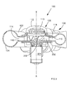
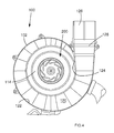
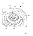
- Figures 3 to 7 show the arrangement according to the present invention.
- Figures 3 to 7 shows a section through a volute assembly 100 according to an embodiment of the present invention.
- the volute assembly 100 comprises first and second clamshell portions 102, 104.
- the clamshell portions 102, 104 define a central hub 106 and a scroll portion 108 located outwardly of the hub 106.
- the hub 106 comprises an air inlet 110 located centrally at an upper portion thereof.
- the air inlet 110 is covered by a grille 112.
- An impeller 200 is located at the centre of the hub 106 in communication with the air inlet 110.
- the impeller 200 is mounted on a drive shaft 202 connected to a motor 204.
- the impeller 200 in use, is operable to rotate on the drive shaft 202 about an axis X-X which is coincident with the centre of the hub 106.
- a diffuser 114 is located radially outwardly, and downstream, of the impeller 200 and comprises an annular channel delimited by two diffuser walls 116, 118.
- the diffuser 114 is located between the hub 106 and the scroll portion 108 of the volute 100 and has a narrower height that either the hub 106 or the scroll region 108.
- the diffuser 114 is vaneless. That is to say no vanes, projections or guides are located in the annular channel comprising the diffuser 114 and the diffuser 114 essentially comprises a substantially smooth annular channel defined by the two planar, spaced apart annular walls 116, 118.
- the diffuser 114 is symmetrical about the axis X-X and has a constant height and width.
- the scroll portion 108 is located in the flowpath immediately downstream of the diffuser 114.
- the scroll portion 108 comprises a spiral, scroll cavity 120 defined by volute walls 122.
- the volute walls 122 have a circular cross section which increases smoothly in diameter in an anticlockwise direction (as shown in Figure 4 ) from a position adjacent a volute tongue 124 located adjacent the outer portion of the diffuser 114 to terminate in an air outlet 126.
- the cross-sectional area of the volute outlet portion increases smoothly and constantly in the downstream direction towards the air outlet 126.
- the air outlet 126 is formed at a distal end of a tangential section 128 of the scroll portion 108. As shown in Figure 4 , the volute tongue 124 delimits a portion of the tangential section 128 leading to the air outlet 126.
- the diffuser 114 functions to space the impeller 200 radially from the walls 122 of the scroll cavity 120.
- the impeller 200 is spaced radially from the walls 122 by at least the width of the diffuser walls 116, 118. This arrangement ensures that the pressure distribution at the outlet of the impeller 200 is substantially constant around the circumference of the impeller 200. This prevents localised pressure variations, improving the efficiency of the impeller 200.
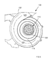
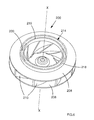
- the impeller 200 will now be described in detail with reference to Figures 6 to 8 .
- the impeller 200 is shown removed from the volute arrangement 100.
- the impeller 200 is shown located on the lower clamshell portion 104 with the upper clamshell portion 102 removed.
- the impeller 200 includes a base 206, a shroud 208 and a plurality of fan blades 210 located therebetween.
- the base 206 extends radially from the axis X-X of the drive shaft 202 parallel to the diffuser 114.
- the fan blades 210 extend perpendicularly from the base 206 and are curved for aerodynamic efficiency.
- the shroud 208 delimits an axially-arranged inlet 212 to the eye of the impeller 200. When fitted in the volute 100, the inlet 212 to the impeller 200 is co-axial with, and located adjacent, the air inlet 110 formed in the hub 106 of the volute 100.
- the shroud 208 comprises barrier means 214 located on a surface thereof facing away from the base 206.
- the barrier means 214 comprise two annular ribs 216, 218 which project away from the shroud 208 and surround the inlet 212.
- the innermost annular rib 216 forms a part of the boundary wall delimiting the inlet 212.
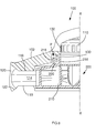
- FIG. 8 shows a cross-sectional view (similar to Figure 3 ) through the volute 100 showing the impeller located in the hub 106 of the volute 100.
- a complementary annular volute rib 128 is formed on the inner surface of the wall of the hub 106 of the volute 100.
- the annular volute rib 128 extends into the annular channel 220 formed by the annular ribs 216, 218, defining a convoluted or labyrinthine path from the air inlet 110 through the annular channel 220.
- the volute rib 128 is spaced from the annular ribs 216, 218 in both axial and radial directions to ensure that, in use, tolerances are sufficient to prevent contact between the volute rib 128 and the annular ribs 216, 218 (which will be rotating with the impeller 200).
- an internal inlet wall 130 of the inlet 110 is located at the same radial spacing as the inner annular wall 216 to define an essentially smooth (with the exception of the necessary axial spacing between the annular wall 216 and the internal inlet wall 130) inlet flowpath for air entering the inlet 110 and passing through the inlet 212 into the eye of the impeller 200.
- the drive shaft 202 When the motor 204 is activated by a user, the drive shaft 202 will be caused to rotate.
- the impeller 200 which is secured to the drive shaft 202, will also be caused to be rotated.
- an airflow is drawn in through the volute inlet 110 and through the inlet 212 of the impeller 200.
- the air is then guided onto the fan blades 210 where it is accelerated and dispersed radially outwardly by the fan blades 210.
- This causes a pressure drop across the impeller 200 since the air downstream of the impeller 200 is moving faster than the upstream airflow. This, in turn, causes further air to be drawn into the volute inlet 110 and into the impeller 200.
- the pressure drop at the outlet of the impeller may not be substantially constant around the circumference of the impeller. This is due to the varying radial distance between the outlet of the impeller and the walls of the volute in conventional arrangements. This reduces the efficiency of the impeller.
- the provision of the vaneless diffuser 114 provides a constant-width outlet region with no projections or unnecessary contact surfaces to disturb the airflow exiting the impeller.
- the pressure drop at the impeller outlet is, thus, substantially constant around the circumference of the impeller 200.
- the impeller 200 is able to operate at a high efficiency.
- the airflow then passes through the fan blades 210, across the diffuser 114 and is exhausted into the scroll portion 108 of the volute 100.
- the airflow is then directed around the volute walls 122 towards the tangential portion 128 and through the air outlet 126.
- blower or blower vacuum appliances generally for use in a domestic environment
- the invention is readily applicable to other machines comprising centrifugal impellers.
- the present invention is equally applicable to a domestic or industrial vacuum cleaner.
Landscapes
- Engineering & Computer Science (AREA)
- Mechanical Engineering (AREA)
- General Engineering & Computer Science (AREA)
- Life Sciences & Earth Sciences (AREA)
- Environmental Sciences (AREA)
- Structures Of Non-Positive Displacement Pumps (AREA)
Priority Applications (5)
| Application Number | Priority Date | Filing Date | Title |
|---|---|---|---|
| EP11174014.8A EP2545766B1 (de) | 2011-07-14 | 2011-07-14 | Reststoffabblas- und/oder -ansaugvorrichtung |
| CA2782888A CA2782888C (en) | 2011-07-14 | 2012-07-11 | A debris blowing and/or vacuum appliance |
| AU2012205132A AU2012205132B2 (en) | 2011-07-14 | 2012-07-13 | A debris blowing and/or vacuum appliance |
| CN201210245927.2A CN102878115B (zh) | 2011-07-14 | 2012-07-16 | 碎屑吹扫和/或抽吸装置 |
| US13/549,742 US20130017079A1 (en) | 2011-07-14 | 2012-07-16 | Debris blowing and/or vacuum appliance |
Applications Claiming Priority (1)
| Application Number | Priority Date | Filing Date | Title |
|---|---|---|---|
| EP11174014.8A EP2545766B1 (de) | 2011-07-14 | 2011-07-14 | Reststoffabblas- und/oder -ansaugvorrichtung |
Publications (2)
| Publication Number | Publication Date |
|---|---|
| EP2545766A1 true EP2545766A1 (de) | 2013-01-16 |
| EP2545766B1 EP2545766B1 (de) | 2014-07-09 |
Family
ID=44510744
Family Applications (1)
| Application Number | Title | Priority Date | Filing Date |
|---|---|---|---|
| EP11174014.8A Active EP2545766B1 (de) | 2011-07-14 | 2011-07-14 | Reststoffabblas- und/oder -ansaugvorrichtung |
Country Status (5)
| Country | Link |
|---|---|
| US (1) | US20130017079A1 (de) |
| EP (1) | EP2545766B1 (de) |
| CN (1) | CN102878115B (de) |
| AU (1) | AU2012205132B2 (de) |
| CA (1) | CA2782888C (de) |
Cited By (1)
| Publication number | Priority date | Publication date | Assignee | Title |
|---|---|---|---|---|
| EP4203758A4 (de) * | 2020-09-23 | 2024-03-06 | Globe Jiangsu Co Ltd | Gebläseanordnung und staubsauger mit gebläseanordnung |
Families Citing this family (17)
| Publication number | Priority date | Publication date | Assignee | Title |
|---|---|---|---|---|
| CN104154008B (zh) * | 2013-05-13 | 2017-10-10 | 创科户外产品技术有限公司 | 鼓风机/真空吸尘装置 |
| AU2014202503B2 (en) * | 2013-05-13 | 2018-01-18 | Techtronic Outdoor Products Technology Limited | Blower/vacuum device |
| USD751685S1 (en) * | 2013-08-06 | 2016-03-15 | Shinano Kenshi Co., Ltd. | Blower |
| CN104454633A (zh) * | 2013-09-13 | 2015-03-25 | 博西华电器(江苏)有限公司 | 吸油烟机及其风机系统 |
| IN2013CH03755A (de) * | 2013-11-26 | 2015-09-11 | Ranga Krishna Kumar Bindingnavale | |
| CN104746458A (zh) * | 2013-12-27 | 2015-07-01 | 苏州宝时得电动工具有限公司 | 吹风装置 |
| CN104214117B (zh) * | 2014-09-02 | 2017-01-11 | 安庆市恒昌机械制造有限责任公司 | 吸废风机 |
| DE102015001811A1 (de) * | 2015-02-12 | 2016-08-18 | Andreas Stihl Ag & Co. Kg | Saug-/Blasgerät |
| US10473113B2 (en) * | 2015-12-16 | 2019-11-12 | Denso Corporation | Centrifugal blower |
| JP6634929B2 (ja) * | 2015-12-16 | 2020-01-22 | 株式会社デンソー | 遠心送風機 |
| JP2019018190A (ja) * | 2017-07-21 | 2019-02-07 | 株式会社マキタ | 送風作業機 |
| CN107307805A (zh) * | 2017-08-18 | 2017-11-03 | 宁波杨子电器有限公司 | 吸尘器 |
| DE102017122987A1 (de) * | 2017-10-04 | 2019-04-04 | Ebm-Papst Mulfingen Gmbh & Co. Kg | Halbspiralgehäuse |
| CN109645834B (zh) * | 2017-10-11 | 2023-12-19 | 佛山市顺德区美的电热电器制造有限公司 | 物料清洗容器和烹饪器具 |
| CN108423595A (zh) * | 2018-02-11 | 2018-08-21 | 浙江舞台设计研究院有限公司 | 一种举升装置 |
| CN110295564B (zh) * | 2019-07-04 | 2024-05-10 | 宁波创跃园林工具有限公司 | 一种吹吸机 |
| WO2021262952A1 (en) * | 2020-06-24 | 2021-12-30 | Milwaukee Electric Tool Corporation | Vacuum cleaner with liquid retention |
Citations (4)
| Publication number | Priority date | Publication date | Assignee | Title |
|---|---|---|---|---|
| GB519630A (en) * | 1938-09-22 | 1940-04-02 | Alfred Whitaker | Improvements in or relating to vacuum cleaners |
| US5443362A (en) * | 1994-03-16 | 1995-08-22 | The Hoover Company | Air turbine |
| WO2001024676A2 (en) * | 1999-09-28 | 2001-04-12 | Royal Appliance Mfg. Co. | Impeller and housing assembly with reduced noise and improved airflow |
| DE19959344A1 (de) * | 1999-12-09 | 2001-06-13 | Stihl Maschf Andreas | Radialgebläse |
Family Cites Families (11)
| Publication number | Priority date | Publication date | Assignee | Title |
|---|---|---|---|---|
| US3924291A (en) * | 1973-09-17 | 1975-12-09 | Hoover Co | Blower connection and exhaust valve configuration for a cleaner or the like |
| US4120616A (en) * | 1975-10-06 | 1978-10-17 | Breuer Electric Manufacturing Company | Vacuum cleaner-blower assembly with sound absorbing arrangement |
| US4325163A (en) * | 1980-04-07 | 1982-04-20 | Allegretti & Company | Portable blower-vacuum unit |
| JPH0886299A (ja) * | 1994-09-16 | 1996-04-02 | Nippondenso Co Ltd | 遠心式送風機 |
| US5768749A (en) * | 1996-07-26 | 1998-06-23 | Ryobi North America, Inc. | Portable air blower |
| DE19833837C2 (de) * | 1998-07-28 | 2002-06-27 | Stihl Maschf Andreas | Handgeführtes Saug-/Blasgerät |
| GB0313143D0 (en) * | 2003-06-07 | 2003-07-09 | Boc Group Plc | Sewage aeration |
| US7001140B2 (en) * | 2003-12-30 | 2006-02-21 | Acoustiflo, Ltd. | Centrifugal fan diffuser |
| DE102005007298B4 (de) * | 2005-02-17 | 2015-01-22 | Andreas Stihl Ag & Co. Kg | Handgeführtes, tragbares Saug-/Blasgerät |
| EP1731070A1 (de) * | 2005-06-10 | 2006-12-13 | Samsung Electronics Co., Ltd. | Gebläse und Staubsauger mit demselben |
| CN101205928B (zh) * | 2006-12-05 | 2012-06-13 | 安德烈亚斯·斯蒂尔两合公司 | 手持式鼓风机 |
-
2011
- 2011-07-14 EP EP11174014.8A patent/EP2545766B1/de active Active
-
2012
- 2012-07-11 CA CA2782888A patent/CA2782888C/en not_active Expired - Fee Related
- 2012-07-13 AU AU2012205132A patent/AU2012205132B2/en not_active Ceased
- 2012-07-16 CN CN201210245927.2A patent/CN102878115B/zh not_active Expired - Fee Related
- 2012-07-16 US US13/549,742 patent/US20130017079A1/en not_active Abandoned
Patent Citations (4)
| Publication number | Priority date | Publication date | Assignee | Title |
|---|---|---|---|---|
| GB519630A (en) * | 1938-09-22 | 1940-04-02 | Alfred Whitaker | Improvements in or relating to vacuum cleaners |
| US5443362A (en) * | 1994-03-16 | 1995-08-22 | The Hoover Company | Air turbine |
| WO2001024676A2 (en) * | 1999-09-28 | 2001-04-12 | Royal Appliance Mfg. Co. | Impeller and housing assembly with reduced noise and improved airflow |
| DE19959344A1 (de) * | 1999-12-09 | 2001-06-13 | Stihl Maschf Andreas | Radialgebläse |
Cited By (1)
| Publication number | Priority date | Publication date | Assignee | Title |
|---|---|---|---|---|
| EP4203758A4 (de) * | 2020-09-23 | 2024-03-06 | Globe Jiangsu Co Ltd | Gebläseanordnung und staubsauger mit gebläseanordnung |
Also Published As
| Publication number | Publication date |
|---|---|
| AU2012205132B2 (en) | 2014-10-23 |
| US20130017079A1 (en) | 2013-01-17 |
| CA2782888A1 (en) | 2013-01-14 |
| CN102878115A (zh) | 2013-01-16 |
| AU2012205132A1 (en) | 2013-01-31 |
| EP2545766B1 (de) | 2014-07-09 |
| CN102878115B (zh) | 2016-05-18 |
| CA2782888C (en) | 2018-12-18 |
Similar Documents
| Publication | Publication Date | Title |
|---|---|---|
| CA2782888C (en) | A debris blowing and/or vacuum appliance | |
| EP2546526B1 (de) | Antriebsanordnung | |
| US6666660B2 (en) | Motor-fan assembly for a floor cleaning machine | |
| US20120186036A1 (en) | Diffuser for a vacuum cleaner motor-fan assembly | |
| KR102099346B1 (ko) | 팬모터 어셈블리 및 이를 구비한 진공청소기 | |
| JP6636150B2 (ja) | 電動送風機および電気掃除機 | |
| EP3840624A1 (de) | Geräuschmindernder staubsauger | |
| EP1627590B1 (de) | Zentrifugalgebläse für einen Staubsauger | |
| EP1842473A2 (de) | Elektromotorgehäuse für eine Staubsaugergebläseeinheit | |
| JP2018017197A (ja) | 電動送風機及びそれを搭載した電気掃除機 | |
| WO2017090480A1 (ja) | サイクロン式集塵装置 | |
| KR102194862B1 (ko) | 팬모터 어셈블리 및 이를 구비한 진공청소기 | |
| EP1618821B1 (de) | Zentrifugalgebläse und Staubsauger umfassend ein solches Zentrifugalgebläse | |
| US20210025606A1 (en) | Air cleaner | |
| CN114040698A (zh) | 手持式真空吸尘器及包括手持式真空吸尘器的真空吸尘器 | |
| KR102159581B1 (ko) | 진공청소기 | |
| JP4625722B2 (ja) | 電動送風機及びこれを備えた電気掃除機 | |
| JP3801855B2 (ja) | 電動送風機及びそれを備えた電気掃除機 | |
| JP6240818B2 (ja) | エアフィルタ装置、吸気装置、及び集塵装置 | |
| JP6079252B2 (ja) | 携帯用ブロワ | |
| JPS591635Y2 (ja) | 真空掃除機 | |
| CN217645111U (zh) | 尘杯组件及表面清洁设备 | |
| KR100445647B1 (ko) | 청소기용 원심송풍기 | |
| CN115704403A (zh) | 风机 |
Legal Events
| Date | Code | Title | Description |
|---|---|---|---|
| PUAI | Public reference made under article 153(3) epc to a published international application that has entered the european phase |
Free format text: ORIGINAL CODE: 0009012 |
|
| AK | Designated contracting states |
Kind code of ref document: A1 Designated state(s): AL AT BE BG CH CY CZ DE DK EE ES FI FR GB GR HR HU IE IS IT LI LT LU LV MC MK MT NL NO PL PT RO RS SE SI SK SM TR |
|
| AX | Request for extension of the european patent |
Extension state: BA ME |
|
| 17P | Request for examination filed |
Effective date: 20130530 |
|
| RBV | Designated contracting states (corrected) |
Designated state(s): AL AT BE BG CH CY CZ DE DK EE ES FI FR GB GR HR HU IE IS IT LI LT LU LV MC MK MT NL NO PL PT RO RS SE SI SK SM TR |
|
| RIC1 | Information provided on ipc code assigned before grant |
Ipc: A01G 1/12 20060101AFI20140303BHEP Ipc: A47L 5/22 20060101ALI20140303BHEP |
|
| GRAP | Despatch of communication of intention to grant a patent |
Free format text: ORIGINAL CODE: EPIDOSNIGR1 |
|
| INTG | Intention to grant announced |
Effective date: 20140425 |
|
| GRAS | Grant fee paid |
Free format text: ORIGINAL CODE: EPIDOSNIGR3 |
|
| GRAA | (expected) grant |
Free format text: ORIGINAL CODE: 0009210 |
|
| AK | Designated contracting states |
Kind code of ref document: B1 Designated state(s): AL AT BE BG CH CY CZ DE DK EE ES FI FR GB GR HR HU IE IS IT LI LT LU LV MC MK MT NL NO PL PT RO RS SE SI SK SM TR |
|
| REG | Reference to a national code |
Ref country code: GB Ref legal event code: FG4D |
|
| REG | Reference to a national code |
Ref country code: CH Ref legal event code: EP Ref country code: AT Ref legal event code: REF Ref document number: 676220 Country of ref document: AT Kind code of ref document: T Effective date: 20140715 |
|
| REG | Reference to a national code |
Ref country code: IE Ref legal event code: FG4D |
|
| REG | Reference to a national code |
Ref country code: DE Ref legal event code: R096 Ref document number: 602011008232 Country of ref document: DE Effective date: 20140821 |
|
| REG | Reference to a national code |
Ref country code: AT Ref legal event code: MK05 Ref document number: 676220 Country of ref document: AT Kind code of ref document: T Effective date: 20140709 |
|
| REG | Reference to a national code |
Ref country code: NL Ref legal event code: VDEP Effective date: 20140709 |
|
| REG | Reference to a national code |
Ref country code: LT Ref legal event code: MG4D |
|
| PG25 | Lapsed in a contracting state [announced via postgrant information from national office to epo] |
Ref country code: ES Free format text: LAPSE BECAUSE OF FAILURE TO SUBMIT A TRANSLATION OF THE DESCRIPTION OR TO PAY THE FEE WITHIN THE PRESCRIBED TIME-LIMIT Effective date: 20140709 Ref country code: GR Free format text: LAPSE BECAUSE OF FAILURE TO SUBMIT A TRANSLATION OF THE DESCRIPTION OR TO PAY THE FEE WITHIN THE PRESCRIBED TIME-LIMIT Effective date: 20141010 Ref country code: BG Free format text: LAPSE BECAUSE OF FAILURE TO SUBMIT A TRANSLATION OF THE DESCRIPTION OR TO PAY THE FEE WITHIN THE PRESCRIBED TIME-LIMIT Effective date: 20141009 Ref country code: FI Free format text: LAPSE BECAUSE OF FAILURE TO SUBMIT A TRANSLATION OF THE DESCRIPTION OR TO PAY THE FEE WITHIN THE PRESCRIBED TIME-LIMIT Effective date: 20140709 Ref country code: LT Free format text: LAPSE BECAUSE OF FAILURE TO SUBMIT A TRANSLATION OF THE DESCRIPTION OR TO PAY THE FEE WITHIN THE PRESCRIBED TIME-LIMIT Effective date: 20140709 Ref country code: NO Free format text: LAPSE BECAUSE OF FAILURE TO SUBMIT A TRANSLATION OF THE DESCRIPTION OR TO PAY THE FEE WITHIN THE PRESCRIBED TIME-LIMIT Effective date: 20141009 Ref country code: SE Free format text: LAPSE BECAUSE OF FAILURE TO SUBMIT A TRANSLATION OF THE DESCRIPTION OR TO PAY THE FEE WITHIN THE PRESCRIBED TIME-LIMIT Effective date: 20140709 Ref country code: PT Free format text: LAPSE BECAUSE OF FAILURE TO SUBMIT A TRANSLATION OF THE DESCRIPTION OR TO PAY THE FEE WITHIN THE PRESCRIBED TIME-LIMIT Effective date: 20141110 |
|
| PG25 | Lapsed in a contracting state [announced via postgrant information from national office to epo] |
Ref country code: LV Free format text: LAPSE BECAUSE OF FAILURE TO SUBMIT A TRANSLATION OF THE DESCRIPTION OR TO PAY THE FEE WITHIN THE PRESCRIBED TIME-LIMIT Effective date: 20140709 Ref country code: CY Free format text: LAPSE BECAUSE OF FAILURE TO SUBMIT A TRANSLATION OF THE DESCRIPTION OR TO PAY THE FEE WITHIN THE PRESCRIBED TIME-LIMIT Effective date: 20140709 Ref country code: RS Free format text: LAPSE BECAUSE OF FAILURE TO SUBMIT A TRANSLATION OF THE DESCRIPTION OR TO PAY THE FEE WITHIN THE PRESCRIBED TIME-LIMIT Effective date: 20140709 Ref country code: IS Free format text: LAPSE BECAUSE OF FAILURE TO SUBMIT A TRANSLATION OF THE DESCRIPTION OR TO PAY THE FEE WITHIN THE PRESCRIBED TIME-LIMIT Effective date: 20141109 Ref country code: AT Free format text: LAPSE BECAUSE OF FAILURE TO SUBMIT A TRANSLATION OF THE DESCRIPTION OR TO PAY THE FEE WITHIN THE PRESCRIBED TIME-LIMIT Effective date: 20140709 Ref country code: PL Free format text: LAPSE BECAUSE OF FAILURE TO SUBMIT A TRANSLATION OF THE DESCRIPTION OR TO PAY THE FEE WITHIN THE PRESCRIBED TIME-LIMIT Effective date: 20140709 Ref country code: NL Free format text: LAPSE BECAUSE OF FAILURE TO SUBMIT A TRANSLATION OF THE DESCRIPTION OR TO PAY THE FEE WITHIN THE PRESCRIBED TIME-LIMIT Effective date: 20140709 Ref country code: HR Free format text: LAPSE BECAUSE OF FAILURE TO SUBMIT A TRANSLATION OF THE DESCRIPTION OR TO PAY THE FEE WITHIN THE PRESCRIBED TIME-LIMIT Effective date: 20140709 |
|
| REG | Reference to a national code |
Ref country code: CH Ref legal event code: PL |
|
| REG | Reference to a national code |
Ref country code: DE Ref legal event code: R097 Ref document number: 602011008232 Country of ref document: DE |
|
| REG | Reference to a national code |
Ref country code: IE Ref legal event code: MM4A |
|
| PG25 | Lapsed in a contracting state [announced via postgrant information from national office to epo] |
Ref country code: DK Free format text: LAPSE BECAUSE OF FAILURE TO SUBMIT A TRANSLATION OF THE DESCRIPTION OR TO PAY THE FEE WITHIN THE PRESCRIBED TIME-LIMIT Effective date: 20140709 Ref country code: MC Free format text: LAPSE BECAUSE OF FAILURE TO SUBMIT A TRANSLATION OF THE DESCRIPTION OR TO PAY THE FEE WITHIN THE PRESCRIBED TIME-LIMIT Effective date: 20140709 Ref country code: CH Free format text: LAPSE BECAUSE OF NON-PAYMENT OF DUE FEES Effective date: 20140731 Ref country code: RO Free format text: LAPSE BECAUSE OF FAILURE TO SUBMIT A TRANSLATION OF THE DESCRIPTION OR TO PAY THE FEE WITHIN THE PRESCRIBED TIME-LIMIT Effective date: 20140709 Ref country code: SK Free format text: LAPSE BECAUSE OF FAILURE TO SUBMIT A TRANSLATION OF THE DESCRIPTION OR TO PAY THE FEE WITHIN THE PRESCRIBED TIME-LIMIT Effective date: 20140709 Ref country code: EE Free format text: LAPSE BECAUSE OF FAILURE TO SUBMIT A TRANSLATION OF THE DESCRIPTION OR TO PAY THE FEE WITHIN THE PRESCRIBED TIME-LIMIT Effective date: 20140709 Ref country code: CZ Free format text: LAPSE BECAUSE OF FAILURE TO SUBMIT A TRANSLATION OF THE DESCRIPTION OR TO PAY THE FEE WITHIN THE PRESCRIBED TIME-LIMIT Effective date: 20140709 Ref country code: IT Free format text: LAPSE BECAUSE OF FAILURE TO SUBMIT A TRANSLATION OF THE DESCRIPTION OR TO PAY THE FEE WITHIN THE PRESCRIBED TIME-LIMIT Effective date: 20140709 Ref country code: LI Free format text: LAPSE BECAUSE OF NON-PAYMENT OF DUE FEES Effective date: 20140731 |
|
| PLBE | No opposition filed within time limit |
Free format text: ORIGINAL CODE: 0009261 |
|
| STAA | Information on the status of an ep patent application or granted ep patent |
Free format text: STATUS: NO OPPOSITION FILED WITHIN TIME LIMIT |
|
| 26N | No opposition filed |
Effective date: 20150410 |
|
| PG25 | Lapsed in a contracting state [announced via postgrant information from national office to epo] |
Ref country code: IE Free format text: LAPSE BECAUSE OF NON-PAYMENT OF DUE FEES Effective date: 20140714 |
|
| PG25 | Lapsed in a contracting state [announced via postgrant information from national office to epo] |
Ref country code: SI Free format text: LAPSE BECAUSE OF FAILURE TO SUBMIT A TRANSLATION OF THE DESCRIPTION OR TO PAY THE FEE WITHIN THE PRESCRIBED TIME-LIMIT Effective date: 20140709 |
|
| PG25 | Lapsed in a contracting state [announced via postgrant information from national office to epo] |
Ref country code: SM Free format text: LAPSE BECAUSE OF FAILURE TO SUBMIT A TRANSLATION OF THE DESCRIPTION OR TO PAY THE FEE WITHIN THE PRESCRIBED TIME-LIMIT Effective date: 20140709 |
|
| REG | Reference to a national code |
Ref country code: FR Ref legal event code: PLFP Year of fee payment: 6 |
|
| PG25 | Lapsed in a contracting state [announced via postgrant information from national office to epo] |
Ref country code: MT Free format text: LAPSE BECAUSE OF FAILURE TO SUBMIT A TRANSLATION OF THE DESCRIPTION OR TO PAY THE FEE WITHIN THE PRESCRIBED TIME-LIMIT Effective date: 20140709 |
|
| PG25 | Lapsed in a contracting state [announced via postgrant information from national office to epo] |
Ref country code: HU Free format text: LAPSE BECAUSE OF FAILURE TO SUBMIT A TRANSLATION OF THE DESCRIPTION OR TO PAY THE FEE WITHIN THE PRESCRIBED TIME-LIMIT; INVALID AB INITIO Effective date: 20110714 Ref country code: TR Free format text: LAPSE BECAUSE OF FAILURE TO SUBMIT A TRANSLATION OF THE DESCRIPTION OR TO PAY THE FEE WITHIN THE PRESCRIBED TIME-LIMIT Effective date: 20140709 Ref country code: BE Free format text: LAPSE BECAUSE OF FAILURE TO SUBMIT A TRANSLATION OF THE DESCRIPTION OR TO PAY THE FEE WITHIN THE PRESCRIBED TIME-LIMIT Effective date: 20140709 Ref country code: LU Free format text: LAPSE BECAUSE OF NON-PAYMENT OF DUE FEES Effective date: 20140714 |
|
| REG | Reference to a national code |
Ref country code: FR Ref legal event code: PLFP Year of fee payment: 7 |
|
| REG | Reference to a national code |
Ref country code: DE Ref legal event code: R079 Ref document number: 602011008232 Country of ref document: DE Free format text: PREVIOUS MAIN CLASS: A01G0001120000 Ipc: A01G0020000000 |
|
| REG | Reference to a national code |
Ref country code: FR Ref legal event code: PLFP Year of fee payment: 8 |
|
| PG25 | Lapsed in a contracting state [announced via postgrant information from national office to epo] |
Ref country code: MK Free format text: LAPSE BECAUSE OF FAILURE TO SUBMIT A TRANSLATION OF THE DESCRIPTION OR TO PAY THE FEE WITHIN THE PRESCRIBED TIME-LIMIT Effective date: 20140709 |
|
| PG25 | Lapsed in a contracting state [announced via postgrant information from national office to epo] |
Ref country code: AL Free format text: LAPSE BECAUSE OF FAILURE TO SUBMIT A TRANSLATION OF THE DESCRIPTION OR TO PAY THE FEE WITHIN THE PRESCRIBED TIME-LIMIT Effective date: 20140709 |
|
| PGFP | Annual fee paid to national office [announced via postgrant information from national office to epo] |
Ref country code: FR Payment date: 20190619 Year of fee payment: 9 |
|
| PG25 | Lapsed in a contracting state [announced via postgrant information from national office to epo] |
Ref country code: FR Free format text: LAPSE BECAUSE OF NON-PAYMENT OF DUE FEES Effective date: 20200731 |
|
| PGFP | Annual fee paid to national office [announced via postgrant information from national office to epo] |
Ref country code: GB Payment date: 20230525 Year of fee payment: 13 |
|
| PGFP | Annual fee paid to national office [announced via postgrant information from national office to epo] |
Ref country code: DE Payment date: 20230516 Year of fee payment: 13 |