EP2545280B1 - Schmiervorrichtung für einen schraubenverdichter - Google Patents
Schmiervorrichtung für einen schraubenverdichter Download PDFInfo
- Publication number
- EP2545280B1 EP2545280B1 EP11707648.9A EP11707648A EP2545280B1 EP 2545280 B1 EP2545280 B1 EP 2545280B1 EP 11707648 A EP11707648 A EP 11707648A EP 2545280 B1 EP2545280 B1 EP 2545280B1
- Authority
- EP
- European Patent Office
- Prior art keywords
- lubricant
- supply system
- screw compressor
- load operation
- screw
- Prior art date
- Legal status (The legal status is an assumption and is not a legal conclusion. Google has not performed a legal analysis and makes no representation as to the accuracy of the status listed.)
- Active
Links
Images

Classifications
-
- F—MECHANICAL ENGINEERING; LIGHTING; HEATING; WEAPONS; BLASTING
- F04—POSITIVE - DISPLACEMENT MACHINES FOR LIQUIDS; PUMPS FOR LIQUIDS OR ELASTIC FLUIDS
- F04C—ROTARY-PISTON, OR OSCILLATING-PISTON, POSITIVE-DISPLACEMENT MACHINES FOR LIQUIDS; ROTARY-PISTON, OR OSCILLATING-PISTON, POSITIVE-DISPLACEMENT PUMPS
- F04C18/00—Rotary-piston pumps specially adapted for elastic fluids
- F04C18/08—Rotary-piston pumps specially adapted for elastic fluids of intermeshing-engagement type, i.e. with engagement of co-operating members similar to that of toothed gearing
- F04C18/12—Rotary-piston pumps specially adapted for elastic fluids of intermeshing-engagement type, i.e. with engagement of co-operating members similar to that of toothed gearing of other than internal-axis type
- F04C18/14—Rotary-piston pumps specially adapted for elastic fluids of intermeshing-engagement type, i.e. with engagement of co-operating members similar to that of toothed gearing of other than internal-axis type with toothed rotary pistons
- F04C18/16—Rotary-piston pumps specially adapted for elastic fluids of intermeshing-engagement type, i.e. with engagement of co-operating members similar to that of toothed gearing of other than internal-axis type with toothed rotary pistons with helical teeth, e.g. chevron-shaped, screw type
-
- F—MECHANICAL ENGINEERING; LIGHTING; HEATING; WEAPONS; BLASTING
- F04—POSITIVE - DISPLACEMENT MACHINES FOR LIQUIDS; PUMPS FOR LIQUIDS OR ELASTIC FLUIDS
- F04C—ROTARY-PISTON, OR OSCILLATING-PISTON, POSITIVE-DISPLACEMENT MACHINES FOR LIQUIDS; ROTARY-PISTON, OR OSCILLATING-PISTON, POSITIVE-DISPLACEMENT PUMPS
- F04C29/00—Component parts, details or accessories of pumps or pumping installations, not provided for in groups F04C18/00 - F04C28/00
- F04C29/0007—Injection of a fluid in the working chamber for sealing, cooling and lubricating
- F04C29/0014—Injection of a fluid in the working chamber for sealing, cooling and lubricating with control systems for the injection of the fluid
-
- F—MECHANICAL ENGINEERING; LIGHTING; HEATING; WEAPONS; BLASTING
- F04—POSITIVE - DISPLACEMENT MACHINES FOR LIQUIDS; PUMPS FOR LIQUIDS OR ELASTIC FLUIDS
- F04C—ROTARY-PISTON, OR OSCILLATING-PISTON, POSITIVE-DISPLACEMENT MACHINES FOR LIQUIDS; ROTARY-PISTON, OR OSCILLATING-PISTON, POSITIVE-DISPLACEMENT PUMPS
- F04C29/00—Component parts, details or accessories of pumps or pumping installations, not provided for in groups F04C18/00 - F04C28/00
- F04C29/02—Lubrication; Lubricant separation
- F04C29/021—Control systems for the circulation of the lubricant
-
- F—MECHANICAL ENGINEERING; LIGHTING; HEATING; WEAPONS; BLASTING
- F04—POSITIVE - DISPLACEMENT MACHINES FOR LIQUIDS; PUMPS FOR LIQUIDS OR ELASTIC FLUIDS
- F04C—ROTARY-PISTON, OR OSCILLATING-PISTON, POSITIVE-DISPLACEMENT MACHINES FOR LIQUIDS; ROTARY-PISTON, OR OSCILLATING-PISTON, POSITIVE-DISPLACEMENT PUMPS
- F04C29/00—Component parts, details or accessories of pumps or pumping installations, not provided for in groups F04C18/00 - F04C28/00
- F04C29/02—Lubrication; Lubricant separation
- F04C29/028—Means for improving or restricting lubricant flow
-
- F—MECHANICAL ENGINEERING; LIGHTING; HEATING; WEAPONS; BLASTING
- F04—POSITIVE - DISPLACEMENT MACHINES FOR LIQUIDS; PUMPS FOR LIQUIDS OR ELASTIC FLUIDS
- F04C—ROTARY-PISTON, OR OSCILLATING-PISTON, POSITIVE-DISPLACEMENT MACHINES FOR LIQUIDS; ROTARY-PISTON, OR OSCILLATING-PISTON, POSITIVE-DISPLACEMENT PUMPS
- F04C29/00—Component parts, details or accessories of pumps or pumping installations, not provided for in groups F04C18/00 - F04C28/00
- F04C29/04—Heating; Cooling; Heat insulation
- F04C29/042—Heating; Cooling; Heat insulation by injecting a fluid
Definitions
- the invention relates to a screw compressor comprising a housing, at least one screw rotor arranged in a compressor housing of the housing, a lubricant sump arranged on the high pressure side, in which lubricant collects, and a lubricant supply device which supplies lubricant to the at least one screw rotor from the lubricant sump.
- Such screw compressors are known from the prior art, in which a constantly operated lubricant supply device is provided, which is to be designed such that the lubricant circulated in it ensures sufficient heat dissipation from the housing of the screw compressor even at maximum load, so that a large amount is constantly present of lubricant circulates.
- a lubricant cooling device is also provided, for example, which cools the circulating lubricant.
- the WO 2009/121151 A1 which is regarded as the closest prior art, discloses a screw compressor comprising a housing, at least one screw rotor arranged in a compressor housing of the housing, a lubricant sump arranged on the high-pressure side, in which lubricant collects, and a lubricant supply device which, from the lubricant sump, lubricant to the at least one Feeds screw runner, and which comprises a first lubricant supply system and a second lubricant supply system, wherein the first lubricant supply system supplies lubricant to the at least one screw runner during operation of the screw compressor, that the second lubricant supply system additionally supplies lubricant to the at least one screw runner, and wherein by means of the two lubricant supply systems via injectors at least one Screw rotor oil is supplied to keep the temperature on the high pressure side low even at high ambient temperatures and / or high compressor speeds and / or high compression pressures, taking at least one temperature measurement
- the invention has for its object to improve a screw compressor of the type described above so that the amount of lubricant circulating can be kept as low as possible with sufficient lubrication.
- the screw compressor can be operated in normal load operation and in high load operation and if the second lubricant supply system is deactivated in normal load operation and activated in high load operation.
- a particularly favorable solution provides a compressor control which recognizes whether normal load operation or high load operation is present.
- normal load operation is present below a predeterminable threshold value for the load on the screw compressor and high-load operation is present above the threshold value for the load, so that the compressor control in particular is able to use the predefinable one Differentiate between the threshold value between normal load operation and high load operation.
- Such a threshold value for the load on the screw compressor could be, for example, the power consumed by a drive for the screw compressor.
- an advantageous solution provides that when a temperature measured on the high pressure side is below a predeterminable temperature threshold, normal load operation and then when the measured temperature lies above the temperature threshold, high load operation is carried out.
- a lubricant feed pump by means of which the amount of lubricant flowing through the first lubricant supply system can be determined, the amount of lubricant being able to vary in accordance with the speed of rotation of the screw rotor.
- a particularly advantageous embodiment of a screw compressor according to the invention provides that the amount of lubricant flowing through the first lubricant supply system is determined by a pressure difference between a pressure in the lubricant sump and a pressure at a supply opening to the at least one screw runner.
- Such a solution has the great advantage that, on the one hand, a lubricant feed pump can be dispensed with and, on the other hand, the amount of lubricant required for lubrication can be determined in a simple manner.
- the amount of lubricant flowing through the second lubricant supply system is determined by a pressure difference between a pressure in the lubricant sump and a pressure at a supply opening to the at least one screw rotor.
- the amount of lubricant can thus also be determined in a simple manner by the second lubricant supply system.
- the pressure at the respective feed openings results primarily from the point at which the respective screw runner is provided with the feed opening for supplying lubricant to it, that is from the point at which the respective feed opening lies between the high pressure side and the suction side of the screw runner.
- An advantageous solution thus provides that the amount of lubricant guided by the first lubricant supply system can be cooled by a lubricant cooling device, so that heat can be dissipated in a defined manner from the amount of lubricant circulating in the first lubricant supply system through this lubricant cooling device.
- a simple solution provides that the lubricant cooling device constantly cools the amount of lubricant guided by the first lubricant supply system.
- the lubricant cooling device cools the amount of lubricant guided by the first lubricant supply system during high-load operation of the compressor.
- the lubricant cooling device under controlled normal load operation, cools the amount of lubricant flowing through the first lubricant supply system.
- Another advantageous solution provides that the amount of lubricant guided by the second lubricant supply system can be cooled by a lubricant cooling device.
- This lubricant cooling device can be identical to the cooling device for the amount of lubricant of the first lubricant supply system.
- a particularly favorable solution provides that the lubricant quantities of the first and second lubricant supply systems can be cooled with the lubricant cooling device.
- a lubricant cooling device which can be operated in an active state or in an inactive state and / or in states between them.
- such a lubricant cooling device is designed in such a way that it has a lubricant cooler which can be operated in all possible states from active to inactive state by means of a controllable bypass line.
- a particularly advantageous solution thus provides that a lubricant outlet for supplying lubricant to the lubricant supply systems and lubricant inlets for supplying lubricant to the first lubricant supply system and to the second lubricant supply system are provided on the housing.
- the lubricant supply systems can be activated separately in a simple manner and, if necessary, the activation can be controlled without interventions in the housing being necessary.
- the distribution of the lubricant to the lubricant supply systems and the activation, in particular, of the second lubricant supply system can thus be implemented in a simple manner by means of a distributor unit provided externally of the housing.
- the distributor unit can preferably be constructed such that it has connections for an external lubricant cooler, so that the external lubricant cooler is also connected via the distributor unit.
- the distributor unit can preferably be designed such that lubricant returned by the lubricant cooler in the distributor unit can be fed to the first lubricant supply system and the second lubricant supply system.
- a control valve is provided in the distributor unit upstream of the lubricant inlet of the second lubricant supply system.
- a bypass line with a control valve between the connections for the external lubricant cooler is provided in the distributor unit, which opens the possibility to activate or deactivate the lubricant cooler or to set intermediate states.
- FIG. 1 An in Fig. 1
- the illustrated embodiment of a screw compressor according to the invention comprises a housing designated as a whole by 10, which is constructed from a central section 12, an engine-side end section 14 and a pressure-side end section 16.
- a drive motor Arranged in the motor-side end section 14 is a drive motor, designated as a whole by 20, which is designed, for example, as an electric motor, which comprises a stator 22 held in the end section 14, which encloses a rotor 24, which in turn is arranged on a drive shaft 26.
- a compressor housing designated as a whole by 30, is formed, which has rotor bores 32 and 34, in which screw rotors 36 and 38 are arranged, which are rotatable about mutually parallel axes.
- the screw rotor 36 is seated on the drive shaft 26 passing through it.
- Bearings 42 and 44 on the low-pressure side and bearings 46 and 48 on the high-pressure side are provided for mounting the screw rotors 36 and 38 and are arranged in corresponding bearing receptacles in the housing 10.
- the screw rotors 36 and 38 thereby compress medium supplied via a suction chamber 50, which flows out via a high-pressure outlet 52 and thereby passes through, for example, a muffler 54 and a lubricant separator 56, which causes the compressed medium to separate lubricant which is in the pressure-side end section 16 collects in the form of a lubricant sump 58.
- the lubricant separator and the lubricant sump can also be arranged outside the housing 10, these always being on the high-pressure side.
- the lubricant is taken up from the lubricant sump 58 via a lubricant filter 60 and is used to lubricate the bearings 42 and 44 on the low-pressure side and the bearings 46 and 48 and on the high-pressure side the screw rotor 36 and 38 are available in the rotor bores 32 and 34.
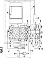
- the lubricant flows from the lubricant filter 60 in a lubricant delivery line 62 to a branch 64, via which a first lubricant supply system 70, in Fig. 2 shown in solid lines, the lubricant leads to supply openings 72 and 74, which are assigned to the rotor bores 32 and 34 and supply the screw rotors 36 and 38 in areas 76 and 78 of lubricant, which lie between suction sides 82 and 84 and high-pressure sides 86 and 88 thereof.
- the first lubricant supply system 70 also comprises lubricant outlets 92 and 94 for lubricating the bearings 46 and 48 on the high-pressure side, the lubricant flowing through the bearings 46 and 48 on the high-pressure side being collected again and fed via a collecting line 96 to an additional feed opening 98, which is assigned to the first screw rotor 32, for example , wherein the feed opening 98 lies between the feed opening 72 and the suction side 82 of the screw rotor 32.
- Lubricant supply system 100 shown in dotted lines is provided, both the first lubricant supply system 70 and the second lubricant supply system 100 starting from a branch 102 connected to the branch 64 and thus fed by the lubricant delivery line 62.
- the second lubricant supply system 100 leads lubricant to a feed opening 104, which is assigned to the screw rotor 34, for example, but it is also entirely possible to provide a feed opening in the second lubricant feed system 100 which is assigned to the first screw runner 32.
- the second lubricant supply system 100 there is a control valve, designated as a whole by 110, which can be controlled by a compressor control 120 and with which the second lubricant supply system 100 can be operated controlled by the compressor control 120.
- an activatable and deactivatable lubricant cooling device 130 which comprises a lubricant cooler 136, which is connected through a bypass line 132 with a control valve 134 provided in the bypass line 132 is operable in the active state or in the inactive state or in intermediate states between them.
- a third lubricant supply system 140 leads from the branch 64 to the low-pressure-side bearings 42 and 44 in order to supply them with lubricant.
- the third lubricant supply system 140 can also branch off from the branch 102, so that lubricant, which can at least be cooled, also flows through it.
- the housing 10 is preferably designed such that it has a lubricant outlet 152 connected to the branch 64 and a lubricant inlet 154 for the first lubricant supply system 70 and a lubricant inlet 156 for the second lubricant supply system 100.
- a distributor unit Connected to the lubricant outlet 152 and the lubricant inlets 154 and 156 is a distributor unit, designated as a whole by 160, in which external connections 162 and 164 for connecting the external lubricant cooler 136 and the bypass line 132 to the control valve 134 are provided, and in which the branch 102 is also provided With a feed line 166 to the lubricant inlet 154 of the first lubricant supply system and a feed line 168 to the lubricant inlet 156 of the second lubricant supply system 100 are provided, the control valve 110 also being arranged in the feed line 168.
- the distributor unit 160 is preferably mounted on the housing 10 as an external unit and adjoins the lubricant outlet 152 and the lubricant inlets 154 and 156 in order to establish a connection to the bypass line 132 and the feed lines 166 and 168.
- the screw compressor according to the illustrated embodiment now works as follows.
- the second lubricant supply system 100 is inactive because the compressor control 120 closes the control valve 110.
- the screw rotors 36, 38 and the bearings 42, 44, 46, 48 are supplied with lubricant only via the first lubricant supply system 70 and the third lubricant supply system 140, which is then collected again in the lubricant sump 58 and made available for renewed lubrication.
- the amount of lubricant that is used in normal load operation depends on how large the pressure difference between the high-pressure lubricant sump 58 and essentially the supply openings 72 and 74 and 98 is, since this pressure difference essentially promotes the lubricant.
- the compressor controller 120 can also open the control valve 134, so that the lubricant cooler 136 does not have a significant amount of flow through the circulating lubricant.
- control valve 134 there is also the possibility of closing the control valve 134 or operating it in a clocked or modulated manner in order to let either all of the circulating lubricant flow through the lubricant cooler 136 or a part thereof through the lubricant cooler 136 and thus heat from the housing by cooling the lubricant 10 dissipate.
- the screw compressor according to the invention works in a high-load operation, that is to say under high load, it is necessary to dissipate as much heat as possible from the housing 10 via the lubricant in order to stabilize the temperature. For this reason, the control valve 134 is closed in the high-load operation, so that the bypass line 132 is blocked and the entire lubricant flowing to the branch 102 flows through the lubricant cooler 136.
- the circulating amount of lubricant is considerably increased, in particular since the supply opening 104 is closer to the suction sides 82 and 84 of the screw rotors 32 and 34 than the supply openings 72 and 74, so that a higher pressure difference that promotes the lubricant is available in the second lubricant supply system 100.
- the amount of lubricant flowing through the second lubricant supply system 100 in high-load operation is preferably more than 0.5 times the amount of lubricant flowing through the first lubricant supply system 70, preferably this amount of lubricant can extend approximately to the extent of the amount of lubricant flowing through the first lubricant supply system 70 so that as a result of the high amounts of lubricant flowing through the lubricant cooler 136, efficient cooling of the screw compressor according to the invention is possible.
- the compressor control 120 can detect the high-load operation in a wide variety of ways. For example, it is conceivable to detect the high-load operation on the basis of the electrical power consumed by the drive motor 20 and / or there is the possibility of providing a high-pressure temperature sensor 170 or a lubricant temperature sensor, for example arranged in the lubricant sump 58, by means of which an overwriting of a temperature threshold can be determined , which is an indication of high-load operation.
- control valve 134 being open in uncooled normal load operation, for example with very little load on the screw compressor, while in cooled normal load operation , for example when the screw compressor is subjected to a greater load, the control valve 134 is closed and the lubricant therefore flows through the lubricant cooler 136 in the cooled normal load operation, the cooling capacity obtainable here being considerably lower than in the high load operation described above due to the smaller amount of lubricant in the normal load operation.
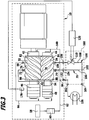
- FIG. 3 The illustrated simplified embodiment of a compressor according to the invention eliminates the detour line 132 and the control valve 134, so that the lubricant flowing to the branch 102 always flows through the lubricant cooler 136 and is cooled therein.
- the high-load operation by switching on the second lubricant supply system 100 leads to a significant increase in the amount of lubricant cooled by the lubricant cooler 136, so that, according to the invention, the cooling of the screw compressor in high-load operation is improved compared to normal load operation.
Landscapes
- Engineering & Computer Science (AREA)
- Mechanical Engineering (AREA)
- General Engineering & Computer Science (AREA)
- Applications Or Details Of Rotary Compressors (AREA)
Description
- Die Erfindung betrifft einen Schraubenverdichter umfassend ein Gehäuse, mindestens einen in einem Verdichtergehäuse des Gehäuses angeordneten Schraubenläufer, einen hochdruckseitig angeordneten Schmiermittelsumpf, in welchem sich Schmiermittel sammelt, und eine Schmiermittelzufuhreinrichtung, welche aus dem Schmiermittelsumpf Schmiermittel dem mindestens einen Schraubenläufer zuführt.
- Derartige Schraubenverdichter sind aus dem Stand der Technik bekannt, bei diesen ist eine ständig betriebene Schmiermittelzufuhreinrichtung vorgesehen, die so auszulegen ist, dass das in dieser umgewälzte Schmiermittel auch bei maximaler Belastung eine ausreichende Wärmeabfuhr aus dem Gehäuse des Schraubenverdichters sicherstellt, so dass ständig eine große Menge von Schmiermittel umläuft.
- Hierzu ist beispielsweise noch eine Schmiermittelkühleinrichtung vorgesehen, welche das umlaufende Schmiermittel kühlt.
- Die
WO 2009/121151 A1 , die als nächstliegender Stand der Technik angesehen wird, offenbart einen Schraubenverdichter umfassend ein Gehäuse, mindestens einen in einem Verdichtergehäuse des Gehäuses angeordneten Schraubenläufer, einen hochdruckseitig angeordneten Schmiermittelsumpf, in welchem sich Schmiermittel sammelt, und eine Schmiermittelzufuhreinrichtung, welche aus dem Schmiermittelsumpf Schmiermittel dem mindestens einen Schraubenläufer zuführt, und welche ein erstes Schmiermittelzufuhrsystem und ein zweites Schmiermittelzufuhrsystem umfasst, wobei das erste Schmiermittelzufuhrsystem beim Betrieb des Schraubenverdichters Schmiermittel dem mindestens einen Schraubenläufer zuführt, dass das zweite Schmiermittelzufuhrsystem zusätzlich dem mindestens einen Schraubenläufer Schmiermittel zuführt, und wobei mittels der beiden Schmiermittelzufuhrsysteme über Einspritzventile dem mindestens einen Schraubenläufer Öl zugeführt wird, um die Temperatur hochdruckseitig selbst bei hohen Umgebungstemperaturen und/oder hohen Verdichterdrehzahlen und/oder hohen Verdichtungsdrucken niedrig zu halten, wobei durch mindestens eine Temperaturmessung, insbesondere der Temperatur des verdichteten Mediums, das den Verdichter verlässt, und die Umgebungstemperatur die Menge des Öls, die durch das Einspritzventil des zweiten Schmiermittelzufuhrsystems eingespritzt wird, eingestellt wird.. - Der Erfindung liegt die Aufgabe zugrunde, einen Schraubenverdichter der vorstehend beschriebenen Art dahingehend zu verbessern, dass bei ausreichender Schmierung die Menge des umlaufenden Schmiermittels möglichst gering gehalten werden kann.
- Diese Aufgabe wird bei einem Schraubenverdichter der eingangs beschriebenen Art erfindungsgemäß durch die Merkmale des Anspruchs 1 gelöst.
- Der Vorteil der erfindungsgemäßen Lösung ist darin zu sehen, dass das aktivierbare und deaktivierbare zweite Schmiermittelzufuhrsystem die Möglichkeit eröffnet, die umlaufende Schmiermittelmenge an den Betriebszustand des Schraubenverdichters anzupassen und damit die Schmiermittelmenge an den jeweils vorliegenden Betriebszustand möglichst optimal anzupassen.
- Besonders günstig ist es dabei, wenn der Schraubenverdichter in einem Normallastbetrieb und in einem Hochlastbetrieb betreibbar ist und wenn im Normallastbetrieb das zweite Schmiermittelzufuhrsystem deaktiviert und bei Hochlastbetrieb aktiviert ist.
- Der Vorteil dieser Lösung ist darin zu sehen, dass damit die Möglichkeit besteht, durch das zweite Schmiermittelzufuhrsystem die umlaufende Schmiermittelmenge im Hochlastbetrieb zu steigern und damit für eine ausreichende Kühlung des Schraubenverdichters im Hochlastbetrieb zu sorgen, jedoch für den Normallastbetrieb die umlaufende Schmiermittelmenge in Bezug auf den Hochlastbetrieb zu verringern.
- Prinzipiell wäre es denkbar, den Normallastbetrieb und den Hochlastbetrieb je nach Betriebsvorgaben für den Schraubenverdichter zu definieren.
- Eine besonders günstige Lösung sieht jedoch eine Verdichtersteuerung vor, welche erkennt, ob ein Normallastbetrieb oder ein Hochlastbetrieb vorliegt.
- Eine derartige Differenzierung zwischen einem Normallastbetrieb und einem Hochlastbetrieb kann in unterschiedlichster Art und Weise erfolgen.
- Beispielsweise ist vorgesehen, dass unterhalb eines vorgebbaren Schwellwerts für die Belastung des Schraubenverdichters der Normallastbetrieb und oberhalb des Schwellwerts für die Belastung der Hochlastbetrieb vorliegt, so dass insbesondere die Verdichtersteuerung in der Lage ist, anhand des vorgebbaren Schwellwerts zwischen dem Normallastbetrieb und dem Hochlastbetrieb zu unterscheiden.
- Ein derartiger Schwellwert für die Belastung des Schraubenverdichters könnte beispielsweise die aufgenommene Leistung eines Antriebs für den Schraubenverdichter sein.
- Alternativ oder ergänzend sieht eine vorteilhafte Lösung vor, dass dann, wenn eine hochdruckseitig gemessene Temperatur unterhalb einer vorgebbaren Temperaturschwelle liegt, der Normallastbetrieb und dann, wenn die gemessene Temperatur oberhalb der Temperaturschwelle liegt, der Hochlastbetrieb ausgeführt wird.
- Hinsichtlich der durch das erste Schmiermittelzufuhrsystem strömenden Schmiermittelmenge und der Festlegung derselben wurden bislang keine näheren Angaben gemacht.
- So wäre es beispielsweise denkbar, eine Schmiermittelförderpumpe vorzusehen, durch welche die Schmiermittelmenge, die durch das erste Schmiermittelzufuhrsystem strömt, festlegbar ist, wobei die Schmiermittelmenge entsprechend der Drehzahl des Schraubenläufers variieren kann.
- Eine besonders vorteilhafte Ausführungsform eines erfindungsgemäßen Schraubenverdichters sieht jedoch vor, dass die durch das erste Schmiermittelzufuhrsystem strömende Schmiermittelmenge durch eine Druckdifferenz zwischen einem Druck im Schmiermittelsumpf und einem Druck an einer Zufuhröffnung zum mindestens einen Schraubenläufer festgelegt ist.
- Eine derartige Lösung hat den großen Vorteil, dass einerseits eine Schmiermittelförderpumpe entfallen kann und andererseits in einfacher Weise die Schmiermittelmenge, die zur Schmierung erforderlich ist, festlegbar ist.
- Darüber hinaus ist vorteilhafterweise auch im Zusammenhang mit dem zweiten Schmiermittelzufuhrsystem vorgesehen, dass die durch das zweite Schmiermittelzufuhrsystem strömende Schmiermittelmenge durch eine Druckdifferenz zwischen einem Druck im Schmiermittelsumpf und einem Druck an einer Zufuhröffnung zum mindestens einen Schraubenläufer festgelegt ist.
- Damit lässt sich auch in einfacher Weise die Schmiermittelmenge durch das zweite Schmiermittelzufuhrsystem festlegen.
- Insbesondere besteht auch die Möglichkeit, die durch das zweite Schmiermittelzufuhrsystem strömende Schmiermittelmenge dadurch festzulegen, dass die Zufuhröffnung auf einem anderen Druck liegt als die Zufuhröffnung des ersten Schmiermittelzufuhrsystems.
- Der Druck an den jeweiligen Zufuhröffnungen ergibt sich primär daraus, an welcher Stelle des jeweiligen Schraubenläufers die Zufuhröffnung zur Zufuhr von Schmiermittel zu diesem vorgesehen ist, also daraus, an welcher Stelle zwischen der Hochdruckseite und der Saugseite des Schraubenläufers die jeweilige Zufuhröffnung liegt.
- Im Zusammenhang mit der bisherigen Beschreibung der einzelnen Ausführungsformen wurde nicht näher darauf eingegangen, ob eine gezielte Kühlung der Schmiermittelmengen erfolgen soll.
- So sieht eine vorteilhafte Lösung vor, dass die von dem ersten Schmiermittelzufuhrsystem geführte Schmiermittelmenge durch eine Schmiermittelkühleinrichtung kühlbar ist, so dass durch diese Schmiermittelkühleinrichtung in definierter Weise Wärme aus der im ersten Schmiermittelzufuhrsystem umlaufenden Schmiermittelmenge abgeführt werden kann.
- Eine einfache Lösung sieht dabei vor, dass die Schmiermittelkühleinrichtung die von dem ersten Schmiermittelzufuhrsystem geführte Schmiermittelmenge ständig kühlt.
- Alternativ dazu ist es aber auch denkbar, dass die Schmiermittelkühleinrichtung die von dem ersten Schmiermittelzufuhrsystem geführte Schmiermittelmenge im Hochlastbetrieb des Verdichters kühlt.
- Eine weitere Variante ist noch die, dass die Schmiermittelkühleinrichtung gesteuert im Normallastbetrieb gegebenenfalls die durch das erste Schmiermittelzufuhrsystem strömende Schmiermittelmenge kühlt.
- Eine weitere vorteilhafte Lösung sieht vor, dass die von dem zweiten Schmiermittelzufuhrsystem geführte Schmiermittelmenge durch eine Schmiermittelkühleinrichtung kühlbar ist.
- Diese Schmiermittelkühleinrichtung kann identisch sein mit der Kühleinrichtung für die Schmiermittelmenge des ersten Schmiermittelzufuhrsystems.
- Es ist aber auch denkbar, für die Schmiermittelmenge des zweiten Schmiermittelzufuhrsystems eine separate Schmiermittelkühleinrichtung vorzusehen.
- Eine besonders günstige Lösung sieht vor, dass mit der Schmiermittelkühleinrichtung die Schmiermittelmengen des ersten und zweiten Schmiermittelzufuhrsystems kühlbar sind.
- Im Rahmen der erfindungsgemäßen Lösung hat es sich als besonders vorteilhaft erwiesen, wenn eine Schmiermittelkühleinrichtung vorgesehen ist, die in einem aktiven Zustand oder in einem inaktiven Zustand und/oder in Zuständen zwischen diesen betreibbar ist.
- Beispielsweise ist eine derartige Schmiermittelkühleinrichtung so ausgebildet, dass diese einen Schmiermittelkühler aufweist, der durch eine steuerbare Umgehungsleitung in allen möglichen Zuständen von aktiven bis zum inaktiven Zustand betreibbar ist.
- Zur Ausführung des erfindungsgemäßen Schraubenverdichters wurden im Einzelnen keine näheren Angaben gemacht.
- So sieht eine besonders vorteilhafte Lösung vor, dass an dem Gehäuse ein Schmiermittelausgang zur Zufuhr von Schmiermittel zu den Schmiermittelzufuhrsystemen sowie Schmiermitteleingänge zur Zufuhr von Schmiermittel zum ersten Schmiermittelzufuhrsystem und zum zweiten Schmiermittelzufuhrsystem vorgesehen sind.
- Damit lassen sich in einfacher Weise die Schmiermittelzufuhrsysteme separat aktivieren und gegebenenfalls die Aktivierung steuern, ohne dass hierzu Eingriffe in das Gehäuse erforderlich sind.
- Besonders günstig ist es dabei, wenn der Schmiermittelausgang und die Schmiermitteleingänge in eine Verteilereinheit münden, welche an dem Gehäuse montierbar ist.
- Damit lässt sich durch eine extern des Gehäuses vorgesehene Verteilereinheit in einfacher Weise die Verteilung des Schmiermittels auf die Schmiermittelzufuhrsysteme sowie die Aktivierung insbesondere des zweiten Schmiermittelzufuhrsystems realisieren.
- Ferner lässt sich die Verteilereinheit vorzugsweise so aufbauen, dass diese Anschlüsse für einen externen Schmiermittelkühler aufweist, so dass auch der Anschluss des externen Schmiermittelkühlers über die Verteilereinheit erfolgt.
- Ferner lässt sich die Verteilereinheit vorzugsweise so ausführen, dass in der Verteilereinheit vom Schmiermittelkühler zurückgeführtes Schmiermittel dem ersten Schmiermittelzufuhrsystem und dem zweiten Schmiermittelzufuhrsystem zuführbar ist.
- Ferner ist vorzugsweise vorgesehen, dass in der Verteilereinheit vor dem Schmiermitteleingang des zweiten Schmiermittelzufuhrsystems ein Steuerventil vorgesehen ist.
- Außerdem ist vorzugsweise noch vorgesehen, dass in der Verteilereinheit eine zwischen den Anschlüssen für den externen Schmiermittelkühler liegende Umgehungsleitung mit einem Steuerventil vorgesehen ist, welche die Möglichkeit eröffnet, den Schmiermittelkühler zu aktivieren oder zu deaktivieren oder auch Zwischenzustände einzustellen.
- Weitere Merkmale und Vorteile der Erfindung sind Gegenstand der nachfolgenden Beschreibung sowie der zeichnerischen Darstellung einiger Ausführungsbeispiele.
- In der Zeichnung zeigen:
- Fig. 1
- einen Längsschnitt durch ein erstes Ausführungsbeispiel eines erfindungsgemäßen Schraubenverdichters;
- Fig. 2
- eine schematische Darstellung eines erfindungsgemäßen Schraubenverdichters mit einer Schmiermittelzufuhreinrichtung gemäß dem ersten Ausführungsbeispiel und
- Fig. 3
- eine Darstellung ähnlich
Fig. 2 einer Schmiermittelzufuhreinrichtung bei einem zweiten Ausführungsbeispiel eines erfindungsgemäßen Schraubenverdichters. - Ein in
Fig. 1 dargestelltes Ausführungsbeispiel eines erfindungsgemäßen Schraubenverdichters, umfasst ein als Ganzes mit 10 bezeichnetes Gehäuse, welches aus einem Mittelabschnitt 12, einem motorseitigen Endabschnitt 14 und einem druckseitigen Endabschnitt 16 aufgebaut ist. - In dem motorseitigen Endabschnitt 14 ist ein als Ganzes mit 20 bezeichneter Antriebsmotor angeordnet, welcher beispielsweise als Elektromotor ausgebildet ist, der einen in dem Endabschnitt 14 gehaltenen Stator 22 umfasst, welcher einen Rotor 24 umschließt, der seinerseits auf einer Antriebswelle 26 angeordnet ist.
- In dem Mittelabschnitt 12 des Außengehäuses 10 ist ein als Ganzes mit 30 bezeichnetes Verdichtergehäuse ausgebildet, welches Läuferbohrungen 32 und 34 aufweist, in welchen Schraubenläufer 36 und 38 angeordnet sind, die um zueinander parallele Achsen drehbar sind.
- Beispielsweise sitzt der Schraubenläufer 36 auf der diesen durchsetzenden Antriebswelle 26.
- Zur Lagerung der Schraubenläufer 36 und 38 sind niederdruckseitige Lager 42 und 44 sowie hochdruckseitige Lager 46 und 48 vorgesehen, die in entsprechenden Lageraufnahmen des Gehäuses 10 angeordnet sind.
- Die Schraubenläufer 36 und 38 verdichten dabei über einen Saugraum 50 zugeführtes Medium, welches über einen Hochdruckauslass 52 ausströmt und dabei beispielsweise einen Schalldämpfer 54 sowie einen Schmiermittelabscheider 56 durchsetzt, welcher bewirkt, dass aus dem verdichteten Medium Schmiermittel ausgeschieden wird, welches sich in dem druckseitigen Endabschnitt 16 in Form eines Schmiermittelsumpfes 58 sammelt.
- Alternativ dazu können der Schmiermittelabscheider und der Schmiermittelsumpf auch außerhalb des Gehäuses 10 angeordnet sein, wobei diese stets hochdruckseitig liegen.
- Aus dem Schmiermittelsumpf 58 wird das Schmiermittel über einen Schmiermittelfilter 60 aufgenommen und steht zur Schmierung der niederdruckseitigen Lager 42 und 44 sowie der hochdruckseitigen Lager 46 und 48 und der Schraubenläufer 36 und 38 in den Läuferbohrungen 32 und 34 zur Verfügung.
- Wie in
Fig. 2 schematisch dargestellt, strömt das Schmiermittel von dem Schmiermittelfilter 60 in einer Schmiermittelförderleitung 62 zu einer Verzweigung 64, über welche ein erstes Schmiermittelzufuhrsystem 70, inFig. 2 durchgezogen dargestellt, das Schmiermittel zu Zufuhröffnungen 72 und 74 führt, die den Läuferbohrungen 32 und 34 zugeordnet sind und den Schraubenläufern 36 und 38 in Bereichen 76 und 78 Schmiermittel zuführen, die zwischen Saugseiten 82 und 84 sowie Hochdruckseiten 86 und 88 derselben liegen. - Ferner umfasst das erste Schmiermittelzufuhrsystem 70 noch Schmiermittelauslässe 92 und 94 zur Schmierung der hochdruckseitigen Lager 46 und 48, wobei beispielsweise das die hochdruckseitigen Lager 46 und 48 durchströmende Schmiermittel wieder gesammelt wird und über eine Sammelleitung 96 einer beispielsweise dem ersten Schraubenläufer 32 zugeordneten zusätzlichen Zufuhröffnung 98 zugeführt wird, wobei die Zufuhröffnung 98 zwischen der Zufuhröffnung 72 und der Saugseite 82 des Schraubenläufers 32 liegt.
- Parallel zum ersten Schmiermittelzufuhrsystem 70 ist ein zweites, in
Fig. 2 punktiert dargestelltes, Schmiermittelzufuhrsystem 100 vorgesehen, wobei sowohl das erste Schmiermittelzufuhrsystem 70 und das zweite Schmiermittelzufuhrsystem 100 von einer mit der Verzweigung 64 verbundenen und somit von der Schmiermittelförderleitung 62 gespeisten Verzweigung 102 ausgehen. Das zweite Schmiermittelzufuhrsystem 100 führt Schmiermittel zu einer beispielsweise dem Schraubenläufer 34 zugeordneten Zufuhröffnung 104, es ist aber durchaus möglich, auch eine dem ersten Schraubenläufer 32 zugeordnete Zufuhröffnung in dem zweiten Schmiermittelzufuhrsystem 100 vorzusehen. - Ferner ist in dem zweiten Schmiermittelzufuhrsystem 100 ein als Ganzes mit 110 bezeichnetes Steuerventil vorgesehen, welches durch eine Verdichtersteuerung 120 steuerbar ist und mit welchem das zweite Schmiermittelzufuhrsystem 100 durch die Verdichtersteuerung 120 gesteuert betreibbar ist.
- Zwischen der Verzweigung 64 und der Verzweigung 102, von welcher das erste Schmiermittelzufuhrsystem 70 und das zweite Schmiermittelzufuhrsystem 100 ausgehen, liegt eine aktivierbare und deaktivierbare Schmiermittelkühleinrichtung 130, welche einen Schmiermittelkühler 136 umfasst, der durch eine Umgehungsleitung 132 mit einem in der Umgehungsleitung 132 vorgesehenen Steuerventil 134 im aktiven Zustand oder im inaktiven Zustand oder in Zwischenzuständen zwischen diesen betreibbar ist.
- Ferner führt von der Verzweigung 64 noch ein drittes Schmiermittelzufuhrsystem 140 zu den niederdruckseitigen Lagern 42 und 44, um diese mit Schmiermittel zu versorgen.
- Alternativ dazu kann das dritte Schmiermittelzufuhrsystem 140 auch von der Verzweigung 102 abzweigen, so dass durch dieses ebenfalls zumindest kühlbares Schmiermittel strömt.
- Vorzugsweise ist das Gehäuse 10 so ausgebildet, dass es einen mit der Verzweigung 64 verbundenen Schmiermittelausgang 152 sowie einen Schmiermitteleingang 154 für das erste Schmiermittelzufuhrsystem 70 sowie einen Schmiermitteleingang 156 für das zweite Schmiermittelzufuhrsystem 100 aufweist.
- Mit dem Schmiermittelausgang 152 und den Schmiermitteleingängen 154 und 156 ist eine als Ganzes mit 160 bezeichnete Verteilereinheit verbunden, in welcher externe Anschlüsse 162 und 164 zum Anschluss des externen Schmiermittelkühlers 136 sowie die Umgehungsleitung 132 mit dem Steuerventil 134 vorgesehen sind und in welcher außerdem die Verzweigung 102 mit einer Zuleitung 166 zum Schmiermitteleingang 154 des ersten Schmiermittelzufuhrsystems und mit einer Zuleitung 168 zum Schmiermitteleingang 156 des zweiten Schmiermittelzufuhrsystems 100 vorgesehen sind, wobei in der Zuleitung 168 auch noch das Steuerventil 110 angeordnet ist.
- Die Verteilereinheit 160 ist vorzugsweise als externe Einheit an dem Gehäuse 10 montiert und grenzt an den Schmiermittelausgang 152 sowie die Schmiermitteleingänge 154 und 156, um eine Verbindung zu der Umwegleitung 132 sowie den Zuleitungen 166 und 168 herzustellen.
- Der Schraubenverdichter gemäß dem dargestellten Ausführungsbeispiel arbeitet nun wie folgt.
- In einem Normallastbetrieb, das heißt einer Belastung des Schraubenverdichters gemäß üblichen Betriebszyklen, ist das zweite Schmiermittelzufuhrsystem 100 inaktiv, da die Verdichtersteuerung 120 das Steuerventil 110 schließt.
- In diesem Fall wird den Schraubenläufern 36, 38 und den Lagern 42, 44, 46, 48 lediglich über das erste Schmiermittelzufuhrsystem 70 sowie das dritte Schmiermittelzufuhrsystem 140 Schmiermittel zugeführt, das dann wieder im Schmiermittelsumpf 58 gesammelt und zur erneuten Schmierung zur Verfügung gestellt wird.
- Die Schmiermittelmenge, die im Normallastbetrieb eingesetzt wird, hängt dabei davon ab, wie groß die Druckdifferenz zwischen dem unter Hochdruck stehenden Schmiermittelsumpf 58 und im Wesentlichen den Zufuhröffnungen 72 und 74 sowie 98 ist, da durch diese Druckdifferenz eine Förderung des Schmiermittels im Wesentlichen erfolgt.
- Im Normallastbetrieb kann die Verdichtersteuerung 120 auch das Steuerventil 134 öffnen, so dass der Schmiermittelkühler 136 nicht in nennenswertem Maße vom umlaufenden Schmiermittel durchströmt ist.
- Es besteht aber auch die Möglichkeit, das Steuerventil 134 zu schließen oder getaktet oder moduliert zu betreiben, um entweder das ganze umlaufende Schmiermittel durch den Schmiermittelkühler 136 oder einen Teil desselben durch den Schmiermittelkühler 136 durchströmen zu lassen und somit durch Kühlung des Schmiermittels Wärme aus dem Gehäuse 10 abzuführen.
- Arbeitet jedoch der erfindungsgemäße Schraubenverdichter in einem Hochlastbetrieb, das heißt bei hoher Belastung, ist es erforderlich, zur Stabilisierung der Temperatur über das Schmiermittel eine möglichst große Wärmemenge aus dem Gehäuse 10 abzuführen. Aus diesem Grund wird im Hochlastbetrieb das Steuerventil 134 geschlossen, so dass die Umgehungsleitung 132 gesperrt ist und das zur Verzweigung 102 strömende gesamte Schmiermittel durch den Schmiermittelkühler 136 strömt.
- Ferner wird durch Aktivieren des zweiten Schmiermittelzufuhrsystems 100 aufgrund eines Öffnens des Steuerventils 110 durch die Verdichtersteuerung 120 die umlaufende Schmiermittelmenge erheblich vergrößert, insbesondere da die Zufuhröffnung 104 näher an den Saugseiten 82 und 84 der Schraubenläufer 32 und 34 liegt als die Zufuhröffnungen 72 und 74, so dass eine höhere das Schmiermittel fördernde Druckdifferenz im zweiten Schmiermittelzufuhrsystem 100 zur Verfügung steht. Die durch das zweite Schmiermittelzufuhrsystem 100 im Hochlastbetrieb strömende Schmiermittelmenge beträgt vorzugsweise mehr als das 0,5-fache der durch das erste Schmiermittelzufuhrsystem 70 strömenden Schmiermittelmenge, vorzugsweise kann diese Schmiermittelmenge näherungsweise bis zu dem Umfang der durch das erste Schmiermittelzufuhrsystem 70 strömenden Schmiermittelmenge reichen, so dass dadurch durch die hohen, den Schmiermittelkühler 136 durchströmenden Schmiermittelmengen eine effiziente Kühlung des erfindungsgemäßen Schraubenverdichters möglich ist.
- Die Verdichtersteuerung 120 kann dabei den Hochlastbetrieb in unterschiedlichster Art und Weise erfassen. So ist es beispielsweise denkbar, den Hochlastbetrieb aufgrund der vom Antriebsmotor 20 aufgenommenen elektrischen Leistung zu erfassen und/oder es besteht die Möglichkeit, einen hochdruckseitigen Temperatursensor 170 oder einen Schmiermitteltemperatursensor, beispielsweise im Schmiermittelsumpf 58 angeordnet, vorzusehen, mittels welchem ein Überschreiben einer Temperaturschwelle feststellbar ist, welche ein Indiz für einen Hochlastbetrieb darstellt.
- Alternativ zu der vorstehend beschriebenen Betriebsweise des erfindungsgemäßen Schraubenverdichters besteht auch die Möglichkeit, im Normallastbetrieb, zwischen einem ungekühltem und einem gekühlten Normallastbetrieb zu differenzieren, wobei im ungekühlten Normallastbetrieb, beispielsweise bei ganz geringer Belastung des Schraubenverdichters, das Steuerventil 134 geöffnet ist, während im gekühlten Normallastbetrieb, beispielsweise bei stärkerer Belastung des Schraubenverdichters, das Steuerventil 134 geschlossen ist und somit das Schmiermittel in dem gekühlten Normallastbetrieb den Schmiermittelkühler 136 durchströmt, wobei die hierbei erhältliche Kühlleistung aufgrund der geringeren Schmiermittelmenge im Normallastbetrieb erheblich geringer ist als im vorstehend beschriebenen Hochlastbetrieb.
- Bei einem zweiten, in
Fig. 3 dargestellten vereinfachten Ausführungsbeispiel eines erfindungsgemäßen Verdichters entfallen die Umwegleitung 132 sowie das Steuerventil 134, so dass das zur Verzweigung 102 strömende Schmiermittel stets den Schmiermittelkühler 136 durchströmt und in diesem gekühlt wird. - Der Hochlastbetrieb durch Zuschalten des zweiten Schmiermittelzufuhrsystems 100 führt zu einer signifikanten Erhöhung der von dem Schmiermittelkühler 136 gekühlten Schmiermittelmenge, so dass dadurch erfindungsgemäß die Kühlung des Schraubenverdichters im Hochlastbetrieb gegenüber dem Normallastbetrieb verbessert wird.
Claims (15)
- Schraubenverdichter umfassend ein Gehäuse (10), mindestens einen in einem Verdichtergehäuse (30) des Gehäuses (10) angeordneten Schraubenläufer (36, 38), einen hochdruckseitig angeordneten Schmiermittelsumpf (58), in welchem sich Schmiermittel sammelt, und eine Schmiermittelzufuhreinrichtung (70, 100, 140), welche aus dem Schmiermittelsumpf (58) Schmiermittel dem mindestens einen Schraubenläufer (36, 38) zuführt, und welche ein erstes Schmiermittelzufuhrsystem (70) und ein zweites Schmiermittelzufuhrsystem (100) umfasst, wobei das erste Schmiermittelzufuhrsystem (70) beim Betrieb des Schraubenverdichters Schmiermittel dem mindestens einen Schraubenläufer (36, 38) zuführt, und das zweite Schmiermittelzufuhrsystem (100) zusätzlich dem mindestens einen Schraubenläufer (36, 38) Schmiermittel zuführt, und dabei aktivierbar und deaktivierbar ist, wobei der Schraubenverdichter in einem Normallastbetrieb und in einem Hochlastbetrieb betreibbar ist, wobei eine Zufuhröffnung (104) des zweiten Schmiermittelzufuhrsystems (100) näher an einer Saugseite (82, 84) des mindestens einen Schraubenläufers (36, 38) liegt, als eine Zufuhröffnung (72, 74) des ersten Schmiermittelzufuhrsystems (70), und wobei im Normallastbetrieb das zweite Schmiermittelzufuhrsystem (100) deaktiviert und bei Hochlastbetrieb aktiviert ist und dass eine Verdichtersteuerung (120) vorgesehen ist, welche erkennt, ob ein Normallastbetrieb oder ein Hochlastbetrieb vorliegt.
- Schraubenverdichter nach Anspruch 1, dadurch gekennzeichnet, dass unterhalb eines vorgebbaren Schwellwerts für die Belastung des Schraubenverdichters der Normallastbetrieb und oberhalb des Schwellwerts für die Belastung der Hochlastbetrieb vorliegt.
- Schraubenverdichter nach einem der voranstehenden Ansprüche, dadurch gekennzeichnet, dass dann, wenn eine hochdruckseitig gemessene Temperatur unterhalb einer vorgebbaren Temperaturschwelle liegt, der Normallastbetrieb und dann, wenn die gemessene Temperatur oberhalb der Temperaturschwelle liegt, der Hochlastbetrieb ausgeführt wird.
- Schraubenverdichter nach einem der voranstehenden Ansprüche, dadurch gekennzeichnet, dass die durch das erste Schmiermittelzufuhrsystem (70) strömende Schmiermittelmenge durch eine Druckdifferenz zwischen einem Druck im Schmiermittelsumpf (58) und einem Druck an einer Zufuhröffnung (72, 74, 98) zu dem mindestens einen Schraubenläufer (36, 38) festgelegt ist.
- Schraubenverdichter nach einem der voranstehenden Ansprüche, dadurch gekennzeichnet, dass die durch das zweite Schmiermittelzufuhrsystem (100) strömende Schmiermittelmenge durch eine Druckdifferenz zwischen einem Druck im Schmiermittelsumpf (58) und einem Druck an einer Zufuhröffnung (104) zu dem mindestens einen Schraubenläufer (36, 38) festgelegt ist.
- Schraubenverdichter nach einem der voranstehenden Ansprüche, dadurch gekennzeichnet, dass die von dem ersten Schmiermittelzufuhrsystem (70) geführte Schmiermittelmenge durch eine Schmiermittelkühleinrichtung (130) kühlbar ist.
- Schraubenverdichter nach Anspruch 6, dadurch gekennzeichnet, dass die Schmiermittelkühleinrichtung (130) die von dem ersten Schmiermittelzufuhrsystems (70) geführte Schmiermittelmenge ständig kühlt.
- Schraubenverdichter nach Anspruch 7, dadurch gekennzeichnet, dass die Schmiermittelkühleinrichtung (130) die von dem ersten Schmiermittelzufuhrsystem (70) geführte Schmiermittelmenge im Hochlastbetrieb des Schraubenverdichters kühlt.
- Schraubenverdichter nach einem der voranstehenden Ansprüche, dadurch gekennzeichnet, dass die von dem zweiten Schmiermittelzufuhrsystem (100) geführte Schmiermittelmenge durch eine Schmiermittelkühleinrichtung (130) kühlbar ist und dass insbesondere mit der Schmiermittelkühleinrichtung (130) die Schmiermittelmengen des ersten und zweiten Schmiermittelzufuhrsystems (70, 100) kühlbar sind.
- Schraubenverdichter nach einem der voranstehenden Ansprüche, dadurch gekennzeichnet, dass eine Schmiermittelkühleinrichtung (130) vorgesehen ist, die in einem aktiven Zustand oder einem inaktiven Zustand und/oder in Zuständen zwischen diesen betreibbar ist.
- Schraubenverdichter nach Anspruch 10, dadurch gekennzeichnet, dass die Schmiermittelkühleinrichtung (130) einen Schmiermittelkühler (136) aufweist, der durch eine steuerbare Umgehungsleitung (132) in allen möglichen Zuständen vom aktiven Zustand bis inaktiven Zustand betreibbar ist.
- Schraubenverdichter nach einem der voranstehenden Ansprüche, dadurch gekennzeichnet, dass an dem Gehäuse (10) ein Schmiermittelausgang (152) zur Zufuhr von Schmiermittel zu den Schmiermittelzufuhrsystemen (70, 100) sowie Schmiermitteleingänge (154, 156) zur Zufuhr von Schmiermittel zum ersten Schmiermittelzufuhrsystem (70) und zum zweiten Schmiermittelzufuhrsystem (100) vorgesehen sind.
- Schraubenverdichter nach Anspruch 12, dadurch gekennzeichnet, dass der Schmiermittelausgang (152) und die Schmiermitteleingänge (154, 156) in eine Verteilereinheit (160) münden, welche an dem Gehäuse (10) montierbar ist.
- Schraubenverdichter nach Anspruch 13, dadurch gekennzeichnet, dass die Verteilereinheit (160) Anschlüsse (162, 164) für einen externen Schmiermittelkühler (136) aufweist.
- Schraubenverdichter nach Anspruch 14, dadurch gekennzeichnet, dass in der Verteilereinheit (160) vor dem Schmiermitteleingang (156) des zweiten Schmiermittelzufuhrsystems (100) ein Steuerventil (110) vorgesehen ist.
Applications Claiming Priority (2)
| Application Number | Priority Date | Filing Date | Title |
|---|---|---|---|
| DE102010002649A DE102010002649A1 (de) | 2010-03-08 | 2010-03-08 | Schraubenverdichter |
| PCT/EP2011/053222 WO2011110475A2 (de) | 2010-03-08 | 2011-03-03 | Schraubenverdichter |
Publications (2)
| Publication Number | Publication Date |
|---|---|
| EP2545280A2 EP2545280A2 (de) | 2013-01-16 |
| EP2545280B1 true EP2545280B1 (de) | 2020-02-26 |
Family
ID=44502748
Family Applications (1)
| Application Number | Title | Priority Date | Filing Date |
|---|---|---|---|
| EP11707648.9A Active EP2545280B1 (de) | 2010-03-08 | 2011-03-03 | Schmiervorrichtung für einen schraubenverdichter |
Country Status (5)
| Country | Link |
|---|---|
| US (1) | US8870555B2 (de) |
| EP (1) | EP2545280B1 (de) |
| CN (1) | CN102792027B (de) |
| DE (1) | DE102010002649A1 (de) |
| WO (1) | WO2011110475A2 (de) |
Cited By (1)
| Publication number | Priority date | Publication date | Assignee | Title |
|---|---|---|---|---|
| WO2024211618A3 (en) * | 2023-04-05 | 2024-11-28 | Doosan Bobcat North America, Inc. | Secondary airflow paths for air compressors |
Families Citing this family (16)
| Publication number | Priority date | Publication date | Assignee | Title |
|---|---|---|---|---|
| DE102013106344B4 (de) * | 2013-06-18 | 2015-03-12 | Bitzer Kühlmaschinenbau Gmbh | Kältemittelverdichter |
| JP6126512B2 (ja) | 2013-10-15 | 2017-05-10 | 株式会社神戸製鋼所 | 圧縮機 |
| DE102013020533A1 (de) * | 2013-12-12 | 2015-07-02 | Gea Refrigeration Germany Gmbh | Verdichter |
| CN107002679B (zh) * | 2014-12-17 | 2019-12-13 | 开利公司 | 具有油关闭阀的螺杆压缩机和方法 |
| BE1024383B1 (nl) * | 2016-02-23 | 2018-02-12 | Atlas Copco Airpower Naamloze Vennootschap | Gasexpansie-inrichting en werkwijze voor het expanderen van gas |
| BE1024462B1 (nl) * | 2016-08-01 | 2018-03-05 | Atlas Copco Airpower Naamloze Vennootschap | Vloeistofgeïnjecteerd compressor- of expanderelement en werkwijze voor het regelen van de vloeistofinjectie van een compressor- of expanderinrichting |
| CN106121970A (zh) * | 2016-08-16 | 2016-11-16 | 萨震压缩机(上海)有限公司 | 喷油量可调的空压机 |
| US11118585B2 (en) | 2017-10-04 | 2021-09-14 | Ingersoll-Rand Industrial U.S., Inc. | Screw compressor with oil injection at multiple volume ratios |
| WO2019083778A1 (en) * | 2017-10-24 | 2019-05-02 | Carrier Corporation | LUBRICANT SUPPLY PASSING FOR COMPRESSOR BOTTOM |
| JP6843033B2 (ja) * | 2017-11-09 | 2021-03-17 | 株式会社神戸製鋼所 | 給油式スクリュ圧縮機 |
| JP6775482B2 (ja) * | 2017-11-09 | 2020-10-28 | 株式会社神戸製鋼所 | スクリュ圧縮機 |
| JP6836492B2 (ja) * | 2017-11-09 | 2021-03-03 | 株式会社神戸製鋼所 | 液冷式スクリュ圧縮機 |
| TWI651472B (zh) * | 2018-02-08 | 2019-02-21 | 復盛股份有限公司 | 具冷卻液噴射設計的壓縮機 |
| US11448220B2 (en) | 2019-09-27 | 2022-09-20 | Ingersoll-Rand Industrial U.S., Inc. | Airend having a lubricant flow valve and controller |
| JP7366799B2 (ja) * | 2020-02-25 | 2023-10-23 | 株式会社日立産機システム | 給液式スクリュー圧縮機 |
| JP2025513081A (ja) * | 2022-04-13 | 2025-04-22 | アトラス コプコ (ウーシー) コンプレッサー カンパニー リミテッド | 圧縮機及び圧縮機を有する追加オイル噴射システム |
Family Cites Families (8)
| Publication number | Priority date | Publication date | Assignee | Title |
|---|---|---|---|---|
| FR2401338B1 (de) * | 1977-06-17 | 1980-03-14 | Cit Alcatel | |
| SE427493B (sv) | 1978-07-11 | 1983-04-11 | Atlas Copco Ab | Regleranordning vid vetskeinsprutad kompressor |
| DE3238241A1 (de) * | 1981-12-17 | 1983-07-21 | Gebrüder Sulzer AG, 8401 Winterthur | Vorrichtung fuer die oelversorgung eines schraubenkompressors |
| US6216474B1 (en) * | 1999-09-27 | 2001-04-17 | Carrier Corporation | Part load performance of variable speed screw compressor |
| BE1013293A3 (nl) * | 2000-02-22 | 2001-11-06 | Atlas Copco Airpower Nv | Werkwijze voor het besturen van een compressorinstallatie en aldus bestuurde compressorinstallatie. |
| BE1014611A3 (nl) * | 2002-02-08 | 2004-01-13 | Atlas Copco Airpower Nv | Werkwijze voor het besturen van de olieterugvoer in een met olie geinjecteerde schroefcompressor en aldus bestuurde schroefcompressor. |
| BE1017320A3 (nl) * | 2006-09-19 | 2008-06-03 | Atlas Copco Airpower Nv | Vloeistofgeinjecteerde compressorinstallatie. |
| BE1018075A3 (nl) * | 2008-03-31 | 2010-04-06 | Atlas Copco Airpower Nv | Werkwijze voor het koelen van een vloeistofgeinjecteerd compressorelement en vloeistofgeinjecteerd compressorelement voor het toepassen van zulke werkwijze. |
-
2010
- 2010-03-08 DE DE102010002649A patent/DE102010002649A1/de not_active Ceased
-
2011
- 2011-03-03 EP EP11707648.9A patent/EP2545280B1/de active Active
- 2011-03-03 WO PCT/EP2011/053222 patent/WO2011110475A2/de not_active Ceased
- 2011-03-03 CN CN201180012839.1A patent/CN102792027B/zh active Active
-
2012
- 2012-09-06 US US13/605,488 patent/US8870555B2/en active Active
Non-Patent Citations (1)
| Title |
|---|
| None * |
Cited By (2)
| Publication number | Priority date | Publication date | Assignee | Title |
|---|---|---|---|---|
| WO2024211618A3 (en) * | 2023-04-05 | 2024-11-28 | Doosan Bobcat North America, Inc. | Secondary airflow paths for air compressors |
| US12410799B2 (en) | 2023-04-05 | 2025-09-09 | Doosan Bobcat North America, Inc. | Secondary airflow paths for air compressors |
Also Published As
| Publication number | Publication date |
|---|---|
| DE102010002649A1 (de) | 2011-09-08 |
| CN102792027B (zh) | 2015-05-13 |
| US8870555B2 (en) | 2014-10-28 |
| WO2011110475A3 (de) | 2012-07-26 |
| US20130058822A1 (en) | 2013-03-07 |
| CN102792027A (zh) | 2012-11-21 |
| WO2011110475A2 (de) | 2011-09-15 |
| EP2545280A2 (de) | 2013-01-16 |
Similar Documents
| Publication | Publication Date | Title |
|---|---|---|
| WO2011110475A2 (de) | Schraubenverdichter | |
| EP2064446B1 (de) | Verdichter mit gasdruckgelagertem kolben | |
| WO2023057148A1 (de) | Kühlungsanordnungen für eine elektromotorische antriebseinheit bzw. deren komponenten | |
| EP2406508B1 (de) | Radialgleitlager mit wahlweise hydrostatischer und/oder hydrodynamischer funktion | |
| EP3011181B1 (de) | Kältemittelverdichter | |
| EP2522857B1 (de) | Verfahren zur intelligenten Regelung einer Kompressoranlage mit einer Wärmerückgewinnung | |
| WO2014044481A1 (de) | Kühlmittelkreislauf für fahrzeuge | |
| WO2023020805A1 (de) | Mehrstufiger, elektrisch antreibbarer kompressor | |
| EP3899281B1 (de) | Antriebseinrichtung für ein kraftfahrzeug | |
| WO2017133873A1 (de) | Gasturbine mit axialschubkolben und radiallager | |
| EP3516221B1 (de) | Schraubenkompressorsystem für ein nutzfahrzeug | |
| DE102013219786A1 (de) | Hydrauliksystem für eine hydrodynamische Maschine | |
| EP2647106B1 (de) | Flüssigkeitsfördereinrichtung | |
| EP3596340B1 (de) | Kompressorsystem mit regelbarer und/oder steuerbarer temperaturüberwachungseinrichtung | |
| EP3440359B1 (de) | Kältemittelverdichtereinheit | |
| DE102004060596A1 (de) | Schraubenverdichter | |
| EP3969753B1 (de) | Hydraulikversorgungssystem für ein fahrzeug | |
| DE102015122443A1 (de) | Kältemittelverdichteranlage | |
| EP2626526B1 (de) | Ventileinrichtung | |
| EP2382391A1 (de) | Verdichter, insbesondere radialkolbenverdichter für kohlenstoffdioxid als kältemittel | |
| AT518264B1 (de) | Ölversorgungssystem | |
| EP2409015B1 (de) | Hochdruckpumpe | |
| DE102008013675B4 (de) | Innere Gestaltung des Gehäuses einer Kühlmittelpumpe mit mehreren Auslasskanälen | |
| EP4375509B1 (de) | Kältemittelkreislauf und kältemittelverdichter | |
| WO2026057730A1 (de) | Versorgungssystem für eine eine elektrische maschine aufweisende vorrichtung sowie elektrisch antreibbare fahrzeugachse |
Legal Events
| Date | Code | Title | Description |
|---|---|---|---|
| PUAI | Public reference made under article 153(3) epc to a published international application that has entered the european phase |
Free format text: ORIGINAL CODE: 0009012 |
|
| 17P | Request for examination filed |
Effective date: 20120906 |
|
| AK | Designated contracting states |
Kind code of ref document: A2 Designated state(s): AL AT BE BG CH CY CZ DE DK EE ES FI FR GB GR HR HU IE IS IT LI LT LU LV MC MK MT NL NO PL PT RO RS SE SI SK SM TR |
|
| DAX | Request for extension of the european patent (deleted) | ||
| GRAP | Despatch of communication of intention to grant a patent |
Free format text: ORIGINAL CODE: EPIDOSNIGR1 |
|
| INTG | Intention to grant announced |
Effective date: 20160525 |
|
| GRAJ | Information related to disapproval of communication of intention to grant by the applicant or resumption of examination proceedings by the epo deleted |
Free format text: ORIGINAL CODE: EPIDOSDIGR1 |
|
| INTC | Intention to grant announced (deleted) | ||
| 17Q | First examination report despatched |
Effective date: 20160729 |
|
| STAA | Information on the status of an ep patent application or granted ep patent |
Free format text: STATUS: EXAMINATION IS IN PROGRESS |
|
| GRAP | Despatch of communication of intention to grant a patent |
Free format text: ORIGINAL CODE: EPIDOSNIGR1 |
|
| STAA | Information on the status of an ep patent application or granted ep patent |
Free format text: STATUS: GRANT OF PATENT IS INTENDED |
|
| INTG | Intention to grant announced |
Effective date: 20190524 |
|
| GRAS | Grant fee paid |
Free format text: ORIGINAL CODE: EPIDOSNIGR3 |
|
| GRAJ | Information related to disapproval of communication of intention to grant by the applicant or resumption of examination proceedings by the epo deleted |
Free format text: ORIGINAL CODE: EPIDOSDIGR1 |
|
| GRAL | Information related to payment of fee for publishing/printing deleted |
Free format text: ORIGINAL CODE: EPIDOSDIGR3 |
|
| STAA | Information on the status of an ep patent application or granted ep patent |
Free format text: STATUS: EXAMINATION IS IN PROGRESS |
|
| RAP1 | Party data changed (applicant data changed or rights of an application transferred) |
Owner name: BITZER KUEHLMASCHINENBAU GMBH |
|
| GRAP | Despatch of communication of intention to grant a patent |
Free format text: ORIGINAL CODE: EPIDOSNIGR1 |
|
| STAA | Information on the status of an ep patent application or granted ep patent |
Free format text: STATUS: GRANT OF PATENT IS INTENDED |
|
| INTC | Intention to grant announced (deleted) | ||
| INTG | Intention to grant announced |
Effective date: 20191029 |
|
| GRAA | (expected) grant |
Free format text: ORIGINAL CODE: 0009210 |
|
| STAA | Information on the status of an ep patent application or granted ep patent |
Free format text: STATUS: THE PATENT HAS BEEN GRANTED |
|
| AK | Designated contracting states |
Kind code of ref document: B1 Designated state(s): AL AT BE BG CH CY CZ DE DK EE ES FI FR GB GR HR HU IE IS IT LI LT LU LV MC MK MT NL NO PL PT RO RS SE SI SK SM TR |
|
| REG | Reference to a national code |
Ref country code: GB Ref legal event code: FG4D Free format text: NOT ENGLISH |
|
| REG | Reference to a national code |
Ref country code: CH Ref legal event code: EP |
|
| REG | Reference to a national code |
Ref country code: DE Ref legal event code: R096 Ref document number: 502011016492 Country of ref document: DE |
|
| REG | Reference to a national code |
Ref country code: AT Ref legal event code: REF Ref document number: 1237950 Country of ref document: AT Kind code of ref document: T Effective date: 20200315 |
|
| REG | Reference to a national code |
Ref country code: IE Ref legal event code: FG4D Free format text: LANGUAGE OF EP DOCUMENT: GERMAN |
|
| PG25 | Lapsed in a contracting state [announced via postgrant information from national office to epo] |
Ref country code: RS Free format text: LAPSE BECAUSE OF FAILURE TO SUBMIT A TRANSLATION OF THE DESCRIPTION OR TO PAY THE FEE WITHIN THE PRESCRIBED TIME-LIMIT Effective date: 20200226 Ref country code: FI Free format text: LAPSE BECAUSE OF FAILURE TO SUBMIT A TRANSLATION OF THE DESCRIPTION OR TO PAY THE FEE WITHIN THE PRESCRIBED TIME-LIMIT Effective date: 20200226 Ref country code: NO Free format text: LAPSE BECAUSE OF FAILURE TO SUBMIT A TRANSLATION OF THE DESCRIPTION OR TO PAY THE FEE WITHIN THE PRESCRIBED TIME-LIMIT Effective date: 20200526 |
|
| REG | Reference to a national code |
Ref country code: NL Ref legal event code: MP Effective date: 20200226 |
|
| REG | Reference to a national code |
Ref country code: LT Ref legal event code: MG4D |
|
| PG25 | Lapsed in a contracting state [announced via postgrant information from national office to epo] |
Ref country code: LV Free format text: LAPSE BECAUSE OF FAILURE TO SUBMIT A TRANSLATION OF THE DESCRIPTION OR TO PAY THE FEE WITHIN THE PRESCRIBED TIME-LIMIT Effective date: 20200226 Ref country code: SE Free format text: LAPSE BECAUSE OF FAILURE TO SUBMIT A TRANSLATION OF THE DESCRIPTION OR TO PAY THE FEE WITHIN THE PRESCRIBED TIME-LIMIT Effective date: 20200226 Ref country code: IS Free format text: LAPSE BECAUSE OF FAILURE TO SUBMIT A TRANSLATION OF THE DESCRIPTION OR TO PAY THE FEE WITHIN THE PRESCRIBED TIME-LIMIT Effective date: 20200626 Ref country code: BG Free format text: LAPSE BECAUSE OF FAILURE TO SUBMIT A TRANSLATION OF THE DESCRIPTION OR TO PAY THE FEE WITHIN THE PRESCRIBED TIME-LIMIT Effective date: 20200526 Ref country code: HR Free format text: LAPSE BECAUSE OF FAILURE TO SUBMIT A TRANSLATION OF THE DESCRIPTION OR TO PAY THE FEE WITHIN THE PRESCRIBED TIME-LIMIT Effective date: 20200226 Ref country code: GR Free format text: LAPSE BECAUSE OF FAILURE TO SUBMIT A TRANSLATION OF THE DESCRIPTION OR TO PAY THE FEE WITHIN THE PRESCRIBED TIME-LIMIT Effective date: 20200527 |
|
| PG25 | Lapsed in a contracting state [announced via postgrant information from national office to epo] |
Ref country code: NL Free format text: LAPSE BECAUSE OF FAILURE TO SUBMIT A TRANSLATION OF THE DESCRIPTION OR TO PAY THE FEE WITHIN THE PRESCRIBED TIME-LIMIT Effective date: 20200226 |
|
| PG25 | Lapsed in a contracting state [announced via postgrant information from national office to epo] |
Ref country code: SM Free format text: LAPSE BECAUSE OF FAILURE TO SUBMIT A TRANSLATION OF THE DESCRIPTION OR TO PAY THE FEE WITHIN THE PRESCRIBED TIME-LIMIT Effective date: 20200226 Ref country code: LT Free format text: LAPSE BECAUSE OF FAILURE TO SUBMIT A TRANSLATION OF THE DESCRIPTION OR TO PAY THE FEE WITHIN THE PRESCRIBED TIME-LIMIT Effective date: 20200226 Ref country code: EE Free format text: LAPSE BECAUSE OF FAILURE TO SUBMIT A TRANSLATION OF THE DESCRIPTION OR TO PAY THE FEE WITHIN THE PRESCRIBED TIME-LIMIT Effective date: 20200226 Ref country code: DK Free format text: LAPSE BECAUSE OF FAILURE TO SUBMIT A TRANSLATION OF THE DESCRIPTION OR TO PAY THE FEE WITHIN THE PRESCRIBED TIME-LIMIT Effective date: 20200226 Ref country code: SK Free format text: LAPSE BECAUSE OF FAILURE TO SUBMIT A TRANSLATION OF THE DESCRIPTION OR TO PAY THE FEE WITHIN THE PRESCRIBED TIME-LIMIT Effective date: 20200226 Ref country code: ES Free format text: LAPSE BECAUSE OF FAILURE TO SUBMIT A TRANSLATION OF THE DESCRIPTION OR TO PAY THE FEE WITHIN THE PRESCRIBED TIME-LIMIT Effective date: 20200226 Ref country code: PT Free format text: LAPSE BECAUSE OF FAILURE TO SUBMIT A TRANSLATION OF THE DESCRIPTION OR TO PAY THE FEE WITHIN THE PRESCRIBED TIME-LIMIT Effective date: 20200719 Ref country code: RO Free format text: LAPSE BECAUSE OF FAILURE TO SUBMIT A TRANSLATION OF THE DESCRIPTION OR TO PAY THE FEE WITHIN THE PRESCRIBED TIME-LIMIT Effective date: 20200226 Ref country code: CZ Free format text: LAPSE BECAUSE OF FAILURE TO SUBMIT A TRANSLATION OF THE DESCRIPTION OR TO PAY THE FEE WITHIN THE PRESCRIBED TIME-LIMIT Effective date: 20200226 |
|
| REG | Reference to a national code |
Ref country code: CH Ref legal event code: PL |
|
| REG | Reference to a national code |
Ref country code: DE Ref legal event code: R097 Ref document number: 502011016492 Country of ref document: DE |
|
| PG25 | Lapsed in a contracting state [announced via postgrant information from national office to epo] |
Ref country code: MC Free format text: LAPSE BECAUSE OF FAILURE TO SUBMIT A TRANSLATION OF THE DESCRIPTION OR TO PAY THE FEE WITHIN THE PRESCRIBED TIME-LIMIT Effective date: 20200226 |
|
| REG | Reference to a national code |
Ref country code: BE Ref legal event code: MM Effective date: 20200331 |
|
| PG25 | Lapsed in a contracting state [announced via postgrant information from national office to epo] |
Ref country code: LU Free format text: LAPSE BECAUSE OF NON-PAYMENT OF DUE FEES Effective date: 20200303 |
|
| PLBE | No opposition filed within time limit |
Free format text: ORIGINAL CODE: 0009261 |
|
| STAA | Information on the status of an ep patent application or granted ep patent |
Free format text: STATUS: NO OPPOSITION FILED WITHIN TIME LIMIT |
|
| PG25 | Lapsed in a contracting state [announced via postgrant information from national office to epo] |
Ref country code: IT Free format text: LAPSE BECAUSE OF FAILURE TO SUBMIT A TRANSLATION OF THE DESCRIPTION OR TO PAY THE FEE WITHIN THE PRESCRIBED TIME-LIMIT Effective date: 20200226 Ref country code: FR Free format text: LAPSE BECAUSE OF NON-PAYMENT OF DUE FEES Effective date: 20200426 Ref country code: IE Free format text: LAPSE BECAUSE OF NON-PAYMENT OF DUE FEES Effective date: 20200303 Ref country code: LI Free format text: LAPSE BECAUSE OF NON-PAYMENT OF DUE FEES Effective date: 20200331 Ref country code: CH Free format text: LAPSE BECAUSE OF NON-PAYMENT OF DUE FEES Effective date: 20200331 |
|
| 26N | No opposition filed |
Effective date: 20201127 |
|
| PG25 | Lapsed in a contracting state [announced via postgrant information from national office to epo] |
Ref country code: SI Free format text: LAPSE BECAUSE OF FAILURE TO SUBMIT A TRANSLATION OF THE DESCRIPTION OR TO PAY THE FEE WITHIN THE PRESCRIBED TIME-LIMIT Effective date: 20200226 Ref country code: PL Free format text: LAPSE BECAUSE OF FAILURE TO SUBMIT A TRANSLATION OF THE DESCRIPTION OR TO PAY THE FEE WITHIN THE PRESCRIBED TIME-LIMIT Effective date: 20200226 Ref country code: BE Free format text: LAPSE BECAUSE OF NON-PAYMENT OF DUE FEES Effective date: 20200331 |
|
| GBPC | Gb: european patent ceased through non-payment of renewal fee |
Effective date: 20200526 |
|
| PG25 | Lapsed in a contracting state [announced via postgrant information from national office to epo] |
Ref country code: GB Free format text: LAPSE BECAUSE OF NON-PAYMENT OF DUE FEES Effective date: 20200526 |
|
| REG | Reference to a national code |
Ref country code: AT Ref legal event code: MM01 Ref document number: 1237950 Country of ref document: AT Kind code of ref document: T Effective date: 20200303 |
|
| PG25 | Lapsed in a contracting state [announced via postgrant information from national office to epo] |
Ref country code: AT Free format text: LAPSE BECAUSE OF NON-PAYMENT OF DUE FEES Effective date: 20200303 |
|
| PG25 | Lapsed in a contracting state [announced via postgrant information from national office to epo] |
Ref country code: TR Free format text: LAPSE BECAUSE OF FAILURE TO SUBMIT A TRANSLATION OF THE DESCRIPTION OR TO PAY THE FEE WITHIN THE PRESCRIBED TIME-LIMIT Effective date: 20200226 Ref country code: MT Free format text: LAPSE BECAUSE OF FAILURE TO SUBMIT A TRANSLATION OF THE DESCRIPTION OR TO PAY THE FEE WITHIN THE PRESCRIBED TIME-LIMIT Effective date: 20200226 Ref country code: CY Free format text: LAPSE BECAUSE OF FAILURE TO SUBMIT A TRANSLATION OF THE DESCRIPTION OR TO PAY THE FEE WITHIN THE PRESCRIBED TIME-LIMIT Effective date: 20200226 |
|
| PG25 | Lapsed in a contracting state [announced via postgrant information from national office to epo] |
Ref country code: MK Free format text: LAPSE BECAUSE OF FAILURE TO SUBMIT A TRANSLATION OF THE DESCRIPTION OR TO PAY THE FEE WITHIN THE PRESCRIBED TIME-LIMIT Effective date: 20200226 Ref country code: AL Free format text: LAPSE BECAUSE OF FAILURE TO SUBMIT A TRANSLATION OF THE DESCRIPTION OR TO PAY THE FEE WITHIN THE PRESCRIBED TIME-LIMIT Effective date: 20200226 |
|
| P01 | Opt-out of the competence of the unified patent court (upc) registered |
Effective date: 20230517 |
|
| PGFP | Annual fee paid to national office [announced via postgrant information from national office to epo] |
Ref country code: DE Payment date: 20260320 Year of fee payment: 16 |