EP2544837B1 - Tooling assembly, blanking tool therefor and associated method - Google Patents
Tooling assembly, blanking tool therefor and associated method Download PDFInfo
- Publication number
- EP2544837B1 EP2544837B1 EP11753794.4A EP11753794A EP2544837B1 EP 2544837 B1 EP2544837 B1 EP 2544837B1 EP 11753794 A EP11753794 A EP 11753794A EP 2544837 B1 EP2544837 B1 EP 2544837B1
- Authority
- EP
- European Patent Office
- Prior art keywords
- shear
- tooling
- blanks
- blanking tool
- blanking
- Prior art date
- Legal status (The legal status is an assumption and is not a legal conclusion. Google has not performed a legal analysis and makes no representation as to the accuracy of the status listed.)
- Active
Links
- 238000000034 method Methods 0.000 title claims description 18
- 239000000463 material Substances 0.000 claims description 67
- 238000005520 cutting process Methods 0.000 claims description 9
- 238000003754 machining Methods 0.000 claims description 4
- 230000008878 coupling Effects 0.000 claims 1
- 238000010168 coupling process Methods 0.000 claims 1
- 238000005859 coupling reaction Methods 0.000 claims 1
- 238000003825 pressing Methods 0.000 claims 1
- 239000000047 product Substances 0.000 description 7
- 235000013361 beverage Nutrition 0.000 description 4
- 229910052751 metal Inorganic materials 0.000 description 4
- 239000002184 metal Substances 0.000 description 4
- 238000000429 assembly Methods 0.000 description 3
- 230000000712 assembly Effects 0.000 description 3
- 235000013405 beer Nutrition 0.000 description 3
- 230000007547 defect Effects 0.000 description 3
- 238000010008 shearing Methods 0.000 description 3
- XEEYBQQBJWHFJM-UHFFFAOYSA-N Iron Chemical compound [Fe] XEEYBQQBJWHFJM-UHFFFAOYSA-N 0.000 description 2
- 230000008901 benefit Effects 0.000 description 2
- 235000014171 carbonated beverage Nutrition 0.000 description 2
- 238000006748 scratching Methods 0.000 description 2
- 230000002393 scratching effect Effects 0.000 description 2
- 229910000831 Steel Inorganic materials 0.000 description 1
- 229910052782 aluminium Inorganic materials 0.000 description 1
- XAGFODPZIPBFFR-UHFFFAOYSA-N aluminium Chemical compound [Al] XAGFODPZIPBFFR-UHFFFAOYSA-N 0.000 description 1
- 239000007795 chemical reaction product Substances 0.000 description 1
- 238000009826 distribution Methods 0.000 description 1
- 229910052742 iron Inorganic materials 0.000 description 1
- 238000004519 manufacturing process Methods 0.000 description 1
- 238000004806 packaging method and process Methods 0.000 description 1
- 239000010959 steel Substances 0.000 description 1
- 239000000126 substance Substances 0.000 description 1
Images


Classifications
-
- B—PERFORMING OPERATIONS; TRANSPORTING
- B21—MECHANICAL METAL-WORKING WITHOUT ESSENTIALLY REMOVING MATERIAL; PUNCHING METAL
- B21D—WORKING OR PROCESSING OF SHEET METAL OR METAL TUBES, RODS OR PROFILES WITHOUT ESSENTIALLY REMOVING MATERIAL; PUNCHING METAL
- B21D28/00—Shaping by press-cutting; Perforating
- B21D28/02—Punching blanks or articles with or without obtaining scrap; Notching
- B21D28/06—Making more than one part out of the same blank; Scrapless working
-
- B—PERFORMING OPERATIONS; TRANSPORTING
- B21—MECHANICAL METAL-WORKING WITHOUT ESSENTIALLY REMOVING MATERIAL; PUNCHING METAL
- B21D—WORKING OR PROCESSING OF SHEET METAL OR METAL TUBES, RODS OR PROFILES WITHOUT ESSENTIALLY REMOVING MATERIAL; PUNCHING METAL
- B21D22/00—Shaping without cutting, by stamping, spinning, or deep-drawing
- B21D22/20—Deep-drawing
- B21D22/28—Deep-drawing of cylindrical articles using consecutive dies
-
- B—PERFORMING OPERATIONS; TRANSPORTING
- B21—MECHANICAL METAL-WORKING WITHOUT ESSENTIALLY REMOVING MATERIAL; PUNCHING METAL
- B21D—WORKING OR PROCESSING OF SHEET METAL OR METAL TUBES, RODS OR PROFILES WITHOUT ESSENTIALLY REMOVING MATERIAL; PUNCHING METAL
- B21D51/00—Making hollow objects
- B21D51/16—Making hollow objects characterised by the use of the objects
- B21D51/26—Making hollow objects characterised by the use of the objects cans or tins; Closing same in a permanent manner
-
- Y—GENERAL TAGGING OF NEW TECHNOLOGICAL DEVELOPMENTS; GENERAL TAGGING OF CROSS-SECTIONAL TECHNOLOGIES SPANNING OVER SEVERAL SECTIONS OF THE IPC; TECHNICAL SUBJECTS COVERED BY FORMER USPC CROSS-REFERENCE ART COLLECTIONS [XRACs] AND DIGESTS
- Y10—TECHNICAL SUBJECTS COVERED BY FORMER USPC
- Y10T—TECHNICAL SUBJECTS COVERED BY FORMER US CLASSIFICATION
- Y10T83/00—Cutting
- Y10T83/04—Processes
- Y10T83/06—Blanking
-
- Y—GENERAL TAGGING OF NEW TECHNOLOGICAL DEVELOPMENTS; GENERAL TAGGING OF CROSS-SECTIONAL TECHNOLOGIES SPANNING OVER SEVERAL SECTIONS OF THE IPC; TECHNICAL SUBJECTS COVERED BY FORMER USPC CROSS-REFERENCE ART COLLECTIONS [XRACs] AND DIGESTS
- Y10—TECHNICAL SUBJECTS COVERED BY FORMER USPC
- Y10T—TECHNICAL SUBJECTS COVERED BY FORMER US CLASSIFICATION
- Y10T83/00—Cutting
- Y10T83/929—Tool or tool with support
- Y10T83/9411—Cutting couple type
- Y10T83/9447—Shear type
Definitions
- the disclosed concept relates generally to tooling assemblies and methods for forming blanks that are subsequently formed into containers and more particularly, to blanking tools for cutting a number of blanks from a sheet of material.
- Tooling assemblies for forming cups or container bodies have conventionally involved forming material (e.g., without limitation, a sheet metal blank) conveyed between the punch and the die of a press.
- forming material e.g., without limitation, a sheet metal blank
- the blank is cut (e.g., sheared) from a substantially flat sheet of material (e.g., without limitation, aluminum; steel), which is typically supplied in a coil or stacked sheets.
- the punch then extends downwardly into the die, forming the blank into a cup or can body. See, for example and without limitation, in U.S. Patent Nos. 7,124,613 and 7,240,531 .
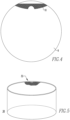
- Figures lA and 2 show a conventional blanking tool 2 having a 4-point shear 4 for cutting or shearing blanks 6 from material 8 (e.g., without limitation, sheet metal), as shown in Figure 3 .
- material 8 e.g., without limitation, sheet metal
- the shear 4 is compressed against the material 8 to cut or shear the blanks 6 ( Figures 3 and 4 ).
- the shear 4 and, in particular, a number of high points 10,12,14,16,18,20,22,24 e.g., surfaces which extend outwardly from the bottom of the blanking tool 2, as best shown in Figure 2 ) of the shear 4, engage and are compressed against the material 8.
- the contact areas, or locations at which the high points 10,12,14,16,18,20,22,24 engage the material 8, are best shown in Figure 3 .
- high points 10,12,14,16 at least partially engage, and are compressed against, the product area 26 of the material 8, whereas high points 18,20,22,24 engage the web 28 (e.g., the area of scrap material between blanks 6, sometimes referred to as the "skeleton") of the material 8.
- the product area 26 is the area which is subsequently formed into a cup 30 ( Figure 5 ).
- the high points 10,12,14,16 can undesirably scratch or otherwise blemish (e.g., without limitation, scuff; mar) the blank 6 ( Figure 4 ), which can translate into a defect in the cup 30 ( Figure 5 ), and ultimately cause a problem with the finished product (e.g., without limitation, beer/beverage can; food can) (not shown)).
- blemished area 32 in the cup 30 of Figure 5 resulting from the contact area 10 ( Figures 3 and 4 ) of the shear 4 engaging and damaging the blank 6 ( Figures 3 and 4 ) during the blanking process.
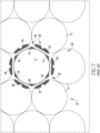
- the same problems are associated with conventional blanking tools 52 ( Figure 6A ) having a 6-point shear 54 ( Figure 6A ).
- the 6-point shear 54 includes a number of high points 60,62,64,66,68,70,72,74,76,78,80,82, which engage and are compressed against the material 8' when forming blanks 6', as shown in Figure 7 . That is, high points 60,62,64,66,68,70 engage, and are compressed against, the product area 26' of the web 8' during the blanking process.
- High points 72,74,76,78,80,82 engage the web 28' (e.g., the area of scrap material between blanks 6') of the material 8'. Accordingly, like the 4-point shear 4 discussed hereinabove with respect to Figures 1A-4 , portions of the 6-point shear 54 also engages and, therefore, can scratch or otherwise blemish (e.g., without limitation, scuff; mar) the blank 6' ( Figure 7 ).
- WO 2009019832 A1 discloses a blanking tool, a blank for metallic can, and method for manufacturing the metallic can.
- US 5,052,207 A discloses an apparatus for, and a method of, cutting a blank.
- US 5,604,044 A discloses blanks for sheet material forming process.
- the invention provides a blanking tool according to the features of claim 1 and a method according to the features of claim 10.
- the blanking tool effectively shears blanks without contacting the blanks themselves and potentially causing damage (e.g., without limitation, scratched or otherwise blemished).
- Embodiments of the disclosed concept will be described as applied to cutting (e.g., shearing) blanks from a sheet of material (e.g., without limitation, sheet metal) to subsequently form cups and containers (e.g., without limitation, beverage/beer cans; food cans) from the blanks, although it will become apparent that they could also be employed in arrangements, which fall outside the scope of the invention,to suitably cut (e.g., shear) blanks of any known or suitable material for a wide variety of different purposes and uses.
- a sheet of material e.g., without limitation, sheet metal
- cups and containers e.g., without limitation, beverage/beer cans; food cans
- fastener and “fastening mechanism” refers to any suitable connecting or tightening mechanism for securing one component to another expressly including, but not limited to, bolts and the combinations of bolts and nuts (e.g., without limitation, lock nuts) and bolts, washers and nuts.
- number shall mean one or an integer greater than one (i.e., a plurality).
- Figures 8 and 9A show a blanking tool 102 for use with a tooling assembly 300 ( Figure 15 ) of a press 400 ( Figure 15 ).
- the blanking tool 102 is a six-point shear 104 (i.e., cutedge), although it will be appreciated that the disclosed concept could be employed with a shear (not shown) having any known or suitable alternative number, shape and/or configuration of points (e.g., without limitation, a four-point shear (not shown)).
- the example shear 104 includes opposing first and second sides 106,108, an outer diameter 110, and an inner diameter 112.
- the specific dimensions of the outer diameter 110 and the inner diameter 112 are not meant to be limiting aspects of the disclosed concept. It will be appreciated, however, that the inner diameter 112 of the shear 104 is generally the same size as the diameter of the blanks 6" ( Figure 10 ), which are cut (e.g., sheared) by the shear 104.
- a plurality of contact surfaces 118,120,122,124,126,128 (six are shown) are disposed on the second side 108 of the shear 104.
- the contact surfaces 118,120,122,124,126,128 constitute high points, or locations which extend outwardly from the second side 108 of the shear 104.
- the contact surfaces 118,120,122,124,126,128 are formed by machining (e.g., without limitation, grinding) the second side 108 of the shear 104 to form a plurality of machined surfaces 130,132,134,136,138,140, each of which is disposed between a corresponding pair of the aforementioned contact surfaces 118,120,122,124,126,128.
- the disclosed concept involves selective machining of the blanking tool 102 to control the manner in which the shear 104 engages the material 8" ( Figure 10 ) from which blanks 6" ( Figure 10 ) are made.
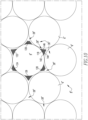
- the contact areas 118,120,122,124,126,128 (e.g., pattern and/or location of contact) of the shear 104 ( Figures 8 , 9A , 11, 12 , 14 and 15 ) with respect to the material 8" ( Figure 10 ), are best shown in Figures 9B and 10 .
- the material 8" will include a product area 26", corresponding to the area of the material 8" where the blanks 6" are located, and a web or skeleton 28", corresponding to the area of scrap material between such blanks 6".
- the disclosed shear 104 does not contact the product area 26" of the material 8". Therefore, the blanks 6" are effectively sheared, without being contacted or damaged (e.g., without limitation, scratched or otherwise blemished).
- problems known to be associated with the prior art such as damage caused to blanks (see blanks 6 of Figures 3 and 4 ; see also blanks 6' of Figure 7 ) by the shear (see shear 4 of Figures 1A and 2 ; see also shear 54 of Figure 6A ), or by the stock plate (see, for example, stock plate 306 of Figures 15 and 16 ), during the blanking process resulting in a defect in the cup (see, for example, blemished cup 30 of Figure 5 ), and ultimately in a potentially flawed finished product (e.g., without limitation, can body (not shown)), is eliminated.
- each contact area 118,120,122,124,126,128 of the shear 104 is preferably shaped substantially similarly to the web or skeleton 28" of the material 8".
- contact area 118 for example, includes three arcuate sides 142,144,146.
- the first arcuate side 142 is substantially flush with respect to the inner edge of the shear 104, which defines the inner diameter 112 thereof, as shown in Figure 11 .
- the second arcuate side 144 is shaped substantially similarly to, and is generally parallel with respect to, the opposing corresponding arcuate portion of the web 28" , which is defined by the removal of the blank 6" adjacent to side 144.
- the third arcuate side 146 is shaped substantially similarly to, and is generally parallel with respect to, the opposing corresponding arcuate portion of the web 28", which is defined by the removal of the blank 6" adjacent to side 146.
- the contact area 118 generally has a triangular shape corresponding to the generally triangular shape of the corresponding portion of the web 28" of material 8", wherein each of the arcuate sides 142,144,146 is concave, as shown. It will, however, be appreciated that any known or suitable alternative number, shape and/or configuration of contact areas (not shown) could be employed to engage only the web 28" of the material 8" in accordance with the disclosed concept.
- Figures 11 and 12 show a grinding wheel 200 (shown in simplified form in phantom line drawing; also shown in Figure 12 in an alternative vertical orientation) machined (e.g., without limitation, grinding) surface 130 to form the desired high-point contact areas 118,128 ( Figure 11 ) by removing material from the second side 108 of the shear 104, between the contact areas 118,128, as previously discussed.
- the machined surfaces for example surface 130, between contact areas, for example contact areas 118,128, is preferably machined to have a desired predetermined shear angle 190 (best shown in the enlarged section view of Figure 14 ).
- the shear angle 190 of Figure 14 Comparing the shear angle 190 of Figure 14 to the shear angle 90 of the prior art blanking tool 2 of Figure 13 , it will be appreciated that the machined surface 130 follows, or is disposed at, the shear angle 190, whereas the prior art shear 4 of Figure 13 has no equivalent machined surface, and does not follow the shear angle 90 but rather includes an additional high point or contact area (see, for example, high point 10 of shear 4 of Figures 1A and 2 ).
- the shear angle 190 is greater than the shear angle 90 of the prior art shear of Figure 13 , although it will be appreciated that the specific dimension of the shear angle 190 is not meant to be a limiting aspect of the disclosed concept.
- the shear angle 190 in accordance with one non-limiting embodiment of the disclosed concept could be up to about 30 degrees.
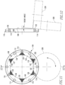
- Figures 15 and 16 show the disclosed blanking tool 102 employed with a tooling assembly 300 of a press 400 (partially shown in section view), in accordance with a non-limiting embodiment of the disclosed concept.
- the tooling assembly 300 includes first tooling (e.g., upper tooling from the perspective of Figures 15 and 16 , indicated generally by reference 302) and second tooling (e.g., lower tooling from the perspective of Figures 15 and 16 , indicated generally by reference 304), which is disposed opposite from the upper tooling 302.
- the aforementioned sheet of material 8" (shown in simplified form in phantom line drawing in Figures 15 and 16 ) is fed into the press 400 between the upper tooling 302 and lower tooling 304.
- the shear 104 is coupled to the upper tooling 302 using any known or suitable fastening mechanism.
- the shear 104 shown and described herein includes a number of bolt holes 114,116 (shown in Figures 9A , 11 and 12 ; not shown in Figure 8 for simplicity of illustration) for bolting the blanking tool 102 to the upper tooling 302.
- the sheet of material 8" is fed into the press 400, for example from a coil (not shown) or stack of such sheets (not shown), and the press 400 is actuated to advance the upper tooling 302 and, in particular, the shear 104, toward the lower tooling 304 and, in particular the stock plate 306, such that the material 8" is engaged and cut (e.g., shears) the material 8" to form the aforementioned blanks 6" ( Figure 10 ).
- the stock plate 306 supports the material 8" as it is fed through the tooling assembly 300 (e.g., without limitation, die set).
- the aforementioned contact areas 118,120,122,124,126,128 (all shown in Figures 9A-11 ) of the shear 104 contact only the web or skeleton 28" of the material 8", as shown in Figure 10 and as previously described hereinabove with respect thereto.
- the stock plate 306 is resilient (e.g., without limitation, supported by springs, pneumatically, or hydraulically) to allow it to move downward as the shear 104 pushes against it, with the material 8" trapped therebetween.
- the stock plate 306 helps to lift the web or skeleton 28" ( Figure 10 ) portion of the material 8" while the blank 6" ( Figure 10 ) is drawn down through the blank and draw die 308 to form a cup (not shown, but see cup 30 of Figure 5 ).
- a further advantage of the disclosed blanking tool 102 is longer tool life. That is, in operation, the prior art shear (see, for example, shear 4 of Figures 1A and 2 ) impacts the stock plate 306 (with material 8" sandwiched therebetween) at relatively high speeds and tonnage, such that areas of the stock plate 306 opposite certain high points (see, for example, high points 18,20,22,24 of Figures 1A-3 ) of the shear 4 ( Figures 1A and 2 ) become worn.
- the disclosed shear 104 employs fewer contact areas 118,120,122,124,126,128 (six are shown), wherein each of the contact areas 118,120,122,124,126,128 has a relatively large surface area (compare, for example, the relatively small surface area of high points 18,20,22,24 of shear 4 of Figures 1A and 2 , to the relatively large surface area of high points 118,120,122,124,126,128 of the disclosed shear 104 ( Figures 8 , 9A and 11 )).
- This improved design, with increased surface area advantageously provides greater and more even load distribution of the impact load form the shear 104 than the prior art design. Accordingly, less wear to the stock plate 306 occurs.
- the blanking tool 102 may optionally further include a carbide ring 310 inserted into the shear 104, as shown for example and without limitation in Figure 16 . That is, because carbide is very hard, the cutting or blanking edge of the tool 102 will last longer if the carbide ring 310 is employed. It will be appreciated that the carbide ring 310 preferably does not have any bearing on the geometry of the blanking tool 102.
- the disclosed blanking tool 102 provides a shear 104 for effectively cutting (e.g., shearing) blanks 6" ( Figure 10 ), without engaging any portion of each blank 6" ( Figure 10 ). Therefore, damage (e.g., without limitation, scratching or otherwise blemishing) of the blank 6" during the blanking process is eliminated, thereby eliminating the potential for contact defects in the cup (see blemished cup 30 of Figure 5 ) or end product (e.g., without limitation, container; beer/beverage can; food can (not shown)) formed from the blank 6", which is known to be associated with prior art blanking tools (see blanking tool 2 of Figures 1A and 2 ; see also blanking tool 52 of Figure 6A ).
- end product e.g., without limitation, container; beer/beverage can; food can (not shown)
Landscapes
- Engineering & Computer Science (AREA)
- Mechanical Engineering (AREA)
- Shaping Metal By Deep-Drawing, Or The Like (AREA)
- Perforating, Stamping-Out Or Severing By Means Other Than Cutting (AREA)
- Punching Or Piercing (AREA)
- Mounting, Exchange, And Manufacturing Of Dies (AREA)
Applications Claiming Priority (2)
| Application Number | Priority Date | Filing Date | Title |
|---|---|---|---|
| US31231610P | 2010-03-10 | 2010-03-10 | |
| PCT/US2011/026438 WO2011112376A1 (en) | 2010-03-10 | 2011-02-28 | Tooling assembly, blanking tool therefor and associated method |
Publications (3)
| Publication Number | Publication Date |
|---|---|
| EP2544837A1 EP2544837A1 (en) | 2013-01-16 |
| EP2544837A4 EP2544837A4 (en) | 2016-12-28 |
| EP2544837B1 true EP2544837B1 (en) | 2023-06-28 |
Family
ID=44558684
Family Applications (1)
| Application Number | Title | Priority Date | Filing Date |
|---|---|---|---|
| EP11753794.4A Active EP2544837B1 (en) | 2010-03-10 | 2011-02-28 | Tooling assembly, blanking tool therefor and associated method |
Country Status (5)
| Country | Link |
|---|---|
| US (2) | US20110219926A1 (zh) |
| EP (1) | EP2544837B1 (zh) |
| JP (1) | JP5792751B2 (zh) |
| CN (1) | CN102791398B (zh) |
| WO (1) | WO2011112376A1 (zh) |
Families Citing this family (2)
| Publication number | Priority date | Publication date | Assignee | Title |
|---|---|---|---|---|
| CN112372929B (zh) * | 2020-10-20 | 2023-12-22 | 浙江致一智能机器人有限公司 | 一种用于杯盖装配的剪切机构 |
| CN112571515A (zh) * | 2020-11-16 | 2021-03-30 | 北京航星机器制造有限公司 | 一种冲裁设备 |
Citations (1)
| Publication number | Priority date | Publication date | Assignee | Title |
|---|---|---|---|---|
| US20030159561A1 (en) * | 2002-02-28 | 2003-08-28 | Nordlin William F. | Knockout punch with pilot hole locator |
Family Cites Families (77)
| Publication number | Priority date | Publication date | Assignee | Title |
|---|---|---|---|---|
| US353439A (en) * | 1886-11-30 | Half to archibald w | ||
| US1375305A (en) * | 1921-04-19 | Battery-electrodes | ||
| US1431541A (en) * | 1922-10-10 | Machine for cutting bisks ebom sheet material | ||
| US155098A (en) * | 1874-09-15 | Improvement in presses for making tin-can tops | ||
| US384532A (en) * | 1888-06-12 | Punch | ||
| US2735489A (en) * | 1956-02-21 | fowler | ||
| US110396A (en) | 1870-12-20 | Improvement in vehicles | ||
| US1103966A (en) * | 1913-06-11 | 1914-07-21 | Emil F Holinger | Manufacturing seamless tubes. |
| US1202546A (en) * | 1914-07-03 | 1916-10-24 | Mcdonald Machine Co | Process for forming scroll-edge metal blanks. |
| US1369234A (en) * | 1920-01-12 | 1921-02-22 | Theodore J Freund | Punch |
| US1621811A (en) * | 1922-08-24 | 1927-03-22 | Otis K Richard | Punch and die retainer |
| US1817223A (en) * | 1928-01-25 | 1931-08-04 | Greenlee Bros & Co | Metal punch |
| US2086435A (en) * | 1936-05-12 | 1937-07-06 | Rapp Alphonse | Washer cutting tool |
| US2096778A (en) * | 1936-10-19 | 1937-10-26 | Azer Albert | Punch |
| US2545237A (en) * | 1946-01-16 | 1951-03-13 | Maby Per Gunnar | Punching tool |
| US2928451A (en) * | 1955-02-07 | 1960-03-15 | Wales Strippit Corp | Self contained perforating and countersinking unit |
| US3060992A (en) * | 1960-01-11 | 1962-10-30 | Hopp | Means and method for forming non-planar articles |
| US3263465A (en) * | 1961-12-14 | 1966-08-02 | Arthur L Way | Apparatus for and method of severing and sealing hollow conduit |
| US3252315A (en) * | 1962-03-30 | 1966-05-24 | Lyon Inc | Apparatus for manufacturing wheel covers |
| US3319452A (en) * | 1963-10-07 | 1967-05-16 | Rohr Corp | Corrugation punch press |
| US3496753A (en) * | 1966-10-03 | 1970-02-24 | North American Rockwell | Method of making wheel trim or covers |
| US3606565A (en) * | 1969-06-26 | 1971-09-20 | Continental Ind Inc | Self-punching t fitting |
| US3683499A (en) * | 1970-08-07 | 1972-08-15 | Makrite Inc | Unitary piercing punch device |
| US3656394A (en) * | 1970-08-10 | 1972-04-18 | Tally Corp | Punch configuration |
| JPS5251346Y2 (zh) * | 1973-01-25 | 1977-11-21 | ||
| US3790876A (en) | 1973-02-15 | 1974-02-05 | Rockwell International Corp | Paper cutting machine |
| US3996832A (en) * | 1975-04-10 | 1976-12-14 | Standard Oil Company (Indiana) | Punch for producing holes in foamed thermoplastic containers |
| US4002092A (en) * | 1975-06-11 | 1977-01-11 | B & M Die Co., Inc. | Compound angle cutting edge and method of using same |
| JPS5653827A (en) * | 1979-10-08 | 1981-05-13 | Honda Eng Kk | Extracting method of approximately circular blank material |
| JPS56134026A (en) * | 1980-03-25 | 1981-10-20 | Tsubakimoto Chain Co | Blanking method |
| US4277891A (en) * | 1980-06-13 | 1981-07-14 | American Optical Corporation | Lens tape cutter |
| US4403417A (en) * | 1982-06-04 | 1983-09-13 | Wilson Stephen K | Draw punch |
| CA1228822A (en) * | 1982-09-29 | 1987-11-03 | Sam C. Pulciani | Container end wall construction |
| US4846033A (en) * | 1985-07-01 | 1989-07-11 | Km-Engineering Ag | Apparatus for making blanks and strips of blanks |
| US4880131A (en) * | 1987-11-13 | 1989-11-14 | Van Dorn Company | Ringless paint container |
| US5024077A (en) * | 1988-01-11 | 1991-06-18 | Redicon Corporation | Method for forming container with profiled bottom |
| US4899447A (en) * | 1988-01-22 | 1990-02-13 | Greenlee Textron Inc. | Panel punch |
| JPH01284433A (ja) * | 1988-05-10 | 1989-11-15 | Mitsubishi Electric Corp | プレス型 |
| US5056392A (en) * | 1988-08-19 | 1991-10-15 | Mate Punch & Die Co. | Punch assembly |
| US4977772A (en) * | 1988-09-02 | 1990-12-18 | Redicon Corporation | Method and apparatus for forming reforming and curling shells in a single press |
| EP0367642B1 (fr) * | 1988-10-05 | 1993-04-21 | Sollac | Procédé et dispositif de formage d'un flan de tôle notamment pour réaliser un masque de tube cathodique obtenu selon ce procédé |
| US5052258A (en) * | 1989-03-16 | 1991-10-01 | Hunter Theodore K | Cutter |
| GB8917049D0 (en) * | 1989-07-26 | 1989-09-13 | Metal Box Plc | An apparatus for,and a method of,cutting a blank |
| JPH0757390B2 (ja) * | 1989-11-13 | 1995-06-21 | 東洋製罐株式会社 | 再絞り方法 |
| US5029392A (en) * | 1990-08-08 | 1991-07-09 | Ideal Industries, Inc. | Two point punch |
| GB2255304B (en) * | 1991-04-26 | 1994-07-20 | Toyota Motor Co Ltd | Piercing die whose punch has different amounts of chamfer at different outer peripheral edge portions |
| US5604044A (en) | 1992-12-28 | 1997-02-18 | Mccabe; Charles J. | Blanks for sheet material forming process |
| US5802907A (en) * | 1993-03-12 | 1998-09-08 | Stodd; Ralph P. | Tooling apparatus and method for high speed production of drawn metal cup-like articles |
| US5638717A (en) * | 1993-03-12 | 1997-06-17 | Stodd; Ralph P. | Tooling apparatus for high speed production of drawn metal cup-like articles |
| US5442947A (en) * | 1993-03-12 | 1995-08-22 | Stodd; Ralph P. | Tooling apparatus and method for high speed production of drawn metal cup-like articles |
| US5394727A (en) * | 1993-08-18 | 1995-03-07 | Aluminum Company Of America | Method of forming a metal container body |
| US5423240A (en) * | 1993-11-18 | 1995-06-13 | Detorre; Robert P. | Side-crowned carbide cutting blades and cutting devices |
| GB9417299D0 (en) * | 1994-08-27 | 1994-10-19 | Metal Box Plc | Production of metal containers |
| US5727436A (en) * | 1995-03-27 | 1998-03-17 | Ideal Industries, Inc. | Draw punch having relieved helical working faces |
| US5628224A (en) * | 1995-05-05 | 1997-05-13 | Can Industry Products, Inc. | Method for sequentially forming can bodies |
| GB9510572D0 (en) * | 1995-05-26 | 1995-07-19 | Metal Box Plc | Containers |
| US5630337A (en) * | 1995-09-07 | 1997-05-20 | Werth; Elmer D. | Apparatus and method for forming a container |
| US5626048A (en) * | 1995-11-20 | 1997-05-06 | Can Industry Products, Inc. | Method and apparatus for forming cup-shaped members |
| US5881593A (en) * | 1996-03-07 | 1999-03-16 | Redicon Corporation | Method and apparatus for forming a bottom-profiled cup |
| US5881611A (en) * | 1997-01-07 | 1999-03-16 | Serigraph, Inc. | Punch button and process |
| US6070507A (en) * | 1997-03-03 | 2000-06-06 | Abbott Laboratories | Method for punching a sealed package from first and second webs |
| USD397277S (en) * | 1997-06-18 | 1998-08-25 | Gibbs Jr William E | Bread cutter |
| UY25210A1 (es) * | 1997-10-16 | 1999-04-09 | Cosma Int Inc | Troquel estampador de deformacion para la estampacion de paneles de carroceria de vehiculos a motor. |
| NL1008468C2 (nl) * | 1998-03-04 | 1999-09-07 | Hoogovens Staal Bv | Werkwijze voor de vervaardiging van een bus door wandstrekken. |
| JP2001025830A (ja) * | 1999-07-13 | 2001-01-30 | Fuji Dies Kk | 打ち抜き金型 |
| EP1134046B1 (en) * | 1999-08-30 | 2005-08-03 | Daiwa Can Company | Production method for bottle type can and form-working tool |
| US6539767B2 (en) * | 2000-08-31 | 2003-04-01 | Sequa Can Machinery, Inc. | Method and apparatus for forming a container component |
| US7070729B2 (en) * | 2002-09-06 | 2006-07-04 | Fort James Corporation | Pressware die set with product ejectors at outer forming surfaces |
| US20050056133A1 (en) * | 2003-09-16 | 2005-03-17 | Chien-Kai Huang | Paper punch pin |
| US7228776B2 (en) * | 2003-11-13 | 2007-06-12 | Case Gerald A | Punch assembly |
| US7819790B2 (en) * | 2004-02-20 | 2010-10-26 | Dixie Consumer Products Llc | Apparatus for making paperboard pressware with controlled blank feed |
| US7240531B2 (en) * | 2005-02-25 | 2007-07-10 | Stolle Machinery Company, Llc | Press for forming containers with profiled bottoms |
| US7124613B1 (en) * | 2005-07-28 | 2006-10-24 | Stolle Machinery Company, Llc | Press and method of manufacturing a can end |
| JP2009037980A (ja) * | 2007-08-03 | 2009-02-19 | Panasonic Corp | 電池缶および金属缶用ブランクとこれを用いた電池缶および金属缶の製造方法 |
| US8474689B2 (en) * | 2008-12-15 | 2013-07-02 | Dixie Consumer Products Llc | Method for in-die lamination of plural layers of material and paper-containing product made thereby |
| CA2797352A1 (en) * | 2011-12-09 | 2013-06-09 | Greenlee Textron Inc. | Punch assembly |
| US9393607B2 (en) * | 2013-04-30 | 2016-07-19 | Textron Innovations Inc. | Die with profiled base wall and its associated punch |
-
2011
- 2011-02-28 EP EP11753794.4A patent/EP2544837B1/en active Active
- 2011-02-28 JP JP2012557078A patent/JP5792751B2/ja active Active
- 2011-02-28 CN CN201180013054.6A patent/CN102791398B/zh active Active
- 2011-02-28 WO PCT/US2011/026438 patent/WO2011112376A1/en active Application Filing
- 2011-02-28 US US13/036,103 patent/US20110219926A1/en not_active Abandoned
-
2016
- 2016-12-12 US US15/375,482 patent/US10710140B2/en active Active
Patent Citations (1)
| Publication number | Priority date | Publication date | Assignee | Title |
|---|---|---|---|---|
| US20030159561A1 (en) * | 2002-02-28 | 2003-08-28 | Nordlin William F. | Knockout punch with pilot hole locator |
Also Published As
| Publication number | Publication date |
|---|---|
| US20170087618A1 (en) | 2017-03-30 |
| US10710140B2 (en) | 2020-07-14 |
| JP5792751B2 (ja) | 2015-10-14 |
| EP2544837A1 (en) | 2013-01-16 |
| EP2544837A4 (en) | 2016-12-28 |
| CN102791398A (zh) | 2012-11-21 |
| WO2011112376A1 (en) | 2011-09-15 |
| US20110219926A1 (en) | 2011-09-15 |
| JP2013522044A (ja) | 2013-06-13 |
| CN102791398B (zh) | 2015-04-15 |
Similar Documents
| Publication | Publication Date | Title |
|---|---|---|
| JP6634385B2 (ja) | リングプル式の瓶の王冠を製造するためのシステムおよび関連する方法 | |
| EP2490836B1 (en) | Container, and selectively formed cup, tooling and associated method for providing same | |
| US9248489B2 (en) | Press-forming method and press-forming apparatus | |
| KR20090028471A (ko) | 작업편을 정밀 블랭킹 하고 성형하는 장치 및 방법 | |
| US8769790B2 (en) | Multi-piece self pierce rivet die for improved die life | |
| US8365569B2 (en) | Method and tool for the production of three-dimensional attachments by forming and fine blanking operations | |
| US10710140B2 (en) | Tooling assembly, blanking tool therefor and associated method | |
| US20230016790A1 (en) | Can end with a coined rivet, tooling assembly therefor and a method of forming | |
| CN113412170A (zh) | 转换压制机端部保持杆组件 | |
| CN104874666A (zh) | 一种车架加强板冷冲压工艺 | |
| US11458526B2 (en) | Method of machining an opening in a plurality of blanks | |
| CN112118919A (zh) | 使用拉伸工艺形成罐壳体的方法和装置 | |
| JP2021511263A (ja) | 拡張可能リベットボタンを備えたシェル及びそのためのツーリング | |
| JP2021511213A (ja) | 拡張可能バブルを備えたシェル及びそのためのツーリング | |
| Joshi | Press tools design and construction | |
| US20120177464A1 (en) | Crown type eccentric multi die press for manufacturing reinforced crown caps and embossed crown caps | |
| CN111604416A (zh) | 一种用于卡车斜锥加工的冲压系统 | |
| CA2340536C (en) | Method of deep drawing heavy-gage parts and related apparatus and article | |
| US20130098218A1 (en) | Stamping Press | |
| CN212469447U (zh) | 一种用于卡车斜锥加工的冲压系统 | |
| CN216546418U (zh) | 卡车备胎架用变截面横梁 | |
| JP2003117628A (ja) | 鍛造プレス | |
| KR20240010247A (ko) | 상용차용 스틸 휠 디스크의 플랜지 가공장치 | |
| RU2322321C2 (ru) | Штамп для вырубки и многопереходной вытяжки |
Legal Events
| Date | Code | Title | Description |
|---|---|---|---|
| PUAI | Public reference made under article 153(3) epc to a published international application that has entered the european phase |
Free format text: ORIGINAL CODE: 0009012 |
|
| 17P | Request for examination filed |
Effective date: 20120903 |
|
| AK | Designated contracting states |
Kind code of ref document: A1 Designated state(s): AL AT BE BG CH CY CZ DE DK EE ES FI FR GB GR HR HU IE IS IT LI LT LU LV MC MK MT NL NO PL PT RO RS SE SI SK SM TR |
|
| DAX | Request for extension of the european patent (deleted) | ||
| RA4 | Supplementary search report drawn up and despatched (corrected) |
Effective date: 20161125 |
|
| RIC1 | Information provided on ipc code assigned before grant |
Ipc: B21D 28/06 20060101AFI20161121BHEP |
|
| STAA | Information on the status of an ep patent application or granted ep patent |
Free format text: STATUS: EXAMINATION IS IN PROGRESS |
|
| 17Q | First examination report despatched |
Effective date: 20200218 |
|
| STAA | Information on the status of an ep patent application or granted ep patent |
Free format text: STATUS: EXAMINATION IS IN PROGRESS |
|
| GRAP | Despatch of communication of intention to grant a patent |
Free format text: ORIGINAL CODE: EPIDOSNIGR1 |
|
| STAA | Information on the status of an ep patent application or granted ep patent |
Free format text: STATUS: GRANT OF PATENT IS INTENDED |
|
| INTG | Intention to grant announced |
Effective date: 20230227 |
|
| GRAS | Grant fee paid |
Free format text: ORIGINAL CODE: EPIDOSNIGR3 |
|
| GRAA | (expected) grant |
Free format text: ORIGINAL CODE: 0009210 |
|
| STAA | Information on the status of an ep patent application or granted ep patent |
Free format text: STATUS: THE PATENT HAS BEEN GRANTED |
|
| P01 | Opt-out of the competence of the unified patent court (upc) registered |
Effective date: 20230429 |
|
| AK | Designated contracting states |
Kind code of ref document: B1 Designated state(s): AL AT BE BG CH CY CZ DE DK EE ES FI FR GB GR HR HU IE IS IT LI LT LU LV MC MK MT NL NO PL PT RO RS SE SI SK SM TR |
|
| REG | Reference to a national code |
Ref country code: GB Ref legal event code: FG4D |
|
| REG | Reference to a national code |
Ref country code: CH Ref legal event code: EP |
|
| REG | Reference to a national code |
Ref country code: AT Ref legal event code: REF Ref document number: 1582245 Country of ref document: AT Kind code of ref document: T Effective date: 20230715 |
|
| REG | Reference to a national code |
Ref country code: IE Ref legal event code: FG4D |
|
| REG | Reference to a national code |
Ref country code: DE Ref legal event code: R096 Ref document number: 602011074019 Country of ref document: DE |
|
| REG | Reference to a national code |
Ref country code: NL Ref legal event code: FP |
|
| REG | Reference to a national code |
Ref country code: LT Ref legal event code: MG9D |
|
| PG25 | Lapsed in a contracting state [announced via postgrant information from national office to epo] |
Ref country code: SE Free format text: LAPSE BECAUSE OF FAILURE TO SUBMIT A TRANSLATION OF THE DESCRIPTION OR TO PAY THE FEE WITHIN THE PRESCRIBED TIME-LIMIT Effective date: 20230628 Ref country code: NO Free format text: LAPSE BECAUSE OF FAILURE TO SUBMIT A TRANSLATION OF THE DESCRIPTION OR TO PAY THE FEE WITHIN THE PRESCRIBED TIME-LIMIT Effective date: 20230928 |
|
| REG | Reference to a national code |
Ref country code: AT Ref legal event code: MK05 Ref document number: 1582245 Country of ref document: AT Kind code of ref document: T Effective date: 20230628 |
|
| PG25 | Lapsed in a contracting state [announced via postgrant information from national office to epo] |
Ref country code: RS Free format text: LAPSE BECAUSE OF FAILURE TO SUBMIT A TRANSLATION OF THE DESCRIPTION OR TO PAY THE FEE WITHIN THE PRESCRIBED TIME-LIMIT Effective date: 20230628 Ref country code: LV Free format text: LAPSE BECAUSE OF FAILURE TO SUBMIT A TRANSLATION OF THE DESCRIPTION OR TO PAY THE FEE WITHIN THE PRESCRIBED TIME-LIMIT Effective date: 20230628 Ref country code: LT Free format text: LAPSE BECAUSE OF FAILURE TO SUBMIT A TRANSLATION OF THE DESCRIPTION OR TO PAY THE FEE WITHIN THE PRESCRIBED TIME-LIMIT Effective date: 20230628 Ref country code: HR Free format text: LAPSE BECAUSE OF FAILURE TO SUBMIT A TRANSLATION OF THE DESCRIPTION OR TO PAY THE FEE WITHIN THE PRESCRIBED TIME-LIMIT Effective date: 20230628 Ref country code: GR Free format text: LAPSE BECAUSE OF FAILURE TO SUBMIT A TRANSLATION OF THE DESCRIPTION OR TO PAY THE FEE WITHIN THE PRESCRIBED TIME-LIMIT Effective date: 20230929 |
|
| PG25 | Lapsed in a contracting state [announced via postgrant information from national office to epo] |
Ref country code: FI Free format text: LAPSE BECAUSE OF FAILURE TO SUBMIT A TRANSLATION OF THE DESCRIPTION OR TO PAY THE FEE WITHIN THE PRESCRIBED TIME-LIMIT Effective date: 20230628 |
|
| PG25 | Lapsed in a contracting state [announced via postgrant information from national office to epo] |
Ref country code: SK Free format text: LAPSE BECAUSE OF FAILURE TO SUBMIT A TRANSLATION OF THE DESCRIPTION OR TO PAY THE FEE WITHIN THE PRESCRIBED TIME-LIMIT Effective date: 20230628 |
|
| PG25 | Lapsed in a contracting state [announced via postgrant information from national office to epo] |
Ref country code: ES Free format text: LAPSE BECAUSE OF FAILURE TO SUBMIT A TRANSLATION OF THE DESCRIPTION OR TO PAY THE FEE WITHIN THE PRESCRIBED TIME-LIMIT Effective date: 20230628 |
|
| PG25 | Lapsed in a contracting state [announced via postgrant information from national office to epo] |
Ref country code: IS Free format text: LAPSE BECAUSE OF FAILURE TO SUBMIT A TRANSLATION OF THE DESCRIPTION OR TO PAY THE FEE WITHIN THE PRESCRIBED TIME-LIMIT Effective date: 20231028 |
|
| PG25 | Lapsed in a contracting state [announced via postgrant information from national office to epo] |
Ref country code: SM Free format text: LAPSE BECAUSE OF FAILURE TO SUBMIT A TRANSLATION OF THE DESCRIPTION OR TO PAY THE FEE WITHIN THE PRESCRIBED TIME-LIMIT Effective date: 20230628 Ref country code: SK Free format text: LAPSE BECAUSE OF FAILURE TO SUBMIT A TRANSLATION OF THE DESCRIPTION OR TO PAY THE FEE WITHIN THE PRESCRIBED TIME-LIMIT Effective date: 20230628 Ref country code: RO Free format text: LAPSE BECAUSE OF FAILURE TO SUBMIT A TRANSLATION OF THE DESCRIPTION OR TO PAY THE FEE WITHIN THE PRESCRIBED TIME-LIMIT Effective date: 20230628 Ref country code: PT Free format text: LAPSE BECAUSE OF FAILURE TO SUBMIT A TRANSLATION OF THE DESCRIPTION OR TO PAY THE FEE WITHIN THE PRESCRIBED TIME-LIMIT Effective date: 20231030 Ref country code: IS Free format text: LAPSE BECAUSE OF FAILURE TO SUBMIT A TRANSLATION OF THE DESCRIPTION OR TO PAY THE FEE WITHIN THE PRESCRIBED TIME-LIMIT Effective date: 20231028 Ref country code: ES Free format text: LAPSE BECAUSE OF FAILURE TO SUBMIT A TRANSLATION OF THE DESCRIPTION OR TO PAY THE FEE WITHIN THE PRESCRIBED TIME-LIMIT Effective date: 20230628 Ref country code: EE Free format text: LAPSE BECAUSE OF FAILURE TO SUBMIT A TRANSLATION OF THE DESCRIPTION OR TO PAY THE FEE WITHIN THE PRESCRIBED TIME-LIMIT Effective date: 20230628 Ref country code: CZ Free format text: LAPSE BECAUSE OF FAILURE TO SUBMIT A TRANSLATION OF THE DESCRIPTION OR TO PAY THE FEE WITHIN THE PRESCRIBED TIME-LIMIT Effective date: 20230628 Ref country code: AT Free format text: LAPSE BECAUSE OF FAILURE TO SUBMIT A TRANSLATION OF THE DESCRIPTION OR TO PAY THE FEE WITHIN THE PRESCRIBED TIME-LIMIT Effective date: 20230628 |
|
| PG25 | Lapsed in a contracting state [announced via postgrant information from national office to epo] |
Ref country code: PL Free format text: LAPSE BECAUSE OF FAILURE TO SUBMIT A TRANSLATION OF THE DESCRIPTION OR TO PAY THE FEE WITHIN THE PRESCRIBED TIME-LIMIT Effective date: 20230628 |
|
| PGFP | Annual fee paid to national office [announced via postgrant information from national office to epo] |
Ref country code: NL Payment date: 20240108 Year of fee payment: 14 |
|
| REG | Reference to a national code |
Ref country code: DE Ref legal event code: R097 Ref document number: 602011074019 Country of ref document: DE |
|
| PG25 | Lapsed in a contracting state [announced via postgrant information from national office to epo] |
Ref country code: DK Free format text: LAPSE BECAUSE OF FAILURE TO SUBMIT A TRANSLATION OF THE DESCRIPTION OR TO PAY THE FEE WITHIN THE PRESCRIBED TIME-LIMIT Effective date: 20230628 |
|
| PGFP | Annual fee paid to national office [announced via postgrant information from national office to epo] |
Ref country code: DE Payment date: 20231229 Year of fee payment: 14 Ref country code: GB Payment date: 20240108 Year of fee payment: 14 |
|
| PLBE | No opposition filed within time limit |
Free format text: ORIGINAL CODE: 0009261 |
|
| STAA | Information on the status of an ep patent application or granted ep patent |
Free format text: STATUS: NO OPPOSITION FILED WITHIN TIME LIMIT |