EP2544827B1 - Ventileinheit für eine beschichtungsanlage - Google Patents
Ventileinheit für eine beschichtungsanlage Download PDFInfo
- Publication number
- EP2544827B1 EP2544827B1 EP20110707801 EP11707801A EP2544827B1 EP 2544827 B1 EP2544827 B1 EP 2544827B1 EP 20110707801 EP20110707801 EP 20110707801 EP 11707801 A EP11707801 A EP 11707801A EP 2544827 B1 EP2544827 B1 EP 2544827B1
- Authority
- EP
- European Patent Office
- Prior art keywords
- valve
- housing part
- housing
- valve unit
- coating agent
- Prior art date
- Legal status (The legal status is an assumption and is not a legal conclusion. Google has not performed a legal analysis and makes no representation as to the accuracy of the status listed.)
- Active
Links
Images

Classifications
-
- B—PERFORMING OPERATIONS; TRANSPORTING
- B05—SPRAYING OR ATOMISING IN GENERAL; APPLYING FLUENT MATERIALS TO SURFACES, IN GENERAL
- B05B—SPRAYING APPARATUS; ATOMISING APPARATUS; NOZZLES
- B05B12/00—Arrangements for controlling delivery; Arrangements for controlling the spray area
- B05B12/14—Arrangements for controlling delivery; Arrangements for controlling the spray area for supplying a selected one of a plurality of liquids or other fluent materials or several in selected proportions to a spray apparatus, e.g. to a single spray outlet
- B05B12/149—Arrangements for controlling delivery; Arrangements for controlling the spray area for supplying a selected one of a plurality of liquids or other fluent materials or several in selected proportions to a spray apparatus, e.g. to a single spray outlet characterised by colour change manifolds or valves therefor
-
- B—PERFORMING OPERATIONS; TRANSPORTING
- B05—SPRAYING OR ATOMISING IN GENERAL; APPLYING FLUENT MATERIALS TO SURFACES, IN GENERAL
- B05B—SPRAYING APPARATUS; ATOMISING APPARATUS; NOZZLES
- B05B12/00—Arrangements for controlling delivery; Arrangements for controlling the spray area
- B05B12/14—Arrangements for controlling delivery; Arrangements for controlling the spray area for supplying a selected one of a plurality of liquids or other fluent materials or several in selected proportions to a spray apparatus, e.g. to a single spray outlet
- B05B12/1409—Arrangements for controlling delivery; Arrangements for controlling the spray area for supplying a selected one of a plurality of liquids or other fluent materials or several in selected proportions to a spray apparatus, e.g. to a single spray outlet the selection means being part of the discharge apparatus, e.g. part of the spray gun
-
- B—PERFORMING OPERATIONS; TRANSPORTING
- B05—SPRAYING OR ATOMISING IN GENERAL; APPLYING FLUENT MATERIALS TO SURFACES, IN GENERAL
- B05B—SPRAYING APPARATUS; ATOMISING APPARATUS; NOZZLES
- B05B5/00—Electrostatic spraying apparatus; Spraying apparatus with means for charging the spray electrically; Apparatus for spraying liquids or other fluent materials by other electric means
- B05B5/025—Discharge apparatus, e.g. electrostatic spray guns
- B05B5/04—Discharge apparatus, e.g. electrostatic spray guns characterised by having rotary outlet or deflecting elements, i.e. spraying being also effected by centrifugal forces
-
- B—PERFORMING OPERATIONS; TRANSPORTING
- B05—SPRAYING OR ATOMISING IN GENERAL; APPLYING FLUENT MATERIALS TO SURFACES, IN GENERAL
- B05B—SPRAYING APPARATUS; ATOMISING APPARATUS; NOZZLES
- B05B5/00—Electrostatic spraying apparatus; Spraying apparatus with means for charging the spray electrically; Apparatus for spraying liquids or other fluent materials by other electric means
- B05B5/025—Discharge apparatus, e.g. electrostatic spray guns
- B05B5/047—Discharge apparatus, e.g. electrostatic spray guns using tribo-charging
-
- Y—GENERAL TAGGING OF NEW TECHNOLOGICAL DEVELOPMENTS; GENERAL TAGGING OF CROSS-SECTIONAL TECHNOLOGIES SPANNING OVER SEVERAL SECTIONS OF THE IPC; TECHNICAL SUBJECTS COVERED BY FORMER USPC CROSS-REFERENCE ART COLLECTIONS [XRACs] AND DIGESTS
- Y10—TECHNICAL SUBJECTS COVERED BY FORMER USPC
- Y10T—TECHNICAL SUBJECTS COVERED BY FORMER US CLASSIFICATION
- Y10T137/00—Fluid handling
- Y10T137/6851—With casing, support, protector or static constructional installations
Definitions
- the invention relates to a valve unit for a coating system, in particular as an integrated color changer or two-component mixer in a rotary atomizer.
- WO 2007/131636 A1 is a rotary atomizer with an integrated color changer (English ICC: I unintegrated C olor C hanger) known, the color changer is structurally integrated into the housing of the rotary atomizer. Furthermore, it is off WO 2008/071273 A2 an annular construction for such a color changer, wherein the color changer is formed by a valve unit which is housed in a housing.
- the known valve unit essentially consists of a central coating agent channel, into which a plurality of coating agent supply lines open radially, wherein the feed from the individual coating agent supply lines into the central coating agent channel is controlled by radially extending needle valves.
- the housing of the valve unit usually consists of plastic (such as POM: P oly o xy m ethylene), wherein the valve seats, the valve seats, the central coating medium channel and the coating medium supply lines are formed in the existing plastic housing of the valve unit.
- plastic such as POM: P oly o xy m ethylene
- a disadvantage of this conventional design is that the plastic of the housing compared to the paints and detergents used only an unsatisfactory material resistance has, as the paints or detergents can attack the plastic.
- Another disadvantage of the conventional construction of a valve unit described above is that between the adjacent valve seats in the housing of the valve unit a material thickness of the housing must remain of at least 2mm in order to ensure sufficient stability.
- this has the disadvantage that the packing density of the valves in the housing is limited, which is particularly disadvantageous in a structural integration of the valve unit in a rotary atomizer, since the available space is limited there.
- valve unit is particularly useful when the valve unit is not used as a color changer, but as a two-component mixer to mix a parent lacquer with a hardener.
- the valve unit must be cleaned regularly to prevent the base coat from hardening inside the valve unit, which would lead to a total loss of the valve unit.
- this cleaning of the valve unit involves the risk that the valve seat is damaged or even destroyed by the cleaning process.
- the housing thus consists of a single material, which is unfavorable.
- the invention is therefore based on the object to improve the valve unit described in the introduction accordingly.
- the invention includes the general technical teaching to assemble the housing of the valve unit from different housing parts, which consist of different materials, so that the materials can be optimized with respect to the function of the respective housing part.
- the housing of the valve unit can consist of a housing core and a housing jacket which surrounds the housing core.
- the housing core can then be made of, for example, stainless steel and accommodate the valve seat and media lines, with the choice of stainless steel for the housing core offering various advantages.
- stainless steel is much harder than the plastic commonly used, so that when cleaning the housing there is no risk that the valve seat located in the housing core is damaged by the cleaning process.
- stainless steel is also significantly more resistant to the material commonly used paints and detergents.
- the housing shell according to the invention is made of plastic (for example, POM: P oly o xy m ethylene), whereby the total weight of the valve unit is only slightly above the total weight of the conventional valve units, whose housing consists completely of plastic.
- one housing part e.g., the housing core
- the other housing part e.g., the housing shell
- the one housing part is preferably made of an electrically conductive material
- the other housing part is generally made of an electrically insulating material.
- the housing shell therefore preferably consists of a material that is considerably lighter than the housing core, wherein the mass density of the material of the housing jacket is preferably smaller than 50%, 30%, 20% or even 10% of the mass density of the housing core.
- the housing shell is made of a transparent material, which allows a visual inspection through the housing shell through.
- this metallic housing part eg the housing core
- a valve seat for a valve needle of the valve, which can be received by the valve receptacle of the valve unit.
- this metallic housing part according to the invention contains media-carrying lines of the valve unit, such as a central coating agent channel and Be-coating agent supply lines, which open into the central coating agent channel via a valve, and preferably corresponding-de Leakage lines that emanate from the valve seats.
- This housing part therefore preferably contains all the components of the valve unit which can benefit from the fact that a material other than plastic is selected.
- the other housing part e.g., the housing shell
- the invention is not limited to pneumatic valves with respect to the control of the valves, but in principle also with electrically or magnetically confirmed valves or even with mechanically controlled valves realized.
- the housing of the valve unit has a plurality of valve receptacles for receiving a respective valve, wherein the valve seats each extend through both housing parts (e.g., housing core and housing shell).
- housing core made of a material other than plastic offers the possibility to increase the packing density of the valves, so that between the adjacent valve seats in the housing only a wall thickness must remain, which may be partially smaller than 2mm, 1.5mm, 1mm , 0.75mm or 0.5mm.
- valve receptacles preferably each have a leakage line starting from the respective valve receptacle, this leakage line also preferably running in the non-plastic housing part (for example housing core).
- these leakage lines extend at an acute angle to the central axis of the valve unit, the leakage lines emanating from the individual valve seats and in a first end face of the Outlet valve unit, which is preferably the bell-plate-side end face of the valve unit.
- the valve unit according to the invention preferably has an annular collecting channel, which is arranged in the first end face of the valve unit, wherein the leakage lines open into this annular collecting channel.
- the invention claimed protection for the valve unit according to the invention without the valve units that can be used as spare parts in the corresponding valve receptacles.
- the invention also includes a complete valve unit with the valves used in the valve seats, wherein the valves are fixed in the respective valve seats, for example by a standard screw or by a screw with a special thread. Other fixation options consist in a plug connection or a bayonet lock.
- valve receptacle is preferably formed directly from the housing, so that the inserted valve comes into direct physical contact with the material of the housing. This should be distinguished from construction methods in which an insert is inserted in the housing, which then forms the valve seat, wherein the material of the housing is less important.
- the media-carrying lines eg coating agent supply, central coating agent channel, leakage line
- the passed fluid eg paint, detergent
- the pneumatic control line for controlling the valve is preferably arranged in the existing plastic housing part (eg housing shell), since the choice of material is less important here.
- the construction according to the invention enables a high packing density of the valves within the valve unit.
- the valve unit according to the invention may have more than 4, 6, 8, 10 or even more than 11 valve receptacles.
- the packing density of the valves within the valve unit may be greater than 0.01cm -3 or 0.02cm -3 , which corresponds to 10,000 and 20,000 valves per cubic meter of housing volume, respectively.
- the housing of the valve unit is substantially rotationally symmetrical, for example in the form of a cylinder.
- the valve receptacles are arranged in the lateral surface of the housing and aligned substantially radially, so that the valves can be used radially in the valve seats.
- the individual valve receptacles are in this case preferably distributed at a certain angular distance from each other over the circumference of the housing, wherein the angular distance between the adjacent valve receptacles is preferably constant over the circumference of the housing. With a distribution of 6 valve receptacles over the circumference of the cylindrical housing, the angular distance between the adjacent valve seats is therefore preferably 60 °.
- valve receptacles are preferably arranged one above the other in several levels, wherein the valve receptacles in the adjacent planes are preferably arranged angularly offset from each other and that by half the angular distance, which lies between the adjacent valve seats in the same plane.
- the angular distance between the adjacent valve seats in the same valve plane is thus 60 °, so that the star-shaped valve arrangements in the adjacent valve planes are offset by 30 ° to each other in order to allow the largest possible packing density of the valves.
- the housing core in the preferred embodiment has a central coating agent channel and a plurality of coating agent supply lines, wherein the valves control the feed from the individual coating agent supply lines into the central coating agent channel.
- Each coating agent supply line is thus assigned a valve which controls the feed from the respective coating agent supply line into the central coating agent channel.
- the central coating agent channel preferably discharges in a first end face of the valve unit, which is preferably the bell-plate-side end faces of the valve unit.
- the coating agent supply lines preferably open out in an opposite second end face of the valve unit, which is preferably the robot-side or connection flange-side end face of the valve unit.
- the central coating agent channel and / or the coating agent supply line in the housing preferably extend axially.
- valve unit according to the invention claims protection for the valve unit according to the invention described above as a single component, but also for an atomizer, in particular a rotary atomizer, with such a structurally integrated valve unit.
- the integrated valve unit serves as a color changer and therefore has several color inputs and a color output.
- the structurally integrated valve unit serves as a two-component mixer to supply a base lacquer and a hardener and mix in the atomizer.
- the invention also claims protection for a painting robot or painting machine (e.g., side machine, roof machine) with such a sprayer.
- a painting robot or painting machine e.g., side machine, roof machine
- FIG. 1 shows a side view of a rotary atomizer 1 according to the invention, which can be used for example for painting automotive body components.
- the rotary atomizer 1 has as a spray-on a rotating bell cup 2, wherein the bell cup 2 is driven by a turbine.
- the rotary atomizer 1 has an outer charging ring 3 in order to electrostatically charge the sprayed coating agent so that the coating agent deposits better on the electrically grounded components.
- the rotary atomizer 1 can be attached to a connecting flange 4 on a hand axis of a multi-axis painting robot, which is known per se from the prior art.
- the rotary atomizer 1 a housing 5, in which a valve unit of the invention is housed 6, wherein the valve unit 6 as an integrated color changer (ICC: I ntegrated C olor C hanger) is used, and below with reference to the FIGS. 2 to 5 is described.
- ICC integrated color changer
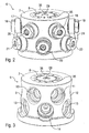
- the valve unit 6 comprises a substantially cylindrical housing consisting of a cylindrical casing shell 7 of plastic material (for example, POM: P oly o xy m ethylene) and also cylindrical housing core 8 is made of stainless steel, wherein the housing core 8 is inserted into the housing shell 7, so that the housing jacket 7 surrounds the housing core 8.
- plastic material for example, POM: P oly o xy m ethylene
- valve seats 9-15 In the housing of the valve unit 6 are a plurality of valve seats 9-15, which are arranged in two valve levels above the other and distributed over the circumference of the housing. In the drawings, only the valve seats 9-15 are shown, but are located on the invisible back of the valve unit six more valve seats, so that the valve unit 6 has a total of eleven valve seats.
- valve seats 13-15 In the lower valve plane in this case are six valve seats 13-15, which are arranged distributed at an angular distance of 60 ° to each other over the circumference of the cylindrical housing of the valve unit 6.
- valve seats 9-12 there are only five valve seats 9-12, which are also distributed with an angular distance of 60 ° to each other over the circumference of the housing.
- valve seats 9-15 are thus arranged in a star shape both in the upper valve plane and in the lower valve plane, the star-shaped arrangements in the two valve planes are offset by 30 ° to each other in order to allow a maximum packing density.
- the valve seat 10 is offset in the upper valve plane by 30 ° relative to the adjacent valve seat 14 in the lower valve plane. This offers the advantage that the two adjacent valve seats 10, 14 do not have to comply with an axial distance, which allows a large packing density.
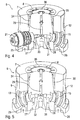
- valves 16-24 are used in the complete state of the valve unit, wherein the valves 16-24 are pneumatically actuated via control lines 25, 26 and control the inlet from a respective coating agent supply line 27, 28 in a central coating agent channel 29 , in particular from the FIGS. 4 and 5 is apparent.
- the individual valves 16-24 each have a valve needle 30, which can be axially displaced by a corresponding pneumatic control via the control line 25, 26 and optionally pressed into a valve seat 31-32 or lifted out of the valve seat 31-32.
- FIG. 1 In the valve position according to FIG.
- valve needle 30 is pressed into the valve seat 32, whereby the valve needle 30 blocks the inlet from the coating agent supply line 27 into the central coating agent channel 29. In this way, by a suitable control of the valves 16-24 of the inlet of one of the coating agent supply lines 27, 28 are released, whereby the desired color is selected.
- valve unit 6 for each of the valve seats 9-15 a leakage line 34, 35, the leakage lines 34, 35 emanating from the associated valve seats 13 and 15 and open in the upper end face of the cylindrical housing core 8.
- annular circumferential collecting channel 36 In this end face of the housing core 8 is an annular circumferential collecting channel 36, in which the individual leakage lines 34, 35 of all valve receptacles 9-15 open.
- the housing core 8 is made of a different material than the housing shell 7. This offers the advantage that the housing core 8 on the one hand and the housing shell 7 on the other hand can be optimized in the selection of materials to their respective function.
- the housing core 8 Important in the choice of material for the housing core 8 is a good material resistance of the media-carrying lines, such as the coating medium supply line 27, 28 of the central coating agent channel 29 and the leakage line 34, 35. In addition, in the choice of material for the housing core 8 is also important that the in the housing core 8 located valve seat 31-32 is not damaged in a cleaning of the housing and also has a sufficient service life otherwise.
- the housing core 8 is therefore made of stainless steel in this embodiment.
- the housing casing 7 consists in this embodiment, made of plastic (such as POM: P oly o xy m ethylene).
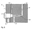
- FIG. 6 shows an alternative embodiment of a valve unit according to the invention 6 ', this embodiment is partially consistent with the embodiment described above, so reference is made to avoid repetition of the above description, with corresponding reference numerals are used, which are provided with an apostrophe ,
- a special feature of this embodiment is that the two housing parts 7 ', 8' are not arranged annularly, but next to each other.
Landscapes
- Spray Control Apparatus (AREA)
- Nozzles (AREA)
- Valve Housings (AREA)
- Electrostatic Spraying Apparatus (AREA)
- Lift Valve (AREA)
Priority Applications (1)
| Application Number | Priority Date | Filing Date | Title |
|---|---|---|---|
| PL11707801T PL2544827T3 (pl) | 2010-03-11 | 2011-03-02 | Zespół zaworowy dla instalacji powlekającej |
Applications Claiming Priority (2)
| Application Number | Priority Date | Filing Date | Title |
|---|---|---|---|
| DE201010011064 DE102010011064A1 (de) | 2010-03-11 | 2010-03-11 | Ventileinheit für eine Beschichtungsanlage |
| PCT/EP2011/001037 WO2011110304A1 (de) | 2010-03-11 | 2011-03-02 | Ventileinheit für eine beschichtungsanlage |
Publications (2)
| Publication Number | Publication Date |
|---|---|
| EP2544827A1 EP2544827A1 (de) | 2013-01-16 |
| EP2544827B1 true EP2544827B1 (de) | 2014-07-30 |
Family
ID=44009933
Family Applications (1)
| Application Number | Title | Priority Date | Filing Date |
|---|---|---|---|
| EP20110707801 Active EP2544827B1 (de) | 2010-03-11 | 2011-03-02 | Ventileinheit für eine beschichtungsanlage |
Country Status (8)
| Country | Link |
|---|---|
| US (1) | US9061310B2 (pl) |
| EP (1) | EP2544827B1 (pl) |
| CN (1) | CN102883819B (pl) |
| DE (1) | DE102010011064A1 (pl) |
| ES (1) | ES2514669T3 (pl) |
| MX (1) | MX2012010307A (pl) |
| PL (1) | PL2544827T3 (pl) |
| WO (1) | WO2011110304A1 (pl) |
Families Citing this family (8)
| Publication number | Priority date | Publication date | Assignee | Title |
|---|---|---|---|---|
| EP2425899B1 (de) * | 2010-09-06 | 2013-08-21 | LacTec GmbH | Farbwechsler |
| ES2481542B1 (es) * | 2013-01-29 | 2015-05-20 | Valver Air Speed, S.L. | Dispositivo adaptador para el cambio de pigmento en aplicadores de pintura |
| EP2987559B1 (en) * | 2014-08-19 | 2016-12-21 | ABB Schweiz AG | Color changer |
| DE102015008659B4 (de) | 2015-07-03 | 2019-06-19 | Dürr Systems Ag | Beschichtungsmittelventil und Rotationszerstäuber |
| DE102015008661A1 (de) | 2015-07-03 | 2017-01-05 | Dürr Systems Ag | Nadelventil |
| DE102015009046A1 (de) * | 2015-07-13 | 2017-01-19 | Dürr Systems Ag | Beschichtungsmittelventil |
| CN107199135B (zh) * | 2017-08-04 | 2022-12-13 | 天津铭捷智能装备有限公司 | 旋杯的内部阀岛 |
| DE102019109208B3 (de) | 2019-04-08 | 2020-10-01 | Dürr Systems Ag | Applikationseinrichtung und entsprechendes Applikationsverfahren |
Family Cites Families (19)
| Publication number | Priority date | Publication date | Assignee | Title |
|---|---|---|---|---|
| US3373762A (en) * | 1965-10-15 | 1968-03-19 | Gen Motors Corp | Multiple fluid delivery system with liquid and gas purging means |
| US3870233A (en) * | 1973-09-12 | 1975-03-11 | Nordson Corp | Color change of electrostatic spray apparatus |
| US4163523A (en) * | 1976-12-15 | 1979-08-07 | Vincent Raymond A | Multicolor paint dispensing system having a pressure responsive color change valve |
| US4592305A (en) * | 1981-01-26 | 1986-06-03 | Ransburg Corporation | Variable low-pressure fluid color change cycle |
| US4567912A (en) * | 1984-07-30 | 1986-02-04 | Acheson Industries, Inc. | Multiple spray nozzles |
| US4714179A (en) * | 1985-03-15 | 1987-12-22 | Ford Motor Company | Positive displacement paint pushout apparatus |
| DE3534269A1 (de) * | 1985-09-26 | 1987-04-02 | Richard C Walther Gmbh & Co Kg | Farbwechselventil |
| DE3709508A1 (de) * | 1987-03-23 | 1988-10-06 | Behr Industrieanlagen | Vorrichtung zum elektrostatischen beschichten von werkstuecken |
| US4846226A (en) * | 1988-08-11 | 1989-07-11 | Binks Manufacturing Company | Color changer |
| GB2224139A (en) * | 1988-10-24 | 1990-04-25 | Philips Electronic Associated | Digital data processing apparatus |
| WO1999036184A1 (fr) | 1998-01-13 | 1999-07-22 | Abb K.K. | Dispositif de revetement de type tete de pulverisation rotative |
| JP2002227799A (ja) * | 2001-02-02 | 2002-08-14 | Honda Motor Co Ltd | 可変流量エゼクタおよび該可変流量エゼクタを備えた燃料電池システム |
| US6682001B2 (en) * | 2002-06-19 | 2004-01-27 | Illinois Tool Works Inc. | Modular color changer |
| DE502004009952D1 (de) * | 2003-07-28 | 2009-10-08 | Duerr Systems Gmbh | Sprühvorrichtung mit Farbwechsler zum serienweisen Beschichten von Werkstücken |
| JP4600808B2 (ja) * | 2004-07-16 | 2010-12-22 | Smc株式会社 | 塗料用切換弁 |
| CN101590456B (zh) | 2005-08-01 | 2011-12-21 | Abb株式会社 | 静电涂敷装置 |
| DE102006022570A1 (de) | 2006-05-15 | 2007-11-29 | Dürr Systems GmbH | Beschichtungseinrichtung und zugehöriges Betriebsverfahren |
| ES2776187T3 (es) * | 2006-12-12 | 2020-07-29 | Duerr Systems Ag | Dosificación ICC |
| EP2425899B1 (de) * | 2010-09-06 | 2013-08-21 | LacTec GmbH | Farbwechsler |
-
2010
- 2010-03-11 DE DE201010011064 patent/DE102010011064A1/de not_active Withdrawn
-
2011
- 2011-03-02 CN CN201180022471.7A patent/CN102883819B/zh active Active
- 2011-03-02 US US13/634,042 patent/US9061310B2/en active Active
- 2011-03-02 MX MX2012010307A patent/MX2012010307A/es active IP Right Grant
- 2011-03-02 EP EP20110707801 patent/EP2544827B1/de active Active
- 2011-03-02 PL PL11707801T patent/PL2544827T3/pl unknown
- 2011-03-02 WO PCT/EP2011/001037 patent/WO2011110304A1/de not_active Ceased
- 2011-03-02 ES ES11707801.4T patent/ES2514669T3/es active Active
Also Published As
| Publication number | Publication date |
|---|---|
| CN102883819B (zh) | 2016-12-21 |
| ES2514669T3 (es) | 2014-10-28 |
| CN102883819A (zh) | 2013-01-16 |
| PL2544827T3 (pl) | 2015-01-30 |
| US20130001326A1 (en) | 2013-01-03 |
| WO2011110304A1 (de) | 2011-09-15 |
| US9061310B2 (en) | 2015-06-23 |
| EP2544827A1 (de) | 2013-01-16 |
| DE102010011064A1 (de) | 2011-09-15 |
| MX2012010307A (es) | 2012-09-28 |
Similar Documents
| Publication | Publication Date | Title |
|---|---|---|
| EP2544827B1 (de) | Ventileinheit für eine beschichtungsanlage | |
| EP2285495B1 (de) | Universalzerstäuber | |
| DE3503384C1 (de) | Spritzpistole für Beschichtungsmaterial | |
| EP3332979B1 (de) | Beschichtungseinrichtung und zugehöriges beschichtungsverfahren | |
| EP0719587A2 (de) | Brausekopf, insbesondere für eine Handbrause | |
| EP2089164B1 (de) | Universalzerstäuber und zugehöriges betriebsverfahren | |
| WO2008068005A1 (de) | Lenkluftring mit einer ringmulde und entsprechender glockenteller | |
| DE102007012878B3 (de) | Zerstäuber zum Zerstäuben eines Beschichtungsmittels | |
| EP2091657B1 (de) | Zentrifuge, insbesondere separator, mit feststoff-austrittsdüsen | |
| DE102015003559A1 (de) | Rotierender Reiniger | |
| DE102006022570A1 (de) | Beschichtungseinrichtung und zugehöriges Betriebsverfahren | |
| EP3887057B1 (de) | Rotationszerstäuber | |
| DE2903148A1 (de) | Vorrichtung fuer die beschichtung von gegenstaenden mit elektrostatisch aufgeladenem staub | |
| DE202010018423U1 (de) | Rotordüse | |
| EP1242190B1 (de) | Hochrotationszerstäuber zur aufbringung von pulverlack | |
| DE4013938A1 (de) | Verfahren und anlage zum serienweisen beschichten von werkstuecken mit leitfaehigem beschichtungsmaterial | |
| DE2925435A1 (de) | Spruehkopf | |
| DE19961202C1 (de) | Innenspritzdüse | |
| DE102005015604A1 (de) | Rotationszerstäuberbauteil, insbesondere Lenkluftring oder Glockenteller | |
| DE3931657A1 (de) | Duesentraeger | |
| EP1452235B1 (de) | Glockenteller und Rotationszerstäuber | |
| EP0724917A1 (de) | Vorrichtung zum Reinigen der Innenwandung eines Weinfasses | |
| DE1577617A1 (de) | Elektrostatische Spritzvorrichtung fuer Farbmaterial u. dgl. | |
| EP0455107B1 (de) | Verfahren und Anlage zum serienweisen Beschichten von Werkstücken mit leitfähigem Beschichtungsmaterial | |
| EP2392406A1 (de) | Spritzdüse zur Zerstäubung einer unter Druck stehenden Flüssigkeit |
Legal Events
| Date | Code | Title | Description |
|---|---|---|---|
| PUAI | Public reference made under article 153(3) epc to a published international application that has entered the european phase |
Free format text: ORIGINAL CODE: 0009012 |
|
| 17P | Request for examination filed |
Effective date: 20120808 |
|
| AK | Designated contracting states |
Kind code of ref document: A1 Designated state(s): AL AT BE BG CH CY CZ DE DK EE ES FI FR GB GR HR HU IE IS IT LI LT LU LV MC MK MT NL NO PL PT RO RS SE SI SK SM TR |
|
| DAX | Request for extension of the european patent (deleted) | ||
| GRAP | Despatch of communication of intention to grant a patent |
Free format text: ORIGINAL CODE: EPIDOSNIGR1 |
|
| INTG | Intention to grant announced |
Effective date: 20140425 |
|
| GRAS | Grant fee paid |
Free format text: ORIGINAL CODE: EPIDOSNIGR3 |
|
| GRAA | (expected) grant |
Free format text: ORIGINAL CODE: 0009210 |
|
| AK | Designated contracting states |
Kind code of ref document: B1 Designated state(s): AL AT BE BG CH CY CZ DE DK EE ES FI FR GB GR HR HU IE IS IT LI LT LU LV MC MK MT NL NO PL PT RO RS SE SI SK SM TR |
|
| REG | Reference to a national code |
Ref country code: GB Ref legal event code: FG4D Free format text: NOT ENGLISH |
|
| REG | Reference to a national code |
Ref country code: CH Ref legal event code: EP |
|
| REG | Reference to a national code |
Ref country code: AT Ref legal event code: REF Ref document number: 679691 Country of ref document: AT Kind code of ref document: T Effective date: 20140815 |
|
| REG | Reference to a national code |
Ref country code: IE Ref legal event code: FG4D Free format text: LANGUAGE OF EP DOCUMENT: GERMAN |
|
| REG | Reference to a national code |
Ref country code: DE Ref legal event code: R096 Ref document number: 502011003884 Country of ref document: DE Effective date: 20140911 |
|
| REG | Reference to a national code |
Ref country code: ES Ref legal event code: FG2A Ref document number: 2514669 Country of ref document: ES Kind code of ref document: T3 Effective date: 20141028 |
|
| REG | Reference to a national code |
Ref country code: NL Ref legal event code: VDEP Effective date: 20140730 |
|
| REG | Reference to a national code |
Ref country code: LT Ref legal event code: MG4D |
|
| REG | Reference to a national code |
Ref country code: SK Ref legal event code: T3 Ref document number: E 17252 Country of ref document: SK |
|
| PG25 | Lapsed in a contracting state [announced via postgrant information from national office to epo] |
Ref country code: FI Free format text: LAPSE BECAUSE OF FAILURE TO SUBMIT A TRANSLATION OF THE DESCRIPTION OR TO PAY THE FEE WITHIN THE PRESCRIBED TIME-LIMIT Effective date: 20140730 Ref country code: PT Free format text: LAPSE BECAUSE OF FAILURE TO SUBMIT A TRANSLATION OF THE DESCRIPTION OR TO PAY THE FEE WITHIN THE PRESCRIBED TIME-LIMIT Effective date: 20141202 Ref country code: GR Free format text: LAPSE BECAUSE OF FAILURE TO SUBMIT A TRANSLATION OF THE DESCRIPTION OR TO PAY THE FEE WITHIN THE PRESCRIBED TIME-LIMIT Effective date: 20141031 Ref country code: SE Free format text: LAPSE BECAUSE OF FAILURE TO SUBMIT A TRANSLATION OF THE DESCRIPTION OR TO PAY THE FEE WITHIN THE PRESCRIBED TIME-LIMIT Effective date: 20140730 Ref country code: BG Free format text: LAPSE BECAUSE OF FAILURE TO SUBMIT A TRANSLATION OF THE DESCRIPTION OR TO PAY THE FEE WITHIN THE PRESCRIBED TIME-LIMIT Effective date: 20141030 Ref country code: NO Free format text: LAPSE BECAUSE OF FAILURE TO SUBMIT A TRANSLATION OF THE DESCRIPTION OR TO PAY THE FEE WITHIN THE PRESCRIBED TIME-LIMIT Effective date: 20141030 Ref country code: LT Free format text: LAPSE BECAUSE OF FAILURE TO SUBMIT A TRANSLATION OF THE DESCRIPTION OR TO PAY THE FEE WITHIN THE PRESCRIBED TIME-LIMIT Effective date: 20140730 |
|
| REG | Reference to a national code |
Ref country code: PL Ref legal event code: T3 |
|
| PG25 | Lapsed in a contracting state [announced via postgrant information from national office to epo] |
Ref country code: RS Free format text: LAPSE BECAUSE OF FAILURE TO SUBMIT A TRANSLATION OF THE DESCRIPTION OR TO PAY THE FEE WITHIN THE PRESCRIBED TIME-LIMIT Effective date: 20140730 Ref country code: IS Free format text: LAPSE BECAUSE OF FAILURE TO SUBMIT A TRANSLATION OF THE DESCRIPTION OR TO PAY THE FEE WITHIN THE PRESCRIBED TIME-LIMIT Effective date: 20141130 Ref country code: CY Free format text: LAPSE BECAUSE OF FAILURE TO SUBMIT A TRANSLATION OF THE DESCRIPTION OR TO PAY THE FEE WITHIN THE PRESCRIBED TIME-LIMIT Effective date: 20140730 Ref country code: NL Free format text: LAPSE BECAUSE OF FAILURE TO SUBMIT A TRANSLATION OF THE DESCRIPTION OR TO PAY THE FEE WITHIN THE PRESCRIBED TIME-LIMIT Effective date: 20140730 Ref country code: HR Free format text: LAPSE BECAUSE OF FAILURE TO SUBMIT A TRANSLATION OF THE DESCRIPTION OR TO PAY THE FEE WITHIN THE PRESCRIBED TIME-LIMIT Effective date: 20140730 Ref country code: LV Free format text: LAPSE BECAUSE OF FAILURE TO SUBMIT A TRANSLATION OF THE DESCRIPTION OR TO PAY THE FEE WITHIN THE PRESCRIBED TIME-LIMIT Effective date: 20140730 |
|
| PG25 | Lapsed in a contracting state [announced via postgrant information from national office to epo] |
Ref country code: DK Free format text: LAPSE BECAUSE OF FAILURE TO SUBMIT A TRANSLATION OF THE DESCRIPTION OR TO PAY THE FEE WITHIN THE PRESCRIBED TIME-LIMIT Effective date: 20140730 Ref country code: CZ Free format text: LAPSE BECAUSE OF FAILURE TO SUBMIT A TRANSLATION OF THE DESCRIPTION OR TO PAY THE FEE WITHIN THE PRESCRIBED TIME-LIMIT Effective date: 20140730 Ref country code: RO Free format text: LAPSE BECAUSE OF FAILURE TO SUBMIT A TRANSLATION OF THE DESCRIPTION OR TO PAY THE FEE WITHIN THE PRESCRIBED TIME-LIMIT Effective date: 20140730 Ref country code: EE Free format text: LAPSE BECAUSE OF FAILURE TO SUBMIT A TRANSLATION OF THE DESCRIPTION OR TO PAY THE FEE WITHIN THE PRESCRIBED TIME-LIMIT Effective date: 20140730 |
|
| REG | Reference to a national code |
Ref country code: DE Ref legal event code: R097 Ref document number: 502011003884 Country of ref document: DE |
|
| PLBE | No opposition filed within time limit |
Free format text: ORIGINAL CODE: 0009261 |
|
| STAA | Information on the status of an ep patent application or granted ep patent |
Free format text: STATUS: NO OPPOSITION FILED WITHIN TIME LIMIT |
|
| 26N | No opposition filed |
Effective date: 20150504 |
|
| PG25 | Lapsed in a contracting state [announced via postgrant information from national office to epo] |
Ref country code: LU Free format text: LAPSE BECAUSE OF FAILURE TO SUBMIT A TRANSLATION OF THE DESCRIPTION OR TO PAY THE FEE WITHIN THE PRESCRIBED TIME-LIMIT Effective date: 20150302 Ref country code: MC Free format text: LAPSE BECAUSE OF FAILURE TO SUBMIT A TRANSLATION OF THE DESCRIPTION OR TO PAY THE FEE WITHIN THE PRESCRIBED TIME-LIMIT Effective date: 20140730 |
|
| REG | Reference to a national code |
Ref country code: CH Ref legal event code: PL |
|
| PG25 | Lapsed in a contracting state [announced via postgrant information from national office to epo] |
Ref country code: SI Free format text: LAPSE BECAUSE OF FAILURE TO SUBMIT A TRANSLATION OF THE DESCRIPTION OR TO PAY THE FEE WITHIN THE PRESCRIBED TIME-LIMIT Effective date: 20140730 |
|
| REG | Reference to a national code |
Ref country code: HU Ref legal event code: AG4A Ref document number: E024223 Country of ref document: HU |
|
| REG | Reference to a national code |
Ref country code: IE Ref legal event code: MM4A |
|
| PG25 | Lapsed in a contracting state [announced via postgrant information from national office to epo] |
Ref country code: LI Free format text: LAPSE BECAUSE OF NON-PAYMENT OF DUE FEES Effective date: 20150331 Ref country code: CH Free format text: LAPSE BECAUSE OF NON-PAYMENT OF DUE FEES Effective date: 20150331 Ref country code: IE Free format text: LAPSE BECAUSE OF NON-PAYMENT OF DUE FEES Effective date: 20150302 |
|
| REG | Reference to a national code |
Ref country code: FR Ref legal event code: PLFP Year of fee payment: 6 |
|
| REG | Reference to a national code |
Ref country code: DE Ref legal event code: R082 Ref document number: 502011003884 Country of ref document: DE Representative=s name: V. BEZOLD & PARTNER PATENTANWAELTE - PARTG MBB, DE Ref country code: DE Ref legal event code: R081 Ref document number: 502011003884 Country of ref document: DE Owner name: DUERR SYSTEMS AG, DE Free format text: FORMER OWNER: DUERR SYSTEMS GMBH, 74321 BIETIGHEIM-BISSINGEN, DE |
|
| PG25 | Lapsed in a contracting state [announced via postgrant information from national office to epo] |
Ref country code: MT Free format text: LAPSE BECAUSE OF FAILURE TO SUBMIT A TRANSLATION OF THE DESCRIPTION OR TO PAY THE FEE WITHIN THE PRESCRIBED TIME-LIMIT Effective date: 20140730 |
|
| REG | Reference to a national code |
Ref country code: DE Ref legal event code: R082 Ref document number: 502011003884 Country of ref document: DE Representative=s name: V. BEZOLD & PARTNER PATENTANWAELTE - PARTG MBB, DE Ref country code: DE Ref legal event code: R081 Ref document number: 502011003884 Country of ref document: DE Owner name: DUERR SYSTEMS AG, DE Free format text: FORMER OWNER: DUERR SYSTEMS AG, 74321 BIETIGHEIM-BISSINGEN, DE |
|
| REG | Reference to a national code |
Ref country code: FR Ref legal event code: PLFP Year of fee payment: 7 |
|
| REG | Reference to a national code |
Ref country code: AT Ref legal event code: MM01 Ref document number: 679691 Country of ref document: AT Kind code of ref document: T Effective date: 20160302 |
|
| PG25 | Lapsed in a contracting state [announced via postgrant information from national office to epo] |
Ref country code: SM Free format text: LAPSE BECAUSE OF FAILURE TO SUBMIT A TRANSLATION OF THE DESCRIPTION OR TO PAY THE FEE WITHIN THE PRESCRIBED TIME-LIMIT Effective date: 20140730 |
|
| PG25 | Lapsed in a contracting state [announced via postgrant information from national office to epo] |
Ref country code: BE Free format text: LAPSE BECAUSE OF NON-PAYMENT OF DUE FEES Effective date: 20150331 |
|
| PG25 | Lapsed in a contracting state [announced via postgrant information from national office to epo] |
Ref country code: AT Free format text: LAPSE BECAUSE OF NON-PAYMENT OF DUE FEES Effective date: 20160302 Ref country code: TR Free format text: LAPSE BECAUSE OF FAILURE TO SUBMIT A TRANSLATION OF THE DESCRIPTION OR TO PAY THE FEE WITHIN THE PRESCRIBED TIME-LIMIT Effective date: 20140730 |
|
| REG | Reference to a national code |
Ref country code: FR Ref legal event code: PLFP Year of fee payment: 8 |
|
| REG | Reference to a national code |
Ref country code: HU Ref legal event code: HC9C Owner name: DUERR SYSTEMS GMBH, DE |
|
| PG25 | Lapsed in a contracting state [announced via postgrant information from national office to epo] |
Ref country code: MK Free format text: LAPSE BECAUSE OF FAILURE TO SUBMIT A TRANSLATION OF THE DESCRIPTION OR TO PAY THE FEE WITHIN THE PRESCRIBED TIME-LIMIT Effective date: 20140730 |
|
| PG25 | Lapsed in a contracting state [announced via postgrant information from national office to epo] |
Ref country code: AL Free format text: LAPSE BECAUSE OF FAILURE TO SUBMIT A TRANSLATION OF THE DESCRIPTION OR TO PAY THE FEE WITHIN THE PRESCRIBED TIME-LIMIT Effective date: 20140730 |
|
| P01 | Opt-out of the competence of the unified patent court (upc) registered |
Effective date: 20230512 |
|
| PGFP | Annual fee paid to national office [announced via postgrant information from national office to epo] |
Ref country code: DE Payment date: 20250319 Year of fee payment: 15 |
|
| PGFP | Annual fee paid to national office [announced via postgrant information from national office to epo] |
Ref country code: HU Payment date: 20250321 Year of fee payment: 15 |
|
| PGFP | Annual fee paid to national office [announced via postgrant information from national office to epo] |
Ref country code: FR Payment date: 20250325 Year of fee payment: 15 Ref country code: PL Payment date: 20250221 Year of fee payment: 15 |
|
| PGFP | Annual fee paid to national office [announced via postgrant information from national office to epo] |
Ref country code: IT Payment date: 20250325 Year of fee payment: 15 Ref country code: SK Payment date: 20250227 Year of fee payment: 15 Ref country code: GB Payment date: 20250321 Year of fee payment: 15 |
|
| PGFP | Annual fee paid to national office [announced via postgrant information from national office to epo] |
Ref country code: ES Payment date: 20250425 Year of fee payment: 15 |