EP2544613B1 - Plaque d'osteosynthese articulee - Google Patents
Plaque d'osteosynthese articulee Download PDFInfo
- Publication number
- EP2544613B1 EP2544613B1 EP11714351.1A EP11714351A EP2544613B1 EP 2544613 B1 EP2544613 B1 EP 2544613B1 EP 11714351 A EP11714351 A EP 11714351A EP 2544613 B1 EP2544613 B1 EP 2544613B1
- Authority
- EP
- European Patent Office
- Prior art keywords
- diaphyseal
- epiphyseal
- distal
- slot
- screw
- Prior art date
- Legal status (The legal status is an assumption and is not a legal conclusion. Google has not performed a legal analysis and makes no representation as to the accuracy of the status listed.)
- Active
Links
Images
Classifications
-
- A—HUMAN NECESSITIES
- A61—MEDICAL OR VETERINARY SCIENCE; HYGIENE
- A61B—DIAGNOSIS; SURGERY; IDENTIFICATION
- A61B17/00—Surgical instruments, devices or methods
- A61B17/56—Surgical instruments or methods for treatment of bones or joints; Devices specially adapted therefor
- A61B17/58—Surgical instruments or methods for treatment of bones or joints; Devices specially adapted therefor for osteosynthesis, e.g. bone plates, screws or setting implements
- A61B17/68—Internal fixation devices, including fasteners and spinal fixators, even if a part thereof projects from the skin
- A61B17/80—Cortical plates, i.e. bone plates; Instruments for holding or positioning cortical plates, or for compressing bones attached to cortical plates
-
- A—HUMAN NECESSITIES
- A61—MEDICAL OR VETERINARY SCIENCE; HYGIENE
- A61B—DIAGNOSIS; SURGERY; IDENTIFICATION
- A61B17/00—Surgical instruments, devices or methods
- A61B17/56—Surgical instruments or methods for treatment of bones or joints; Devices specially adapted therefor
- A61B17/58—Surgical instruments or methods for treatment of bones or joints; Devices specially adapted therefor for osteosynthesis, e.g. bone plates, screws or setting implements
- A61B17/68—Internal fixation devices, including fasteners and spinal fixators, even if a part thereof projects from the skin
- A61B17/80—Cortical plates, i.e. bone plates; Instruments for holding or positioning cortical plates, or for compressing bones attached to cortical plates
- A61B17/8061—Cortical plates, i.e. bone plates; Instruments for holding or positioning cortical plates, or for compressing bones attached to cortical plates specially adapted for particular bones
Definitions
- the present invention relates to an osteosynthesis plate for reducing a distal fracture of a bone of the radius type, the plate comprising an enlarged epiphyseal portion in the form of a pallet provided with fixing holes for anchor screws and an elongated diaphyseal part. also provided with holes for anchoring screws.
- epiphyseal part is meant the part situated on the distal side of the fractured bone or epiphysis, and by diaphyseal part, the part situated on the proximal or diaphysis side of the body of the bone concerned.
- the invention finds a particularly important, although not exclusive, application in the field of reducing and / or temporarily fixing a fractured part of a radius to the rest of the bone, the plate possibly being removable after consolidation. of the fracture.
- a plate will also allow faster rehabilitation of the joint by soliciting it, to avoid subsequent phenomena such as osteoarthritis.
- the object of the present invention is to provide an osteosynthesis plate better than those previously known to the requirements of the practice, in particular in that it allows to reorient the elongated diaphyseal portion despite the initial fixation of the epiphyseal part during the operation, while having a small footprint in thickness, and excellent fixation of the epiphyseal part on the two parts of bone to reduce.
- the embodiment of the invention more particularly described not only proposes to orient between them, modifiable way in the plane of the elongated diaphyseal part, the two parts namely the epiphyseal part and the diaphyseal part, but this proposing a simple and solid fixation of the epiphyseal part.
- Such a possibility of orientation allows adjustment of the positioning of the diaphyseal portion of the plate, while allowing a longitudinal movement through an oblong hole, then a lock in the correct position, while the two parts of bone are reduced and firmly attached to each other.
- the invention is of course usable on any type of elongate or long bone end fracture, or osteosynthesis, and not only on one end of the radius.
- the present invention essentially provides an osteosynthesis plate as described in the appended claims.
- the diaphyseal part of the plate can be oriented to be adjustably fixed relative to the distal portion in the form of a pallet, this makes it possible to avoid a lateral protrusion with respect to the body of the bone, which would have caused an inconvenience for the patient.
- the epiphyseal portion is arranged to be rigidly attached to the two bone parts.
- the attachment portions are thus arranged to be in contact by their lower faces directly with the bone to be reduced.
- the angle given between the planes of the diaphyseal and epiphyseal parts makes it possible to better adapt to the configuration of the bone. It is for example a few degrees for example 5 to 15 °, and preferably between 8 and 10 °.
- the joining ends comprise identical toothed surfaces facing each other, an existing rotational mobility when they are separated from one another, a blocking being obtained when they are close together and in contact with each other, so that the notches of the two surfaces facing each other penetrate each other.
- the screws used are arranged to lock at the end of the race to prevent migration in a manner known per se.
- junction ends bearing the nipple By one of the junction ends bearing the nipple is meant in the mode more particularly described an end of the epiphyseal part, and the other junction end provided with light an end of the diaphyseal part.
- the plate 1 comprises an enlarged epiphyseal portion 4 in the form of a substantially trapezoidal pallet, for example provided with a central recessed area 5 at the base of the epiphyseal part.
- the epiphyseal part 4 is provided with fixing holes 6 by first anchoring screws 7, in a manner known per se.
- It also comprises an elongate diaphyseal portion 8, for example substantially rectangular, provided with second fixing holes 9 by second anchoring screw 10.
- the plate 1 further comprises a system 11 of articulation between the two parts of amplitude ⁇ 15 °.
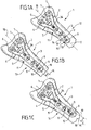
- Figures 1A to 1C show the epiphyseal and diaphyseal parts when in central alignment position (position 12 - Figure 1A ), having an angle of 5 ° (position 13 - Figure 1B ) or 10 ° (position 14 - figure 1C )).
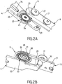
- FIGS. 2A and 2B show more precisely the articulation system 11 of the figure 1 , between the ends 20 and 21, respectively of the epiphyseal portions 4 and diaphyseal 8. Each end 20 and 21 is refined in its respective distal portion 22, 23 to connect without excess thickness.
- the end 20 comprises a junction 24, notched, circular, comprising on both sides stops 25 of the rotating end.
- the other end 21 opposite also comprises a junction surface 26 circular notched facing, arranged to rotate relative to the toothed surface 24 facing a central axis.
- a screw 27 comes to press the two end portions 20 and 21 one on the other and lock the system in the selected angular position.
- the end 21 also has two stops 28 abutting with the stops 25 of the end of the epiphyseal part, when the extreme angles of + 15 ° for example or -15 ° are reached.
- the end 20 further includes a nipple 29 of the lower part, which is here in this embodiment, the epiphyseal portion 4 arranged to fit into an arcuate slot 30 belonging to the upper part 21.
- a locking screw 31 completes these fastening means from one end to the other, by screwing into the stud opposite when fixing through the light 30, the head of the screw a collar is locked on top of the portion 21 when the two ends are contiguous to one another and locked in rotation.
- the screws 27 and 31 are arranged to lock at the end of stroke to prevent migration, in a manner known per se.
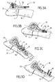
- step 32 - figure 3A First (step 32 - figure 3A ) is placed in the eye, the plate 1 on the epiphyseal portion 33 of the bone, which is particularly useful in case of communitive fracture F.
- the epiphyseal part 4 also comprises an elongate hole 34, which allows the longitudinal adjustment in a manner known per se.
- step 35 figure 3B the fracture F is reduced by means of the plate, bringing the fractured portion 33 closer to the rest of the bone 36. But at this stage, the longitudinal axis 18 of the laid plate passing through the center 36 'of the notched circular junction surface 24.
- step 37 - figure 3C we come to affix (step 37 - figure 3C ) the diaphyseal portion 8 by adjusting the desired angle ⁇ to correct the axis of this part of the plate relative to the bone.
- step 38 - 3D figure the longitudinal position is refined (step 38 - 3D figure ) thanks to the oblong hole 34 and the screw 39 before definitively fixing the diaphyseal part 8 by the screws 40.
- the epiphyseal part is directly attached, on the one hand to the fractured part of bone 33 and on the other hand to the remainder of the bone 36, independently of the diaphyseal orientable part which terminates the fixation in length on the bone.
- Bone 36 autorigidified by the double screw system 27 and 31.
- the length of the axis of rotation of the screw 27 is 5 to 10 mm, the depth of the notches of the order of 0.2 mm, the number of notches being between 50 and 100 , for a thinned portion length of 10 to 15 mm.
- the present invention is not limited to the embodiment more particularly described. On the contrary, it embraces all the variants and in particular those where the angles are not ⁇ 15 ° but ⁇ 10 ° and / or ⁇ 20 °, that in which the epiphyseal part and the diaphyseal part are different from those described and / or are in different materials, those where there are two nipples screwed to screws of two lights respectively located in the other end with which they cooperate slidingly, namely a nipple on the ephiphyseal part and a nipple on the diaphyseal part, and a light on the parts facing each other, the nipples (and therefore the lights) being located on either side, for example symmetrically of the axis of rotation of the hinge and locking with fixing screws of the nipple through the corresponding light.
Landscapes
- Health & Medical Sciences (AREA)
- Orthopedic Medicine & Surgery (AREA)
- Surgery (AREA)
- Life Sciences & Earth Sciences (AREA)
- Heart & Thoracic Surgery (AREA)
- Nuclear Medicine, Radiotherapy & Molecular Imaging (AREA)
- Engineering & Computer Science (AREA)
- Biomedical Technology (AREA)
- Neurology (AREA)
- Medical Informatics (AREA)
- Molecular Biology (AREA)
- Animal Behavior & Ethology (AREA)
- General Health & Medical Sciences (AREA)
- Public Health (AREA)
- Veterinary Medicine (AREA)
- Surgical Instruments (AREA)
Description
- La présente invention concerne une plaque d'ostéosynthèse pour réduction d'une fracture distale d'un os du type radius, la plaque comportant une partie épiphysaire élargie en forme de palette munie de trous de fixation pour vis d'ancrage et une partie diaphysaire allongée également munie de trous pour vis d'ancrage.
- Par partie épiphysaire on entend la partie située du côté distal de l'os ou épiphyse fracturée, et par partie diaphysaire, la partie située du côté proximal ou diaphyse du corps de l'os concerné.
- L'invention trouve une application particulièrement importante bien que non exclusive dans le domaine de la réduction et/ou de la fixation provisoire d'une partie fracturée d'un radius sur le reste de l'os, la plaque pouvant éventuellement être retirée après consolidation de la fracture. Une telle plaque va également permettre la rééducation plus rapide de l'articulation en la sollicitant, pour éviter des phénomènes ultérieurs tels que l'arthrose.
- On connaît déjà, dans le cas de fractures distales du radius, des plaques permettant un positionnement en longueur grâce à un trou oblong. De telles plaques, qui ramènent le fragment distal à la bonne distance et le fixent en réglant en longueur la plaque avant de la verrouiller dans la diaphyse, n'autorisent cependant aucun ajustement latéral.
- Or, il se trouve que dans certains cas, il est nécessaire de fixer d'abord les fragments distaux du radius sur la plaque. Ce n'est qu'ensuite que la fracture va être réduite sur la diaphyse.
- On ne peut cependant jamais être certain de l'orientation de la plaque, qui n'est dès lors pas toujours dans l'axe du radius.
- Il peut alors y avoir un dépassement côté proximal de la partie diaphysaire allongée et donc gêne pour le patient. Le chirurgien ne peut pas corriger ce léger défaut de positionnement latéral sans repositionner la partie épiphysaire ce qui va nécessiter de repercer à côté des premiers trous pour se décaler. En pratique ce n'est pas possible car les trous sont alors trop proches.
- On connaît également (
WO 2004/045389 ouUS 2009/0275947 ) des plaques munies de moyens pivotant permettant d'ajuster en rotation la partie diaphysaire par rapport à la partie épiphysaire. - Mais de tels moyens sont soit trop compliqués, soit peu solides et/ou trop encombrants en hauteur.
- L'objet de la présente invention est de proposer une plaque d'ostéosynthèse répondant mieux que celles antérieurement connues aux exigences de la pratique, notamment en ce qu'elle permet de réorienter la partie diaphysaire allongée malgré la fixation initiale de la partie épiphysaire lors de l'opération, tout en présentant un encombrement faible en épaisseur, et une excellente fixation de la partie épiphysaire sur les deux parties d'os à réduire.
- Pour ce faire, le mode de réalisation de l'invention plus particulièrement décrit, non seulement se propose d'orienter entre elles, de façon modifiable dans le plan de la partie diaphysaire allongée, les deux parties à savoir la partie épiphysaire et la partie diaphysaire, mais ce en proposant une fixation simple et solide de la partie épiphysaire.
- Une telle possibilité d'orientation permet un réglage du positionnement de la partie diaphysaire de la plaque, tout en autorisant un déplacement longitudinal par le biais d'un trou oblong, puis un verrouillage dans la bonne position, alors que les deux parties d'os sont réduites et fixées solidement l'une à l'autre.
- L'invention est bien entendu utilisable sur tout type de fracture d'extrémité d'os allongé ou long, ou d'ostéosynthèse, et non pas seulement sur une extrémité de radius.
- Dans ce but la présente invention propose essentiellement une plaque d'ostéosynthèse telle que décrite dans les revendications annexées.
- La partie diaphysaire de la plaque pouvant s'orienter pour être fixée de façon réglable par rapport à la partie distale en forme de palette, cela permet d'éviter un dépassement latéral par rapport au corps de l'os, dépassement qui aurait occasionné une gêne pour le patient.
- La partie épiphysaire est agencée pour être rigidement fixée sur les deux parties d'os.
- Les portions de fixation sont ainsi agencées pour être en contact par leurs faces inférieures directement avec l'os à réduire.
- De la sorte, en étant fixée par le biais des vis d'ancrage mettant la partie épiphysaire directement en pression entre la tête des vis et l'os, une fixation d'une grande solidité entre les deux parties d'os est obtenue.
- Dans des modes de réalisation avantageux, on a de plus recours à l'une et/ou à l'autre des dispositions suivantes :
- la plaque comporte des moyens de verrouillage dans la position angulaire choisie, rendant l'articulation blocable dans cette position.
- Par articulation blocable, on entend une articulation permettant un réglage en orientation, qui une fois ladite orientation choisie, permet ensuite de bloquer rigidement les deux parties l'une par rapport à l'autre ;
- les moyens de verrouillage de la partie épiphysaire avec la partie diaphysaire comprennent des moyens de blocage surfaciques espacés longitudinalement avec un système de blocage réglable par vis de blocage. Par moyens surfaciques il faut entendre des moyens de jonction et/ou de coopération de l'un par rapport à l'autre par l'intermédiaire d'une portion de contact régulière ou non s'étendant sur une surface par exemple de 0,5 cm2 ou plus ;
- pour former le système de blocage réglable l'une des extrémités de jonction entre parties diaphysaire et épiphysaire de la plaque comporte un téton en vis à vis d'une lumière située dans l'autre extrémité de jonction complémentaire entre partie épiphysaire et diaphysaire, avec laquelle il coopère à glissement, et une vis de fixation du téton sur l'autre extrémité au travers de ladite lumière ;
- la partie diaphysaire est sensiblement allongée dans un premier plan et la partie épiphysaire est située principalement dans un deuxième plan incliné par rapport au plan de ladite partie diaphysaire.
- L'angle donné entre les plans des parties diaphysaire et épiphysaire permet de mieux s'adapter à la configuration de l'os. Il est par exemple de quelques degrés par exemple 5 à 15°, et avantageusement entre 8 et 10°.
- Le fait d'être principalement situé dans un plan incliné permet notamment à la jonction entre plaques d'être droite ;
- les deux valeurs d'angles déterminées dans le plan diaphysaire sont +15° et -15° par rapport à la position d'alignement central, autorisant toutes les positions angulaires entre les deux valeurs de façon continue ou quasi-continue. Les valeurs extrêmes peuvent être également inférieures, par exemple +10° et -10° ;
- les parties épiphysaires et diaphysaires sont amovibles l'une par rapport à l'autre. En d'autres termes elles ne sont pas structurellement solidaires, mais séparées l'une de l'autre avant montage et fixation de l'une sur l'autre ;
- pour former les moyens surfaciques de blocage, chacune des parties épiphysaire et diaphysaire comprend une extrémité de jonction avec l'autre partie présentant une surface de coopération de l'une avec l'autre, et des moyens de blocage en rotation desdites extrémités l'une par rapport à l'autre ;
- les extrémités de jonction en vis à vis sont amincies et superposées pour ne pas présenter de surépaisseur par rapport au reste de la partie diaphysaire une fois jointes ;
- les moyens surfaciques de blocage comprennent deux surfaces crantées en vis à vis chacune respectivement solidaires d'une extrémité de jonction, propres à tourner l'une par rapport à l'autre à distance et à se bloquer l'une en contact de l'autre et une vis de blocage de l'une sur l'autre.
- En d'autres termes les extrémités de jonction comprennent des surfaces crantées identiques en regard l'une de l'autre, une mobilité en rotation existant quand elles sont écartées l'une de l'autre, un blocage étant par contre obtenu quand elles sont rapprochées et en contact l'une avec l'autre, de sorte que les crans des deux surfaces en vis à vis se pénètrent les uns les autres.
- Le blocage se fait par l'intermédiaire d'une vis de façon connue ;
- l'une des extrémités de jonction comporte un téton en vis à vis d'une lumière située dans l'autre extrémité de jonction avec laquelle il coopère à glissement, et une vis de fixation du téton sur l'autre extrémité au travers de ladite lumière.
- Les vis utilisées sont agencées pour se verrouiller en fin de course pour éviter toute migration de façon connue en elle-même.
- Par l'une des extrémités de jonction porteuses du téton, on entend dans le mode plus particulièrement décrit une extrémité de la partie épiphysaire, et par l'autre extrémité de jonction munie de la lumière une extrémité de la partie diaphysaire.
- Mais cela peut être l'inverse, la lumière étant sur la partie diaphysaire et le téton sur la partie épiphysaire.
- La présente invention sera mieux comprise à la lecture de la description qui suit d'un mode de réalisation donné ci-après à titre d'exemple non limitatif.
- L'invention se réfère aux figures qui l'accompagnent dans lesquelles :
- Les
figures 1A, 1B et 1C montrent un mode de réalisation de plaque articulée selon l'invention dans trois positions angulaires respectives, respectivement à 0 degré, à 5 degrés et à 10 degrés par rapport à une position d'alignement central. - Les
figures 2A et 2B montrent en perspective axionométrique, respectivement par le dessus et par le dessous, les extrémités de jonction entre les parties faisant apparaître les moyens de blocage en rotation selon le mode de réalisation de l'invention plus particulièrement décrit ici. - Les
figures 3A à 3D donnent les étapes successives de mise en place d'une plaque d'ostéosynthèse selon le mode de réalisation de lafigure 1 . - Les
figures 1 montrent une plaque d'ostéosynthèse 1 pour réduction d'une fracture distale 2 du radius 3. - La plaque 1 comporte une partie épiphysaire élargie 4 en forme de palette sensiblement trapézoïdale par exemple munie d'une zone centrale évidée 5 à la base de la partie épiphysaire.
- La partie épiphysaire 4 est munie de trous de fixation 6 par des premières vis d'ancrage 7, de façon connue en elle-même.
- Elle comporte également une partie diaphysaire 8 allongée, par exemple sensiblement rectangulaire, munie de seconds trous 9 de fixation par secondes vis d'ancrage 10.
- Selon le mode de réalisation plus particulièrement décrit ici, la plaque 1 comporte de plus un système 11 d'articulation entre les deux parties d'amplitude ± 15°.
- Plus précisément les
figures 1A à 1C montrent les parties épiphysaire et diaphysaire lorsqu'elles sont en position d'alignement central (position 12 -figure 1A ), présentant un angle de 5° (position 13 -figure 1B ) ou de 10° (position 14 -figure 1C )). - On voit que dans le cas de l'alignement central (
figure 1A ), le bord externe 15 de l'extrémité de la partie diaphysaire 8 est très proche du bord 16 de la partie proximale 17 de l'os ce qui peut occasionner une gêne. Dans la position 13 (figure 1B ), l'angle α entre l'axe ou ligne 18 d'alignement central, avec l'axe 19 de la partie diaphysaire est de 5°, et de 10° dans la position 14 (figure 1C ). - Les
figures 2A et 2B montrent plus précisément le système d'articulation 11 de lafigure 1 , entre les extrémités 20 et 21, respectivement des parties épiphysaire 4 et diaphysaire 8. Chaque extrémité 20 et 21 est affinée dans sa partie distale respective 22, 23 pour se raccorder sans surépaisseur. - Plus précisément l'extrémité 20 comporte une surface de coopération de jonction 24, crantée, circulaire, comprenant de part et d'autre des butées 25 de l'extrémité en rotation.
- L'autre extrémité 21 en vis à vis comprend également une surface de jonction 26 circulaire crantée en regard, agencée pour tourner par rapport à la surface crantée 24 en vis à vis autour d'un axe central.
- Une vis 27 vient plaquer les deux parties d'extrémité 20 et 21 l'une sur l'autre et verrouiller le système dans la position angulaire choisie.
- L'extrémité 21 comporte également deux butées 28 venant en butée avec les butées 25 de l'extrémité de la partie épiphysaire, lorsque les angles extrêmes de +15° par exemple ou -15° sont atteints.
- L'extrémité 20 comporte par ailleurs un téton 29 de la partie inférieure, qui est ici dans ce mode de réalisation, la partie épiphysaire 4 agencée pour venir s'encastrer dans une lumière 30 en arc de cercle appartenant à la partie supérieure 21.
- Une vis de verrouillage 31 vient compléter ces moyens de fixation d'une extrémité sur l'autre, en se vissant dans le téton en vis à vis lors de la fixation au travers de la lumière 30, de la tête de
la vis une collerette vient se bloquer sur le dessus de la partie 21 lorsque les deux extrémités sont accolées l'une à l'autre et verrouillées en rotation. - Les vis 27 et 31 sont agencées pour se verrouiller en fin de course pour éviter toute migration, de façon connue en elle-même.
- On va maintenant décrire en référence à la
figure 3 la mise en place d'une plaque selon le mode de réalisation plus particulièrement décrit ici. - Dans la suite on utilisera les mêmes numéros de référence pour désigner les mêmes éléments que dans les figures décrites ci-avant.
- Tout d'abord (étape 32 -
figure 3A ) on met en place à l'oeil, la plaque 1 sur la partie épiphysaire 33 de l'os, ce qui est particulièrement utile en cas de fracture communitive F. - Pour se faire on fixe la partie épiphysaire 4 par des vis d'ancrage 7, en réglant au mieux.
- Comme représenté sur la
figure 3A la partie épiphysaire 4 comporte également un trou oblong 34, qui permet le réglage longitudinal de façon connue en elle-même. - Puis (étape 35
figure 3B ) on réduit la fracture F à l'aide de la plaque, en rapprochant la partie fracturée 33 du reste de l'os 36. Mais à ce stade on ne contrôle pas vraiment l'axe longitudinal 18 de la plaque posée qui passe par le centre 36' de la surface circulaire crantée de jonction 24. - En effet seule la partie épiphysaire, comme indiqué sur la
figure 3B est placée pour l'instant sur l'os. - Puis on vient apposer (étape 37 -
figure 3C ) la partie diaphysaire 8 en réglant l'angle α souhaité, pour corriger l'axe de cette partie de la plaque par rapport à l'os. - Une fois correctement placée on verrouille, par l'intermédiaire des deux vis de verrouillage 27 et 31 comme décrit ci-avant.
- Enfin on affine la position longitudinale (étape 38 -
figure 3D ) grâce au trou oblong 34 et à la vis 39 avant de fixer définitivement la partie diaphysaire 8 par les vis 40. - De la sorte, la partie épiphysaire est directement fixée, d'une part à la partie fracturée d'os 33 et d'autre part au reste de l'os 36, indépendamment de la partie diaphysaire orientable qui termine la fixation en longueur sur l'os 36, de façon autorigidifiée par le système de double vis 27 et 31.
- A titre d'exemple non limitatif la longueur de l'axe de rotation de la vis 27 est de 5 à 10 mm, la profondeur des crans de l'ordre de 0,2 mm, le nombre de crans étant compris entre 50 et 100, pour une longueur de partie amincie de 10 à 15 mm.
- Comme il va de soi et comme il résulte également de ce qui précède, la présente invention n'est pas limitée au mode de réalisation plus particulièrement décrit. Elle en embrasse au contraire toutes les variantes et notamment celles où les angles ne sont pas de ±15° mais ±10° et/ou ±20°, celle où la partie épiphysaire et la partie diaphysaire sont différentes de celles décrites et/ou sont en matériaux différents, celles où il existe deux tétons en vis à vis de deux lumières respectivement situées dans l'autre extrémité avec lesquels ils coopèrent à glissement, à savoir un téton sur la partie éphiphysaire et un téton sur la partie diaphysaire, et une lumière sur les parties en vis à vis, les tétons (et donc les lumières) étant située de part et d'autre, par exemple symétriquement de l'axe de rotation de l'articulation et se verrouillant avec des vis de fixation du téton au travers de la lumière correspondante.
Claims (12)
- Système pour réduction d'une fracture distale (2) d'os (3) allongé, entre une partie fracturée distale (33) de l'os et une partie proximale (36), comprenant :une plaque (1) d'ostéosynthèse comportant une partie épiphysaire (4) élargie en forme de palette munie de premiers trous (6) de fixation pour premières vis d'ancrage (7) et une partie diaphysaire (8) allongée munie de seconds trous (9) de fixation pour secondes vis d'ancrage (10), ladite plaque comportant une articulation entre la partie épiphysaire et la partie diaphysaire dans le plan de ladite partie diaphysaire entre deux valeurs d'angle déterminées par rapport à une position d'alignement central (18); etune troisième vis d'ancrage (39) ;la partie épiphysaire (4) comprenant d'un côté une première portion de fixation formant une extrémité élargie distale munie desdits premiers trous (6) de fixation sur la partie distale (33) de l'os fracturé, et de l'autre côté une deuxième portion de fixation formant une extrémité rétrécie proximale,caractérisé en ce que ladite extrémité rétrécie proximale est munie d'un premier trou oblong (34) de fixation sur la partie proximale (36) de l'os destiné à recevoir la troisième vis d'ancrage (39), pour fixer la partie épiphysaire (4) à chacune des parties fracturées distale (33) et proximale (36) de l'os (3) fracturé de sorte que la partie épiphysaire est inamovible vis-à-vis de l'os, le premier trou oblong (34) étant tel que les parties distale (33) et proximale (36) de l'os fracturé sont mobiles l'une par rapport à l'autre avant l'insertion de la troisième vis d'ancrage (39) dans la partie distale (33), et immobiles l'une par rapport à l'autre après l'insertion de la troisième vis d'ancrage (39) dans la partie distale (33),et en ce que l'extrémité rétrécie de la partie épiphysaire comprend en outre une vis de blocage (27) et une vis de fixation (31), la vis de blocage (27) définissant un axe de rotation entre les parties épiphysaire et diaphysaire et étant adaptée pour verrouiller la partie épiphysaire (4) avec la partie diaphysaire (8), la vis de fixation (31) étant agencée pour joindre la partie épiphysaire (4) à la partie diaphysaire (8) à travers un deuxième trou oblong (30) formé dans la partie diaphysaire (8).
- Système selon la revendication 1, caractérisé en ce qu'il comporte des moyens (24, 26, 27) de verrouillage de la partie épiphysaire (4) avec la partie diaphysaire (8) dans une position angulaire choisie.
- Système selon la revendication 2, caractérisé en ce que les moyens de verrouillage de la partie épiphysaire (4) avec la partie diaphysaire (8) dans la position angulaire choisie comprennent des moyens surfaciques (24, 26) de blocage espacés longitudinalement avec un système (11) de blocage réglable par la vis de blocage (27).
- Système selon la revendication 3, caractérisé en ce que pour former le système (11) de blocage réglable l'extrémité de la partie épiphysaire (4) de jonction avec la partie diaphysaire (8) comporte un téton (29) en vis à vis du deuxième trou oblong (30) situé dans une extrémité (21) de la partie diaphysaire (8) de jonction de la partie diaphysaire (8) avec la partie épiphysaire (4) avec laquelle il coopère à glissement, et en ce que la vis de fixation (31) fixe le téton sur l'extrémité (21) de la partie diaphysaire (8) au travers du deuxième trou oblong (30).
- Système selon la revendication 3, caractérisé en ce que, pour former les moyens surfaciques de blocage, chacune des parties épiphysaire et diaphysaire comprend une extrémité (20, 21) de jonction avec l'autre partie présentant une surface de coopération (24, 26) de l'une avec l'autre, et des moyens (24, 26 ; 27, 31) de blocage en rotation desdites extrémités l'une par rapport à l'autre pour former lesdits moyens de verrouillage.
- Système selon la revendication 5, caractérisé en ce que les extrémités (20, 21) de jonction en vis à vis sont amincies et superposées pour ne pas présenter de surépaisseur par rapport au reste de la partie diaphysaire une fois jointes.
- Système selon l'une des revendications 5 ou 6, caractérisé en ce que les moyens de blocage comprennent deux surfaces crantées (24, 26) en vis à vis chacune respectivement solidaires d'une extrémité, propres à tourner l'une par rapport à l'autre d'une distance et à se bloquer l'une en contact de l'autre, et une vis mettre en prise l'une des surfaces crantées avec l'autre.
- Système selon l'une quelconque des revendications précédentes, caractérisé en ce que la partie diaphysaire (8) est sensiblement allongée dans un premier plan et la partie épiphysaire (4) est située principalement dans un deuxième plan incliné par rapport au plan de ladite partie diaphysaire.
- Système selon l'une quelconque des revendications précédentes, caractérisé en ce que les deux valeurs d'angles déterminées dans le plan diaphysaire sont +15° et - 15°, par rapport à la position d'alignement central.
- Système selon l'une quelconque des revendications précédentes, caractérisé en ce que les parties épiphysaire (4) et diaphysaire (8) sont amovibles l'une par rapport à l'autre.
- Système selon l'une quelconque des revendications précédentes, caractérisé en ce que la partie diaphysaire (8) comprend d'un côté une extrémité externe (21) adjacente à la deuxième portion de fixation de la partie épiphysaire, l'extrémité externe (21) ayant le deuxième trou oblong (30) positionné devant l'extrémité rétrécie proximale (22) de la partie épiphysaire, le deuxième trou oblong ayant une dimension transversale s'étendant par rapport à l'axe longitudinal, l'extrémité rétrécie proximale de la partie épiphysaire s'étendant sous l'extrémité externe de la partie diaphysaire et incluant un siège de téton (29), sur une extrémité de cette dernière, ledit téton (29) ayant un axe situé dans ledit siège et une tête s'étendant au-dessus en contact avec l'extrémité externe de la partie diaphysaire et en ce que le deuxième trou oblong (30) est dimensionné pour autoriser l'engagement de téton avec la partie épiphysaire au travers du deuxième trou oblong durant le pivotement relatif des parties épiphysaire et diaphysaire.
- Système selon la revendication 1, dans lequel la plaque d'ostéosynthèse comprend en outre une fenêtre entre les premiers trous (6) de fixation et le premier trou oblong (34), la fenêtre étant configurée pour être positionnée au-dessus de la fracture distale (2) de sorte que la fracture distale est visible à travers la fenêtre lors d'un mouvement de la partie distale (33) et de la partie proximale (36) l'une par rapport à l'autre.
Applications Claiming Priority (2)
| Application Number | Priority Date | Filing Date | Title |
|---|---|---|---|
| FR1000937A FR2956972B1 (fr) | 2010-03-08 | 2010-03-08 | Plaque d'osteosynthese articulee |
| PCT/FR2011/000124 WO2011110757A1 (fr) | 2010-03-08 | 2011-03-08 | Plaque d'osteosynthese articulee |
Publications (2)
| Publication Number | Publication Date |
|---|---|
| EP2544613A1 EP2544613A1 (fr) | 2013-01-16 |
| EP2544613B1 true EP2544613B1 (fr) | 2017-08-23 |
Family
ID=42289824
Family Applications (1)
| Application Number | Title | Priority Date | Filing Date |
|---|---|---|---|
| EP11714351.1A Active EP2544613B1 (fr) | 2010-03-08 | 2011-03-08 | Plaque d'osteosynthese articulee |
Country Status (6)
| Country | Link |
|---|---|
| US (1) | US8579898B2 (fr) |
| EP (1) | EP2544613B1 (fr) |
| AU (1) | AU2011225966A1 (fr) |
| CA (1) | CA2789996A1 (fr) |
| FR (1) | FR2956972B1 (fr) |
| WO (1) | WO2011110757A1 (fr) |
Families Citing this family (45)
| Publication number | Priority date | Publication date | Assignee | Title |
|---|---|---|---|---|
| EP2205173B1 (fr) | 2007-10-12 | 2018-10-03 | Synthes GmbH | Dispositif de reconstruction |
| EP2680767A1 (fr) * | 2011-03-04 | 2014-01-08 | Synthes GmbH | Ensemble plaque à crochet modulaire |
| US20130338714A1 (en) | 2012-06-15 | 2013-12-19 | Arvin Chang | Magnetic implants with improved anatomical compatibility |
| US8979909B2 (en) * | 2012-06-29 | 2015-03-17 | Depuy Mitek, Llc | Tissue repair suture plates and methods of use |
| US10010423B2 (en) | 2013-03-15 | 2018-07-03 | Avinash Kumar | Anatomical humeral fixation system and method |
| US9526544B1 (en) * | 2013-03-15 | 2016-12-27 | Avinash Kumar | Anatomical humeral fixation system and method |
| DE102013104887B4 (de) | 2013-05-13 | 2021-03-18 | Aap Implantate Ag | Osteosyntheseplatte sowie Segment für eine Osteosyntheseplatte |
| KR102301267B1 (ko) | 2013-07-09 | 2021-09-15 | 디퍼이 신테스 프로덕츠, 인코포레이티드 | 골 고정 장치 |
| US12201332B2 (en) | 2013-12-09 | 2025-01-21 | Acumed Llc | Bone plate with movable joint |
| CN106028988A (zh) * | 2013-12-23 | 2016-10-12 | 史密夫和内修有限公司 | 远侧桡骨板 |
| JP6594946B2 (ja) * | 2014-07-03 | 2019-10-23 | アキュームド・エルエルシー | 移動可能な継手を備える骨プレート |
| US10213237B2 (en) | 2014-10-03 | 2019-02-26 | Stryker European Holdings I, Llc | Periprosthetic extension plate |
| DE102015104784B4 (de) * | 2015-03-27 | 2018-09-13 | Gert Stephanus Becker | Vorrichtung zur Abstützung einer Wirbelsäule beziehungsweise zur Spreizung zweier benachbarter Rippen |
| KR101701734B1 (ko) * | 2015-08-24 | 2017-02-07 | 주식회사 제일메디칼코퍼레이션 | 다각도 골접합용 판 |
| ITUB20153645A1 (it) * | 2015-09-15 | 2017-03-15 | Sim Soluzioni Innovative Medicali Sagl | Placca per osteosintesi modulare |
| US10251685B2 (en) | 2016-03-17 | 2019-04-09 | Stryker European Holdings I, Llc | Floating locking insert |
| ITUA20162633A1 (it) * | 2016-04-15 | 2017-10-15 | Orthofix Srl | Dispositivo fissatore interno a piastra per la correzione pediatrica di gravi malformazioni ossee |
| EP3500197A1 (fr) | 2016-08-16 | 2019-06-26 | DePuy Synthes Products, Inc. | Système de fixation de l'os |
| ES3062806T3 (en) | 2016-10-04 | 2026-04-14 | Acumed Llc | Fixation system for hoffa fractures |
| US10617454B2 (en) | 2017-06-08 | 2020-04-14 | Skeletal Dynamics, Inc. | Articulated fracture fixation plate assembly and method of use |
| US11806250B2 (en) | 2018-02-22 | 2023-11-07 | Warsaw Orthopedic, Inc. | Expandable spinal implant system and method of using same |
| BR112020026950A2 (pt) * | 2018-07-03 | 2021-03-30 | Trimed, Incorporated | Método e sistema para alterar uma configuração de um osso |
| US11000322B2 (en) | 2018-09-20 | 2021-05-11 | DePuy Synthes Products, Inc. | Bone fixation system |
| WO2020107072A1 (fr) * | 2018-11-28 | 2020-06-04 | The Sydney Children's Hospitals Network (Randwick And Westmead) | Procédé et dispositif de croissance guidée |
| CN110448370A (zh) * | 2019-08-05 | 2019-11-15 | 贺新宁 | 一种微创跟骨组合接骨板 |
| US11259852B2 (en) * | 2019-08-28 | 2022-03-01 | DePuy Synthes Products, Inc. | Plate connection |
| US11638653B2 (en) | 2020-11-05 | 2023-05-02 | Warsaw Orthopedic, Inc. | Surgery instruments with a movable handle |
| US11963881B2 (en) | 2020-11-05 | 2024-04-23 | Warsaw Orthopedic, Inc. | Expandable inter-body device, system, and method |
| US11564724B2 (en) | 2020-11-05 | 2023-01-31 | Warsaw Orthopedic, Inc. | Expandable inter-body device, system and method |
| US12121453B2 (en) | 2020-11-05 | 2024-10-22 | Warsaw Orthopedic, Inc. | Dual wedge expandable implant with eyelets, system, and method of use |
| US12318308B2 (en) * | 2020-11-05 | 2025-06-03 | Warsaw Orthopedic, Inc. | Dual expandable inter-body device |
| US11833059B2 (en) * | 2020-11-05 | 2023-12-05 | Warsaw Orthopedic, Inc. | Expandable inter-body device, expandable plate system, and associated methods |
| US12171439B2 (en) | 2020-11-05 | 2024-12-24 | Warsaw Orthopedic, Inc. | Protected drill |
| US12239544B2 (en) | 2020-11-05 | 2025-03-04 | Warsaw Orthopedic, Inc. | Rhomboid shaped implants |
| CN113197641A (zh) * | 2021-05-13 | 2021-08-03 | 河北医科大学第三医院 | 用于股骨远端的可调角式接骨板 |
| WO2022271280A1 (fr) | 2021-06-24 | 2022-12-29 | Warsaw Orthopedic, Inc. | Implant intervertébral extensible et outil chirurgical correspondant |
| US12440349B2 (en) | 2021-11-01 | 2025-10-14 | Warsaw Orthopedic, Inc. | Expandable interbody implant and breakoff screw |
| US11612499B2 (en) | 2021-06-24 | 2023-03-28 | Warsaw Orthopedic, Inc. | Expandable interbody implant |
| US12485019B2 (en) | 2021-06-24 | 2025-12-02 | Warsaw Orthopedic, Inc. | Parallel jaw inserter |
| US12295865B2 (en) | 2021-06-24 | 2025-05-13 | Warsaw Orthopedic, Inc. | Expandable interbody implant and corresponding inserter |
| US12035928B2 (en) * | 2021-11-12 | 2024-07-16 | NextWave Medical, LLC | Devices and methods for correction of hip deformities |
| US12440243B1 (en) * | 2022-03-25 | 2025-10-14 | Emad S Aboujaoude | Apparatus and methods for a bone fixation plate |
| CN114848121B (zh) * | 2022-05-12 | 2023-03-24 | 中国人民解放军总医院第四医学中心 | 一种可调节支撑结构的三角力学稳定形态的髋部骨折固定装置 |
| US12527607B2 (en) | 2023-01-23 | 2026-01-20 | Acumed Llc | Adjustable joint optimizations |
| US12533241B2 (en) | 2023-05-16 | 2026-01-27 | Warsaw Orthopedic, Inc. | Distracting and angling expandable interbody device |
Family Cites Families (155)
| Publication number | Priority date | Publication date | Assignee | Title |
|---|---|---|---|---|
| FR742618A (fr) | 1933-03-10 | |||
| US2526959A (en) | 1947-07-01 | 1950-10-24 | Frank A Lorenzo | Fracture reduction apparatus |
| US2580821A (en) | 1950-10-21 | 1952-01-01 | Nicola Toufick | Spring impactor bone plate |
| US3304937A (en) * | 1964-07-24 | 1967-02-21 | Jr George R Callender | Derotation brace for tibia deformities |
| US3386437A (en) | 1966-01-14 | 1968-06-04 | Richard Mfg Company | Compression device for use with a bone fracture plate |
| US3488779A (en) | 1967-09-27 | 1970-01-13 | Robert W Christensen | Orthopedic prosthetic appliances for attachment to bone |
| US3489143A (en) | 1967-12-15 | 1970-01-13 | William X Halloran | Convertible hip pin |
| US3604414A (en) * | 1968-08-29 | 1971-09-14 | Nicomedes Borges | Bone setting device |
| US3842825A (en) | 1973-11-12 | 1974-10-22 | R Wagner | Hip fixation device |
| FR2254298A1 (en) | 1973-12-18 | 1975-07-11 | Chatin Robert | Osteosynthesis plate guide device - has eccentric screw guide members in fracture clamping plate |
| US3900025A (en) | 1974-04-24 | 1975-08-19 | Jr Walter P Barnes | Apparatus for distracting or compressing longitudinal bone segments |
| FR2367479A1 (fr) | 1976-10-18 | 1978-05-12 | Bazelaire Eric De | Plaque chirurgicale d'osteosynthese a flexibilite variable |
| FR2405706A1 (fr) | 1977-10-14 | 1979-05-11 | Dayan Robert | Plaque d'osteosynthese pour le traitement chirurgical des fractures de l'extremite inferieure de l'humerus |
| FR2405705A1 (fr) | 1977-10-14 | 1979-05-11 | Dayan Robert | Plaque d'osteosynthese pour le traitement chirurgical des fractures de l'extremite superieure du tibia |
| FR2406429A1 (fr) | 1977-10-21 | 1979-05-18 | Dayan Robert | Plaque d'osteosynthese destinee au traitement chirurgical des fractures de l'extremite inferieure du tibia |
| DE3043566A1 (de) | 1980-11-14 | 1982-07-01 | Mecron Medizinische Produkte Gmbh, 1000 Berlin | Vorrichtung zum zusammenhalten der teile eines menschlichen schulter-eck-gelenkes |
| CA1178150A (fr) | 1981-06-18 | 1984-11-20 | Emmanuel Anapliotis | Clou pour la reparation d'une fracture du femur |
| US4454876A (en) | 1982-05-25 | 1984-06-19 | University Of Pittsburgh | Pelvic fixation plate and method of implanting same |
| SU1130332A1 (ru) | 1983-01-26 | 1984-12-23 | Киевский Медицинский Институт Им.Акад.А.А.Богомольца | Устройство дл компрессионного остеосинтеза |
| SU1223901A1 (ru) | 1983-10-19 | 1986-04-15 | Новокузнецкий Государственный Ордена Трудового Красного Знамени Институт Усовершенствования Врачей | Устройство дл остеосинтеза |
| PL147580B1 (en) | 1986-04-14 | 1989-06-30 | Plate for uniting epiphysis and diaphysis of broken bone | |
| US4776330A (en) | 1986-06-23 | 1988-10-11 | Pfizer Hospital Products Group, Inc. | Modular femoral fixation system |
| DE8808123U1 (de) | 1988-06-24 | 1988-09-22 | Herzberg, Wolfgang, Dr. med., 2000 Wedel | Laschenschraube für die Osteosynthese pertrochantärer Frakturen |
| FR2637028B1 (fr) | 1988-09-28 | 1990-12-21 | Proteor Sa | Systeme d'assemblage de deux organes rigides plans et utilisation pour l'assemblage d'elements d'armature d'un corset orthopedique |
| SU1683724A1 (ru) | 1989-01-09 | 1991-10-15 | Военно-Медицинская Краснознаменная Академия Им.С.М.Кирова | Устройство дл остеосинтеза при остеотомии бедренной кости |
| US5474553A (en) | 1989-04-18 | 1995-12-12 | Rainer Baumgart | System for setting tubular bone fractures |
| DE3923995A1 (de) | 1989-07-20 | 1991-01-31 | Lutz Biedermann | Stabilisierungselement fuer knochen |
| US5006120A (en) | 1989-10-10 | 1991-04-09 | Carter Peter R | Distal radial fracture set and method for repairing distal radial fractures |
| SU1711859A1 (ru) | 1989-11-09 | 1992-02-15 | Новокузнецкий государственный институт усовершенствования врачей | Устройство дл компрессионного остеосинтеза |
| SU1734715A1 (ru) | 1990-02-26 | 1992-05-23 | Военно-Медицинская Краснознаменная Академия Им.С.М.Кирова | Устройство дл фиксации шейки бедренной кости после ротационной остеотомии |
| DE9010051U1 (de) | 1990-07-02 | 1991-10-31 | Waldemar Link Gmbh & Co, 2000 Hamburg | Knochenplatte für den distalen Oberarmknochen |
| CH686222A5 (de) | 1991-05-30 | 1996-02-15 | Synthes Ag | Trochanterstabilisierungsvorrichtung. |
| US5304180A (en) | 1992-01-17 | 1994-04-19 | Slocum D Barclay | Tibial osteotomy fixation plate |
| GB9206018D0 (en) | 1992-03-19 | 1992-04-29 | Dall Desmond Meiring | Bone fixation system |
| US5197966A (en) | 1992-05-22 | 1993-03-30 | Sommerkamp T Greg | Radiodorsal buttress blade plate implant for repairing distal radius fractures |
| US5324290A (en) | 1992-09-24 | 1994-06-28 | Danek Medical, Inc. | Anterior thoracolumbar plate |
| DE9216565U1 (de) | 1992-12-04 | 1994-03-31 | Waldemar Link GmbH & Co, 22339 Hamburg | Vorrichtung zum Verbinden von Knochenteilen mittels einer Knochenplatte |
| US5531745A (en) | 1993-03-11 | 1996-07-02 | Danek Medical, Inc. | System for stabilizing the spine and reducing spondylolisthesis |
| US5487743A (en) | 1994-02-15 | 1996-01-30 | Sofamore, S.N.C. | Anterior dorso-lumbar spinal osteosynthesis instrumentation for the correction of kyphosis |
| US5586985A (en) | 1994-10-26 | 1996-12-24 | Regents Of The University Of Minnesota | Method and apparatus for fixation of distal radius fractures |
| DE29501880U1 (de) | 1995-02-06 | 1995-05-24 | Karl Leibinger Medizintechnik GmbH & Co. KG, 78570 Mühlheim | Vorrichtung zur Knochenverlängerung |
| US5749872A (en) | 1995-09-08 | 1998-05-12 | Ace Medical Company | Keyed/keyless barrel for bone plates |
| US6007535A (en) | 1996-01-03 | 1999-12-28 | John M. Rayhack | Multi-plane bone distraction system |
| JP3688380B2 (ja) * | 1996-02-06 | 2005-08-24 | 日本特殊陶業株式会社 | 骨補填材用固定具 |
| US5868749A (en) | 1996-04-05 | 1999-02-09 | Reed; Thomas M. | Fixation devices |
| US6096040A (en) | 1996-06-14 | 2000-08-01 | Depuy Ace Medical Company | Upper extremity bone plates |
| US5827286A (en) | 1997-02-14 | 1998-10-27 | Incavo; Stephen J. | Incrementally adjustable tibial osteotomy fixation device and method |
| US5853413A (en) | 1997-04-18 | 1998-12-29 | Bristol-Myers Squibb Company | Wrist fusion plate |
| FR2766353B1 (fr) | 1997-07-28 | 1999-11-26 | Dimso Sa | Implant, notamment plaque anterieure cervicale |
| US5928234A (en) | 1997-10-10 | 1999-07-27 | Manspeizer; Sheldon | External fixture for tracking motion of a joint |
| US5951557A (en) | 1997-12-30 | 1999-09-14 | Luter; Dennis W. | Bone plate |
| US6129728A (en) * | 1998-02-18 | 2000-10-10 | Walter Lorenz Surgical, Inc. | Method and apparatus for mandibular osteosynthesis |
| US6325803B1 (en) | 1998-02-18 | 2001-12-04 | Walter Lorenz Surgical, Inc. | Method and apparatus for mandibular osteosynthesis |
| US6183475B1 (en) | 1998-12-18 | 2001-02-06 | Sulzer Orthopedics Inc. | Distal femoral osteotomy system and method |
| JP2002543915A (ja) | 1999-05-14 | 2002-12-24 | ジンテーズ アクチエンゲゼルシャフト クール | 回転ジョイントを有する骨固定装置 |
| JP2001037767A (ja) | 1999-08-02 | 2001-02-13 | Kyowa Tokei Kogyo Kk | 骨調整具 |
| ES2211583T3 (es) | 1999-09-13 | 2004-07-16 | Synthes Ag Chur | Sistema de placa osea. |
| US6358250B1 (en) | 2000-02-01 | 2002-03-19 | Hand Innovations, Inc. | Volar fixation system |
| US20040153073A1 (en) | 2000-02-01 | 2004-08-05 | Hand Innovations, Inc. | Orthopedic fixation system including plate element with threaded holes having divergent axes |
| US6712820B2 (en) | 2000-02-01 | 2004-03-30 | Hand Innovations, Inc. | Fixation plate system for dorsal wrist fracture fixation |
| US6440135B2 (en) | 2000-02-01 | 2002-08-27 | Hand Innovations, Inc. | Volar fixation system with articulating stabilization pegs |
| US6866665B2 (en) | 2003-03-27 | 2005-03-15 | Hand Innovations, Llc | Bone fracture fixation system with subchondral and articular surface support |
| US7695502B2 (en) | 2000-02-01 | 2010-04-13 | Depuy Products, Inc. | Bone stabilization system including plate having fixed-angle holes together with unidirectional locking screws and surgeon-directed locking screws |
| US7282053B2 (en) | 2003-03-27 | 2007-10-16 | Depuy Products, Inc. | Method of using fracture fixation plate for performing osteotomy |
| US6767351B2 (en) | 2000-02-01 | 2004-07-27 | Hand Innovations, Inc. | Fixation system with multidirectional stabilization pegs |
| US6893444B2 (en) | 2000-02-01 | 2005-05-17 | Hand Innovations, Llc | Bone fracture fixation systems with both multidirectional and unidirectional stabilization pegs |
| US7857838B2 (en) | 2003-03-27 | 2010-12-28 | Depuy Products, Inc. | Anatomical distal radius fracture fixation plate |
| WO2001062136A2 (fr) | 2000-02-24 | 2001-08-30 | Stryker Instruments | Plaques, elements de fixation et outils bioabsorbables et procede d'utilisation associe |
| US6283969B1 (en) | 2000-03-10 | 2001-09-04 | Wright Medical Technology, Inc. | Bone plating system |
| USD443060S1 (en) | 2000-06-01 | 2001-05-29 | Bristol-Myers Squibb Company | Bone plate |
| US6740088B1 (en) | 2000-10-25 | 2004-05-25 | Sdgi Holdings, Inc. | Anterior lumbar plate and method |
| US6503250B2 (en) | 2000-11-28 | 2003-01-07 | Kamaljit S. Paul | Bone support assembly |
| US6666867B2 (en) | 2001-02-15 | 2003-12-23 | Fast Enetix, Llc | Longitudinal plate assembly having an adjustable length |
| US6402756B1 (en) | 2001-02-15 | 2002-06-11 | Third Millennium Engineering, Llc | Longitudinal plate assembly having an adjustable length |
| US6929646B2 (en) | 2001-04-04 | 2005-08-16 | Integra Signature Technologies, Inc. | Implantable bone fracture reduction apparatus having a polymeric applicator |
| US20020156474A1 (en) | 2001-04-20 | 2002-10-24 | Michael Wack | Polyaxial locking plate |
| US8231662B2 (en) * | 2006-10-17 | 2012-07-31 | Acumed Llc | Bone fixation with a strut-stabilized bone plate |
| US20050240187A1 (en) | 2004-04-22 | 2005-10-27 | Huebner Randall J | Expanded fixation of bones |
| US20050234458A1 (en) | 2004-04-19 | 2005-10-20 | Huebner Randall J | Expanded stabilization of bones |
| US7537604B2 (en) | 2002-11-19 | 2009-05-26 | Acumed Llc | Bone plates with slots |
| SI1389963T1 (sl) | 2001-05-28 | 2006-10-31 | Synthes Ag | Kostna ploscica za fiksiranje zlomov proksimalnega humerusa |
| US7186256B2 (en) | 2001-06-04 | 2007-03-06 | Warsaw Orthopedic, Inc. | Dynamic, modular, single-lock anterior cervical plate system having assembleable and movable segments |
| US7316687B2 (en) | 2001-08-24 | 2008-01-08 | Zimmer Technology, Inc. | Blade plate and instruments |
| US6508819B1 (en) | 2001-08-28 | 2003-01-21 | Hand Innovations, Inc. | Method of dorsal wrist fracture fixation |
| US6652530B2 (en) | 2001-09-19 | 2003-11-25 | The University Of Hong Kong | Fixation device |
| US6793659B2 (en) | 2001-10-12 | 2004-09-21 | Regents Of The University Of Minnesota | Intramedullary rod for wrist fixation |
| US6755831B2 (en) | 2001-11-30 | 2004-06-29 | Regents Of The University Of Minnesota | Wrist surgery devices and techniques |
| US20030153918A1 (en) | 2002-02-14 | 2003-08-14 | Putnam Matthew D. | Volar fixation plate |
| US20050065521A1 (en) | 2002-02-22 | 2005-03-24 | Steger Shon D. | Method and apparatus for bone fracture fixation |
| US7780710B2 (en) | 2004-01-23 | 2010-08-24 | Depuy Products, Inc. | System for stabilization of fractures of convex articular bone surfaces including subchondral support structure |
| US20040116930A1 (en) | 2002-06-10 | 2004-06-17 | O'driscoll Shawn W. | Bone plates |
| US20030233093A1 (en) | 2002-06-13 | 2003-12-18 | Randall Moles | Osteogenic distraction device |
| US7179260B2 (en) | 2003-09-29 | 2007-02-20 | Smith & Nephew, Inc. | Bone plates and bone plate assemblies |
| KR20050083916A (ko) | 2002-11-19 | 2005-08-26 | 어큠드 엘엘씨 | 변형가능한 뼈 평판 |
| KR101081269B1 (ko) * | 2002-11-19 | 2011-11-08 | 어큠드 엘엘씨 | 조정가능한 본 플레이트 |
| WO2004062482A2 (fr) | 2003-01-10 | 2004-07-29 | Abdou Samy M | Systeme d'attelle pour la fixation et la reduction des os et procede d'implantation correspondant |
| US7250053B2 (en) | 2003-03-27 | 2007-07-31 | Depuy Products, Inc. | Low profile distal radius fracture fixation plate |
| US20040193155A1 (en) | 2003-03-27 | 2004-09-30 | Hand Innovations, Inc. | Fracture fixation plate with particular plate hole and fastener engagement and methods of using the same |
| US7635381B2 (en) | 2003-03-27 | 2009-12-22 | Depuy Products, Inc. | Anatomical distal radius fracture fixation plate with fixed-angle K-wire holes defining a three-dimensional surface |
| US7294130B2 (en) | 2003-03-27 | 2007-11-13 | Depuy Products, Inc. | Distal radius fracture fixation plate having K-wire hole structured to fix a K-wire in one dimension relative to the plate |
| US7951176B2 (en) | 2003-05-30 | 2011-05-31 | Synthes Usa, Llc | Bone plate |
| DE10326643A1 (de) | 2003-06-11 | 2004-12-30 | Mückter, Helmut, Dr. med. Dipl.-Ing. | Osteosyntheseplatte oder vergleichbares Implantat nebst Kugelhülse |
| US6945975B2 (en) | 2003-07-07 | 2005-09-20 | Aesculap, Inc. | Bone fixation assembly and method of securement |
| WO2005037114A1 (fr) | 2003-10-17 | 2005-04-28 | Acumed Llc | Systemes de fixation du radius distal |
| US7867260B2 (en) | 2003-11-05 | 2011-01-11 | Koenigsee Implantate Und Instrumente Zur Osteosynthese Gmbh | Plate used to stabilise distal radius fractures |
| CA2546050C (fr) | 2003-11-18 | 2012-08-28 | Synthes Gmbh | Assemblage de plaques d'osteosynthese |
| JP4790634B2 (ja) | 2004-01-23 | 2011-10-12 | デピュイ・プロダクツ・インコーポレイテッド | 軟骨下支持構造を有する、凸状関節骨面の骨折を固定するためのシステム |
| EP1713410B1 (fr) | 2004-01-23 | 2010-11-24 | Depuy Products, Inc. | système pour la consolidation d'une fracture de l'humérus proximal comprenant une tige bloquée en rotation et un support transversal rigide |
| US8574268B2 (en) | 2004-01-26 | 2013-11-05 | DePuy Synthes Product, LLC | Highly-versatile variable-angle bone plate system |
| US7740649B2 (en) | 2004-02-26 | 2010-06-22 | Pioneer Surgical Technology, Inc. | Bone plate system and methods |
| AU2004320254B2 (en) | 2004-06-01 | 2010-08-12 | Synthes Gmbh | Osteosynthesis plate |
| US20060173458A1 (en) | 2004-10-07 | 2006-08-03 | Micah Forstein | Bone fracture fixation system |
| US20060089648A1 (en) * | 2004-10-27 | 2006-04-27 | Masini Michael A | Versatile bone plate systems particularly suited to minimally invasive surgical procedures |
| US8394130B2 (en) | 2005-03-17 | 2013-03-12 | Biomet C.V. | Modular fracture fixation system |
| US8062296B2 (en) | 2005-03-17 | 2011-11-22 | Depuy Products, Inc. | Modular fracture fixation plate system with multiple metaphyseal and diaphyseal plates |
| US7604657B2 (en) | 2005-09-19 | 2009-10-20 | Depuy Products, Inc. | Bone fixation plate with complex suture anchor locations |
| US7648508B2 (en) | 2004-11-30 | 2010-01-19 | Stryker Trauma S.A. | Bone plating implants, instruments and methods |
| US8118846B2 (en) | 2005-01-28 | 2012-02-21 | Orthohelix Surgical Designs, Inc. | Orthopedic plates for use in clavicle repair and methods for their use |
| FI119969B (fi) | 2005-05-06 | 2009-05-29 | Inion Ltd | Levy ja järjestelmä luuosien kiinnittämiseksi |
| FR2886535B1 (fr) | 2005-06-06 | 2008-04-25 | Surfix Technologies Sa | Dispositif destine a etre arrime a un support, piece d'assemblage pour un tel dispositif et procede d'arrimage d'un dispositif a un support |
| DE202005019277U1 (de) | 2005-10-14 | 2006-02-02 | Stryker Leibinger Gmbh & Co. Kg | Knochenplatte mit wenigstens zwei Langlöchern und Knochenplattensystem |
| KR101246113B1 (ko) | 2005-10-25 | 2013-03-20 | 앤썸 오르소패딕스, 엘엘씨 | 뼈 고정 어셈블리 및 거기에서 사용되는 부싱 및 스크루 |
| JP2007151674A (ja) | 2005-12-01 | 2007-06-21 | Hidetoshi Onoe | 骨プレート |
| US7914562B2 (en) | 2006-02-27 | 2011-03-29 | Zielinski Steven C | Method and apparatus for lateral reduction and fusion of the spine |
| US8021402B2 (en) | 2006-03-07 | 2011-09-20 | Orthohelix Surgical Designs, Inc. | Distal radius plate |
| US8808334B2 (en) | 2006-03-07 | 2014-08-19 | Orthohelix Surgical Designs, Inc. | Orthopedic plate |
| US8926675B2 (en) | 2006-04-11 | 2015-01-06 | Biomet Manufacturing, Llc | Contoured bone plate |
| US8257355B2 (en) * | 2006-06-07 | 2012-09-04 | Spinefrontier Inc. | Methods and devices for static or dynamic spine stabilization |
| US8398687B2 (en) | 2006-12-06 | 2013-03-19 | Amei Technologies, Inc. | Volar plate fixation device |
| US20080183172A1 (en) | 2007-01-26 | 2008-07-31 | Zimmer Technology, Inc. | Retention feature for plate guides |
| US7603192B2 (en) | 2007-02-13 | 2009-10-13 | Orthohelix Surgical Designs, Inc. | Method of making orthopedic implants and the orthopedic implants |
| US20100063505A1 (en) | 2007-03-22 | 2010-03-11 | Robert Frigg | Bone plate |
| US7857837B2 (en) | 2007-06-04 | 2010-12-28 | Lieponis Jonas V | Adjustable spinal system |
| FR2917596B1 (fr) | 2007-06-21 | 2010-06-18 | Newdeal | Kit de fixation a usage medical ou chirurgical |
| DE102007036943B4 (de) | 2007-08-04 | 2014-12-31 | Zimmer Gmbh | Fußchirurgie-Knochenplatte |
| US7867263B2 (en) | 2007-08-07 | 2011-01-11 | Transcorp, Inc. | Implantable bone plate system and related method for spinal repair |
| US8343154B2 (en) * | 2007-09-26 | 2013-01-01 | Biomet C.V. | Modular bone plate system |
| ATE527949T1 (de) | 2007-11-02 | 2011-10-15 | Depuy Products Inc | Fixiersystem für ellbogenbruch |
| US8317842B2 (en) | 2007-11-30 | 2012-11-27 | Biomet C.V. | Distal tibia plating system |
| US20090326591A1 (en) | 2008-01-29 | 2009-12-31 | Spencer Jr Edwin E | System and method to position and secure fractured bones |
| FR2928259B1 (fr) | 2008-03-07 | 2011-04-22 | D L P Sarl | Materiel pour la reduction d'une fracture,en particulier d'une fracture de radius distal |
| US8915918B2 (en) * | 2008-05-02 | 2014-12-23 | Thomas James Graham | Bone plate system for bone restoration and methods of use thereof |
| US8652179B2 (en) | 2008-05-02 | 2014-02-18 | The Cleveland Clinic Foundation | Bone plate extender and extension system for bone restoration and methods of use thereof |
| US8628533B2 (en) | 2008-05-08 | 2014-01-14 | The Cleveland Clinic Foundation | Bone plate with reduction aids and methods of use thereof |
| US8545539B2 (en) | 2008-05-12 | 2013-10-01 | Edwin E. Spencer | Proximal humeral fracture reduction and fixation device |
| US20090299370A1 (en) | 2008-05-29 | 2009-12-03 | Kiester P Douglas | Dynamization of fixed screw fracture plates |
| US9072555B2 (en) | 2008-07-21 | 2015-07-07 | Arthrex, Inc. | Carbon fiber reinforced peek bone plate with titanium fixation screws |
| US8262707B2 (en) | 2008-07-31 | 2012-09-11 | Biomet C.V. | Periarticular bone plate with biplanar offset head member |
| US8257405B2 (en) | 2008-07-31 | 2012-09-04 | Biomet C.V. | Periarticular bone plate with biplanar offset head member |
| US20100057133A1 (en) | 2008-08-26 | 2010-03-04 | Simon William H | Tibia-talus-calcaneus (T-T-C) locking plate |
| US8231625B2 (en) | 2008-09-03 | 2012-07-31 | The Cleveland Clinic Foundation | Modular bone fixation device for treatment of fractures and related methods |
| US20100152783A1 (en) | 2008-12-11 | 2010-06-17 | Veterinary Implants Direct, Llc | Universal Surgical Plate with 30 Degree Compression Angle |
| US20100179599A1 (en) | 2009-01-12 | 2010-07-15 | Guillaume Derouet | Device for reducing a bone fracture, in particular a fracture at the bone epiphyses |
| US8834532B2 (en) | 2009-07-07 | 2014-09-16 | Zimmer Gmbh | Plate for the treatment of bone fractures |
| JP2013505071A (ja) | 2009-09-18 | 2013-02-14 | デピュイ・プロダクツ・インコーポレイテッド | 使い捨て整形外科キット及び構成要素 |
-
2010
- 2010-03-08 FR FR1000937A patent/FR2956972B1/fr active Active
- 2010-11-18 US US12/948,809 patent/US8579898B2/en active Active
-
2011
- 2011-03-08 CA CA2789996A patent/CA2789996A1/fr not_active Abandoned
- 2011-03-08 WO PCT/FR2011/000124 patent/WO2011110757A1/fr not_active Ceased
- 2011-03-08 AU AU2011225966A patent/AU2011225966A1/en not_active Abandoned
- 2011-03-08 EP EP11714351.1A patent/EP2544613B1/fr active Active
Non-Patent Citations (1)
| Title |
|---|
| None * |
Also Published As
| Publication number | Publication date |
|---|---|
| FR2956972B1 (fr) | 2012-12-28 |
| CA2789996A1 (fr) | 2011-09-15 |
| EP2544613A1 (fr) | 2013-01-16 |
| US8579898B2 (en) | 2013-11-12 |
| US20110218534A1 (en) | 2011-09-08 |
| WO2011110757A1 (fr) | 2011-09-15 |
| AU2011225966A1 (en) | 2012-09-13 |
| FR2956972A1 (fr) | 2011-09-09 |
Similar Documents
| Publication | Publication Date | Title |
|---|---|---|
| WO2011110757A1 (fr) | Plaque d'osteosynthese articulee | |
| EP1439790B1 (fr) | Appareil de maintien du rachis a assemblage par coincement | |
| EP1123056B1 (fr) | Plaque anterieure pour vertebres lombaires et instrument pour son positionnement | |
| EP0784454B1 (fr) | Dispositif de blocage temporaire de deux parties d'une piece osseuse | |
| EP2364659B1 (fr) | Systeme d'osteosynthese a plaque | |
| FR2700464A1 (fr) | Pièce de liaison pour éléments osseux. | |
| CH678485A5 (fr) | ||
| FR2831049A1 (fr) | Plaque pour dispositif d'osteosynthese et procede de premontage | |
| CA2310127A1 (fr) | Implant pour vertebre | |
| FR2980966A1 (fr) | Agrafe chirurgicale | |
| FR2831048A1 (fr) | Dispositif d'osteosynthese a approche progressive et procede de premontage | |
| FR2776500A1 (fr) | Dispositif de connexion pour osteosynthese | |
| FR2858546A1 (fr) | Prothese de disque intervertebral | |
| FR2556583A1 (fr) | Plaques d'osteosynthese pour derotation osseuse, en particulier derotation femorale | |
| FR2941362A1 (fr) | Dispositif d'osteosynthese | |
| WO2017097998A1 (fr) | Distracteur à plaques et ensemble d'un tel distracteur à plaques et d'un outil d'activation | |
| EP2862529B1 (fr) | Dispositif et système de fixation vertébrale et méthode de blocage d'une boucle avec un tel dispositif | |
| WO2012131246A1 (fr) | Plaque d'ostéosynthèse | |
| FR2499400A1 (fr) | Fixateur perfectionne pour fractures complexes, et notamment du type epiphysaire | |
| FR2598484A1 (fr) | Chaine de supports de stabilisation utilisee notamment pour la securite sur les voies routieres | |
| FR2790941A1 (fr) | Instrumentation d'osteosynthese rachidienne a plaque et vis pediculaire ou a connecteur transversal entre une tige vertebrale et une vis pediculaire | |
| FR2785519A1 (fr) | Plaque pour osteosynthese a cale d'ecartement | |
| FR2645428A1 (fr) | Fixateur pour intervention orthopedique | |
| FR2726461A1 (fr) | Plaque autocompressive pour osteosynthese des os longs notamment | |
| WO2016062963A1 (fr) | Dispositif d'ancrage vertebral multiaxial pour le redressement d'une vertebre |
Legal Events
| Date | Code | Title | Description |
|---|---|---|---|
| PUAI | Public reference made under article 153(3) epc to a published international application that has entered the european phase |
Free format text: ORIGINAL CODE: 0009012 |
|
| 17P | Request for examination filed |
Effective date: 20120904 |
|
| AK | Designated contracting states |
Kind code of ref document: A1 Designated state(s): AL AT BE BG CH CY CZ DE DK EE ES FI FR GB GR HR HU IE IS IT LI LT LU LV MC MK MT NL NO PL PT RO RS SE SI SK SM TR |
|
| DAX | Request for extension of the european patent (deleted) | ||
| 17Q | First examination report despatched |
Effective date: 20140128 |
|
| RAP1 | Party data changed (applicant data changed or rights of an application transferred) |
Owner name: STRYKER EUROPEAN HOLDINGS I, LLC |
|
| GRAP | Despatch of communication of intention to grant a patent |
Free format text: ORIGINAL CODE: EPIDOSNIGR1 |
|
| INTG | Intention to grant announced |
Effective date: 20170306 |
|
| GRAS | Grant fee paid |
Free format text: ORIGINAL CODE: EPIDOSNIGR3 |
|
| GRAA | (expected) grant |
Free format text: ORIGINAL CODE: 0009210 |
|
| AK | Designated contracting states |
Kind code of ref document: B1 Designated state(s): AL AT BE BG CH CY CZ DE DK EE ES FI FR GB GR HR HU IE IS IT LI LT LU LV MC MK MT NL NO PL PT RO RS SE SI SK SM TR |
|
| REG | Reference to a national code |
Ref country code: GB Ref legal event code: FG4D Free format text: NOT ENGLISH |
|
| REG | Reference to a national code |
Ref country code: CH Ref legal event code: EP |
|
| REG | Reference to a national code |
Ref country code: AT Ref legal event code: REF Ref document number: 920457 Country of ref document: AT Kind code of ref document: T Effective date: 20170915 |
|
| REG | Reference to a national code |
Ref country code: IE Ref legal event code: FG4D Free format text: LANGUAGE OF EP DOCUMENT: FRENCH |
|
| REG | Reference to a national code |
Ref country code: DE Ref legal event code: R096 Ref document number: 602011040825 Country of ref document: DE |
|
| REG | Reference to a national code |
Ref country code: CH Ref legal event code: NV Representative=s name: MICHELI AND CIE SA, CH |
|
| REG | Reference to a national code |
Ref country code: NL Ref legal event code: MP Effective date: 20170823 |
|
| REG | Reference to a national code |
Ref country code: LT Ref legal event code: MG4D |
|
| REG | Reference to a national code |
Ref country code: AT Ref legal event code: MK05 Ref document number: 920457 Country of ref document: AT Kind code of ref document: T Effective date: 20170823 |
|
| PG25 | Lapsed in a contracting state [announced via postgrant information from national office to epo] |
Ref country code: HR Free format text: LAPSE BECAUSE OF FAILURE TO SUBMIT A TRANSLATION OF THE DESCRIPTION OR TO PAY THE FEE WITHIN THE PRESCRIBED TIME-LIMIT Effective date: 20170823 Ref country code: AT Free format text: LAPSE BECAUSE OF FAILURE TO SUBMIT A TRANSLATION OF THE DESCRIPTION OR TO PAY THE FEE WITHIN THE PRESCRIBED TIME-LIMIT Effective date: 20170823 Ref country code: NL Free format text: LAPSE BECAUSE OF FAILURE TO SUBMIT A TRANSLATION OF THE DESCRIPTION OR TO PAY THE FEE WITHIN THE PRESCRIBED TIME-LIMIT Effective date: 20170823 Ref country code: SE Free format text: LAPSE BECAUSE OF FAILURE TO SUBMIT A TRANSLATION OF THE DESCRIPTION OR TO PAY THE FEE WITHIN THE PRESCRIBED TIME-LIMIT Effective date: 20170823 Ref country code: LT Free format text: LAPSE BECAUSE OF FAILURE TO SUBMIT A TRANSLATION OF THE DESCRIPTION OR TO PAY THE FEE WITHIN THE PRESCRIBED TIME-LIMIT Effective date: 20170823 Ref country code: NO Free format text: LAPSE BECAUSE OF FAILURE TO SUBMIT A TRANSLATION OF THE DESCRIPTION OR TO PAY THE FEE WITHIN THE PRESCRIBED TIME-LIMIT Effective date: 20171123 Ref country code: FI Free format text: LAPSE BECAUSE OF FAILURE TO SUBMIT A TRANSLATION OF THE DESCRIPTION OR TO PAY THE FEE WITHIN THE PRESCRIBED TIME-LIMIT Effective date: 20170823 |
|
| REG | Reference to a national code |
Ref country code: FR Ref legal event code: PLFP Year of fee payment: 8 |
|
| PG25 | Lapsed in a contracting state [announced via postgrant information from national office to epo] |
Ref country code: GR Free format text: LAPSE BECAUSE OF FAILURE TO SUBMIT A TRANSLATION OF THE DESCRIPTION OR TO PAY THE FEE WITHIN THE PRESCRIBED TIME-LIMIT Effective date: 20171124 Ref country code: BG Free format text: LAPSE BECAUSE OF FAILURE TO SUBMIT A TRANSLATION OF THE DESCRIPTION OR TO PAY THE FEE WITHIN THE PRESCRIBED TIME-LIMIT Effective date: 20171123 Ref country code: LV Free format text: LAPSE BECAUSE OF FAILURE TO SUBMIT A TRANSLATION OF THE DESCRIPTION OR TO PAY THE FEE WITHIN THE PRESCRIBED TIME-LIMIT Effective date: 20170823 Ref country code: RS Free format text: LAPSE BECAUSE OF FAILURE TO SUBMIT A TRANSLATION OF THE DESCRIPTION OR TO PAY THE FEE WITHIN THE PRESCRIBED TIME-LIMIT Effective date: 20170823 Ref country code: IS Free format text: LAPSE BECAUSE OF FAILURE TO SUBMIT A TRANSLATION OF THE DESCRIPTION OR TO PAY THE FEE WITHIN THE PRESCRIBED TIME-LIMIT Effective date: 20171223 Ref country code: ES Free format text: LAPSE BECAUSE OF FAILURE TO SUBMIT A TRANSLATION OF THE DESCRIPTION OR TO PAY THE FEE WITHIN THE PRESCRIBED TIME-LIMIT Effective date: 20170823 Ref country code: PL Free format text: LAPSE BECAUSE OF FAILURE TO SUBMIT A TRANSLATION OF THE DESCRIPTION OR TO PAY THE FEE WITHIN THE PRESCRIBED TIME-LIMIT Effective date: 20170823 |
|
| PG25 | Lapsed in a contracting state [announced via postgrant information from national office to epo] |
Ref country code: CZ Free format text: LAPSE BECAUSE OF FAILURE TO SUBMIT A TRANSLATION OF THE DESCRIPTION OR TO PAY THE FEE WITHIN THE PRESCRIBED TIME-LIMIT Effective date: 20170823 Ref country code: DK Free format text: LAPSE BECAUSE OF FAILURE TO SUBMIT A TRANSLATION OF THE DESCRIPTION OR TO PAY THE FEE WITHIN THE PRESCRIBED TIME-LIMIT Effective date: 20170823 Ref country code: RO Free format text: LAPSE BECAUSE OF FAILURE TO SUBMIT A TRANSLATION OF THE DESCRIPTION OR TO PAY THE FEE WITHIN THE PRESCRIBED TIME-LIMIT Effective date: 20170823 |
|
| REG | Reference to a national code |
Ref country code: DE Ref legal event code: R097 Ref document number: 602011040825 Country of ref document: DE |
|
| PG25 | Lapsed in a contracting state [announced via postgrant information from national office to epo] |
Ref country code: SK Free format text: LAPSE BECAUSE OF FAILURE TO SUBMIT A TRANSLATION OF THE DESCRIPTION OR TO PAY THE FEE WITHIN THE PRESCRIBED TIME-LIMIT Effective date: 20170823 Ref country code: SM Free format text: LAPSE BECAUSE OF FAILURE TO SUBMIT A TRANSLATION OF THE DESCRIPTION OR TO PAY THE FEE WITHIN THE PRESCRIBED TIME-LIMIT Effective date: 20170823 Ref country code: EE Free format text: LAPSE BECAUSE OF FAILURE TO SUBMIT A TRANSLATION OF THE DESCRIPTION OR TO PAY THE FEE WITHIN THE PRESCRIBED TIME-LIMIT Effective date: 20170823 Ref country code: IT Free format text: LAPSE BECAUSE OF FAILURE TO SUBMIT A TRANSLATION OF THE DESCRIPTION OR TO PAY THE FEE WITHIN THE PRESCRIBED TIME-LIMIT Effective date: 20170823 |
|
| PLBE | No opposition filed within time limit |
Free format text: ORIGINAL CODE: 0009261 |
|
| STAA | Information on the status of an ep patent application or granted ep patent |
Free format text: STATUS: NO OPPOSITION FILED WITHIN TIME LIMIT |
|
| 26N | No opposition filed |
Effective date: 20180524 |
|
| PG25 | Lapsed in a contracting state [announced via postgrant information from national office to epo] |
Ref country code: SI Free format text: LAPSE BECAUSE OF FAILURE TO SUBMIT A TRANSLATION OF THE DESCRIPTION OR TO PAY THE FEE WITHIN THE PRESCRIBED TIME-LIMIT Effective date: 20170823 |
|
| PG25 | Lapsed in a contracting state [announced via postgrant information from national office to epo] |
Ref country code: MT Free format text: LAPSE BECAUSE OF FAILURE TO SUBMIT A TRANSLATION OF THE DESCRIPTION OR TO PAY THE FEE WITHIN THE PRESCRIBED TIME-LIMIT Effective date: 20170823 |
|
| PG25 | Lapsed in a contracting state [announced via postgrant information from national office to epo] |
Ref country code: MC Free format text: LAPSE BECAUSE OF FAILURE TO SUBMIT A TRANSLATION OF THE DESCRIPTION OR TO PAY THE FEE WITHIN THE PRESCRIBED TIME-LIMIT Effective date: 20170823 |
|
| REG | Reference to a national code |
Ref country code: BE Ref legal event code: MM Effective date: 20180331 |
|
| REG | Reference to a national code |
Ref country code: IE Ref legal event code: MM4A |
|
| PG25 | Lapsed in a contracting state [announced via postgrant information from national office to epo] |
Ref country code: LU Free format text: LAPSE BECAUSE OF NON-PAYMENT OF DUE FEES Effective date: 20180308 |
|
| PG25 | Lapsed in a contracting state [announced via postgrant information from national office to epo] |
Ref country code: IE Free format text: LAPSE BECAUSE OF NON-PAYMENT OF DUE FEES Effective date: 20180308 |
|
| PG25 | Lapsed in a contracting state [announced via postgrant information from national office to epo] |
Ref country code: BE Free format text: LAPSE BECAUSE OF NON-PAYMENT OF DUE FEES Effective date: 20180331 |
|
| PG25 | Lapsed in a contracting state [announced via postgrant information from national office to epo] |
Ref country code: TR Free format text: LAPSE BECAUSE OF FAILURE TO SUBMIT A TRANSLATION OF THE DESCRIPTION OR TO PAY THE FEE WITHIN THE PRESCRIBED TIME-LIMIT Effective date: 20170823 |
|
| PG25 | Lapsed in a contracting state [announced via postgrant information from national office to epo] |
Ref country code: PT Free format text: LAPSE BECAUSE OF FAILURE TO SUBMIT A TRANSLATION OF THE DESCRIPTION OR TO PAY THE FEE WITHIN THE PRESCRIBED TIME-LIMIT Effective date: 20170823 Ref country code: HU Free format text: LAPSE BECAUSE OF FAILURE TO SUBMIT A TRANSLATION OF THE DESCRIPTION OR TO PAY THE FEE WITHIN THE PRESCRIBED TIME-LIMIT; INVALID AB INITIO Effective date: 20110308 |
|
| PG25 | Lapsed in a contracting state [announced via postgrant information from national office to epo] |
Ref country code: CY Free format text: LAPSE BECAUSE OF FAILURE TO SUBMIT A TRANSLATION OF THE DESCRIPTION OR TO PAY THE FEE WITHIN THE PRESCRIBED TIME-LIMIT Effective date: 20170823 Ref country code: MK Free format text: LAPSE BECAUSE OF NON-PAYMENT OF DUE FEES Effective date: 20170823 |
|
| PG25 | Lapsed in a contracting state [announced via postgrant information from national office to epo] |
Ref country code: AL Free format text: LAPSE BECAUSE OF FAILURE TO SUBMIT A TRANSLATION OF THE DESCRIPTION OR TO PAY THE FEE WITHIN THE PRESCRIBED TIME-LIMIT Effective date: 20170823 |
|
| REG | Reference to a national code |
Ref country code: CH Ref legal event code: PUE Owner name: STRYKER EUROPEANS OPERATIONS HOLDINGS LLC, US Free format text: FORMER OWNER: STRYKER EUROPEAN HOLDINGS I, LLC, US |
|
| REG | Reference to a national code |
Ref country code: CH Ref legal event code: PK Free format text: RECTIFICATION TITULAIRE |
|
| REG | Reference to a national code |
Ref country code: DE Ref legal event code: R082 Ref document number: 602011040825 Country of ref document: DE Representative=s name: KILIAN KILIAN & PARTNER MBB PATENTANWAELTE, DE Ref country code: DE Ref legal event code: R081 Ref document number: 602011040825 Country of ref document: DE Owner name: STRYKER EUROPEAN OPERATIONS HOLDINGS LLC, KALA, US Free format text: FORMER OWNER: STRYKER EUROPEAN HOLDINGS I, LLC, KALAMAZOO, MICH., US |
|
| REG | Reference to a national code |
Ref country code: GB Ref legal event code: 732E Free format text: REGISTERED BETWEEN 20210408 AND 20210414 |
|
| P01 | Opt-out of the competence of the unified patent court (upc) registered |
Effective date: 20230522 |
|
| PGFP | Annual fee paid to national office [announced via postgrant information from national office to epo] |
Ref country code: CH Payment date: 20250401 Year of fee payment: 15 |
|
| PGFP | Annual fee paid to national office [announced via postgrant information from national office to epo] |
Ref country code: FR Payment date: 20251231 Year of fee payment: 16 |
|
| REG | Reference to a national code |
Ref country code: CH Ref legal event code: U11 Free format text: ST27 STATUS EVENT CODE: U-0-0-U10-U11 (AS PROVIDED BY THE NATIONAL OFFICE) Effective date: 20260401 |
|
| PGFP | Annual fee paid to national office [announced via postgrant information from national office to epo] |
Ref country code: GB Payment date: 20260106 Year of fee payment: 16 |
|
| PGFP | Annual fee paid to national office [announced via postgrant information from national office to epo] |
Ref country code: DE Payment date: 20260102 Year of fee payment: 16 |