EP2543576B1 - Konstruktionsmaschine mit Kabine - Google Patents
Konstruktionsmaschine mit Kabine Download PDFInfo
- Publication number
- EP2543576B1 EP2543576B1 EP12174709.1A EP12174709A EP2543576B1 EP 2543576 B1 EP2543576 B1 EP 2543576B1 EP 12174709 A EP12174709 A EP 12174709A EP 2543576 B1 EP2543576 B1 EP 2543576B1
- Authority
- EP
- European Patent Office
- Prior art keywords
- cab
- mounts
- construction machine
- load
- upper frame
- Prior art date
- Legal status (The legal status is an assumption and is not a legal conclusion. Google has not performed a legal analysis and makes no representation as to the accuracy of the status listed.)
- Not-in-force
Links
- 238000010276 construction Methods 0.000 title claims description 31
- 230000003014 reinforcing effect Effects 0.000 claims description 10
- 230000000694 effects Effects 0.000 description 12
- 238000013016 damping Methods 0.000 description 8
- 230000007246 mechanism Effects 0.000 description 7
- 238000010521 absorption reaction Methods 0.000 description 4
- 238000009434 installation Methods 0.000 description 4
- 230000002708 enhancing effect Effects 0.000 description 3
- 230000004048 modification Effects 0.000 description 3
- 238000012986 modification Methods 0.000 description 3
- 238000006243 chemical reaction Methods 0.000 description 2
- 230000005489 elastic deformation Effects 0.000 description 2
- 239000000463 material Substances 0.000 description 2
- 230000002265 prevention Effects 0.000 description 2
- 230000002829 reductive effect Effects 0.000 description 2
- 238000005516 engineering process Methods 0.000 description 1
- 230000002401 inhibitory effect Effects 0.000 description 1
- 230000003449 preventive effect Effects 0.000 description 1
- 230000001681 protective effect Effects 0.000 description 1
- 230000035939 shock Effects 0.000 description 1
Images



Classifications
-
- B—PERFORMING OPERATIONS; TRANSPORTING
- B62—LAND VEHICLES FOR TRAVELLING OTHERWISE THAN ON RAILS
- B62D—MOTOR VEHICLES; TRAILERS
- B62D33/00—Superstructures for load-carrying vehicles
- B62D33/06—Drivers' cabs
- B62D33/0604—Cabs insulated against vibrations or noise, e.g. with elastic suspension
-
- B—PERFORMING OPERATIONS; TRANSPORTING
- B62—LAND VEHICLES FOR TRAVELLING OTHERWISE THAN ON RAILS
- B62D—MOTOR VEHICLES; TRAILERS
- B62D33/00—Superstructures for load-carrying vehicles
- B62D33/06—Drivers' cabs
- B62D33/063—Drivers' cabs movable from one position into at least one other position, e.g. tiltable, pivotable about a vertical axis, displaceable from one side of the vehicle to the other
- B62D33/0633—Drivers' cabs movable from one position into at least one other position, e.g. tiltable, pivotable about a vertical axis, displaceable from one side of the vehicle to the other pivotable about a vertical axis
-
- E—FIXED CONSTRUCTIONS
- E02—HYDRAULIC ENGINEERING; FOUNDATIONS; SOIL SHIFTING
- E02F—DREDGING; SOIL-SHIFTING
- E02F9/00—Component parts of dredgers or soil-shifting machines, not restricted to one of the kinds covered by groups E02F3/00 - E02F7/00
- E02F9/16—Cabins, platforms, or the like, for drivers
- E02F9/163—Structures to protect drivers, e.g. cabins, doors for cabins; Falling object protection structure [FOPS]; Roll over protection structure [ROPS]
-
- E—FIXED CONSTRUCTIONS
- E02—HYDRAULIC ENGINEERING; FOUNDATIONS; SOIL SHIFTING
- E02F—DREDGING; SOIL-SHIFTING
- E02F9/00—Component parts of dredgers or soil-shifting machines, not restricted to one of the kinds covered by groups E02F3/00 - E02F7/00
- E02F9/16—Cabins, platforms, or the like, for drivers
- E02F9/166—Cabins, platforms, or the like, for drivers movable, tiltable or pivoting, e.g. movable seats, dampening arrangements of cabins
Definitions
- the present invention relates to a construction machine such as an excavator provided with a cab allowing an operator to enter therein.
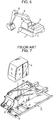
- the background art of the present invention is described by an example of an excavator shown in FIGS. 6 through 8 .
- the excavator shown in FIGS. 6 through 8 is provided with a crawler-type lower propelling body 1, and an upper slewing body 2 loaded on the lower propelling body 1 to be sleweable about an axis vertical to the ground.
- the upper slewing body 2 includes: an upper frame 3; a cab 4 serving as an operation room in which an operator is allowed to enter and disposed on a left portion or a right portion (generally, on the left portion) of the upper frame 3; a working attachment 6 having a boom 5 and the like and disposed on a lateral side (generally on a right side) of the cab 4 to be raised and lowered; and a counterweight 7 provided at a rear end of the upper frame 3.
- a front left portion of the upper frame 3 constitutes a cab attachment portion 8 as shown in FIGS. 7 and 8 .
- the cab 4 is loaded on the cab attachment portion 8 via a plurality of cab mounts 9.
- the cab mounts 9 are disposed at four corners on a bottom portion of the cab 4, in other words, disposed respectively at both ends in a lateral direction (left and right directions) of the construction machine on each of a front portion and a rear portion of the bottom portion in a longitudinal direction (front and rear directions) of the construction machine.
- each of the cab mounts 9 is formed as an anti-vibration mount which has an elastic member (normally made of an anti-vibration rubber material) and elastically supports the cab 4 so as to allow the cab 4 to be vertically and horizontally displaced relatively to the upper frame 3 within a predetermined range by the elastic deformation of the elastic member, thus damping vibrations of the cab 4 during driving.
- an elastic member normally made of an anti-vibration rubber material
- each of the cab mounts 9 exerts a resistive force, against a load acting on the cab 4 in such a direction as to remove the cab 4 from the cab attachment portion 8 of the upper frame 3 when the machine rolls over, by an elastic expansion of the elastic member of the cab mount 9.
- Japanese Unexamined Patent Publication No. 2006-348509 discloses a machine which includes, in addition to conventional cab mounts to be disposed at four corners on a bottom portion of a cab, other damping mechanisms to be disposed at respective positions away inwardly of the cab from the rear-side right and left pair of cab mounts. These other damping mechanisms are additionally provided to enhance supportability of a rear portion of the cab, in view of a point that the front portion of the cab is provided with relatively a few reinforcing members which are light, in order to secure a front view, while the front portion of the cab is provided with relatively many reinforcing members which are heavy.
- the excavator shown in FIGS. 6 through 8 has a drawback of requiring upsizing each of the cab mounts 9 to prevent the cab 4 from disengaging from the cab attachment portion 8 when the machine rolls over.
- the excavator rolls over on the side of the cab 4 that is, on such one side of the right and left sides that the cab 4 is placed down (generally toward the left side)
- the vertical plate 3a is a plate member standing upright on the upper frame 3 for supporting the boom 5) as a support.
- a tensile load initially acts on the left-side cab mounts 9, 9 located on the laterally outer-side of the cab, and, only after the fracture of the left-side cab mounts 9, 9, the right-side cab mounts 9, 9 can receive the load.
- high support strength especially for the left portion of the cab 4.
- Japanese Unexamined Patent Publication No. 2006-348509 discloses an excavator additionally provided with other damping mechanisms at a rear portion of a cab; however, even in this type of excavator, the cab is hard to efficiently prevent from its removal. Since the disclosed additional damping mechanisms are provided at respective positions largely away from the rear-side left and right pair of cab mounts toward a laterally middle position to enhance weight supportability of the cab for the great weight of the rear portion of the cab, an outermost cab mount of the cab mounts is broken first, when the excavator rolls over, and only thereafter, the additionally provided damping mechanism disposed at the inner side of the broken cab mount receives the load.
- the cab mounts and the additionally provided damping mechanisms successively and individually receive the load, which hinders enhancing the strength for preventing the cab from removal, regardless of the addition of the damping mechanisms.
- this technology is only capable of extending a time until the removal of the cab, not providing a fundamental solution.
- An object of the invention is to provide a construction machine including an upper frame and a cab, which can be effectively prevented from a removal from the upper frame, without upsized cab mounts.
- a construction machine to be provided by the invention includes a lower propelling body, and an upper slewing body loaded on the lower propelling body to be slewable about an axis vertical to the ground.
- the upper slewing body includes an upper frame, a cab provided on a right portion or a left portion of the upper frame and adapted to allow an operator to enter therein, and a plurality of cab mounts interposed between the cab and the upper frame.
- the cab mounts are disposed at respective lateral ends on front and rear portions of the cab respectively and configured to exert a resistive force against a load acting on the cab in such a direction as to remove the cab from the upper frame when the construction machine rolls over.
- the cab mounts include, on at least one of the front portion and the rear portion of the cab, a first outer-side cab mount and a second outer-side cab mount which are disposed at an outer side of the lateral ends of the cab.
- the first and second outer-side cab mounts are juxtaposed with a small enough distance to cause the first and second outer-side cab mounts to receive the load concurrently when the construction machine rolls over toward a side of the cab.
- the expression "the first and second outer-side cab mounts concurrently receive the load” includes not only a case where the load starts acting on the first and second outer-side cab mounts simultaneously, but also a case where the load starts acting on one of the first and second outer-side cab mounts and, before the one outer-side cab mount is ruptured, in other words, before the support of the cab by the one outer-side cab mount substantially disappears, the load is acted on the other of the first and second outer-side cab mounts.
- the first through third embodiments are examples, in which an excavator substantially the same as the excavator shown in FIG. 6 is applied to the invention.
- the excavators of the first through third embodiments are substantially the same as the excavator shown in FIG. 6 except for a point that each of the excavators of the first through third embodiments is provided with an upper frame 11, a cab 12 and a plurality of cab mounts 14, 15, 16, 17A and 17B, in place of the upper frame 3, the cab 4 and the cab mounts 9 shown in FIGS. 6 through 8 .
- a front left portion of the upper frame 11 constitutes a cab attachment portion 13, and the cab 12 is loaded on the cab attachment portion 13 via the cab mounts 14-16, 17A and 17B.
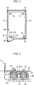
- the first embodiment is described referring to FIGS. 1 through 3 .
- the first embodiment includes the following arrangement: the cab mounts 14, 15 and 16 are disposed at a front-side left position, a front-side right position and a rear-side right position, that is, a laterally inner side of the cab, of the cab attachment portion 13, respectively; the cab mounts 17A and 17B corresponding to a first outer-side cab mount and a second outer-side cab mount of the invention respectively are juxtaposed laterally and possibly closely to each other, at a rear-side left position, i.e., at a laterally outer side of the cab.
- the cab mounts 17A and 17B will be called as a “first rear-side outer-side cab mount 17A” and a “second rear-side outer-side cab mount 17B", respectively.
- All the cab mounts 14 through 16, 17A and 17B which are the same products, in other words, have the same shape (a shape having a tubular outer surface), size, structure as each other, are attached to a bottom plate 18 disposed on an inner side of a left-side panel 21 of the cab 12 as shown in FIG. 3 , by bolts 19, and disposed on a bottom plate 20 of the upper frame 11.
- the cab 12 has a cab frame, which has a front left pillar 22, a front right pillar 23, a left middle pillar 24, a left rear pillar 25 and a right rear pillar 26, as shown in FIG. 2 .
- a rear portion of the cab 12 is constituted of a large number of reinforcing members to have high strength and high rigidity as compared with a front portion of the cab 12.
- the first rear-side outer-side cab mount 17A and the second rear-side outer-side cab mount 17B are disposed near the base of the left rear pillar 25 having a highest strength and rigidity among the pillars 22 through 26.
- Each of the cab mounts 14 through 16, 17A and 17B has an elastic member 27.
- the elastic member 27 is made of e.g. an anti-vibration rubber material.
- the cab mounts 14 through 16, 17A and 17B elastically support the cab 12 so as to allow the cab 12 to be vertically and horizontally displaced within a predetermined range by elastic deformation of the elastic members 27.
- each of the cab mounts is constructed so as to exert a resistive force, by elastic expansion of the elastic member 27, against a load acting on the cab 12 in such a direction as to remove the cab 12 from the upper frame 11. The specific reason is as follows. In the case where the excavator rolls over, especially on the side of the cab 4 shown in FIG.
- each of the cab mount should be designed to provide a resistance against the load due to the above moment.
- the interval C between the first cab mount 17A and the second cab mount 17B is set to a small enough value to cause the left-side or the outer-side first cab mount 17A and the right-side or the inner-side second cab mount 17B to start exerting a resistive force in this order against a rollover load W, which means a load acting when the machine rolls over, in other words, a small enough value to cause the right-side or second rear-side outer-side cab mount 17B to start expanding during the inward and upward elastic-expansion of the elastic member 27 of the left-side first cab mount 17A due to the rollover load W initially acting on the left-side first cab mount 17A, i.e., before the rupture of the elastic member 27 of the first cab mount 17A.
- first and second outer-side cab mounts 17A and 17B are juxtaposed with a small enough distance to allow cab mounts 17A and 17B to receive the rollover load W concurrently.
- This arrangement enables the first and second outer-side cab mounts 17A and 17B to share the rollover load W between them, thereby inhibiting fracture of the first and second outer-side cab mounts 17A and 17B themselves to thus enhance the cab-removal-prevention effect, as compared with the conventional arts.
- the first and second cab mounts 17A and 17B start to exert a resistive force against the rollover load W in this order with a slightly small time lag; this permits, for example, a machine having a cab 12 designed to allow a slight deformation of the cab 12 due to an initial load when the machine rolls over to thereby obtain a shock-absorption effect, in other words, a machine to which the rollover load W is transmitted from the outer side to the inner side while being reduced, to exhibit an enhanced cab-removal-prevention effect.
- the enhancement of the cab-removal-prevention effect eliminates the need for providing an additional grapple for cab removal prevention, other than the cab mounts 14 through 16, 17A and 17B, or allows the grapple to be miniaturized or simplified. This makes it possible to prevent the cab 12 from removal while not involving a disadvantage such as an increase in the number of assembling steps, cost, or installation space.
- the structure shown in FIG. 3 is further provided with a reinforcing member 28 which is disposed across the elastic members 27 of the first and second outer-side cab mounts 17A and 17B.
- the reinforcing member 28, which is fixed to the lower surface of the bottom plate 18 of the cab 12 to reinforce the bottom plate 18, is interposed between the respective elastic members 27 of the first and second outer-side cab mounts 17A, 17B, and the bottom plate 18 of the cab 12, and is fixed to the elastic members 27 by the bolts 19 for the above-mentioned fixture of the first and second outer-side cab mounts 17A and 17B to the bottom plate 18, respectively.
- the reinforcing member 28 enhances the integrity of the first and second outer-side cab mounts 17A and 17B to promote the load acting on the first outer-side cab mount 17A to also act on the second outer-side cab mount 17B.
- the shape of the reinforcing member 28 may be a flat plate shape as shown in FIG. 3 , or may be a corrugated shape or a block-like shape.
- FIG. 4 is a plan view of a cab 12 according to a second embodiment of the invention.
- first and second cab mounts 17A and 17B are juxtaposed longitudinally with a small enough distance to cause the first and second cab mounts 17A and 17B to start exerting a resistive force concurrently against the rollover load W.
- This positional arrangement enables the first and second cab mounts 17A and 17B to receive the rollover load W from an initial stage when the machine rolls over.
- the second embodiment is particularly advantageous in cab removal prevention, for example, in a machine having a cab designed to prevent deformation of the cab at an initial load, in other words, in a machine which provides no expectation of shock absorption effect against an initial load.
- FIG. 5 is a plan view of a cab 12 according to a third embodiment of the invention.
- the third embodiment includes a first front-side outer-side cab mount 14A and a second front-side outer-side cab mount 14B, which are juxtaposed closely to each other, in place of the single cab mount 14 disposed at the front-side outer-side (left-side) of the cab 12 as in the first embodiment.
- the first and second front-side outer-side cab mounts 14A and 14B juxtaposed laterally and closely and the first and second rear-side outer-side cab mounts 17A and 17B are arranged at the outer side (left side) on a front portion and a rear portion of the cab 12, respectively.
- This arrangement allows the left and right cab mounts 14A and 14B, and the left and right cab mounts 17A and 17B to share a rollover load W at front and rear ends of the cab 12 respectively, thereby enhancing the cab-removal-prevention effect.
- the invention is not limited to the first through third embodiments but may include various modifications obvious to persons skilled in the art having common knowledge and skills in the art.
- the invention may include an embodiment in which first and second outer-side cab mounts are juxtaposed laterally or longitudinally only at a front-side outer side of a cab, and an embodiment in which first and second outer-side cab mounts are juxtaposed longitudinally at an outer side on respective front and rear ends of a cab.
- the invention does not preclude juxtaposing, in addition to first and second outer-side cab mounts, one or more cab mounts for a large-sized cab or a large-sized and heavy-weighted excavator.
- the invention does not preclude disposing, in addition to cab mounts at lateral ends on longitudinal ends of a cab, another cab mount at a position other than the above position, e.g. at a laterally middle position, of the cab.
- the invention may be applied to an excavator having a cab disposed on a right portion of an upper frame, or to a construction machine other than an excavator, which machine has an upper frame and a cab disposed on a left portion or a right portion of the upper frame via a cab mount, similarly to the excavator.
- the invention provides a construction machine including an upper frame and a cab, which can be effectively prevented from a removal from the upper frame, without upsized cab mounts.
- This construction machine includes a lower propelling body, and an upper slewing body loaded on the lower propelling body to be slewable about an axis vertical to the ground.
- the upper slewing body includes an upper frame, a cab provided on a right portion or a left portion of the upper frame and adapted to allow an operator to enter therein, and a plurality of cab mounts interposed between the cab and the upper frame.
- the cab mounts are disposed at respective lateral ends on front and rear portions of the cab respectively and configured to exert a resistive force against a load acting on the cab in such a direction as to remove the cab from the upper frame when the construction machine rolls over.
- the cab mounts include, on at least one of the front portion and the rear portion of the cab, a first outer-side cab mount and a second outer-side cab mount which are disposed at an outer side of the lateral ends of the cab.
- the first and second outer-side cab mounts are juxtaposed with a small enough distance to cause the first and second outer-side cab mounts to receive the load concurrently when the construction machine rolls over toward a side of the cab.
- the first and second outer-side cab mounts juxtaposed closely to each other are able to concurrently receive a load acting on the cab in such a direction as to remove the cab from the upper frame and concurrently exert resistive forces respectively when the construction machine rolls over toward the side of the cab, thereby sharing the load.
- a load acting on the cab in such a direction as to remove the cab from the upper frame and concurrently exert resistive forces respectively when the construction machine rolls over toward the side of the cab, thereby sharing the load.
- the arrangement of the first and second outer-side cab mounts eliminates the need for providing, in addition to the cab mounts, a grapple for preventing cab removal or enables the grapple to be miniaturized or simplified, thereby enhancing the cab detachment preventive effect without an intolerable increase in the number of assembling steps, the cost and the installation space.
- each of the first and second outer-side cab mounts may include an elastic member adapted to elastically support the cab and expand due to a load acting when the construction machine rolls over toward the side of the cab to thereby exert a resistive force against the load.
- the construction machine further includes a reinforcing member disposed across the respective elastic members of the first and second outer-side cab mounts and fixed to the elastic members.
- the reinforcing member enhances the integrity of the first and second outer-side cab mounts, and promotes the load acting on the first outer-side cab mount to also act on the second outer-side cab mount.
- the first and second outer-side cab mounts are juxtaposed as respective rear-side outer-side cab mounts of the cab. This juxtaposition enhances the effect of preventing removal of the rear portion of the cab to effectively reduce deformation of the cab, thereby enabling a structure suitable for the ROPS (rollover protective structure) standards for preventing deformation of a cab to be realized.
- ROPS rollover protective structure
- the first and second outer-side cab mounts can be juxtaposed, for example, in a lateral direction of the cab. This lateral juxtaposition enables the laterally outer-side cab mount of the first and second outer-side cab mounts to receive the load for the first time when the construction machine rolls over toward the side of the cab, and enables the other of the first and second outer-side cab mounts to start receiving the load so as to share the load with the laterally outer-side cab mount while the laterally outer-side cab mount receives the load, in other words, before the fracture of the laterally outer-side cab mount.
- the arrangement allows, for example, a machine having a cab designed to allow the cab to be slightly deformed due to an initial load when the machine rolls over to thus exhibit shock-absorption effect, in other words, a machine in which the load is transferred the load from the outer side toward the inner side of the machine while being reduced, to exhibit the enhanced cab-removal-prevention effect.
- the first and second outer-side cab mounts may be juxtaposed longitudinally of the cab. This longitudinal juxtaposition enables the first and second outer-side cab mounts to share the load from an initial stage at the same timing when the construction machine rolls over toward the side of the cab substantially. Therefore, this juxtaposition enables, for example, a machine having a cab designed to prevent deformation of a cab due to an initial load, in other words, a machine providing no expectation of shock-absorption effect against an initial load, to exhibit the enhanced cab-removal-prevention effect.
- the construction machine is provided with a lower propelling body and an upper slewing body.
- the upper slewing body has an upper frame, a cab disposed on a left portion or a right portion of the upper frame, and cab mounts.
- the cab mounts are disposed at lateral ends on each of front and rear portions of the cab respectively, including, on at least one of the front and rear portions, first and second outer-side cab mounts disposed at the outer side of lateral ends of the cab.
- the first and second outer-side cab mounts are juxtaposed with a small enough distance to receive a rollover load concurrently when the construction machine rolls over toward a side of the cab.
Landscapes
- Engineering & Computer Science (AREA)
- Chemical & Material Sciences (AREA)
- Combustion & Propulsion (AREA)
- Transportation (AREA)
- Mechanical Engineering (AREA)
- Mining & Mineral Resources (AREA)
- Civil Engineering (AREA)
- General Engineering & Computer Science (AREA)
- Structural Engineering (AREA)
- Body Structure For Vehicles (AREA)
- Component Parts Of Construction Machinery (AREA)
Claims (6)
- Baumaschine mit:einem unteren Antriebskörper (1); undeinem oberen Schwenkkörper (2), der auf dem unteren Antriebskörper (1) schwenkbar um eine zum Boden vertikale Achse geladen ist, wobei:der obere Schwenkkörper (2) einen oberen Rahmen (11), eine Kabine (12), die an einem linken Abschnitt oder einem rechten Abschnitt des oberen Rahmens (11) vorgesehen ist und gestaltet ist, um einem Bediener zu ermöglichen, in diese zu kommen, und eine Vielzahl von Kabinenlagerungen (14, 15, 16, 17A, 17B) enthält, die zwischen der Kabine (12) und dem oberen Rahmen (11) angeordnet sind;die Kabinenlagerungen (14, 15, 16, 17A, 17B) jeweils an seitlichen Enden an jeweils einem Vorderabschnitt und einem hinteren Abschnitt der Kabine (12) angeordnet sind und gestaltet sind, um eine Widerstandskraft gegen eine Last auszuüben, die auf die Kabine (12) in solch eine Richtung wirkt, um die Kabine (12) von dem oberen Rahmen (11) zu entfernen, wenn die Baumaschine umkippt;dadurch gekennzeichnet, dassdie Kabinenlagerungen (14, 15, 16, 17A, 17B) an dem Vorderabschnitt und/oder dem hinteren Abschnitt der Kabine (12) eine erste Außenseitenkabinenlagerung (17A) und eine zweite Außenseitenkabinenlagerung (17B) enthalten, die an einer Außenseite der seitlichen Enden der Kabine (12) angeordnet sind, wobei die erste und zweite Außenseitenkabinenlagerung (17A, 17B) mit einem Abstand nebeneinander angeordnet sind, der klein genug ist, um der ersten und zweiten Außenseitenkabinenlagerung (17A, 17B) zu ermöglichen, eine Last gleichzeitig aufzunehmen, wenn die Baumaschine in Richtung einer Seite der Kabine (12) umkippt.
- Baumaschine gemäß Anspruch 1, wobei jede der ersten und zweiten Außenseitenkabinenlagerungen (17A, 17B) ein elastisches Bauteil (27) zum elastischen Stützen der Kabine (12) enthält, wobei das elastische Bauteil (27) gestaltet ist, um sich aufgrund einer Last elastisch auszudehnen, wenn die Baumaschine in Richtung der Seite der Kabine (12) umkippt, um dadurch eine Widerstandskraft gegen die Last auszuüben.
- Baumaschine gemäß Anspruch 2, des Weiteren mit einem Verstärkungsbauteil (28), das quer über die jeweiligen elastischen Bauteile (27) der ersten und zweiten Außenseitenkabinenlagerung (17A, 17B) angeordnet ist und an die elastischen Bauteile (27) fixiert ist.
- Baumaschine gemäß Anspruch 1, wobei die erste und zweite Außenseitenkabinenlagerung (17A, 17B) als jeweilige Rückseitenaußenseitenkabinenlagerungen (17A, 17B) der Kabinenlagerungen (14, 15, 16, 17A, 17B) nebeneinander angeordnet sind.
- Baumaschine gemäß Anspruch 1, wobei die erste und zweite Außenseitenkabinenlagerung (17A, 17B) seitlich der Kabine (12) nebeneinander angeordnet sind.
- Baumaschine gemäß Anspruch 1, wobei die erste und zweite Außenseitenkabinenlagerung (17A, 17B) längs der Kabine (12) nebeneinander angeordnet sind.
Applications Claiming Priority (1)
| Application Number | Priority Date | Filing Date | Title |
|---|---|---|---|
| JP2011147915A JP5810683B2 (ja) | 2011-07-04 | 2011-07-04 | 建設機械のキャブ支持構造 |
Publications (3)
| Publication Number | Publication Date |
|---|---|
| EP2543576A2 EP2543576A2 (de) | 2013-01-09 |
| EP2543576A3 EP2543576A3 (de) | 2016-12-28 |
| EP2543576B1 true EP2543576B1 (de) | 2018-12-05 |
Family
ID=46466198
Family Applications (1)
| Application Number | Title | Priority Date | Filing Date |
|---|---|---|---|
| EP12174709.1A Not-in-force EP2543576B1 (de) | 2011-07-04 | 2012-07-03 | Konstruktionsmaschine mit Kabine |
Country Status (4)
| Country | Link |
|---|---|
| US (1) | US8517457B2 (de) |
| EP (1) | EP2543576B1 (de) |
| JP (1) | JP5810683B2 (de) |
| CN (1) | CN102864797B (de) |
Families Citing this family (27)
| Publication number | Priority date | Publication date | Assignee | Title |
|---|---|---|---|---|
| DE102010015163A1 (de) * | 2010-04-16 | 2011-10-20 | Liebherr-Hydraulikbagger Gmbh | Baumaschine oder Umschlaggerät |
| JP5706110B2 (ja) * | 2010-07-29 | 2015-04-22 | プレス工業株式会社 | 建設機械のキャブフレーム構造 |
| EP2522879A3 (de) * | 2011-05-12 | 2017-09-20 | Carl Freudenberg KG | Anordnung bestehend aus einem Lager und einem Zuganker |
| JP5278509B2 (ja) * | 2011-07-27 | 2013-09-04 | コベルコ建機株式会社 | 建設機械の機器取付方法及び同装置 |
| DE102011109080A1 (de) * | 2011-07-27 | 2013-01-31 | Liebherr-Hydraulikbagger Gmbh | Drehbühnenelement für eine Baumaschine |
| USD966958S1 (en) | 2011-09-27 | 2022-10-18 | Oshkosh Corporation | Grille element |
| US9045014B1 (en) | 2012-03-26 | 2015-06-02 | Oshkosh Defense, Llc | Military vehicle |
| US8955859B1 (en) * | 2011-09-27 | 2015-02-17 | Oshkosh Corporation | Isolated cab mounting system for an armored vehicle |
| US9068620B2 (en) * | 2013-02-27 | 2015-06-30 | The Pullman Company | Body mount having suspended ring member |
| JP6174969B2 (ja) * | 2013-10-29 | 2017-08-02 | キャタピラー エス エー アール エル | 建設機械のキャブ支持構造 |
| JP5979187B2 (ja) * | 2014-08-01 | 2016-08-24 | コベルコ建機株式会社 | 建設機械のキャブ支持構造 |
| JP6557019B2 (ja) * | 2015-02-16 | 2019-08-07 | キャタピラー エス エー アール エル | 建設機械 |
| CN104787592A (zh) * | 2015-04-15 | 2015-07-22 | 苏州市力神起重运输机械制造有限公司 | 一种斗轮机驾驶室用缓冲托架 |
| US10494038B2 (en) * | 2015-05-13 | 2019-12-03 | Kobe Steel, Ltd. | Upper slewing body |
| JP6617020B2 (ja) * | 2015-12-22 | 2019-12-04 | 株式会社加藤製作所 | 建設機械のキャブ |
| AU2017248349B2 (en) | 2016-04-08 | 2021-11-11 | Oshkosh Corporation | Leveling system for lift device |
| JP2018025047A (ja) * | 2016-08-10 | 2018-02-15 | 株式会社小松製作所 | 作業車両 |
| JP6914640B2 (ja) * | 2016-11-18 | 2021-08-04 | 住友建機株式会社 | ショベル |
| US10093264B2 (en) | 2016-12-27 | 2018-10-09 | Cnh Industrial America Llc | Cab mount for a work vehicle |
| KR102644709B1 (ko) * | 2017-02-28 | 2024-03-06 | 에이치디현대인프라코어 주식회사 | 건설기계의 캐빈 조립체 |
| US10745065B2 (en) * | 2018-04-16 | 2020-08-18 | Howe & Howe Inc. | Vehicle with pneumatically suspended operator compartment |
| CN113184065A (zh) * | 2021-05-08 | 2021-07-30 | 徐工集团工程机械股份有限公司 | 工程车辆的驾驶室及工程车辆 |
| US11840284B2 (en) | 2021-11-03 | 2023-12-12 | Zoomlion Heavy Industry Na, Inc. | Modular saddle mount with isolator retained in a frame for reducing vibration in heavy equipment cabs |
| US11718355B2 (en) | 2021-11-03 | 2023-08-08 | Zoomlion Heavy Industry N.A., Inc. | Modular saddle mount and modified frame cross member for reducing vibration in heavy equipment cabs |
| US11904953B2 (en) | 2021-11-03 | 2024-02-20 | Zoomlion Heavy Industry Na, Inc. | Modular saddle mount retained in a frame cross member for reducing vibration in heavy equipment cabs |
| CN114454968B (zh) * | 2022-02-23 | 2023-08-01 | 扬州丰源车身制造有限公司 | 一种具有抗压结构的驾驶室总成及其加工方法 |
| FI20245437A1 (fi) * | 2024-04-08 | 2025-10-09 | Ponsse Oyj | Työkoneen ohjaamo, työkone ja menetelmä työkoneen ohjaamon mitoittamiseksi |
Family Cites Families (18)
| Publication number | Priority date | Publication date | Assignee | Title |
|---|---|---|---|---|
| US5551826A (en) * | 1995-04-10 | 1996-09-03 | New Holland North America, Inc. | Skid steer loader cab mounting apparatus |
| MXPA01010333A (es) * | 1999-05-26 | 2003-07-21 | Int Truck Intellectual Prop Co | Refuerzo simetrico de tablero de instrumentos. |
| US6427795B1 (en) * | 1999-10-29 | 2002-08-06 | Caterpillar Elphinstone Pty. Ltd. | Underground roll over protection structure |
| JP3671790B2 (ja) | 2000-01-13 | 2005-07-13 | 日立建機株式会社 | 建設機械の運転室支持装置 |
| JP3636966B2 (ja) * | 2000-05-16 | 2005-04-06 | 日立建機株式会社 | 建設機械のキャビン取付構造および防振支持機構の交換方法 |
| US6374935B1 (en) * | 2000-06-07 | 2002-04-23 | Caterpillar S.A.R.L. | Vibration-isolation cab mounting apparatus |
| JP4429595B2 (ja) | 2002-12-11 | 2010-03-10 | 株式会社小松製作所 | キャブ支持構造 |
| KR100678649B1 (ko) * | 2004-10-06 | 2007-02-06 | 볼보 컨스트럭션 이키프먼트 홀딩 스웨덴 에이비 | 중장비 운전실의 하중지지장치 및 그 제작방법 |
| JP2006348509A (ja) * | 2005-06-14 | 2006-12-28 | Sumitomo (Shi) Construction Machinery Manufacturing Co Ltd | 建設機械のキャブ支持構造 |
| US7347488B2 (en) * | 2005-08-31 | 2008-03-25 | Caterpillar Inc. | Vehicle cab including centrally-located “A post” |
| US7237830B1 (en) * | 2006-03-17 | 2007-07-03 | International Truck Intellectual Property Company, Llc | Leaf spring truck cab suspension |
| US8182024B2 (en) * | 2006-05-31 | 2012-05-22 | Caterpillar Inc. | Structure and a system for connecting a machine cab to a supporting frame |
| JP4143980B2 (ja) * | 2006-10-20 | 2008-09-03 | いすゞ自動車株式会社 | キャブのフロア構造 |
| US7607721B2 (en) * | 2006-11-08 | 2009-10-27 | Caterpillar Inc. | Operator cab tilting apparatus |
| CN101553629B (zh) * | 2006-11-30 | 2012-08-15 | 株式会社小松制作所 | 工作机械的驾驶员驾驶室支承装置 |
| US8657251B2 (en) * | 2006-11-30 | 2014-02-25 | Komatsu Ltd. | Cab supporting apparatus of work machine |
| KR20110062290A (ko) * | 2009-12-03 | 2011-06-10 | 볼보 컨스트럭션 이큅먼트 에이비 | 진동 흡수장치와 운전자 보호구조물 하중 지지장치가 일원화된 건설장비 |
| JP2011147915A (ja) | 2010-01-25 | 2011-08-04 | Panasonic Corp | インクジェットヘッドおよびインクジェット装置 |
-
2011
- 2011-07-04 JP JP2011147915A patent/JP5810683B2/ja not_active Expired - Fee Related
-
2012
- 2012-07-02 US US13/540,214 patent/US8517457B2/en not_active Expired - Fee Related
- 2012-07-03 EP EP12174709.1A patent/EP2543576B1/de not_active Not-in-force
- 2012-07-04 CN CN201210237969.1A patent/CN102864797B/zh not_active Expired - Fee Related
Non-Patent Citations (1)
| Title |
|---|
| None * |
Also Published As
| Publication number | Publication date |
|---|---|
| US8517457B2 (en) | 2013-08-27 |
| CN102864797B (zh) | 2016-04-13 |
| JP2013014927A (ja) | 2013-01-24 |
| EP2543576A3 (de) | 2016-12-28 |
| EP2543576A2 (de) | 2013-01-09 |
| JP5810683B2 (ja) | 2015-11-11 |
| CN102864797A (zh) | 2013-01-09 |
| US20130009423A1 (en) | 2013-01-10 |
Similar Documents
| Publication | Publication Date | Title |
|---|---|---|
| EP2543576B1 (de) | Konstruktionsmaschine mit Kabine | |
| JP5076845B2 (ja) | ベースフレームとキャブとの取付構造及びこれを備えた建設機械 | |
| CN110239624A (zh) | 车辆下部构造 | |
| EP2599693A1 (de) | Struktur für den unteren teil einer fahrzeugkarosserie | |
| US8020925B2 (en) | Front structure of cab-over type vehicle | |
| EP3050782B1 (de) | Struktur für den hinteren teil einer fahrzeugkarosserie | |
| EP2551411B1 (de) | Verfahren und Vorrichtung zur Montage einer Vorrichtung in einer Baumaschine | |
| JP5582167B2 (ja) | 建設機械 | |
| JP4655815B2 (ja) | 建設機械のキャビン | |
| JP2006312441A (ja) | 建設機械の運転室保護構造 | |
| JP2010042761A (ja) | キャブ支持構造 | |
| EP2960380A1 (de) | Baumaschine | |
| EP2907928A1 (de) | Bodenelement und Arbeitsmaschine | |
| EP2915725B1 (de) | Kabinenverstärkungsstruktur | |
| JP2008105669A (ja) | 上部体及びこれを備えた建設機械 | |
| JP5991019B2 (ja) | 建設機械 | |
| JP2008291541A (ja) | 建設機械 | |
| JP2013241817A (ja) | 建設機械 | |
| JPWO2020170578A1 (ja) | 車載部品支持構造 | |
| JP2025070305A (ja) | 車体前部構造 | |
| JP2024179902A (ja) | 車両用バッテリの支持構造 | |
| JP2015086543A (ja) | 建設機械のキャブ支持構造 | |
| KR20240093094A (ko) | 차량의 샤시프레임 | |
| WO2020059669A1 (ja) | サスペンションサブフレーム構造 | |
| JP6893385B2 (ja) | 車両前部構造 |
Legal Events
| Date | Code | Title | Description |
|---|---|---|---|
| PUAI | Public reference made under article 153(3) epc to a published international application that has entered the european phase |
Free format text: ORIGINAL CODE: 0009012 |
|
| AK | Designated contracting states |
Kind code of ref document: A2 Designated state(s): AL AT BE BG CH CY CZ DE DK EE ES FI FR GB GR HR HU IE IS IT LI LT LU LV MC MK MT NL NO PL PT RO RS SE SI SK SM TR |
|
| AX | Request for extension of the european patent |
Extension state: BA ME |
|
| REG | Reference to a national code |
Ref country code: DE Ref legal event code: R079 Ref document number: 602012054255 Country of ref document: DE Free format text: PREVIOUS MAIN CLASS: B62D0027040000 Ipc: E02F0009160000 |
|
| PUAL | Search report despatched |
Free format text: ORIGINAL CODE: 0009013 |
|
| AK | Designated contracting states |
Kind code of ref document: A3 Designated state(s): AL AT BE BG CH CY CZ DE DK EE ES FI FR GB GR HR HU IE IS IT LI LT LU LV MC MK MT NL NO PL PT RO RS SE SI SK SM TR |
|
| AX | Request for extension of the european patent |
Extension state: BA ME |
|
| RIC1 | Information provided on ipc code assigned before grant |
Ipc: E02F 9/16 20060101AFI20161124BHEP Ipc: B62D 27/04 20060101ALI20161124BHEP Ipc: B62D 33/06 20060101ALI20161124BHEP |
|
| STAA | Information on the status of an ep patent application or granted ep patent |
Free format text: STATUS: REQUEST FOR EXAMINATION WAS MADE |
|
| 17P | Request for examination filed |
Effective date: 20170619 |
|
| RBV | Designated contracting states (corrected) |
Designated state(s): AL AT BE BG CH CY CZ DE DK EE ES FI FR GB GR HR HU IE IS IT LI LT LU LV MC MK MT NL NO PL PT RO RS SE SI SK SM TR |
|
| GRAP | Despatch of communication of intention to grant a patent |
Free format text: ORIGINAL CODE: EPIDOSNIGR1 |
|
| STAA | Information on the status of an ep patent application or granted ep patent |
Free format text: STATUS: GRANT OF PATENT IS INTENDED |
|
| INTG | Intention to grant announced |
Effective date: 20180622 |
|
| GRAS | Grant fee paid |
Free format text: ORIGINAL CODE: EPIDOSNIGR3 |
|
| GRAA | (expected) grant |
Free format text: ORIGINAL CODE: 0009210 |
|
| GRAA | (expected) grant |
Free format text: ORIGINAL CODE: 0009210 |
|
| STAA | Information on the status of an ep patent application or granted ep patent |
Free format text: STATUS: THE PATENT HAS BEEN GRANTED |
|
| AK | Designated contracting states |
Kind code of ref document: B1 Designated state(s): AL AT BE BG CH CY CZ DE DK EE ES FI FR GB GR HR HU IE IS IT LI LT LU LV MC MK MT NL NO PL PT RO RS SE SI SK SM TR |
|
| REG | Reference to a national code |
Ref country code: GB Ref legal event code: FG4D |
|
| RIN1 | Information on inventor provided before grant (corrected) |
Inventor name: YAMAMOTO, KEIJI |
|
| REG | Reference to a national code |
Ref country code: CH Ref legal event code: EP |
|
| REG | Reference to a national code |
Ref country code: AT Ref legal event code: REF Ref document number: 1073243 Country of ref document: AT Kind code of ref document: T Effective date: 20181215 |
|
| REG | Reference to a national code |
Ref country code: IE Ref legal event code: FG4D |
|
| REG | Reference to a national code |
Ref country code: DE Ref legal event code: R096 Ref document number: 602012054255 Country of ref document: DE |
|
| REG | Reference to a national code |
Ref country code: NL Ref legal event code: MP Effective date: 20181205 |
|
| REG | Reference to a national code |
Ref country code: AT Ref legal event code: MK05 Ref document number: 1073243 Country of ref document: AT Kind code of ref document: T Effective date: 20181205 |
|
| REG | Reference to a national code |
Ref country code: LT Ref legal event code: MG4D |
|
| PG25 | Lapsed in a contracting state [announced via postgrant information from national office to epo] |
Ref country code: FI Free format text: LAPSE BECAUSE OF FAILURE TO SUBMIT A TRANSLATION OF THE DESCRIPTION OR TO PAY THE FEE WITHIN THE PRESCRIBED TIME-LIMIT Effective date: 20181205 Ref country code: NO Free format text: LAPSE BECAUSE OF FAILURE TO SUBMIT A TRANSLATION OF THE DESCRIPTION OR TO PAY THE FEE WITHIN THE PRESCRIBED TIME-LIMIT Effective date: 20190305 Ref country code: LV Free format text: LAPSE BECAUSE OF FAILURE TO SUBMIT A TRANSLATION OF THE DESCRIPTION OR TO PAY THE FEE WITHIN THE PRESCRIBED TIME-LIMIT Effective date: 20181205 Ref country code: AT Free format text: LAPSE BECAUSE OF FAILURE TO SUBMIT A TRANSLATION OF THE DESCRIPTION OR TO PAY THE FEE WITHIN THE PRESCRIBED TIME-LIMIT Effective date: 20181205 Ref country code: ES Free format text: LAPSE BECAUSE OF FAILURE TO SUBMIT A TRANSLATION OF THE DESCRIPTION OR TO PAY THE FEE WITHIN THE PRESCRIBED TIME-LIMIT Effective date: 20181205 Ref country code: LT Free format text: LAPSE BECAUSE OF FAILURE TO SUBMIT A TRANSLATION OF THE DESCRIPTION OR TO PAY THE FEE WITHIN THE PRESCRIBED TIME-LIMIT Effective date: 20181205 Ref country code: HR Free format text: LAPSE BECAUSE OF FAILURE TO SUBMIT A TRANSLATION OF THE DESCRIPTION OR TO PAY THE FEE WITHIN THE PRESCRIBED TIME-LIMIT Effective date: 20181205 Ref country code: BG Free format text: LAPSE BECAUSE OF FAILURE TO SUBMIT A TRANSLATION OF THE DESCRIPTION OR TO PAY THE FEE WITHIN THE PRESCRIBED TIME-LIMIT Effective date: 20190305 |
|
| PG25 | Lapsed in a contracting state [announced via postgrant information from national office to epo] |
Ref country code: AL Free format text: LAPSE BECAUSE OF FAILURE TO SUBMIT A TRANSLATION OF THE DESCRIPTION OR TO PAY THE FEE WITHIN THE PRESCRIBED TIME-LIMIT Effective date: 20181205 Ref country code: GR Free format text: LAPSE BECAUSE OF FAILURE TO SUBMIT A TRANSLATION OF THE DESCRIPTION OR TO PAY THE FEE WITHIN THE PRESCRIBED TIME-LIMIT Effective date: 20190306 Ref country code: SE Free format text: LAPSE BECAUSE OF FAILURE TO SUBMIT A TRANSLATION OF THE DESCRIPTION OR TO PAY THE FEE WITHIN THE PRESCRIBED TIME-LIMIT Effective date: 20181205 Ref country code: RS Free format text: LAPSE BECAUSE OF FAILURE TO SUBMIT A TRANSLATION OF THE DESCRIPTION OR TO PAY THE FEE WITHIN THE PRESCRIBED TIME-LIMIT Effective date: 20181205 |
|
| PG25 | Lapsed in a contracting state [announced via postgrant information from national office to epo] |
Ref country code: NL Free format text: LAPSE BECAUSE OF FAILURE TO SUBMIT A TRANSLATION OF THE DESCRIPTION OR TO PAY THE FEE WITHIN THE PRESCRIBED TIME-LIMIT Effective date: 20181205 |
|
| PG25 | Lapsed in a contracting state [announced via postgrant information from national office to epo] |
Ref country code: PT Free format text: LAPSE BECAUSE OF FAILURE TO SUBMIT A TRANSLATION OF THE DESCRIPTION OR TO PAY THE FEE WITHIN THE PRESCRIBED TIME-LIMIT Effective date: 20190405 Ref country code: CZ Free format text: LAPSE BECAUSE OF FAILURE TO SUBMIT A TRANSLATION OF THE DESCRIPTION OR TO PAY THE FEE WITHIN THE PRESCRIBED TIME-LIMIT Effective date: 20181205 Ref country code: PL Free format text: LAPSE BECAUSE OF FAILURE TO SUBMIT A TRANSLATION OF THE DESCRIPTION OR TO PAY THE FEE WITHIN THE PRESCRIBED TIME-LIMIT Effective date: 20181205 |
|
| PG25 | Lapsed in a contracting state [announced via postgrant information from national office to epo] |
Ref country code: EE Free format text: LAPSE BECAUSE OF FAILURE TO SUBMIT A TRANSLATION OF THE DESCRIPTION OR TO PAY THE FEE WITHIN THE PRESCRIBED TIME-LIMIT Effective date: 20181205 Ref country code: SM Free format text: LAPSE BECAUSE OF FAILURE TO SUBMIT A TRANSLATION OF THE DESCRIPTION OR TO PAY THE FEE WITHIN THE PRESCRIBED TIME-LIMIT Effective date: 20181205 Ref country code: SK Free format text: LAPSE BECAUSE OF FAILURE TO SUBMIT A TRANSLATION OF THE DESCRIPTION OR TO PAY THE FEE WITHIN THE PRESCRIBED TIME-LIMIT Effective date: 20181205 Ref country code: RO Free format text: LAPSE BECAUSE OF FAILURE TO SUBMIT A TRANSLATION OF THE DESCRIPTION OR TO PAY THE FEE WITHIN THE PRESCRIBED TIME-LIMIT Effective date: 20181205 Ref country code: IS Free format text: LAPSE BECAUSE OF FAILURE TO SUBMIT A TRANSLATION OF THE DESCRIPTION OR TO PAY THE FEE WITHIN THE PRESCRIBED TIME-LIMIT Effective date: 20190405 |
|
| REG | Reference to a national code |
Ref country code: DE Ref legal event code: R097 Ref document number: 602012054255 Country of ref document: DE |
|
| PLBE | No opposition filed within time limit |
Free format text: ORIGINAL CODE: 0009261 |
|
| STAA | Information on the status of an ep patent application or granted ep patent |
Free format text: STATUS: NO OPPOSITION FILED WITHIN TIME LIMIT |
|
| PG25 | Lapsed in a contracting state [announced via postgrant information from national office to epo] |
Ref country code: DK Free format text: LAPSE BECAUSE OF FAILURE TO SUBMIT A TRANSLATION OF THE DESCRIPTION OR TO PAY THE FEE WITHIN THE PRESCRIBED TIME-LIMIT Effective date: 20181205 Ref country code: SI Free format text: LAPSE BECAUSE OF FAILURE TO SUBMIT A TRANSLATION OF THE DESCRIPTION OR TO PAY THE FEE WITHIN THE PRESCRIBED TIME-LIMIT Effective date: 20181205 |
|
| 26N | No opposition filed |
Effective date: 20190906 |
|
| PG25 | Lapsed in a contracting state [announced via postgrant information from national office to epo] |
Ref country code: MC Free format text: LAPSE BECAUSE OF FAILURE TO SUBMIT A TRANSLATION OF THE DESCRIPTION OR TO PAY THE FEE WITHIN THE PRESCRIBED TIME-LIMIT Effective date: 20181205 |
|
| REG | Reference to a national code |
Ref country code: CH Ref legal event code: PL |
|
| PG25 | Lapsed in a contracting state [announced via postgrant information from national office to epo] |
Ref country code: TR Free format text: LAPSE BECAUSE OF FAILURE TO SUBMIT A TRANSLATION OF THE DESCRIPTION OR TO PAY THE FEE WITHIN THE PRESCRIBED TIME-LIMIT Effective date: 20181205 |
|
| REG | Reference to a national code |
Ref country code: BE Ref legal event code: MM Effective date: 20190731 |
|
| PG25 | Lapsed in a contracting state [announced via postgrant information from national office to epo] |
Ref country code: CH Free format text: LAPSE BECAUSE OF NON-PAYMENT OF DUE FEES Effective date: 20190731 Ref country code: LI Free format text: LAPSE BECAUSE OF NON-PAYMENT OF DUE FEES Effective date: 20190731 Ref country code: LU Free format text: LAPSE BECAUSE OF NON-PAYMENT OF DUE FEES Effective date: 20190703 Ref country code: BE Free format text: LAPSE BECAUSE OF NON-PAYMENT OF DUE FEES Effective date: 20190731 |
|
| PG25 | Lapsed in a contracting state [announced via postgrant information from national office to epo] |
Ref country code: IE Free format text: LAPSE BECAUSE OF NON-PAYMENT OF DUE FEES Effective date: 20190703 |
|
| PG25 | Lapsed in a contracting state [announced via postgrant information from national office to epo] |
Ref country code: CY Free format text: LAPSE BECAUSE OF FAILURE TO SUBMIT A TRANSLATION OF THE DESCRIPTION OR TO PAY THE FEE WITHIN THE PRESCRIBED TIME-LIMIT Effective date: 20181205 |
|
| PG25 | Lapsed in a contracting state [announced via postgrant information from national office to epo] |
Ref country code: HU Free format text: LAPSE BECAUSE OF FAILURE TO SUBMIT A TRANSLATION OF THE DESCRIPTION OR TO PAY THE FEE WITHIN THE PRESCRIBED TIME-LIMIT; INVALID AB INITIO Effective date: 20120703 Ref country code: MT Free format text: LAPSE BECAUSE OF FAILURE TO SUBMIT A TRANSLATION OF THE DESCRIPTION OR TO PAY THE FEE WITHIN THE PRESCRIBED TIME-LIMIT Effective date: 20181205 |
|
| PGFP | Annual fee paid to national office [announced via postgrant information from national office to epo] |
Ref country code: FR Payment date: 20210611 Year of fee payment: 10 Ref country code: IT Payment date: 20210610 Year of fee payment: 10 |
|
| PGFP | Annual fee paid to national office [announced via postgrant information from national office to epo] |
Ref country code: GB Payment date: 20210609 Year of fee payment: 10 |
|
| PGFP | Annual fee paid to national office [announced via postgrant information from national office to epo] |
Ref country code: DE Payment date: 20210608 Year of fee payment: 10 |
|
| PG25 | Lapsed in a contracting state [announced via postgrant information from national office to epo] |
Ref country code: MK Free format text: LAPSE BECAUSE OF FAILURE TO SUBMIT A TRANSLATION OF THE DESCRIPTION OR TO PAY THE FEE WITHIN THE PRESCRIBED TIME-LIMIT Effective date: 20181205 |
|
| REG | Reference to a national code |
Ref country code: DE Ref legal event code: R119 Ref document number: 602012054255 Country of ref document: DE |
|
| GBPC | Gb: european patent ceased through non-payment of renewal fee |
Effective date: 20220703 |
|
| PG25 | Lapsed in a contracting state [announced via postgrant information from national office to epo] |
Ref country code: FR Free format text: LAPSE BECAUSE OF NON-PAYMENT OF DUE FEES Effective date: 20220731 |
|
| PG25 | Lapsed in a contracting state [announced via postgrant information from national office to epo] |
Ref country code: GB Free format text: LAPSE BECAUSE OF NON-PAYMENT OF DUE FEES Effective date: 20220703 Ref country code: DE Free format text: LAPSE BECAUSE OF NON-PAYMENT OF DUE FEES Effective date: 20230201 |
|
| PG25 | Lapsed in a contracting state [announced via postgrant information from national office to epo] |
Ref country code: IT Free format text: LAPSE BECAUSE OF NON-PAYMENT OF DUE FEES Effective date: 20220703 |