EP2540887B1 - Procédé pour tricoter une étoffe et étoffe tricotée - Google Patents
Procédé pour tricoter une étoffe et étoffe tricotée Download PDFInfo
- Publication number
- EP2540887B1 EP2540887B1 EP12004811.1A EP12004811A EP2540887B1 EP 2540887 B1 EP2540887 B1 EP 2540887B1 EP 12004811 A EP12004811 A EP 12004811A EP 2540887 B1 EP2540887 B1 EP 2540887B1
- Authority
- EP
- European Patent Office
- Prior art keywords
- stitch
- knitting
- knitted fabric
- needle
- forming
- Prior art date
- Legal status (The legal status is an assumption and is not a legal conclusion. Google has not performed a legal analysis and makes no representation as to the accuracy of the status listed.)
- Active
Links
Images


Classifications
-
- D—TEXTILES; PAPER
- D04—BRAIDING; LACE-MAKING; KNITTING; TRIMMINGS; NON-WOVEN FABRICS
- D04B—KNITTING
- D04B1/00—Weft knitting processes for the production of fabrics or articles not dependent on the use of particular machines; Fabrics or articles defined by such processes
- D04B1/06—Non-run fabrics or articles
-
- D—TEXTILES; PAPER
- D04—BRAIDING; LACE-MAKING; KNITTING; TRIMMINGS; NON-WOVEN FABRICS
- D04B—KNITTING
- D04B1/00—Weft knitting processes for the production of fabrics or articles not dependent on the use of particular machines; Fabrics or articles defined by such processes
- D04B1/22—Weft knitting processes for the production of fabrics or articles not dependent on the use of particular machines; Fabrics or articles defined by such processes specially adapted for knitting goods of particular configuration
-
- D—TEXTILES; PAPER
- D04—BRAIDING; LACE-MAKING; KNITTING; TRIMMINGS; NON-WOVEN FABRICS
- D04B—KNITTING
- D04B7/00—Flat-bed knitting machines with independently-movable needles
- D04B7/22—Flat-bed knitting machines with independently-movable needles with special provision for commencing goods, e.g. with non-run edges
Definitions
- the present invention relates to a knitting method of a knitted fabric, using a flat knitting machine, for knitting a set-up portion diverged to one side knitted fabric portion, which is mainly knitted on one needle bed, and the other side knitted fabric portion, which is mainly knitted on an other needle bed, and a knitted fabric including the set-up portion obtained by the knitting method.
- Patent Document 1 discloses a technique of forming a twisted stitch on each knitting needle when alternately hanging the knitting yarn on the front and the back to make a tight set-up portion.
- Patent Document 1 Japanese Patent No. 4203414
- a skirt (knitted fabric) 100 shown in Fig. 8 knitting may be started from one side end and finished at the other side end.
- a set-up portion 101 is first formed, and a front side knitted fabric portion 20F and a back side knitted fabric portion 20B which are diverged from the set-up portion 101 are knitted.
- the front side knitted fabric portion 20F and the back side knitted fabric portion 20B are joined through a bind-off process at a position to become the other side end of the skirt 100 to obtain a knitting-finish portion 102 of the skirt 100.
- the set-up portion is formed by alternately feeding the knitting yarn to the front and back needle beds and hence excels in stretchability the one side knitted fabric portion and the other side knitted fabric portion formed following the set-up portion.
- a double stitch is formed in the bind-off process of the knitting-finish portion 102 and such double stitch restricts the stretchability of the knitted fabric, and hence the stretchability of the knitting-finish portion 102 tends to be inferior to the stretchability of the set-up portion 101.
- Means to correct the imbalance in stretchability between the set-up portion 101 and the knitting-finish portion 102 include using the knitting method capable of enhancing the stretchability of the knitting-finish portion 102 or the knitting method capable of suppressing the stretchability of the set-up portion 101.
- the latter knitting method is not sufficiently reviewed at the present time.
- the present invention has been devised in view of the above problem, and an object thereof is to provide a knitting method of a knitted fabric for knitting a set-up portion in which stretchability is moderately suppressed, and a knitted fabric including the set-up portion knitted by applying such a method.
- the knitting method of a knitted fabric according to the present invention is a knitting method of a knitted fabric for knitting a set-up portion diverged to one side knitted fabric portion, which is mainly knitted on one needle bed, and the other side knitted fabric portion, which is mainly knitted on an other needle bed, using a flat knitting machine including at least one front needle bed and one back needle bed, in which at least one of the front and back needle beds can be racked in a transverse direction and stitches can be transferred between the front and back needle beds.
- the knitting method of a knitted fabric according to the present invention repeats the following steps ⁇ to ⁇ to form the set-up portion.
- FIG. 1A to 1D A specific procedure of the steps ⁇ , ⁇ in the knitting method of the knitted fabric according to the present invention will be briefly described with reference to Figs. 1A to 1D .
- a short line in Figs. 1A to 1H indicate the knitting needles 1 to 3 of one needle bed.
- the procedures of the steps ⁇ , ⁇ are similar to the procedures of the steps ⁇ , ⁇ , and hence the description thereof will be omitted.
- one side stitch 11 is held on the knitting needle 1 of one needle bed.
- the one side stitch 11 is moved to the knitting needle 2 (not limited to knitting needle 2) in the forming direction RS (see Fig. 1B ), and a new one side stitch 11 following in the wale direction of the moved one side stitch 11 is formed (see Fig. 1C ).
- This series of knitting is the step ⁇ .
- One side widening stitch 13 is then formed on the empty needle (in the figure, empty needle (knitting needle 1) formed when the existing one side stitch 11 is moved in the step ⁇ ) on the starting end direction LS side of the new one side stitch 11 formed in Fig. 1C (see Fig. 1D ).
- This knitting is the step ⁇ .
- the one side stitch 11 newly formed in the step ⁇ and the one side widening stitch 13 may be stitches pulled out from the far side to the near side in the plane of drawing or may be twisted stitches, different from Fig. 1D .
- the one side stitch 11 formed in the step ⁇ and the one side widening stitch 13 formed in the step ⁇ may be formed while moving a yarn feeder in the forming direction RS, or may be formed while moving the yarn feeder in the opposite direction.
- the connection of the knitting yarn between the one side stitch 11 of the step ⁇ and the one side widening stitch 13 is not particularly limited. However, the appearance of the finished knitted fabric can be improved by suitably selecting these.
- the knitting method preferably includes a step ⁇ ' and a step ⁇ '.
- n is a natural number of 2 or more.
- the step ⁇ ' will be briefly described with reference to Figs. 1E to 1G (description will be omitted, but the step ⁇ ' is carried out in a manner similar to the step ⁇ ').
- the second step ⁇ is carried out from the state of Fig. 1D .
- the one side stitch 11 is moved in the forming direction RS ( Fig. 1E ), and a new one side stitch 11 following in the wale direction of the moved one side stitch 11 is formed ( Fig. 1F ).
- an one side additional stitch 17 following in the wale direction of the one side widening stitch 13 formed in the first step ⁇ is formed ( Fig. 1G ).
- an one side widening stitch 13 is formed on the empty needle (knitting needle 2) formed by the movement of the one side stitch 11 in Fig. 1E (Fig. 1H ).
- This step ⁇ ' may be carried out after the second step ⁇ .
- a yarn feeder for feeding a knitting yarn to the needle bed is preferably moved to a position passing the existing one side stitch (other side stitch) so that the knitting yarn extending from the yarn feeder crosses the existing one side stitch (other side stitch).
- the yarn feeder is then preferably inverted so that the knitting yarn is pulled out from a side opposite to the side the knitting yarn crosses the existing one side stitch (other side stitch) to the side the knitting yarn crosses to form the new one side stitch (other side stitch).
- a knitted fabric according to the present invention is a knitted fabric including a set-up portion, and one side knitted fabric portion and the other side knitted fabric portion which are diverged in different directions to each other from the set-up portion, the knitted fabric being knitted using a flat knitting machine including at least one front needle bed and one back needle bed, in which at least one of the front and back needle beds can be racked in a transverse direction and stitches can be transferred between the front and back needle beds.
- the set-up portion comprises a plurality of units continuously knitted with a single knitting yarn.
- Each unit includes a one side stitch inclined to a stitch of the one side knitted fabric portion, a one side widening stitch knitted after the one side stitch and arranged on a side opposite to the direction to which the one side stitch is inclined of the one side stitch, an other side stitch knitted after the one side widening stitch and inclined to a stitch of the other side knitted fabric portion, and an other side widening stitch knitted after the other side stitch and arranged on a side opposite to the direction to which the other side stitch is inclined of the other side stitch.
- the n th one side stitch (other side stitch) is formed on the n-1 th one side stitch (other side stitch). Furthermore, the stitch of the one side knitted fabric portion (other side knitted fabric portion) is formed in the wale direction of the one side widening stitch (other side widening stitch).
- n is a natural number of 2 or more.
- each unit further preferably includes a one side additional stitch formed between the one side widening stitch and the stitch of the one side knitted fabric portion; and an other side additional stitch formed between the other side widening stitch and the stitch of the other side knitted fabric portion.
- the knitted fabric of the present invention including the set-up portion in which the stretchability is suppressed compared to the prior art can be knitted.
- the stretchability of the set-up portion can be moderately suppressed because the one side stitch, the one side widening stitch, the other side stitch, and the other side widening stitch configuring the unit of the set-up portion are formed in a predetermined order and moderately restrict the respective movement with respect to each other.
- a cross-over yarn crossed between the one side knitted fabric portion and the other side knitted fabric portion appears as if a stitch by forming each stitch and the widening stitch in a predetermined order, and hence the appearance of the set-up portion can be improved.
- a hole is less likely to form in the set-up portion by the cross-over yarn.
- the tight set-up portion can be formed compared to when the one side widening stitch and the other side widening stitch are merely formed. This is because the movement of each stitch is more restricted by forming the additional stitch, and a space between the one side knitted fabric portion and the other side knitted fabric portion is less likely to widen.
- the knitting yarn can be arranged as if it winds around the one side stitch (other side stitch).
- the wound knitting yarn causes the one side stitch (other side stitch) to be rotated a half turn to the inner side of the knitted fabric so that it is less likely to be seen from the outer side of the knitted fabric.
- the one side stitch and the other side stitch do not impair the appearance of the knitted fabric by adjusting the overall design of the knitted fabric such that the one side stitch and the other side stitch can be seen as the design of the knitted fabric.
- a flat knitting machine used in the embodiments is a two-bed flat knitting machine including one front needle bed and one back needle bed extending in a transverse direction and disposed opposite to each other in a cross direction, in which the back needle can be racked in the transverse direction and stitches can be transferred between the front and back needle beds.
- the flat knitting machine to be used may be a two-bed flat knitting machine including a bed for transfer or may be a four-bed flat knitting machine.
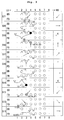
- Figs. 2 to 4 are knitting step diagrams for forming the set-up portion 101 with a series of knitting yarn fed from one yarn feeder.
- "S + number" in the left column of Figs. 2 to 4 indicates the number of the knitting step
- an arrow in right and left direction with "K” in the right column indicates moving the yarn feeder in the direction of the arrow to perform knit knitting
- an arrow in up and down or diagonal direction indicates transfer in the relevant direction.
- ⁇ in the middle column showing the actual knitting state indicates an old stitch held on the needle bed
- ⁇ indicates a stitch newly knitted in each knitting step
- ⁇ (double circle) indicates a double stitch
- V-letter indicates a widening stitch
- V indicates a yarn feeder
- a portion where knitting is actually carried out in each knitting step is shown with a thick line.
- the set-up portion 101 is formed from the left side in the plane of drawing toward the right side in the plane of drawing, and hence the rightward direction in the plane of drawing is referred to as a "forming direction RS" and the leftward direction in the plane of drawing is referred to as a "starting end direction LS".
- S0 shows a state in which stitches formed with a draw thread are held on the knitting needles 2 to 7 of the front needle bed (hereinafter, FB) as stitches of a terminating portion of a waste knitting for facilitating the knitting, and stitches formed with the draw thread are held on the knitting needles 2 to 7 of the back needle bed (hereinafter, BB).
- FB front needle bed
- BB back needle bed
- the stitch formed with the draw thread held on the knitting needle 2 of the BB is transferred to the knitting needle 1 of the opposing FB.
- the stitch held on the knitting needle 3 of the BB is overlapped with the stitch transferred to the knitting needle 1 of the FB in S1.
- the yarn feeder is moved in the forming direction RS to form a one side starting end stitch 9, which is a new stitch, following the double stitch of the knitting needle 1 of the FB, and in S4, the yarn feeder is moved toward the starting end direction LS side of the one side starting end stitch 9.
- the one side starting end stitch 9 is transferred to the knitting needle 2 of the BB.
- the stitch formed with the draw thread held on the knitting needle 2 of the FB is transferred to the knitting needle 3 of the opposing BB.
- the stitch held on the knitting needle 3 of the FB is overlapped with the stitch transferred to the knitting needle 3 of the BB in S6.
- the yarn feeder is moved in the forming direction RS to form an other side starting end stitch 10, which is a new stitch, following the double stitch of the knitting needle 3 of the BB, and in S9, the yarn feeder is moved toward the starting end direction LS side of the other side starting end stitch 10.
- the other side starting end stitch 10 is transferred to the knitting needle 2 of the FB.
- the yarn feeder is moved toward the forming direction RS up to a position beyond the knitting needle 3.
- the one side stitch 11 held on the knitting needle 2 of the BB is transferred to the knitting needle 3 (empty needle) of the FB (the first half of the step ⁇ of the present invention).
- the stitch 21 (the knitting needle 4 of the BB) formed with the draw thread adjacent in the forming direction RS side of the one side stitch 11 in S11 is transferred to the knitting needle 3 of the FB.
- one side double stitch 15 is formed on the knitting needle 3 of the FB.
- the yarn feeder is moved toward the starting end direction LS to form a new one side stitch 11 following in a wale direction of the one side double stitch 15 formed in S13 (the second half of the step ⁇ of the present invention), and a one side widening stitch 13 in form of a pickup stitch is formed on the knitting needle 2 of the BB (the step ⁇ of the present invention).
- the one side double stitch 15 includes the one side stitch 11 of S11, and hence the new one side stitch 11 formed in S14 is a front stitch following in the wale direction of the existing one side stitch 11 in S11.
- the knitting needle on which the one side widening stitch 13 is formed is a knitting needle that became an empty needle after moving the one side stitch 11 in the forming direction RS in S12.
- the knitting yarn extending from the yarn feeder crosses the FB side of the one side stitch 11 in S12, and the new one side stitch 11 formed in S14 is pulled out from the BB side to the FB side (configuration of claim 3).
- the effects involved in such arrangement of the knitting yarn will be described later.
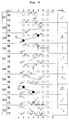
- the yarn feeder is moved toward the forming direction RS up to the position beyond the knitting needle 4.
- the new one side stitch 11 formed in S14 is transferred to the knitting needle 3 of the BB in S16.
- the other side stitch 12 held on the knitting needle 2 of the FB is transferred to the knitting needle 4 (empty needle) of the BB (the first half of the step ⁇ of the present invention).
- the stitch 22 (the knitting needle 4 of the FB) formed with the draw thread adjacent in the forming direction RS of the other side stitch 12 in S16 is transferred to the knitting needle 4 of the BB.
- other side double stitch 16 is formed on the knitting needle 4 of the BB.
- the yarn feeder is moved toward the starting end direction LS to form a new other side stitch 12 following in the wale direction of the other side double stitch 16 formed in S18 (the second half of the step ⁇ of the present invention), and then an other side widening stitch 14 in form of a pickup stitch is formed on the knitting needle 2 of the FB (the step ⁇ of the present invention).
- the other side double stitch 16 includes the other side stitch 12 of S16, and hence the new other side stitch 12 formed in S19 is a front stitch following in the wale direction of the existing other side stitch 12 in S16.
- the knitting needle on which the other side widening stitch 14 is formed is a knitting needle that became an empty needle after moving the other side stitch 12 in S17.
- the knitting yarn extending from the yarn feeder crosses the BB side of the other side stitch 12 in S17, and the new other side stitch 12 formed in S19 is pulled out from the FB side to the BB side (configuration of claim 3).
- the effects involved in such an arrangement of the knitting yarn will be described later.
- the yarn feeder is moved toward the forming direction RS to a position beyond the knitting needle 4.
- the new other side stitch 12 formed in S19 is transferred to the knitting needle 3 of the FB.
- one side double stitch 15 in which the one side stitch 11 and the stitch 21 formed with the draw thread are overlapped is formed with the knitting needle 4 (empty needle) of the FB, in a manner similar to S12 and S13 of Fig. 3 .
- next S24 and S25 knitting different from S14 and S15 of Fig. 3 is performed.
- the yarn feeder is moved toward the starting end direction LS to form a new one side stitch 11 following in the wale direction of the one side double stitch 15 held on the knitting needle 4 of the FB (the second half of the step ⁇ of the present invention).
- a one side additional stitch 17 following in the wale direction of the one side widening stitch 13 formed on the knitting needle 2 of the BB in S14 of Fig. 3 is formed (the step ⁇ ' of the present invention).
- the yarn feeder is moved toward the forming direction RS to form an one side widening stitch 13 on the knitting needle 3 of the BB (the step P of the present invention), and in S26, the new one side stitch 11 formed in S24 is transferred from the knitting needle 4 of the FB to the knitting needle 4 of the BB. In S25, the yarn feeder is moved to a position beyond the knitting needle 5.
- the yarn feeder is moved toward the forming direction RS to form an other side widening stitch 14 on the knitting needle 3 of the FB (the step ⁇ of the present invention), and in S31, the new other side stitch 12 formed in S29 is transferred from the knitting needle 5 of the BB to the knitting needle 4 of the FB. In S30, the yarn feeder is moved to the position beyond the knitting needle 5.
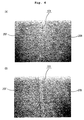
- the set-up portion 101 shown in the loop diagram of Fig. 5 and in the photograph of Fig. 6 can be knitted as a result.
- the near side in the plane of drawing of Fig. 5 corresponds to the inner side of the skirt 100 ( Fig. 8 ), the far side in the plane of drawing corresponds to the outer side of the skirt 100, and the stitches formed with the draw thread are omitted.
- the state of the stitches shown in the loop diagram of Fig. 5 traces back the path of the knitting yarn, and is slightly different from the state of the stitches in the actual knitted fabric.
- the set-up portion 101 is formed by a series of units ⁇ respectively formed in the order of one side stitch 11 ⁇ one side additional stitch 17 ⁇ one side widening stitch 13 ⁇ other side stitch 12 ⁇ other side additional stitch 18 ⁇ other side widening stitch 14.
- the adjoining units ⁇ are connected by forming the one side stitch 11 and the other side stitch 13 of the n th (second or higher) units ⁇ with respect to the one side stitch 11 and the other side stitch 13 of the n-1 th unit ⁇ .
- the stitches 11, 17, 13, 12, 18, 14 formed in a predetermined order moderately restrict the respective movement, and thus the stretchability of the set-up portion 101 of the first embodiment is suppressed compared to the conventional set-up portion.
- the knitting yarn connecting the n th one side stitch 11 and the n-1 th other side widening stitch 14 crosses the far side in the plane of drawing of the n-1 th one side stitch 11, and the n th one side stitch 11 is pulled out from the near side to the far side in the plane of drawing. That is, the knitting yarn winds around the n-1 th one side stitch 11, and the knitting yarn causes the n-1 th one side stitch 11 to be rotated a half turn in the direction of a dotted line arrow.
- the one side stitch 11 inclined to the stitch of the one side knitted fabric portion 20B is drawn to the near side in the plane of drawing (i.e., the inner side of the skirt 100) so as to be invisible from the outer side of the skirt 100 (see Fig. 6A ).
- the one side stitch 11 drawn to the inner side of the skirt 100 lines in the forming direction of the set-up portion 101 (see Fig. 6B ).
- a cross-over yarn of the set-up portion 101 crossed between the one side knitted fabric portion 20B and the other side knitted fabric portion 20F is arranged as if it is a stitch, so that the set-up portion 101 is less likely to stand out and a hole is less likely to form in the set-up portion 101, as shown in Fig. 6A .
- the set-up portion 101 may be knitted without forming the one side additional stitch 17 and the other side additional stitch 18 shown in the knitting step diagram of Fig. 4 and the loop diagram of Fig. 5 .
- the knitting same as Figs. 2 and 3 of the first embodiment may be performed, and the knitting similar to S11 to S21 may be repeated after S21 of Fig. 3 .
- the set-up portion 101 in which the stretchability is suppressed compared to the conventional set-up portion can also be knitted with the knitting method of the knitted fabric of the second embodiment.
- the set-up portion may be formed with the knitting method of the knitted fabric according to the present invention from a state in which the knitting yarn is not hanged on the needle beds at all (i.e., a state in which there is no stitch formed with the draw thread in S0 of Fig. 2 ).
- two widening stitches to become the one side stitch and the other side stitch are formed on an arbitrary knitting needle of the FB and the knitting needle of the BB at the position substantially facing the knitting needle of the FB.
- the widening stitch of the FB is moved toward the forming direction RS and then a new one side stitch following in the wale direction of the widening stitch is formed.
- a new widening stitch is then formed on the knitting needle that became an empty needle as a result of the movement of the widening stitch. Similar knitting is carried out with the BB as well. Thereafter, the knitting with "moving the stitch in the forming direction" ⁇ "forming the stitch following in the wale direction of the moved stitch” ⁇ "forming the widening stitch on the empty needle obtained as a result of the movement of the stitch" as one set is alternately carried out with the FB and the BB to form the set-up portion from the state without the stitch formed with the draw thread.
- the knitted fabric to which the knitting method of the knitted fabric according to the present invention is applied is not limited to the skirt set-up from the side end shown in the first embodiment.
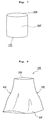
- the set-up portion may be knitted according to the knitting steps shown in the first embodiment and the circling knitting may be carried out with respect to the set-up portion to knit a tubular knitted fabric as shown in Fig. 7 .
- the set-up portion 101 is arranged at the bottom portion of the tubular knitted fabric.
- the knitting method of the knitted fabric according to the present invention can also be applied to the knitting of a sweater or the like set up from the side.
Landscapes
- Engineering & Computer Science (AREA)
- Textile Engineering (AREA)
- Knitting Of Fabric (AREA)
Claims (5)
- Procédé de tricotage d'un tissu tricoté (100) pour tricoter une portion de mise en place (101) connectant une portion de tissu tricoté d'un premier côté (20B), qui est principalement tricotée sur une première fonture, et une portion de tissu tricoté d'un autre côté (20F), qui est principalement tricotée sur une autre fonture, en utilisant une machine à tricoter à plat comprenant au moins une fonture avant (FB) et une fonture arrière (BB), dans lequel au moins l'une des fontures avant et arrière (FB, BB) peut être déplacée dans une direction transversale et des mailles peuvent être transférées entre les fontures avant et arrière (FB, BB) ;
en supposant qu'une direction dans laquelle la portion de mise en place (101) est formée séquentiellement dans une direction longitudinale des fontures (FB, BB) est une direction de formation (RS) et qu'une direction opposée est une direction d'extrémité de départ (LS), le procédé de tricotage est caractérisé par la formation de la portion de mise en place (101) en répétant :une étape 0 consistant à former une maille d'un premier côté (9, 11) sur une première fonture (FB, BB) et à former une maille d'un autre côté (10, 12) sur une autre fonture (BB, FB) ;une étape α consistant à transférer la maille du premier côté (11) maintenue sur la première fonture (FB, BB) vers une aiguille à tricoter (1 à 8) dans la direction de formation (RS), et à former une nouvelle maille du premier côté (11) à la suite dans une direction de colonne de mailles de la maille déplacée du premier côté (11) ;une étape β consistant à former une maille d'élargissement du premier côté (13) sur une aiguille vide (1 à 8) sur le côté de la direction d'extrémité de départ (LS) de la nouvelle maille du premier côté (11) formée dans l'étape α ;une étape γ consistant à transférer la maille de l'autre côté (12) maintenue sur l'autre fonture (BB, FB) vers une aiguille à tricoter (1 à 8) dans la direction de formation (RS) et à former une nouvelle maille de l'autre côté (12) à la suite dans une direction de colonne de mailles de la maille déplacée de l'autre côté (12) après l'étape β ; etune étape δ consistant à former une maille d'élargissement de l'autre côté (14) sur une aiguille vide (1 à 8) sur le côté de la direction d'extrémité de départ (LS) de la nouvelle maille de l'autre côté (12) formée dans l'étape γ,ce par quoi les étapes α à δ sont réalisées consécutivement avec un même distributeur de fil. - Procédé de tricotage d'un tissu tricoté (100) selon la revendication 1, caractérisé par :une étape α' consistant à former une maille additionnelle du premier côté (17) à la suite dans une direction de colonne de mailles de la maille d'élargissement du premier côté (13) formée dans une étape β de rang n-1 entre l'étape α de rang n et l'étape β ou après l'étape β de rang n ; etune étape γ' consistant à former une maille additionnelle de l'autre côté (18) à la suite dans une direction de colonne de mailles de la maille d'élargissement de l'autre côté (14) formée dans une étape δ de rang n-1 entre l'étape γ de rang n et l'étape δ ou après l'étape δ de rang n.
- Procédé de tricotage d'un tissu tricoté (100) selon la revendication 1 ou 2, caractérisé en ce que,
lors de la formation de la nouvelle maille du premier côté (11) à la suite dans la direction de colonne de mailles de la maille existante du premier côté (11) dans l'étape α, le distributeur de fil pour fournir le fil à tricoter aux fontures (FB, BB) est déplacé vers une position dépassant la maille existante du premier côté (11) de sorte que le fil à tricoter s'étendant à partir du distributeur de fil traverse la maille existante du premier côté (11), puis le distributeur de fil est inversé de sorte que le fil à tricoter est tiré à partir d'un côté opposé au côté où le fil à tricoter traverse la maille existante du premier côté (11) vers le côté où le fil à tricoter traverse pour former la nouvelle maille du premier côté (11) ; et
lors de la formation de la nouvelle maille de l'autre côté (12) à la suite dans la direction de colonne de mailles de la maille existante de l'autre côté (12) dans l'étape γ, le fil à tricoter est déplacé vers une position dépassant la maille existante de l'autre côté (12) de sorte que le fil à tricoter s'étendant à partir du distributeur de fil traverse la maille existante de l'autre côté (12), puis le distributeur de fil est inversé de sorte que le fil à tricoter est tiré à partir d'un côté opposé vers le côté où le fil à tricoter traverse la maille existante de l'autre côté (12) vers le côté où le fil à tricoter traverse pour former la nouvelle maille de l'autre côté (12). - Tissu tricoté comprenant une portion de mise en place (101), et une portion de tissu tricoté d'un premier côté (20B) et une portion de tissu tricoté d'un autre côté (20F) divergeant dans des directions différentes à partir de la portion de mise en place (101), le tissu tricoté étant tricoté en utilisant une machine à tricoter à plat comprenant au moins une fonture avant (FB) et une fonture arrière (BB), dans laquelle au moins l'une des fontures avant et arrière (FB, BB) peut être déplacée dans une direction transversale et des mailles peuvent être transférées entre les fontures avant et arrière (FB, BB) ;
caractérisé en ce que,
la portion de mise en place (101) comprend une pluralité d'unités ω tricotées de façon continue avec un seul le fil à tricoter, chaque unité ω comprenant,
une maille d'un premier côté (11) inclinée vers une maille de la portion de tissu tricoté du premier côté (20B),
une maille d'élargissement du premier côté (13) tricotée après la maille du premier côté (11) et agencée sur un côté opposé à la direction dans laquelle la maille du premier côté (11) est inclinée de la maille du premier côté (11),
une maille de l'autre côté (12) tricotée après la maille d'élargissement du premier côté (13) et inclinée vers une maille de la portion de tissu tricoté de l'autre côté (20F), et
une maille d'élargissement de l'autre côté (14) tricotée après la maille de l'autre côté (12) et agencée sur un côté opposé à la direction dans laquelle la maille de l'autre côté (12) est inclinée de la maille de l'autre côté (12) ; dans lequel
la maille du premier côté (11) de l'unité ω de rang n est formée dans une direction de colonne de mailles par rapport à la maille du premier côté (11) de l'unité ω de rang n-1 ;
la maille de l'autre côté (12) de l'unité ω de rang n est formée dans une direction de colonne de mailles par rapport à la maille de l'autre côté (12) de l'unité ω de rang n-1 ;
une maille de la portion de tissu tricoté du premier côté (20B) est formée dans la direction de colonne de mailles de la maille d'élargissement du premier côté (13) ; et
une maille de la portion de tissu tricoté de l'autre côté (20F) est formée dans la direction de colonne de mailles de la maille d'élargissement de l'autre côté (14),
ce par quoi les mailles de la portion de mise en place (101) sont tricotées de façon consécutive avec un même distributeur de fil. - Tissu tricoté (100) selon la revendication 4, caractérisé en ce que l'unité ω comprend en outre,
une maille additionnelle du premier côté (17) formée entre la maille d'élargissement du premier côté (13) et la maille de la portion de tissu tricoté du premier côté (20B) ; et
une maille additionnelle de l'autre côté (18) formée entre la maille d'élargissement de l'autre côté (14) et la maille de la portion de tissu tricoté de l'autre côté (20F).
Applications Claiming Priority (1)
| Application Number | Priority Date | Filing Date | Title |
|---|---|---|---|
| JP2011143542A JP5736250B2 (ja) | 2011-06-28 | 2011-06-28 | 編地の編成方法、および編地 |
Publications (3)
| Publication Number | Publication Date |
|---|---|
| EP2540887A2 EP2540887A2 (fr) | 2013-01-02 |
| EP2540887A3 EP2540887A3 (fr) | 2015-05-27 |
| EP2540887B1 true EP2540887B1 (fr) | 2016-06-08 |
Family
ID=46466058
Family Applications (1)
| Application Number | Title | Priority Date | Filing Date |
|---|---|---|---|
| EP12004811.1A Active EP2540887B1 (fr) | 2011-06-28 | 2012-06-27 | Procédé pour tricoter une étoffe et étoffe tricotée |
Country Status (4)
| Country | Link |
|---|---|
| EP (1) | EP2540887B1 (fr) |
| JP (1) | JP5736250B2 (fr) |
| KR (1) | KR101356436B1 (fr) |
| CN (1) | CN102851866B (fr) |
Families Citing this family (8)
| Publication number | Priority date | Publication date | Assignee | Title |
|---|---|---|---|---|
| JP5922903B2 (ja) * | 2011-10-03 | 2016-05-24 | 株式会社島精機製作所 | 編地の編成方法 |
| TWI585254B (zh) * | 2013-04-23 | 2017-06-01 | 島精機製作所股份有限公司 | 編織物之編織方法 |
| JP2015110849A (ja) * | 2013-12-06 | 2015-06-18 | 株式会社島精機製作所 | 編地の編成方法 |
| JP6347678B2 (ja) * | 2014-06-25 | 2018-06-27 | 株式会社島精機製作所 | 編出し方法 |
| JP6223308B2 (ja) * | 2014-09-18 | 2017-11-01 | 株式会社島精機製作所 | 編地の編成方法 |
| DE102018210887A1 (de) | 2017-07-06 | 2019-01-10 | Shima Seiki Mfg., Ltd. | Gestrick-Strickverfahren und Gestrick |
| JP6738791B2 (ja) * | 2017-07-06 | 2020-08-12 | 株式会社島精機製作所 | 編地の編成方法、および編地 |
| JP6932076B2 (ja) | 2017-12-21 | 2021-09-08 | 株式会社島精機製作所 | 編地の編成方法 |
Family Cites Families (16)
| Publication number | Priority date | Publication date | Assignee | Title |
|---|---|---|---|---|
| JPH0473245A (ja) * | 1990-07-13 | 1992-03-09 | Shima Seiki Mfg Ltd | 編出し方法及びその編地 |
| US5628209A (en) * | 1994-09-01 | 1997-05-13 | Shima Seiki Manufacturing Ltd. | Method of forming a knot on a flat knitting machine |
| JP3044368B2 (ja) * | 1995-12-28 | 2000-05-22 | 株式会社島精機製作所 | 伏せ目方法及び伏せ目方法により処理された編地、ならびに伏せ目方法を発生させるためのcad装置 |
| JP3126315B2 (ja) * | 1996-10-29 | 2001-01-22 | 株式会社島精機製作所 | 2×1ゴム編み組織を有する筒状編地の編成方法 |
| DE19710896A1 (de) * | 1997-03-15 | 1998-09-17 | Stoll & Co H | Verfahren zur Herstellung eines Gestrickes auf einer Flachstrickmaschine |
| CN1277968C (zh) * | 2001-03-02 | 2006-10-04 | 株式会社岛精机制作所 | 具有开口部的针织物及其编织方法 |
| JP2002339202A (ja) * | 2001-05-10 | 2002-11-27 | Shima Seiki Mfg Ltd | リブ編地の内増やし方法及び当該方法で内増やしされたリブ編地 |
| WO2002092895A1 (fr) * | 2001-05-11 | 2002-11-21 | Shima Seiki Manufacturing, Ltd. | Procede de tricotage sur machine de tricotage rectiligne, et programme de tricotage |
| CN1292114C (zh) * | 2001-06-12 | 2006-12-27 | 株式会社岛精机制作所 | 具有新型起口构造的针织物及其编织方法 |
| DE50113173D1 (de) * | 2001-08-28 | 2007-12-06 | Stoll & Co H | Verfahren zur Bildung von sich über mehrere Nadeln erstreckenden Maschen |
| JP4503352B2 (ja) * | 2004-05-25 | 2010-07-14 | 株式会社島精機製作所 | 編地の編成方法と編地並びに編成プログラム |
| CN101395312B (zh) * | 2006-02-28 | 2011-06-15 | 株式会社岛精机制作所 | 形成放针线圈的方法及在针织物的编织宽度方向端部的内侧形成放针线圈的针织物 |
| KR101209645B1 (ko) * | 2006-03-20 | 2012-12-07 | 가부시키가이샤 시마세이키 세이사쿠쇼 | 편성포의 편성방법 및 디자인 장치 |
| JP5603779B2 (ja) * | 2008-12-26 | 2014-10-08 | 株式会社島精機製作所 | 内増やし方法、および編地 |
| WO2011004694A1 (fr) * | 2009-07-09 | 2011-01-13 | 株式会社島精機製作所 | Tricot comportant des manches et un corps, et procédé de tricotage associé |
| JP2012251262A (ja) * | 2011-06-03 | 2012-12-20 | Shima Seiki Mfg Ltd | 編地の編成方法、および編地 |
-
2011
- 2011-06-28 JP JP2011143542A patent/JP5736250B2/ja active Active
-
2012
- 2012-06-01 KR KR1020120059045A patent/KR101356436B1/ko active Active
- 2012-06-27 EP EP12004811.1A patent/EP2540887B1/fr active Active
- 2012-06-27 CN CN201210216402.6A patent/CN102851866B/zh active Active
Also Published As
| Publication number | Publication date |
|---|---|
| EP2540887A2 (fr) | 2013-01-02 |
| KR20130002259A (ko) | 2013-01-07 |
| JP2013011031A (ja) | 2013-01-17 |
| CN102851866A (zh) | 2013-01-02 |
| JP5736250B2 (ja) | 2015-06-17 |
| EP2540887A3 (fr) | 2015-05-27 |
| KR101356436B1 (ko) | 2014-01-29 |
| CN102851866B (zh) | 2014-07-16 |
Similar Documents
| Publication | Publication Date | Title |
|---|---|---|
| EP2540887B1 (fr) | Procédé pour tricoter une étoffe et étoffe tricotée | |
| EP2530197A2 (fr) | Procédé pour tricoter une étoffe et étoffe tricotée | |
| EP2460919B1 (fr) | Procédé de jonction pour étoffe tricotée | |
| EP2226417A1 (fr) | Procédé de tricotage de tissu, et tissu | |
| EP2634299B1 (fr) | Procédé de tricotage d'une étoffe tricotée avec frange | |
| EP2465983B1 (fr) | Procédé de formation de tissu | |
| EP2881507B1 (fr) | Procédé pour tricoter un tissu tricoté | |
| CN102086560B (zh) | 针织物的编织方法和针织物 | |
| EP2530196B1 (fr) | Procédé pour tricoter une étoffe avec un trou et étoffe tricotée | |
| CN102191616B (zh) | V领尖端部的编织方法及具有v领的编织物 | |
| JPWO2001057299A1 (ja) | ニットウエア編成方法 | |
| EP2385160B1 (fr) | Procédé pour tricoter une étoffe tricotée tubulaire | |
| EP1211341B1 (fr) | Procede de couture d'ourlets avec une excellente aptitude a l'etirage | |
| EP2581479A1 (fr) | Procédé de jonction pour étoffe tricotée et étoffe tricotée | |
| EP2418310B1 (fr) | Procédé de jonction de pièces de tricot adjacentes et tissu tricoté | |
| EP2410085B1 (fr) | Procédé de tricotage de tissu tricoté et tissu tricoté | |
| JP5349357B2 (ja) | プレーティング編成方法 | |
| EP2495361A1 (fr) | Procédé pour tricoter une étoffe tricotée tubulaire et étoffe tricotée tubulaire | |
| JP5695847B2 (ja) | 内増やし方法、および編地 | |
| EP2431510B1 (fr) | Procédé de tricotage d'un tissu tubulaire, et tissu tubulaire | |
| EP2463420A2 (fr) | Procédé de remaillage d'étoffe tricotée et étoffe tricotée | |
| EP2281933A1 (fr) | Procédé pour tricoter un tissu tricoté avec mailles chevauchées, et tissu tricoté | |
| JP2015021211A (ja) | リボンを備える編地の編成方法、および編地 |
Legal Events
| Date | Code | Title | Description |
|---|---|---|---|
| PUAI | Public reference made under article 153(3) epc to a published international application that has entered the european phase |
Free format text: ORIGINAL CODE: 0009012 |
|
| AK | Designated contracting states |
Kind code of ref document: A2 Designated state(s): AL AT BE BG CH CY CZ DE DK EE ES FI FR GB GR HR HU IE IS IT LI LT LU LV MC MK MT NL NO PL PT RO RS SE SI SK SM TR |
|
| AX | Request for extension of the european patent |
Extension state: BA ME |
|
| PUAL | Search report despatched |
Free format text: ORIGINAL CODE: 0009013 |
|
| AK | Designated contracting states |
Kind code of ref document: A3 Designated state(s): AL AT BE BG CH CY CZ DE DK EE ES FI FR GB GR HR HU IE IS IT LI LT LU LV MC MK MT NL NO PL PT RO RS SE SI SK SM TR |
|
| AX | Request for extension of the european patent |
Extension state: BA ME |
|
| RIC1 | Information provided on ipc code assigned before grant |
Ipc: D04B 1/22 20060101AFI20150423BHEP |
|
| 17P | Request for examination filed |
Effective date: 20151125 |
|
| RBV | Designated contracting states (corrected) |
Designated state(s): AL AT BE BG CH CY CZ DE DK EE ES FI FR GB GR HR HU IE IS IT LI LT LU LV MC MK MT NL NO PL PT RO RS SE SI SK SM TR |
|
| GRAP | Despatch of communication of intention to grant a patent |
Free format text: ORIGINAL CODE: EPIDOSNIGR1 |
|
| INTG | Intention to grant announced |
Effective date: 20160111 |
|
| GRAS | Grant fee paid |
Free format text: ORIGINAL CODE: EPIDOSNIGR3 |
|
| GRAA | (expected) grant |
Free format text: ORIGINAL CODE: 0009210 |
|
| AK | Designated contracting states |
Kind code of ref document: B1 Designated state(s): AL AT BE BG CH CY CZ DE DK EE ES FI FR GB GR HR HU IE IS IT LI LT LU LV MC MK MT NL NO PL PT RO RS SE SI SK SM TR |
|
| REG | Reference to a national code |
Ref country code: GB Ref legal event code: FG4D |
|
| REG | Reference to a national code |
Ref country code: CH Ref legal event code: EP |
|
| REG | Reference to a national code |
Ref country code: IE Ref legal event code: FG4D |
|
| REG | Reference to a national code |
Ref country code: AT Ref legal event code: REF Ref document number: 805324 Country of ref document: AT Kind code of ref document: T Effective date: 20160715 |
|
| REG | Reference to a national code |
Ref country code: DE Ref legal event code: R096 Ref document number: 602012019299 Country of ref document: DE |
|
| REG | Reference to a national code |
Ref country code: LT Ref legal event code: MG4D |
|
| REG | Reference to a national code |
Ref country code: NL Ref legal event code: MP Effective date: 20160608 |
|
| PG25 | Lapsed in a contracting state [announced via postgrant information from national office to epo] |
Ref country code: NO Free format text: LAPSE BECAUSE OF FAILURE TO SUBMIT A TRANSLATION OF THE DESCRIPTION OR TO PAY THE FEE WITHIN THE PRESCRIBED TIME-LIMIT Effective date: 20160908 Ref country code: FI Free format text: LAPSE BECAUSE OF FAILURE TO SUBMIT A TRANSLATION OF THE DESCRIPTION OR TO PAY THE FEE WITHIN THE PRESCRIBED TIME-LIMIT Effective date: 20160608 Ref country code: LT Free format text: LAPSE BECAUSE OF FAILURE TO SUBMIT A TRANSLATION OF THE DESCRIPTION OR TO PAY THE FEE WITHIN THE PRESCRIBED TIME-LIMIT Effective date: 20160608 |
|
| REG | Reference to a national code |
Ref country code: AT Ref legal event code: MK05 Ref document number: 805324 Country of ref document: AT Kind code of ref document: T Effective date: 20160608 |
|
| PG25 | Lapsed in a contracting state [announced via postgrant information from national office to epo] |
Ref country code: GR Free format text: LAPSE BECAUSE OF FAILURE TO SUBMIT A TRANSLATION OF THE DESCRIPTION OR TO PAY THE FEE WITHIN THE PRESCRIBED TIME-LIMIT Effective date: 20160909 Ref country code: NL Free format text: LAPSE BECAUSE OF FAILURE TO SUBMIT A TRANSLATION OF THE DESCRIPTION OR TO PAY THE FEE WITHIN THE PRESCRIBED TIME-LIMIT Effective date: 20160608 Ref country code: RS Free format text: LAPSE BECAUSE OF FAILURE TO SUBMIT A TRANSLATION OF THE DESCRIPTION OR TO PAY THE FEE WITHIN THE PRESCRIBED TIME-LIMIT Effective date: 20160608 Ref country code: LV Free format text: LAPSE BECAUSE OF FAILURE TO SUBMIT A TRANSLATION OF THE DESCRIPTION OR TO PAY THE FEE WITHIN THE PRESCRIBED TIME-LIMIT Effective date: 20160608 Ref country code: SE Free format text: LAPSE BECAUSE OF FAILURE TO SUBMIT A TRANSLATION OF THE DESCRIPTION OR TO PAY THE FEE WITHIN THE PRESCRIBED TIME-LIMIT Effective date: 20160608 Ref country code: HR Free format text: LAPSE BECAUSE OF FAILURE TO SUBMIT A TRANSLATION OF THE DESCRIPTION OR TO PAY THE FEE WITHIN THE PRESCRIBED TIME-LIMIT Effective date: 20160608 Ref country code: ES Free format text: LAPSE BECAUSE OF FAILURE TO SUBMIT A TRANSLATION OF THE DESCRIPTION OR TO PAY THE FEE WITHIN THE PRESCRIBED TIME-LIMIT Effective date: 20160608 |
|
| PG25 | Lapsed in a contracting state [announced via postgrant information from national office to epo] |
Ref country code: BE Free format text: LAPSE BECAUSE OF NON-PAYMENT OF DUE FEES Effective date: 20160630 |
|
| PG25 | Lapsed in a contracting state [announced via postgrant information from national office to epo] |
Ref country code: IS Free format text: LAPSE BECAUSE OF FAILURE TO SUBMIT A TRANSLATION OF THE DESCRIPTION OR TO PAY THE FEE WITHIN THE PRESCRIBED TIME-LIMIT Effective date: 20161008 Ref country code: EE Free format text: LAPSE BECAUSE OF FAILURE TO SUBMIT A TRANSLATION OF THE DESCRIPTION OR TO PAY THE FEE WITHIN THE PRESCRIBED TIME-LIMIT Effective date: 20160608 Ref country code: SK Free format text: LAPSE BECAUSE OF FAILURE TO SUBMIT A TRANSLATION OF THE DESCRIPTION OR TO PAY THE FEE WITHIN THE PRESCRIBED TIME-LIMIT Effective date: 20160608 Ref country code: RO Free format text: LAPSE BECAUSE OF FAILURE TO SUBMIT A TRANSLATION OF THE DESCRIPTION OR TO PAY THE FEE WITHIN THE PRESCRIBED TIME-LIMIT Effective date: 20160608 Ref country code: CZ Free format text: LAPSE BECAUSE OF FAILURE TO SUBMIT A TRANSLATION OF THE DESCRIPTION OR TO PAY THE FEE WITHIN THE PRESCRIBED TIME-LIMIT Effective date: 20160608 |
|
| REG | Reference to a national code |
Ref country code: CH Ref legal event code: PL |
|
| PG25 | Lapsed in a contracting state [announced via postgrant information from national office to epo] |
Ref country code: PT Free format text: LAPSE BECAUSE OF FAILURE TO SUBMIT A TRANSLATION OF THE DESCRIPTION OR TO PAY THE FEE WITHIN THE PRESCRIBED TIME-LIMIT Effective date: 20161010 Ref country code: AT Free format text: LAPSE BECAUSE OF FAILURE TO SUBMIT A TRANSLATION OF THE DESCRIPTION OR TO PAY THE FEE WITHIN THE PRESCRIBED TIME-LIMIT Effective date: 20160608 Ref country code: PL Free format text: LAPSE BECAUSE OF FAILURE TO SUBMIT A TRANSLATION OF THE DESCRIPTION OR TO PAY THE FEE WITHIN THE PRESCRIBED TIME-LIMIT Effective date: 20160608 Ref country code: SM Free format text: LAPSE BECAUSE OF FAILURE TO SUBMIT A TRANSLATION OF THE DESCRIPTION OR TO PAY THE FEE WITHIN THE PRESCRIBED TIME-LIMIT Effective date: 20160608 Ref country code: BE Free format text: LAPSE BECAUSE OF FAILURE TO SUBMIT A TRANSLATION OF THE DESCRIPTION OR TO PAY THE FEE WITHIN THE PRESCRIBED TIME-LIMIT Effective date: 20160608 |
|
| REG | Reference to a national code |
Ref country code: DE Ref legal event code: R097 Ref document number: 602012019299 Country of ref document: DE |
|
| REG | Reference to a national code |
Ref country code: IE Ref legal event code: MM4A |
|
| PG25 | Lapsed in a contracting state [announced via postgrant information from national office to epo] |
Ref country code: MC Free format text: LAPSE BECAUSE OF FAILURE TO SUBMIT A TRANSLATION OF THE DESCRIPTION OR TO PAY THE FEE WITHIN THE PRESCRIBED TIME-LIMIT Effective date: 20160608 |
|
| PLBE | No opposition filed within time limit |
Free format text: ORIGINAL CODE: 0009261 |
|
| STAA | Information on the status of an ep patent application or granted ep patent |
Free format text: STATUS: NO OPPOSITION FILED WITHIN TIME LIMIT |
|
| PG25 | Lapsed in a contracting state [announced via postgrant information from national office to epo] |
Ref country code: LI Free format text: LAPSE BECAUSE OF NON-PAYMENT OF DUE FEES Effective date: 20160630 Ref country code: FR Free format text: LAPSE BECAUSE OF NON-PAYMENT OF DUE FEES Effective date: 20160808 Ref country code: CH Free format text: LAPSE BECAUSE OF NON-PAYMENT OF DUE FEES Effective date: 20160630 |
|
| REG | Reference to a national code |
Ref country code: FR Ref legal event code: ST Effective date: 20170329 |
|
| 26N | No opposition filed |
Effective date: 20170309 |
|
| GBPC | Gb: european patent ceased through non-payment of renewal fee |
Effective date: 20160908 |
|
| PG25 | Lapsed in a contracting state [announced via postgrant information from national office to epo] |
Ref country code: IE Free format text: LAPSE BECAUSE OF NON-PAYMENT OF DUE FEES Effective date: 20160627 Ref country code: SI Free format text: LAPSE BECAUSE OF FAILURE TO SUBMIT A TRANSLATION OF THE DESCRIPTION OR TO PAY THE FEE WITHIN THE PRESCRIBED TIME-LIMIT Effective date: 20160608 Ref country code: DK Free format text: LAPSE BECAUSE OF FAILURE TO SUBMIT A TRANSLATION OF THE DESCRIPTION OR TO PAY THE FEE WITHIN THE PRESCRIBED TIME-LIMIT Effective date: 20160608 |
|
| PG25 | Lapsed in a contracting state [announced via postgrant information from national office to epo] |
Ref country code: GB Free format text: LAPSE BECAUSE OF NON-PAYMENT OF DUE FEES Effective date: 20160908 |
|
| PG25 | Lapsed in a contracting state [announced via postgrant information from national office to epo] |
Ref country code: CY Free format text: LAPSE BECAUSE OF FAILURE TO SUBMIT A TRANSLATION OF THE DESCRIPTION OR TO PAY THE FEE WITHIN THE PRESCRIBED TIME-LIMIT Effective date: 20160608 Ref country code: HU Free format text: LAPSE BECAUSE OF FAILURE TO SUBMIT A TRANSLATION OF THE DESCRIPTION OR TO PAY THE FEE WITHIN THE PRESCRIBED TIME-LIMIT; INVALID AB INITIO Effective date: 20120627 |
|
| PG25 | Lapsed in a contracting state [announced via postgrant information from national office to epo] |
Ref country code: MK Free format text: LAPSE BECAUSE OF FAILURE TO SUBMIT A TRANSLATION OF THE DESCRIPTION OR TO PAY THE FEE WITHIN THE PRESCRIBED TIME-LIMIT Effective date: 20160608 Ref country code: LU Free format text: LAPSE BECAUSE OF NON-PAYMENT OF DUE FEES Effective date: 20160627 Ref country code: MT Free format text: LAPSE BECAUSE OF NON-PAYMENT OF DUE FEES Effective date: 20160630 Ref country code: TR Free format text: LAPSE BECAUSE OF FAILURE TO SUBMIT A TRANSLATION OF THE DESCRIPTION OR TO PAY THE FEE WITHIN THE PRESCRIBED TIME-LIMIT Effective date: 20160608 |
|
| PG25 | Lapsed in a contracting state [announced via postgrant information from national office to epo] |
Ref country code: BG Free format text: LAPSE BECAUSE OF FAILURE TO SUBMIT A TRANSLATION OF THE DESCRIPTION OR TO PAY THE FEE WITHIN THE PRESCRIBED TIME-LIMIT Effective date: 20160608 |
|
| PG25 | Lapsed in a contracting state [announced via postgrant information from national office to epo] |
Ref country code: AL Free format text: LAPSE BECAUSE OF FAILURE TO SUBMIT A TRANSLATION OF THE DESCRIPTION OR TO PAY THE FEE WITHIN THE PRESCRIBED TIME-LIMIT Effective date: 20160608 |
|
| PGFP | Annual fee paid to national office [announced via postgrant information from national office to epo] |
Ref country code: DE Payment date: 20250402 Year of fee payment: 14 |
|
| PGFP | Annual fee paid to national office [announced via postgrant information from national office to epo] |
Ref country code: IT Payment date: 20250522 Year of fee payment: 14 |