EP2540468B1 - Gussform - Google Patents
Gussform Download PDFInfo
- Publication number
- EP2540468B1 EP2540468B1 EP12186218.9A EP12186218A EP2540468B1 EP 2540468 B1 EP2540468 B1 EP 2540468B1 EP 12186218 A EP12186218 A EP 12186218A EP 2540468 B1 EP2540468 B1 EP 2540468B1
- Authority
- EP
- European Patent Office
- Prior art keywords
- mold
- casting
- mold body
- cavity
- injection port
- Prior art date
- Legal status (The legal status is an assumption and is not a legal conclusion. Google has not performed a legal analysis and makes no representation as to the accuracy of the status listed.)
- Not-in-force
Links
- 238000005266 casting Methods 0.000 title claims description 128
- 239000000463 material Substances 0.000 claims description 99
- 238000002347 injection Methods 0.000 claims description 34
- 239000007924 injection Substances 0.000 claims description 34
- 230000007246 mechanism Effects 0.000 claims description 19
- 238000010438 heat treatment Methods 0.000 claims description 16
- 229920001187 thermosetting polymer Polymers 0.000 claims description 11
- 125000006850 spacer group Chemical group 0.000 description 46
- 238000000034 method Methods 0.000 description 16
- 239000003822 epoxy resin Substances 0.000 description 11
- 239000002184 metal Substances 0.000 description 11
- 229920000647 polyepoxide Polymers 0.000 description 11
- 238000001879 gelation Methods 0.000 description 9
- 239000004020 conductor Substances 0.000 description 8
- 239000012212 insulator Substances 0.000 description 8
- 238000004519 manufacturing process Methods 0.000 description 7
- 229920005989 resin Polymers 0.000 description 7
- 239000011347 resin Substances 0.000 description 7
- 238000001723 curing Methods 0.000 description 6
- 239000007787 solid Substances 0.000 description 6
- 238000009413 insulation Methods 0.000 description 5
- 229910018503 SF6 Inorganic materials 0.000 description 4
- 238000006243 chemical reaction Methods 0.000 description 3
- SFZCNBIFKDRMGX-UHFFFAOYSA-N sulfur hexafluoride Chemical compound FS(F)(F)(F)(F)F SFZCNBIFKDRMGX-UHFFFAOYSA-N 0.000 description 3
- 229960000909 sulfur hexafluoride Drugs 0.000 description 3
- 230000015572 biosynthetic process Effects 0.000 description 2
- IISBACLAFKSPIT-UHFFFAOYSA-N bisphenol A Chemical compound C=1C=C(O)C=CC=1C(C)(C)C1=CC=C(O)C=C1 IISBACLAFKSPIT-UHFFFAOYSA-N 0.000 description 2
- 239000003795 chemical substances by application Substances 0.000 description 2
- 238000004132 cross linking Methods 0.000 description 2
- 239000004850 liquid epoxy resins (LERs) Substances 0.000 description 2
- 238000000465 moulding Methods 0.000 description 2
- 230000002093 peripheral effect Effects 0.000 description 2
- 150000008065 acid anhydrides Chemical class 0.000 description 1
- PNEYBMLMFCGWSK-UHFFFAOYSA-N aluminium oxide Inorganic materials [O-2].[O-2].[O-2].[Al+3].[Al+3] PNEYBMLMFCGWSK-UHFFFAOYSA-N 0.000 description 1
- 230000008901 benefit Effects 0.000 description 1
- 230000008878 coupling Effects 0.000 description 1
- 238000010168 coupling process Methods 0.000 description 1
- 238000005859 coupling reaction Methods 0.000 description 1
- 238000010891 electric arc Methods 0.000 description 1
- 238000010292 electrical insulation Methods 0.000 description 1
- WRQGPGZATPOHHX-UHFFFAOYSA-N ethyl 2-oxohexanoate Chemical compound CCCCC(=O)C(=O)OCC WRQGPGZATPOHHX-UHFFFAOYSA-N 0.000 description 1
- 239000000835 fiber Substances 0.000 description 1
- 239000000945 filler Substances 0.000 description 1
- 230000020169 heat generation Effects 0.000 description 1
- 238000001746 injection moulding Methods 0.000 description 1
- 239000011256 inorganic filler Substances 0.000 description 1
- 229910003475 inorganic filler Inorganic materials 0.000 description 1
- 238000007689 inspection Methods 0.000 description 1
- 239000007788 liquid Substances 0.000 description 1
- 230000007774 longterm Effects 0.000 description 1
- 238000002156 mixing Methods 0.000 description 1
- 239000000203 mixture Substances 0.000 description 1
- 230000004048 modification Effects 0.000 description 1
- 238000012986 modification Methods 0.000 description 1
- 230000003287 optical effect Effects 0.000 description 1
- 230000000704 physical effect Effects 0.000 description 1
- 239000004033 plastic Substances 0.000 description 1
- 239000002861 polymer material Substances 0.000 description 1
- 230000008569 process Effects 0.000 description 1
- 229920002050 silicone resin Polymers 0.000 description 1
- 239000007921 spray Substances 0.000 description 1
- 238000006467 substitution reaction Methods 0.000 description 1
- 238000001029 thermal curing Methods 0.000 description 1
- 230000007704 transition Effects 0.000 description 1
Images


Classifications
-
- B—PERFORMING OPERATIONS; TRANSPORTING
- B29—WORKING OF PLASTICS; WORKING OF SUBSTANCES IN A PLASTIC STATE IN GENERAL
- B29C—SHAPING OR JOINING OF PLASTICS; SHAPING OF MATERIAL IN A PLASTIC STATE, NOT OTHERWISE PROVIDED FOR; AFTER-TREATMENT OF THE SHAPED PRODUCTS, e.g. REPAIRING
- B29C45/00—Injection moulding, i.e. forcing the required volume of moulding material through a nozzle into a closed mould; Apparatus therefor
- B29C45/17—Component parts, details or accessories; Auxiliary operations
- B29C45/26—Moulds
- B29C45/27—Sprue channels ; Runner channels or runner nozzles
- B29C45/2725—Manifolds
-
- B—PERFORMING OPERATIONS; TRANSPORTING
- B29—WORKING OF PLASTICS; WORKING OF SUBSTANCES IN A PLASTIC STATE IN GENERAL
- B29C—SHAPING OR JOINING OF PLASTICS; SHAPING OF MATERIAL IN A PLASTIC STATE, NOT OTHERWISE PROVIDED FOR; AFTER-TREATMENT OF THE SHAPED PRODUCTS, e.g. REPAIRING
- B29C45/00—Injection moulding, i.e. forcing the required volume of moulding material through a nozzle into a closed mould; Apparatus therefor
- B29C45/14—Injection moulding, i.e. forcing the required volume of moulding material through a nozzle into a closed mould; Apparatus therefor incorporating preformed parts or layers, e.g. injection moulding around inserts or for coating articles
- B29C45/14467—Joining articles or parts of a single article
- B29C2045/1454—Joining articles or parts of a single article injecting between inserts not being in contact with each other
-
- B—PERFORMING OPERATIONS; TRANSPORTING
- B29—WORKING OF PLASTICS; WORKING OF SUBSTANCES IN A PLASTIC STATE IN GENERAL
- B29C—SHAPING OR JOINING OF PLASTICS; SHAPING OF MATERIAL IN A PLASTIC STATE, NOT OTHERWISE PROVIDED FOR; AFTER-TREATMENT OF THE SHAPED PRODUCTS, e.g. REPAIRING
- B29C45/00—Injection moulding, i.e. forcing the required volume of moulding material through a nozzle into a closed mould; Apparatus therefor
- B29C45/14—Injection moulding, i.e. forcing the required volume of moulding material through a nozzle into a closed mould; Apparatus therefor incorporating preformed parts or layers, e.g. injection moulding around inserts or for coating articles
- B29C45/14467—Joining articles or parts of a single article
-
- B—PERFORMING OPERATIONS; TRANSPORTING
- B29—WORKING OF PLASTICS; WORKING OF SUBSTANCES IN A PLASTIC STATE IN GENERAL
- B29C—SHAPING OR JOINING OF PLASTICS; SHAPING OF MATERIAL IN A PLASTIC STATE, NOT OTHERWISE PROVIDED FOR; AFTER-TREATMENT OF THE SHAPED PRODUCTS, e.g. REPAIRING
- B29C45/00—Injection moulding, i.e. forcing the required volume of moulding material through a nozzle into a closed mould; Apparatus therefor
- B29C45/17—Component parts, details or accessories; Auxiliary operations
- B29C45/26—Moulds
- B29C45/2669—Moulds with means for removing excess material, e.g. with overflow cavities
-
- B—PERFORMING OPERATIONS; TRANSPORTING
- B29—WORKING OF PLASTICS; WORKING OF SUBSTANCES IN A PLASTIC STATE IN GENERAL
- B29C—SHAPING OR JOINING OF PLASTICS; SHAPING OF MATERIAL IN A PLASTIC STATE, NOT OTHERWISE PROVIDED FOR; AFTER-TREATMENT OF THE SHAPED PRODUCTS, e.g. REPAIRING
- B29C45/00—Injection moulding, i.e. forcing the required volume of moulding material through a nozzle into a closed mould; Apparatus therefor
- B29C45/17—Component parts, details or accessories; Auxiliary operations
- B29C45/26—Moulds
- B29C45/34—Moulds having venting means
-
- B—PERFORMING OPERATIONS; TRANSPORTING
- B29—WORKING OF PLASTICS; WORKING OF SUBSTANCES IN A PLASTIC STATE IN GENERAL
- B29K—INDEXING SCHEME ASSOCIATED WITH SUBCLASSES B29B, B29C OR B29D, RELATING TO MOULDING MATERIALS OR TO MATERIALS FOR MOULDS, REINFORCEMENTS, FILLERS OR PREFORMED PARTS, e.g. INSERTS
- B29K2101/00—Use of unspecified macromolecular compounds as moulding material
- B29K2101/10—Thermosetting resins
-
- H—ELECTRICITY
- H02—GENERATION; CONVERSION OR DISTRIBUTION OF ELECTRIC POWER
- H02G—INSTALLATION OF ELECTRIC CABLES OR LINES, OR OF COMBINED OPTICAL AND ELECTRIC CABLES OR LINES
- H02G5/00—Installations of bus-bars
- H02G5/06—Totally-enclosed installations, e.g. in metal casings
- H02G5/066—Devices for maintaining distance between conductor and enclosure
Definitions
- Embodiments described herein relate generally to a casting mold used for casting using a thermosetting material and a gas insulated switchgear equipped with a cast product manufactured using the mold.
- a cast product made of epoxy resin is excellent in electric insulation and mechanical property as a solid insulator and therefore used as a structure insulator installed in high-voltage substation facilities such as, for example, a gas insulated switchgear and the like.
- the cast product made of epoxy resin is required to be applied to higher-voltage power facilities while ensuring a long-term reliability as a solid insulator.
- a pressure-gelation method or the like As a method of manufacturing the cast product made of epoxy resin, a pressure-gelation method or the like is used.
- injection of the resin is started with the inside of a mold heated to the thermal curing temperature or higher of the resin to be injected into the mold, and an amount of the resin corresponding to a shrinkage volume of the resin during curing is continuously pressure-supplied until completion of filling of the resin into the mold cavity.
- the pressure-gelation method is capable of primary curing of the cast product in a short time and is therefore capable of mass-producing cast products with high quality and high reliability.
- the pressure-gelation method has an advantage of being able to manufacture one cast product in a short time but has a limitation in process such as continuous pressure-supply of the thermosetting casting material whose temperature is difficult to control. Therefore, in the pressure-gelation method, one-cavity casting of a cast product by one mold is general.
- a casting mold includes: a mold body including, at a bottom portion thereof, a material injection port for injecting a thermosetting casting material under pressure; and a plurality of cavity parts formed such that positions thereof in a height direction in the mold body are aligned with each other, and respectively filled with the casting material injected from the material injection port at the bottom portion of the mold body. It is possible to stabilize the quality of cast products using a thermosetting material while increasing productivity.
- a gas insulated switchgear (GIS) 1 is structured as switching facilities including main busbars 12, 14 and a bushing 21 and having disconnecting switches 15, 16, a circuit breaker 17, a current transformer 18, a connecting busbar 19 and so on housed in a ground container filled with sulfur hexafluoride (SF 6 ) gas.
- SF 6 sulfur hexafluoride
- the circuit breaker 17 sprays the sulfur hexafluoride gas having high insulation between electrodes performing arc discharge of a switch to extinguish the discharge.
- the connecting busbar 19 is structured in a manner that a high-voltage conductor 22 for conducting current is housed in a connecting container 20 at the ground potential.
- the high-voltage conductor 22 is supported in the connecting container 20 via cone-shaped (conical) insulating spacers 23, 24 and a post-shaped (pillar-shaped) insulating spacer 3.
- the cone-shaped insulating spacers 23, 24 support the high-voltage conductor 22 while separating the sulfur hexafluoride gas in the connecting container 20.
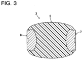
- the post-shaped insulating spacer 3 is composed of a cast product in which a spacer body part 5 made of epoxy resin and a pair of embedded metal fittings 7, 8 being embedded members made of metal are integrally molded.
- the spacer body part 5 having electrical insulation is formed in a barrel shape bulging out at a middle portion of a pillar.
- the pair of embedded metal fittings 7, 8 are provided at end portions of the spacer body part 5 respectively.
- one embedded metal fitting 7 is mechanically coupled to the high-voltage conductor 22 and the other embedded metal fitting 8 is mechanically coupled to an inner portion of the connecting container 20.
- the insulating spacer 3 supports the high-voltage conductor 22 on an inner wall surface of the connecting container 20 from the bottom side of the high-voltage conductor 22 with the axial direction of the insulating spacer 3 standing up.
- an epoxy resin being a thermosetting casting material is employed. More specifically, used as the epoxy resin is a composition made by mixing an acid anhydride-based curing agent and alumina as an inorganic filler into a liquid bisphenol A-based epoxy resin.
- a rugged portion constituting a plurality of steps in the shape of stairs from its middle portion toward each end portion in the axial direction of the insulating spacer 3.
- This rugged portion is formed to roughen the surface of the spacer body part 5 on an order of, for example, several microns.
- the rugged portion functions to inhibit motion of electrons to suppress the electrostatic charge of the spacer body part 5 itself.
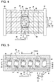
- the casting mold 25 includes a mold body 26 having a fixed mold part 30 and a movable mold part 29 movable in an arrow X1-X2 direction, mold fixing plates 37,38 on which the movable mold part 29 and the fixed mold part 30 are fixed respectively, and inserts 27, 28 installed in the respective movable mold part 29 and fixed mold part 30.
- the casting mold 25 of this embodiment is a mold of the specifications for multi-cavity (six-cavity in this embodiment) casting of insulating spacers 3 as cast products while employing a so-called pressure-gelation method.
- a material injection port 32 in the mold body 26 composed of the movable mold part 29 and the fixed mold part 30 of the casting mold 25, a material injection port 32, a plurality of cavity parts (mold cavities) 31, a runner part 40 and material reservoirs 46 and so on are formed.
- the material injection port 32 is a sprue (a pouring gate) provided at the bottom portion of the mold body 26 for injecting the thermosetting casting material under pressure from the outside of the mold body 26 into the mold body 26.
- the cavity parts 31 are composed of recessed portions (hollow portions) corresponding to the shapes of products respectively.
- the runner part 40 constitutes transfer paths for the casting material leading from the material injection port 32 to the individual cavity parts 31.
- the material reservoirs 46 are formed on the upper side of the cavity parts 31 respectively and house the casting material pushed out from the cavity parts 31 side when the casting material is filled into the cavity parts 31. Further, the material reservoirs 46 house air remaining in the cavity parts 31 (air causing occurrence of voids) pushed out from the inside of the cavity parts 31 together with the casting material. Further, inside the mold body 26, relay paths 45 coupling the material reservoirs 46 and the cavity parts 31 and so on are provided.
- each of the cavity parts 31 is structured in a shape capable of providing, as a cast product, a spacer body part 5 having a size, for example, larger than 7000 cc(cm 3 ) in volume and 170 mm in maximum thickness by thermally curing the casting material filled therein.
- a hydraulic cylinder 39 is coupled to the mold fixing plate 37 fixing the movable mold part 29, for example.
- This cylinder 39 opens and closes the casting mold 25 by moving backward and forward the movable mold part 29 together with the mold fixing plate 37 from and to the fixed mold part 30.
- a material injection nozzle 33 for injecting (filling), via the material injection port 32, the casting material transferred via a material transfer pipe 34 into the cavity parts 31 of the mold body 26.
- a cylinder mechanism including a piston for pressure-supplying liquid epoxy resin being the thermosetting casting material via the material inspection nozzle 33 and the material injection port 32 to the inside of the cavity parts 31 of the mold body 26 and the like are connected to the base portion side of the above-described material transfer pipe 34.
- a heating mechanism 36 including a temperature sensor disposed near the cavity parts 31 and a plurality of bar-shaped heaters 35 capable of controlling temperature is provided in the casting mold 25 of this embodiment.
- the above-described heaters 35 are built-in in a manner that they are arranged in a lattice form in the mold body 26 composed of the movable mold part 29 and the fixed mold part 30.
- This heating mechanism 36 heats (heat-controls) the mold body 26 so that the heating temperature becomes higher from the bottom portion to the upper portion of the mold body 26.
- the heating mechanism 36 heats a portion near the material injection port 32 lower than the cavity parts 31 in the mold body 26 illustrated in Fig. 4, Fig. 5 to, for example, about 110 to 120°C, while heating an upper portion including the formation portion of the cavity parts 31 in the mold body 26 illustrated in Fig. 4, Fig. 5 to, for example, about 130 to 140°C.
- the heating mechanism 36 controls the temperature inside the mold body 26 with a temperature gradient so that the temperature near the material injection port 32 is lower, for example, by about 10 to 20°C than, for example, the upper portion including the formation portion of the cavity parts 31 in the mold body 26. This is to suppress that the casting material near the material injection port 32 is thermally cured earlier than other portions during transition of casting.
- the runner part 40 includes a first-order runner 41 divided into two branches, from an upper end portion of the material injection port 32, each extending in the horizontal direction (an arrow Y1-Y2 direction), and second-order runners 42 each extending in a direction (an arrow Z1 direction) from a middle portion of the first-order runner 41 toward the cavity part 31.
- Dead end (upper end) portions of the second-order runners 42 are structured as gates 43 and open in the cavity parts 31 respectively.
- the individual cavity parts 31 are formed in a manner that positions thereof in the height direction (the arrow Z1 direction) in the mold body 26 are aligned with each other as illustrated in Fig. 5 .
- the cavity parts 31 are arranged to be regularly disposed side by side along the horizontal direction (the arrow Y1-Y2 direction) in the mold body 26. Accordingly, the casting material to be supplied into the first-order runner 41 through the material injection port 32 is filled in the whole first-order runner 41, then moves up in the arrow Z1 direction in the second-order runners 42 against its self-weight, and is filled in the individual cavity parts 31 at substantially the same time.
- This can suppress variations in heating time for the casting material in the individual cavity parts 31, thereby uniformizing various characteristics including electric insulation and mechanical property of the cast products (the insulating spacers 3) obtained by multi-cavity casting which have been respectively thermally cured.
- the runner part 40 and the cavity parts 31 are structured to be laid out substantially symmetrically (on the right side and the left side in Fig. 5 ) about the position of the material injection port 32 in the mold body 26. This makes it possible to make the transfer times of the casting material transferred in the first-order runner 41 and the second-order runners 42 of the runner part 40 (or the heating times after filled in the cavity parts 31) the same on the right side and left side of the material injection port 32, thereby suppressing variations in various characteristics between the (three) cast products cast on the right side in Fig. 5 and the (three) cast products cast on the left side in Fig. 5 .
- the cavity parts 31 are structured so that each of the cast products is cast in an inclined state as illustrated in Fig. 5 .
- This structure is intended to prevent the flow of the casting material from being inhibited by the physical interference of the embedded metal fittings 7, 8 installed inside the cavity parts 31. This makes it easier to push out the air remaining in the cavity parts 31 together with excessive casting material, thus making it possible to suppress occurrence of voids during the filling of the casting material into the cavity parts 31.
- the embedded metal fittings 7, 8 are installed first in the inserts 27, 28 with O-rings or the like interposed therebetween. Then, the inserts 27,28 to which the embedded metal fittings 7, 8 are attached are set (installed) in a mold part on the side which has been determined in advance of the mold body 26, namely, one of the movable mold part 29 and the fixed mold part 30.
- the inside of the mold body 26 in the casting mold 25 is heated.
- the temperature is adjusted through the heating mechanism 36 so that a portion except the portion near (around) the material injection port 32 is heated to 135°C and the portion near the material injection port 32 is heated to 125°C lower by 10°C in the mold body 26 illustrated in Fig. 4 .
- Such temperature adjustment is performed to suppress the thermal cure of a casting material 48 at the material injection port 32.
- thermosetting casting material 48 the liquid epoxy resin
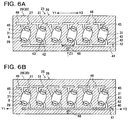
- Fig. 6A injection rate of 50 cc(cm 3 )/sec from the material injection nozzle 33.
- the casting material 48 is divided from the upper end portion of the material injection port 32 into two branches along the first-order runner 41 extending in the horizontal direction (the arrow Y1-Y2 direction).
- the casting material 48 is then filled in the whole first-order runner 41 as illustrated in Fig. 6B .
- the casting material 48 then moves up in the arrow Z1 direction against its self-weight in the second-order runners 42 extending in the vertical direction as illustrated in Fig. 6C .
- the casting material 48 is filled in the individual cavity parts 31 at substantially the same time via the gates 43 as illustrated in Fig. 6D .
- the cylinder mechanism including the piston provided at the base end side of the material transfer pipe 34 and the like are controlled, whereby the casting material 48 is pressure-supplied into the cavity parts 31 of the heated mold body 26 in a manner to compensate for a compressed volume during the cure of the resin by cross linking reaction.
- pressure-supply (refilling under pressure) of the casting material 48 outer peripheral portions of the casting material 48 in the cavity parts 31 of the mold body 26 are thermally cured into semi-cured matters as illustrated in Fig. 6D .
- reaction heat during the cross-linking reaction generated when the thermal cure of the semi-cured matters obtained in the mold body 26 proceeds toward central portions thereof causes the semi-cured matters internally to generate heat from the central portions thereof.
- the pressure-supply of the casting material 48 is stopped, the semi-cured matters are then taken out (released) of the cavity parts 31 of the mold body 26, and the inserts 27,28 are removed from the semi-cured matters. Subsequently, the semi-cured matters taken out of the mold body 26 are left stand, for example, for about 30 minutes, whereby the internal heat generation of the semi-cured matters is continued to thermally cure the whole semi-cured matters including the central portions.
- the post-shaped insulating spacers (cast products) 3 having a final physical property as solid insulators such as high heat resistance property or the like are obtained as illustrated in Fig. 3 .
- the individual cavity parts 31 are formed in a manner that the positions thereof in the height direction (the arrow Z1 direction) in the mold body 26 are aligned with each other as illustrated in Fig. 5 , Fig. 6B to Fig. 6D . Therefore, it becomes possible to fill the casting material to the cavity parts 31 at substantially the same time. Therefore, the casting mold 25 makes it possible to make the heating periods of the casting material in the cavity parts 31 substantially the same. As a result, various characteristics including the mechanical strength, the heat resistance, the electric insulation of the thermally cured cast products (the insulating spacers 3) obtained by multi-cavity casting can be made uniform. This ensures that the insulating spacers 3 can be manufactured with a stable quality and the productivity can be improved.
- the cavity parts 31 are arranged in a manner that the positions thereof in the height direction in the mold body 26 are aligned with each other as described above. Therefore, it becomes possible to stabilize various characteristics of the cast products by a comparatively easy temperature control such as control of the heating temperature only in the vertical direction of the mold body 26. Further, by applying the post-shaped insulating spacer 3 which is stabilized in quality as a solid insulator to the supporting portion of the high-voltage conductor 22 as illustrated in Fig. 1, Fig. 2 , the reliability of the insulation of the gas insulated switchgear 1 can be increased.
- FIG. 7 A second embodiment (not in accordance with the invention) will be described based on Fig. 7 . Note that components in Fig. 7 which are the same as those in Fig. 5 described in the first embodiment are given the same numbers and description thereof will be omitted.
- a casting mold 58 of this embodiment is a mold capable of eight-cavity casting of cast products, and includes a runner part 50 in place of the runner part 40 provided in the casting mold 25 for six-cavity casting of cast products in the first embodiment.
- This runner part 50 is formed to constitute transfer paths for the casting material leading from a material injection port 32 to individual cavity parts 31 and in a manner that the lengths of the transfer paths are equal.
- the runner part 50 includes first-order to six-order runners 51 to 56.
- the first-order runner 51 is divided into two branches, from an upper end portion of the material injection port 32, each extending in the horizontal direction (an arrow Y1-Y2 direction).
- the second-order runners 52 each extends in a direction of an upper side of the casting mold 58 (an arrow Z1 direction) from each of end portions of the first-order runner 51.
- the third-order runner 53 is divided into two branches, from an upper end portion of each of the two second-order runners 52, each extending in the horizontal direction.
- the fourth-order runner 54 extends in the direction of the upper side of the casting mold 58 from each of end portions of the third-order runners 53.
- the fifth-order runner 55 is divided into two branches, from an upper end portion of each of the four fourth-order runners 54, each extending in the horizontal direction.
- the six-order runner 56 has the same structure as that of the second-order runner 42 in the first embodiment
- the runner part 50 and the cavity parts 31 are laid out in a substantially symmetrically (on the right side and the left side in Fig. 7 ) about the position of the material injection port 32 in the mold body 26.
- the path lengths of the transfer paths for the casting material leading from the material injection port 32 to the individual cavity parts 31 are equal to each other.
- the casting mold 58 of this embodiment makes it possible to uniformize the heating periods of the casting material in the cavity parts 31 as in the first embodiment and also equalize the transfer times (heating times) of the casting material reaching the cavity parts 31 from the material injection port 32.
- the casting mold 58 can suppress variations in various characteristics among the thermally cured cast products obtained by multi-cavity casting.
- a third embodiment (not in accordance with the invention) will be described based on Fig. 8 to Fig. 10 .
- components in Fig. 8 to Fig. 10 which are the same as those in Fig. 5 , Fig. 7 described in the first and second embodiments are given the same numbers and description thereof will be omitted.
- a casting mold 60 of this embodiment further includes an air exhaust mechanism 61 in addition to the structure of the casting mold 25 according to the first embodiment
- the air exhaust mechanism 61 has a plurality of air exhaust holes 62 leading from individual cavity parts 31 to the outside of a mold body 26 and a plurality of stop valves 63 as valve members closing the plurality of air exhaust holes 62 respectively accompanying filling of the casting material into the cavity parts 31.
- the air exhaust holes 62 are structured as stepped holes opening from individual material reservoirs 46 into the outside of the mold body 26 and have inclined surfaces 64 at middle portions thereof.
- the air exhaust hole 62 is composed of, as illustrated in Fig. 9A and Fig. 9B , a large-diameter hole part 65 on the material reservoir 46 side (a bottom portion side) and a small-diameter hole part 66 on an upper portion side opening to the outside of the mold body 26.
- the stop valve 63 includes a shaft part 67 extending in the vertical direction (an arrow Z1-Z2 direction) and a conical part 68 provided at the lower end of the shaft part 67.
- the shaft part 67 of the stop valve 63 is formed having a diameter smaller than the small-diameter hole part 66 of the air exhaust hole 62 and inserted in the small-diameter hole part 66. In other words, between the small-diameter hole part 66 and the shaft part 67, a predetermined space (clearance) is formed.
- the conical part 68 of the stop valve 63 is disposed in the large-diameter hole part 65 of the air exhaust hole 62.
- the air exhaust mechanism 61 in such a structure is brought into a state that the material reservoir 46 and the cavity part 31 are closed with respect to the outside of the mold body 26 as illustrated in Fig. 9B in a closed state of the stop valve 63 in which the conical part 68 of the stop valve 63 is in contact with the inclined surface 64 of the air exhaust hole 62.
- the air exhaust mechanism 61 is brought into a state that the material reservoir 46 and the cavity part 31 are opened with respect to the outside of the mold body 26 as illustrated in Fig. 9A in an open state of the stop valve 63 in which the conical part 68 of the stop valve 63 is separated from the inclined surface 64 of the air exhaust hole 62.
- the stop vale 63 is pushed down in the arrow Z2 direction by its self-weight into its open state as illustrated in Fig. 9A . This makes it possible to easily release the air remaining in the cavity part 31 and the material reservoir 46 to the outside of the mold body 26 via the air exhaust hole 62.
- the stop valve 63 is pushed up in the arrow Z1 direction by the pressure force in the filling of the casting material 48 into its closed state as illustrated in Fig. 9B .
- the air exhaust hole 62 is closed, thus preventing leakage and the like of the casting material 48.
- evacuation of the air in the cavity parts 31 can be effectively performed while suppressing leakage in filling of the casting material 48 in the casting molds 60, 69 of this embodiment.
- This makes it possible to suppress occurrence of voids causing a decrease in electric insulating performance of the insulating spacers 3 (cast products) and also increase the filling performance of the casting material 48 into the cavity parts 31. Therefore, cast products stable in various characteristics can be obtained.
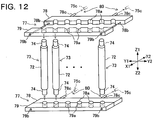
- a casting mold 70 of this embodiment can cast pole-shaped insulating spacers 73 which are entirely formed of only a casting material without embedded metal fittings as illustrated in Fig. 11 and Fig. 12 in place of the post-shaped insulating spacers 73 integrally cast together with the embedded metal fittings 7, 8 by the casting mold 25 in the first embodiment.
- the insulating spacer 73 has a stepped shaft shape and includes a spacer body part 72 and small-diameter parts 74 having a diameter smaller than that of the spacer body part 72 and formed at both end portions of the spacer body part 72.
- This pole-shaped insulating spacer 73 is also disposed as a solid insulator inside the gas insulated switchgear 1 illustrated in Fig. 1 .
- the casting mold 70 of this embodiment includes a mold body 75 and four inserts 77, in place of the mold body 26 and the inserts 27,28 included in the casting mold 25 described in the first embodiment, and an insert fixing mechanism 80.
- the mold body 75 has a fixed mold part 75b and a movable mold part 75a movable in an arrow X1-X2 direction. Further, in the mold body 75, a plurality of mold cavities 71 are formed in a manner that the positions thereof in the height direction in the mold body 75 are aligned with each other.
- the individual inserts 77 integrally and detachably hold a plurality of spacers 73 (cast products) cast in the mold cavities 71 respectively.
- the inserts 77 are structured in a so-called two-piece structure including a movable insert part 78 detachably installed in the movable mold part 75a and a fixed insert part 79 inserted in the fixed mold part 75b with a space between them.
- the movable insert part 78 and the fixed insert part 79 include a plurality of respective recessed portions 78a, 79a recessed in a semicylindrical shape.
- the individual small-diameter parts 74 at both ends of a plurality of insulating spacers 73 respectively cast in the mold cavities 71 are held to be sandwiched between the recessed portions 78a, 79a.
- the inserts 77 in which the fixed insert parts 79 and the movable insert parts 78 are integrally fastened are constructed.
- the casting mold 70 is provided with the insert fixing mechanism 80 detachably fixing the inserts 77 to one of the fixed mold part 75b and the movable mold part 75a.
- the insert fixing mechanism 80 detachably fixing the inserts 77 to one of the fixed mold part 75b and the movable mold part 75a.
- a plurality of press-fit pins 78c are projectingly provided at the movable insert part 78, and the press-fit pins 78c are press-fitted (detachably fixed) via O-rings to pin press-fit holes 75c drilled in advance in the movable mold art 75a.
- recessed portions slightly larger in size than the outer shape of the fixed insert parts 79 are formed in the fixed mold part 75b, and the fixed insert parts 79 are inserted into the recessed portions in a non-press-fit state.
- the inserts 77 made by integrally fastening the fixed insert parts 79 and the movable insert parts 78 are set (detachably fixed) in the movable mold part 75a to close the mold body 75 before casting of the insulating spacers 73 is started.
- the movable insert parts 78 are moved backward in an arrow X2 direction to open the mold body 75.
- the small-diameter parts 74 of the insulating spacers 73 are held to be sandwiched between the recessed portions 78a, 79a and the movable insert parts 78 of the inserts 77 are fixed to the movable mold part 75a, so that the mold body 75 is opened with all of the cast products (the insulating spacers 73) fixed to the movable mold part 75a.
- the insulating spacers 73 being cast products can be fixed to one of the fixed mold part 75b and the movable mold part 75a (the movable mold part 75a side in this embodiment).
- the individual cast insulating spacers 73 can be efficiently taken out via the inserts 77 in the two-piece structure. More specifically, with the casting mold 70, the insulating spacers 73 which are entirely formed of only the casting material without embedded metal fittings can be easily released from the mold, for example, without flaw.
- a casting mold 81 in which the air exhaust mechanism 61 of the third embodiment is added to the casting mold 70 of this embodiment may be structured.
- thermosetting casting material for example, in the above embodiments.
- a silicone resin made by combining a predetermined curing agent and a filler is also applicable.
Landscapes
- Engineering & Computer Science (AREA)
- Manufacturing & Machinery (AREA)
- Mechanical Engineering (AREA)
- Casting Or Compression Moulding Of Plastics Or The Like (AREA)
- Moulds For Moulding Plastics Or The Like (AREA)
Claims (2)
- Gussform (70), die Folgendes umfasst:einen Formkörper (75), der an einem unteren Abschnitt davon eine Materialeinspritzöffnung (32) zum Einspritzen eines warmhärtenden Gussmaterials (48) unter Druck umfasst; undmehrere Formhohlräume (71), die entlang der horizontalen Richtung in dem Formkörper (75) angeordnet sind und jeweils mit dem von der Materialeinspritzöffnung (32) am unteren Abschnitt des Formkörpers (75) eingespritzten Gussmaterial (48) zu füllen sind;wobei der Formkörper (75) einen festen Formteil (75b) und einen beweglichen Formteil (75a) aufweist, undwobei die Gussform (70) durch Folgendes gekennzeichnet ist:einen Einsatz (77), der lösbar im Formkörper (75) befestigt ist, wobei der Einsatz (77) ausgestaltet ist, um mehrere geformte Produkte (73), die jeweils in den einzelnen Formhohlräumen (71) zu formen sind, lösbar zu halten; undeinen Einsatzbefestigungsmechanismus (80), der ausgestaltet ist, um den Einsatz (77) lösbar an einem von dem festen Formteil (75b) und dem beweglichen Formteil (75a) zu befestigen.
- Gussform (25) nach Anspruch 1, die ferner einen Heizmechanismus (36) umfasst, der ausgestaltet ist, um den Formkörper (26) derart zu erhitzen, dass eine Heiztemperatur von dem unteren Abschnitt in Richtung des oberen Abschnitts des Formkörpers (26) höher wird.
Applications Claiming Priority (2)
| Application Number | Priority Date | Filing Date | Title |
|---|---|---|---|
| JP2010173140A JP2012030536A (ja) | 2010-07-30 | 2010-07-30 | 注形用金型及びガス絶縁開閉装置 |
| EP20110175768 EP2412504A3 (de) | 2010-07-30 | 2011-07-28 | Gussform und gasisoliertes Schaltgetriebe |
Related Parent Applications (4)
| Application Number | Title | Priority Date | Filing Date |
|---|---|---|---|
| EP11175768 Previously-Filed-Application | 2011-07-28 | ||
| EP20110175768 Division EP2412504A3 (de) | 2010-07-30 | 2011-07-28 | Gussform und gasisoliertes Schaltgetriebe |
| EP20110175768 Previously-Filed-Application EP2412504A3 (de) | 2010-07-30 | 2011-07-28 | Gussform und gasisoliertes Schaltgetriebe |
| EP11175768.8 Division | 2011-07-28 |
Publications (2)
| Publication Number | Publication Date |
|---|---|
| EP2540468A1 EP2540468A1 (de) | 2013-01-02 |
| EP2540468B1 true EP2540468B1 (de) | 2016-04-20 |
Family
ID=44512691
Family Applications (2)
| Application Number | Title | Priority Date | Filing Date |
|---|---|---|---|
| EP20110175768 Withdrawn EP2412504A3 (de) | 2010-07-30 | 2011-07-28 | Gussform und gasisoliertes Schaltgetriebe |
| EP12186218.9A Not-in-force EP2540468B1 (de) | 2010-07-30 | 2011-07-28 | Gussform |
Family Applications Before (1)
| Application Number | Title | Priority Date | Filing Date |
|---|---|---|---|
| EP20110175768 Withdrawn EP2412504A3 (de) | 2010-07-30 | 2011-07-28 | Gussform und gasisoliertes Schaltgetriebe |
Country Status (3)
| Country | Link |
|---|---|
| EP (2) | EP2412504A3 (de) |
| JP (1) | JP2012030536A (de) |
| CN (1) | CN102343650B (de) |
Families Citing this family (4)
| Publication number | Priority date | Publication date | Assignee | Title |
|---|---|---|---|---|
| EP3208065B1 (de) * | 2016-02-19 | 2021-09-15 | General Electric Technology GmbH | Form und verfahren zum flexiblen halten von einlegeteilen im werkzeug während des spritzgiessens |
| CN107068307A (zh) * | 2017-04-14 | 2017-08-18 | 保定冀开电力器材有限公司 | 一种工期短效率高的复合绝缘子生产方法 |
| CN109605677B (zh) * | 2018-11-13 | 2021-06-08 | 广州市鸿益塑料有限公司 | 一种共混合成塑料制品加工装置 |
| CN116001209A (zh) * | 2022-12-29 | 2023-04-25 | 歌尔光学科技有限公司 | 一种注胶模具及注胶系统 |
Family Cites Families (21)
| Publication number | Priority date | Publication date | Assignee | Title |
|---|---|---|---|---|
| US2672653A (en) * | 1952-03-26 | 1954-03-23 | Essex Wire Corp | Injection mold |
| US4370511A (en) * | 1981-03-17 | 1983-01-25 | Westinghouse Electric Corp. | Flexible gas insulated transmission line having regions of reduced electric field |
| JPS57203532A (en) * | 1981-06-10 | 1982-12-13 | Toshiba Chem Corp | Mold for molding thermosetting resin |
| DE3338783C1 (de) * | 1983-10-26 | 1985-03-21 | Werner & Pfleiderer, 7000 Stuttgart | Spritzgießform zur Herstellung von Formartikeln aus wärmehärtbaren Werkstoffen |
| JPS60127112A (ja) * | 1983-12-14 | 1985-07-06 | Matsushita Electric Works Ltd | 成形金型のエア抜き装置 |
| DE3345133A1 (de) * | 1983-12-14 | 1985-09-26 | Bopp & Reuther Gmbh, 6800 Mannheim | Absperrkeil fuer absperrschieber |
| US4662307A (en) * | 1985-05-31 | 1987-05-05 | Corning Glass Works | Method and apparatus for recoating optical waveguide fibers |
| US5013513A (en) * | 1989-05-26 | 1991-05-07 | Husky Injection Molding Systems Ltd. | Method of removing gas from the cavity and stabilizing the core during injection molding |
| JPH03225930A (ja) * | 1990-01-31 | 1991-10-04 | Nec Corp | 半導体装置の樹脂封止装置 |
| JPH0564820A (ja) * | 1991-09-06 | 1993-03-19 | Toshiba Corp | 注型金型 |
| TW208759B (de) * | 1991-10-24 | 1993-07-01 | American Telephone & Telegraph | |
| US6002085A (en) * | 1991-11-18 | 1999-12-14 | Hitachi, Ltd. | Gas insulated switchgear |
| IT239392Y1 (it) * | 1995-04-07 | 2001-02-26 | Valex Spa | Fodero di protezione in materiale plastico, particolarmente per lamedi tagliasiepi |
| JPH09180561A (ja) * | 1995-12-26 | 1997-07-11 | Hitachi Ltd | ガス絶縁機器 |
| JP3792420B2 (ja) * | 1998-12-09 | 2006-07-05 | 株式会社小糸製作所 | 車輌用灯具の樹脂製品成形用の金型装置 |
| JP4794033B2 (ja) * | 2000-10-13 | 2011-10-12 | 住友電気工業株式会社 | 成形用型及び光ファイバ接続部の補強方法並びに光ファイバケーブル |
| JP4046319B2 (ja) * | 2002-04-11 | 2008-02-13 | 株式会社東芝 | 注型装置 |
| JP4284303B2 (ja) * | 2005-06-02 | 2009-06-24 | 株式会社東芝 | 注型装置 |
| JP4768401B2 (ja) * | 2005-11-02 | 2011-09-07 | 株式会社東芝 | 樹脂注型金型 |
| US7651644B2 (en) * | 2006-05-31 | 2010-01-26 | Graham Packaging Company, Lp | Controlling delivery of polymer material in a sequential injection molding process |
| JP2008047573A (ja) * | 2006-08-11 | 2008-02-28 | Matsushita Electric Ind Co Ltd | 樹脂封止型半導体装置の製造装置、樹脂封止型半導体装置の製造方法、および樹脂封止型半導体装置 |
-
2010
- 2010-07-30 JP JP2010173140A patent/JP2012030536A/ja active Pending
-
2011
- 2011-07-27 CN CN201110219235.6A patent/CN102343650B/zh active Active
- 2011-07-28 EP EP20110175768 patent/EP2412504A3/de not_active Withdrawn
- 2011-07-28 EP EP12186218.9A patent/EP2540468B1/de not_active Not-in-force
Also Published As
| Publication number | Publication date |
|---|---|
| EP2540468A1 (de) | 2013-01-02 |
| CN102343650A (zh) | 2012-02-08 |
| EP2412504A3 (de) | 2012-03-28 |
| JP2012030536A (ja) | 2012-02-16 |
| EP2412504A2 (de) | 2012-02-01 |
| CN102343650B (zh) | 2014-09-03 |
Similar Documents
| Publication | Publication Date | Title |
|---|---|---|
| KR101034342B1 (ko) | 저전압, 중간 전압 및 고전압 스위칭 설비를 위한 회로 차단부를 제조하기 위한 방법 및 그에 상응하는 회로 차단부 | |
| US6897396B2 (en) | Switch gear and method of manufacturing thereof | |
| EP2540468B1 (de) | Gussform | |
| US8785802B2 (en) | Circuit-breaker pole part and method for producing such a pole part | |
| US8677609B2 (en) | Method for producing a circuit-breaker pole part | |
| CN101796603B (zh) | 用于制造中压开关装置的电极部件的方法和电极部件本身 | |
| CN102163510A (zh) | 一种固封极柱的生产工艺 | |
| CN102044354A (zh) | 用于制造断路器极柱部分的方法 | |
| KR100860528B1 (ko) | 고전압 부하개폐기 및 그 제조방법 | |
| US20060011589A1 (en) | Production of a circuit-breaker pole, insulated by a solid material | |
| CN102687226A (zh) | 具有多腔室壳体的电气设备 | |
| CN107932811B (zh) | 一种干式套管绝缘体真空加气浇注系统及其浇注方法 | |
| EP2278603B1 (de) | Verfahren zur Herstellung einer Stromanschlussklemme für einen eingebetteten Schalterpolteil | |
| CN109791858A (zh) | 高压开关装置和带有高压开关装置的开关设备以及高压开关装置的制造方法 | |
| JP3699865B2 (ja) | 注型装置、離型装置、及び保護治具 | |
| CN105655192A (zh) | 一种采用绝缘护套包覆真空灭弧室的固封极柱的制造方法 | |
| JP5646247B2 (ja) | 注形品の製造方法及び金型 | |
| KR100444737B1 (ko) | 입력단자가 다접점 접촉자로 된 계기용 변압기 및 그 성형방법 | |
| CN220331802U (zh) | 注射模具、绝缘子间隔件和用于开关设备的绝缘子 | |
| CN102983027A (zh) | 一种有衬套的注塑型极柱制造技术 | |
| CN213124260U (zh) | 一种全封闭式多瓷柱单体的隔离开关 | |
| KR101123251B1 (ko) | 에폭시몰드 절연 부하개폐기 | |
| CN119348022B (zh) | 一种极柱模具 | |
| JP2023511494A (ja) | 透過性壁カプセル化金型 | |
| CN119189196B (zh) | 一种电磁浮模内注射成型工艺及结构 |
Legal Events
| Date | Code | Title | Description |
|---|---|---|---|
| PUAI | Public reference made under article 153(3) epc to a published international application that has entered the european phase |
Free format text: ORIGINAL CODE: 0009012 |
|
| AC | Divisional application: reference to earlier application |
Ref document number: 2412504 Country of ref document: EP Kind code of ref document: P |
|
| AK | Designated contracting states |
Kind code of ref document: A1 Designated state(s): AL AT BE BG CH CY CZ DE DK EE ES FI FR GB GR HR HU IE IS IT LI LT LU LV MC MK MT NL NO PL PT RO RS SE SI SK SM TR |
|
| AX | Request for extension of the european patent |
Extension state: BA ME |
|
| 17P | Request for examination filed |
Effective date: 20130701 |
|
| RBV | Designated contracting states (corrected) |
Designated state(s): AL AT BE BG CH CY CZ DE DK EE ES FI FR GB GR HR HU IE IS IT LI LT LU LV MC MK MT NL NO PL PT RO RS SE SI SK SM TR |
|
| 17Q | First examination report despatched |
Effective date: 20140519 |
|
| GRAP | Despatch of communication of intention to grant a patent |
Free format text: ORIGINAL CODE: EPIDOSNIGR1 |
|
| INTG | Intention to grant announced |
Effective date: 20151201 |
|
| GRAS | Grant fee paid |
Free format text: ORIGINAL CODE: EPIDOSNIGR3 |
|
| GRAA | (expected) grant |
Free format text: ORIGINAL CODE: 0009210 |
|
| AC | Divisional application: reference to earlier application |
Ref document number: 2412504 Country of ref document: EP Kind code of ref document: P |
|
| AK | Designated contracting states |
Kind code of ref document: B1 Designated state(s): AL AT BE BG CH CY CZ DE DK EE ES FI FR GB GR HR HU IE IS IT LI LT LU LV MC MK MT NL NO PL PT RO RS SE SI SK SM TR |
|
| REG | Reference to a national code |
Ref country code: GB Ref legal event code: FG4D |
|
| REG | Reference to a national code |
Ref country code: CH Ref legal event code: EP |
|
| REG | Reference to a national code |
Ref country code: AT Ref legal event code: REF Ref document number: 791900 Country of ref document: AT Kind code of ref document: T Effective date: 20160515 |
|
| REG | Reference to a national code |
Ref country code: IE Ref legal event code: FG4D |
|
| REG | Reference to a national code |
Ref country code: DE Ref legal event code: R096 Ref document number: 602011025823 Country of ref document: DE |
|
| REG | Reference to a national code |
Ref country code: FR Ref legal event code: PLFP Year of fee payment: 6 |
|
| REG | Reference to a national code |
Ref country code: CH Ref legal event code: NV Representative=s name: FIAMMENGHI-FIAMMENGHI, CH |
|
| REG | Reference to a national code |
Ref country code: LT Ref legal event code: MG4D |
|
| REG | Reference to a national code |
Ref country code: AT Ref legal event code: MK05 Ref document number: 791900 Country of ref document: AT Kind code of ref document: T Effective date: 20160420 |
|
| REG | Reference to a national code |
Ref country code: NL Ref legal event code: MP Effective date: 20160420 |
|
| PG25 | Lapsed in a contracting state [announced via postgrant information from national office to epo] |
Ref country code: FI Free format text: LAPSE BECAUSE OF FAILURE TO SUBMIT A TRANSLATION OF THE DESCRIPTION OR TO PAY THE FEE WITHIN THE PRESCRIBED TIME-LIMIT Effective date: 20160420 Ref country code: NL Free format text: LAPSE BECAUSE OF FAILURE TO SUBMIT A TRANSLATION OF THE DESCRIPTION OR TO PAY THE FEE WITHIN THE PRESCRIBED TIME-LIMIT Effective date: 20160420 Ref country code: NO Free format text: LAPSE BECAUSE OF FAILURE TO SUBMIT A TRANSLATION OF THE DESCRIPTION OR TO PAY THE FEE WITHIN THE PRESCRIBED TIME-LIMIT Effective date: 20160720 Ref country code: LT Free format text: LAPSE BECAUSE OF FAILURE TO SUBMIT A TRANSLATION OF THE DESCRIPTION OR TO PAY THE FEE WITHIN THE PRESCRIBED TIME-LIMIT Effective date: 20160420 Ref country code: PL Free format text: LAPSE BECAUSE OF FAILURE TO SUBMIT A TRANSLATION OF THE DESCRIPTION OR TO PAY THE FEE WITHIN THE PRESCRIBED TIME-LIMIT Effective date: 20160420 |
|
| PG25 | Lapsed in a contracting state [announced via postgrant information from national office to epo] |
Ref country code: LV Free format text: LAPSE BECAUSE OF FAILURE TO SUBMIT A TRANSLATION OF THE DESCRIPTION OR TO PAY THE FEE WITHIN THE PRESCRIBED TIME-LIMIT Effective date: 20160420 Ref country code: SE Free format text: LAPSE BECAUSE OF FAILURE TO SUBMIT A TRANSLATION OF THE DESCRIPTION OR TO PAY THE FEE WITHIN THE PRESCRIBED TIME-LIMIT Effective date: 20160420 Ref country code: RS Free format text: LAPSE BECAUSE OF FAILURE TO SUBMIT A TRANSLATION OF THE DESCRIPTION OR TO PAY THE FEE WITHIN THE PRESCRIBED TIME-LIMIT Effective date: 20160420 Ref country code: ES Free format text: LAPSE BECAUSE OF FAILURE TO SUBMIT A TRANSLATION OF THE DESCRIPTION OR TO PAY THE FEE WITHIN THE PRESCRIBED TIME-LIMIT Effective date: 20160420 Ref country code: AT Free format text: LAPSE BECAUSE OF FAILURE TO SUBMIT A TRANSLATION OF THE DESCRIPTION OR TO PAY THE FEE WITHIN THE PRESCRIBED TIME-LIMIT Effective date: 20160420 Ref country code: GR Free format text: LAPSE BECAUSE OF FAILURE TO SUBMIT A TRANSLATION OF THE DESCRIPTION OR TO PAY THE FEE WITHIN THE PRESCRIBED TIME-LIMIT Effective date: 20160721 Ref country code: PT Free format text: LAPSE BECAUSE OF FAILURE TO SUBMIT A TRANSLATION OF THE DESCRIPTION OR TO PAY THE FEE WITHIN THE PRESCRIBED TIME-LIMIT Effective date: 20160822 Ref country code: HR Free format text: LAPSE BECAUSE OF FAILURE TO SUBMIT A TRANSLATION OF THE DESCRIPTION OR TO PAY THE FEE WITHIN THE PRESCRIBED TIME-LIMIT Effective date: 20160420 |
|
| PG25 | Lapsed in a contracting state [announced via postgrant information from national office to epo] |
Ref country code: BE Free format text: LAPSE BECAUSE OF FAILURE TO SUBMIT A TRANSLATION OF THE DESCRIPTION OR TO PAY THE FEE WITHIN THE PRESCRIBED TIME-LIMIT Effective date: 20160420 Ref country code: IT Free format text: LAPSE BECAUSE OF FAILURE TO SUBMIT A TRANSLATION OF THE DESCRIPTION OR TO PAY THE FEE WITHIN THE PRESCRIBED TIME-LIMIT Effective date: 20160420 |
|
| REG | Reference to a national code |
Ref country code: DE Ref legal event code: R097 Ref document number: 602011025823 Country of ref document: DE |
|
| PG25 | Lapsed in a contracting state [announced via postgrant information from national office to epo] |
Ref country code: SK Free format text: LAPSE BECAUSE OF FAILURE TO SUBMIT A TRANSLATION OF THE DESCRIPTION OR TO PAY THE FEE WITHIN THE PRESCRIBED TIME-LIMIT Effective date: 20160420 Ref country code: CZ Free format text: LAPSE BECAUSE OF FAILURE TO SUBMIT A TRANSLATION OF THE DESCRIPTION OR TO PAY THE FEE WITHIN THE PRESCRIBED TIME-LIMIT Effective date: 20160420 Ref country code: EE Free format text: LAPSE BECAUSE OF FAILURE TO SUBMIT A TRANSLATION OF THE DESCRIPTION OR TO PAY THE FEE WITHIN THE PRESCRIBED TIME-LIMIT Effective date: 20160420 Ref country code: RO Free format text: LAPSE BECAUSE OF FAILURE TO SUBMIT A TRANSLATION OF THE DESCRIPTION OR TO PAY THE FEE WITHIN THE PRESCRIBED TIME-LIMIT Effective date: 20160420 Ref country code: DK Free format text: LAPSE BECAUSE OF FAILURE TO SUBMIT A TRANSLATION OF THE DESCRIPTION OR TO PAY THE FEE WITHIN THE PRESCRIBED TIME-LIMIT Effective date: 20160420 |
|
| PLBE | No opposition filed within time limit |
Free format text: ORIGINAL CODE: 0009261 |
|
| STAA | Information on the status of an ep patent application or granted ep patent |
Free format text: STATUS: NO OPPOSITION FILED WITHIN TIME LIMIT |
|
| PG25 | Lapsed in a contracting state [announced via postgrant information from national office to epo] |
Ref country code: SM Free format text: LAPSE BECAUSE OF FAILURE TO SUBMIT A TRANSLATION OF THE DESCRIPTION OR TO PAY THE FEE WITHIN THE PRESCRIBED TIME-LIMIT Effective date: 20160420 |
|
| GBPC | Gb: european patent ceased through non-payment of renewal fee |
Effective date: 20160728 |
|
| 26N | No opposition filed |
Effective date: 20170123 |
|
| PG25 | Lapsed in a contracting state [announced via postgrant information from national office to epo] |
Ref country code: MC Free format text: LAPSE BECAUSE OF FAILURE TO SUBMIT A TRANSLATION OF THE DESCRIPTION OR TO PAY THE FEE WITHIN THE PRESCRIBED TIME-LIMIT Effective date: 20160420 |
|
| REG | Reference to a national code |
Ref country code: IE Ref legal event code: MM4A |
|
| PG25 | Lapsed in a contracting state [announced via postgrant information from national office to epo] |
Ref country code: SI Free format text: LAPSE BECAUSE OF FAILURE TO SUBMIT A TRANSLATION OF THE DESCRIPTION OR TO PAY THE FEE WITHIN THE PRESCRIBED TIME-LIMIT Effective date: 20160420 Ref country code: GB Free format text: LAPSE BECAUSE OF NON-PAYMENT OF DUE FEES Effective date: 20160728 |
|
| REG | Reference to a national code |
Ref country code: FR Ref legal event code: PLFP Year of fee payment: 7 |
|
| PG25 | Lapsed in a contracting state [announced via postgrant information from national office to epo] |
Ref country code: IE Free format text: LAPSE BECAUSE OF NON-PAYMENT OF DUE FEES Effective date: 20160728 |
|
| PG25 | Lapsed in a contracting state [announced via postgrant information from national office to epo] |
Ref country code: LU Free format text: LAPSE BECAUSE OF NON-PAYMENT OF DUE FEES Effective date: 20160728 |
|
| PG25 | Lapsed in a contracting state [announced via postgrant information from national office to epo] |
Ref country code: CY Free format text: LAPSE BECAUSE OF FAILURE TO SUBMIT A TRANSLATION OF THE DESCRIPTION OR TO PAY THE FEE WITHIN THE PRESCRIBED TIME-LIMIT Effective date: 20160420 Ref country code: HU Free format text: LAPSE BECAUSE OF FAILURE TO SUBMIT A TRANSLATION OF THE DESCRIPTION OR TO PAY THE FEE WITHIN THE PRESCRIBED TIME-LIMIT; INVALID AB INITIO Effective date: 20110728 |
|
| REG | Reference to a national code |
Ref country code: FR Ref legal event code: PLFP Year of fee payment: 8 |
|
| PG25 | Lapsed in a contracting state [announced via postgrant information from national office to epo] |
Ref country code: TR Free format text: LAPSE BECAUSE OF FAILURE TO SUBMIT A TRANSLATION OF THE DESCRIPTION OR TO PAY THE FEE WITHIN THE PRESCRIBED TIME-LIMIT Effective date: 20160420 Ref country code: IS Free format text: LAPSE BECAUSE OF FAILURE TO SUBMIT A TRANSLATION OF THE DESCRIPTION OR TO PAY THE FEE WITHIN THE PRESCRIBED TIME-LIMIT Effective date: 20160420 Ref country code: MK Free format text: LAPSE BECAUSE OF FAILURE TO SUBMIT A TRANSLATION OF THE DESCRIPTION OR TO PAY THE FEE WITHIN THE PRESCRIBED TIME-LIMIT Effective date: 20160420 Ref country code: MT Free format text: LAPSE BECAUSE OF NON-PAYMENT OF DUE FEES Effective date: 20160731 |
|
| PG25 | Lapsed in a contracting state [announced via postgrant information from national office to epo] |
Ref country code: BG Free format text: LAPSE BECAUSE OF FAILURE TO SUBMIT A TRANSLATION OF THE DESCRIPTION OR TO PAY THE FEE WITHIN THE PRESCRIBED TIME-LIMIT Effective date: 20160420 |
|
| PGFP | Annual fee paid to national office [announced via postgrant information from national office to epo] |
Ref country code: FR Payment date: 20180612 Year of fee payment: 8 |
|
| PG25 | Lapsed in a contracting state [announced via postgrant information from national office to epo] |
Ref country code: AL Free format text: LAPSE BECAUSE OF FAILURE TO SUBMIT A TRANSLATION OF THE DESCRIPTION OR TO PAY THE FEE WITHIN THE PRESCRIBED TIME-LIMIT Effective date: 20160420 |
|
| PGFP | Annual fee paid to national office [announced via postgrant information from national office to epo] |
Ref country code: DE Payment date: 20180717 Year of fee payment: 8 |
|
| PGFP | Annual fee paid to national office [announced via postgrant information from national office to epo] |
Ref country code: CH Payment date: 20180713 Year of fee payment: 8 |
|
| REG | Reference to a national code |
Ref country code: DE Ref legal event code: R119 Ref document number: 602011025823 Country of ref document: DE |
|
| REG | Reference to a national code |
Ref country code: CH Ref legal event code: PL |
|
| PG25 | Lapsed in a contracting state [announced via postgrant information from national office to epo] |
Ref country code: DE Free format text: LAPSE BECAUSE OF NON-PAYMENT OF DUE FEES Effective date: 20200201 |
|
| PG25 | Lapsed in a contracting state [announced via postgrant information from national office to epo] |
Ref country code: LI Free format text: LAPSE BECAUSE OF NON-PAYMENT OF DUE FEES Effective date: 20190731 Ref country code: CH Free format text: LAPSE BECAUSE OF NON-PAYMENT OF DUE FEES Effective date: 20190731 |
|
| PG25 | Lapsed in a contracting state [announced via postgrant information from national office to epo] |
Ref country code: FR Free format text: LAPSE BECAUSE OF NON-PAYMENT OF DUE FEES Effective date: 20190731 |