EP2539719B1 - Selbsthaltende vorrichtung für biologische assays sowie verfahren dafür und anwendungen davon - Google Patents
Selbsthaltende vorrichtung für biologische assays sowie verfahren dafür und anwendungen davon Download PDFInfo
- Publication number
- EP2539719B1 EP2539719B1 EP11747927.9A EP11747927A EP2539719B1 EP 2539719 B1 EP2539719 B1 EP 2539719B1 EP 11747927 A EP11747927 A EP 11747927A EP 2539719 B1 EP2539719 B1 EP 2539719B1
- Authority
- EP
- European Patent Office
- Prior art keywords
- reservoir
- pneumatic
- reagent
- amplification
- analysis
- Prior art date
- Legal status (The legal status is an assumption and is not a legal conclusion. Google has not performed a legal analysis and makes no representation as to the accuracy of the status listed.)
- Active
Links
Images


Classifications
-
- C—CHEMISTRY; METALLURGY
- C12—BIOCHEMISTRY; BEER; SPIRITS; WINE; VINEGAR; MICROBIOLOGY; ENZYMOLOGY; MUTATION OR GENETIC ENGINEERING
- C12Q—MEASURING OR TESTING PROCESSES INVOLVING ENZYMES, NUCLEIC ACIDS OR MICROORGANISMS; COMPOSITIONS OR TEST PAPERS THEREFOR; PROCESSES OF PREPARING SUCH COMPOSITIONS; CONDITION-RESPONSIVE CONTROL IN MICROBIOLOGICAL OR ENZYMOLOGICAL PROCESSES
- C12Q1/00—Measuring or testing processes involving enzymes, nucleic acids or microorganisms; Compositions therefor; Processes of preparing such compositions
- C12Q1/68—Measuring or testing processes involving enzymes, nucleic acids or microorganisms; Compositions therefor; Processes of preparing such compositions involving nucleic acids
- C12Q1/6806—Preparing nucleic acids for analysis, e.g. for polymerase chain reaction [PCR] assay
-
- B—PERFORMING OPERATIONS; TRANSPORTING
- B01—PHYSICAL OR CHEMICAL PROCESSES OR APPARATUS IN GENERAL
- B01L—CHEMICAL OR PHYSICAL LABORATORY APPARATUS FOR GENERAL USE
- B01L3/00—Containers or dishes for laboratory use, e.g. laboratory glassware; Droppers
- B01L3/02—Burettes; Pipettes
- B01L3/021—Pipettes, i.e. with only one conduit for withdrawing and redistributing liquids
- B01L3/0217—Pipettes, i.e. with only one conduit for withdrawing and redistributing liquids of the plunger pump type
- B01L3/022—Capillary pipettes, i.e. having very small bore
-
- B—PERFORMING OPERATIONS; TRANSPORTING
- B01—PHYSICAL OR CHEMICAL PROCESSES OR APPARATUS IN GENERAL
- B01L—CHEMICAL OR PHYSICAL LABORATORY APPARATUS FOR GENERAL USE
- B01L3/00—Containers or dishes for laboratory use, e.g. laboratory glassware; Droppers
- B01L3/50—Containers for the purpose of retaining a material to be analysed, e.g. test tubes
- B01L3/502—Containers for the purpose of retaining a material to be analysed, e.g. test tubes with fluid transport, e.g. in multi-compartment structures
- B01L3/5027—Containers for the purpose of retaining a material to be analysed, e.g. test tubes with fluid transport, e.g. in multi-compartment structures by integrated microfluidic structures, i.e. dimensions of channels and chambers are such that surface tension forces are important, e.g. lab-on-a-chip
- B01L3/502753—Containers for the purpose of retaining a material to be analysed, e.g. test tubes with fluid transport, e.g. in multi-compartment structures by integrated microfluidic structures, i.e. dimensions of channels and chambers are such that surface tension forces are important, e.g. lab-on-a-chip characterised by bulk separation arrangements on lab-on-a-chip devices, e.g. for filtration or centrifugation
-
- B—PERFORMING OPERATIONS; TRANSPORTING
- B01—PHYSICAL OR CHEMICAL PROCESSES OR APPARATUS IN GENERAL
- B01L—CHEMICAL OR PHYSICAL LABORATORY APPARATUS FOR GENERAL USE
- B01L7/00—Heating or cooling apparatus; Heat insulating devices
- B01L7/52—Heating or cooling apparatus; Heat insulating devices with provision for submitting samples to a predetermined sequence of different temperatures, e.g. for treating nucleic acid samples
-
- C—CHEMISTRY; METALLURGY
- C12—BIOCHEMISTRY; BEER; SPIRITS; WINE; VINEGAR; MICROBIOLOGY; ENZYMOLOGY; MUTATION OR GENETIC ENGINEERING
- C12Q—MEASURING OR TESTING PROCESSES INVOLVING ENZYMES, NUCLEIC ACIDS OR MICROORGANISMS; COMPOSITIONS OR TEST PAPERS THEREFOR; PROCESSES OF PREPARING SUCH COMPOSITIONS; CONDITION-RESPONSIVE CONTROL IN MICROBIOLOGICAL OR ENZYMOLOGICAL PROCESSES
- C12Q1/00—Measuring or testing processes involving enzymes, nucleic acids or microorganisms; Compositions therefor; Processes of preparing such compositions
- C12Q1/68—Measuring or testing processes involving enzymes, nucleic acids or microorganisms; Compositions therefor; Processes of preparing such compositions involving nucleic acids
- C12Q1/6844—Nucleic acid amplification reactions
- C12Q1/6846—Common amplification features
-
- C—CHEMISTRY; METALLURGY
- C12—BIOCHEMISTRY; BEER; SPIRITS; WINE; VINEGAR; MICROBIOLOGY; ENZYMOLOGY; MUTATION OR GENETIC ENGINEERING
- C12Q—MEASURING OR TESTING PROCESSES INVOLVING ENZYMES, NUCLEIC ACIDS OR MICROORGANISMS; COMPOSITIONS OR TEST PAPERS THEREFOR; PROCESSES OF PREPARING SUCH COMPOSITIONS; CONDITION-RESPONSIVE CONTROL IN MICROBIOLOGICAL OR ENZYMOLOGICAL PROCESSES
- C12Q1/00—Measuring or testing processes involving enzymes, nucleic acids or microorganisms; Compositions therefor; Processes of preparing such compositions
- C12Q1/68—Measuring or testing processes involving enzymes, nucleic acids or microorganisms; Compositions therefor; Processes of preparing such compositions involving nucleic acids
- C12Q1/6844—Nucleic acid amplification reactions
- C12Q1/686—Polymerase chain reaction [PCR]
-
- C—CHEMISTRY; METALLURGY
- C12—BIOCHEMISTRY; BEER; SPIRITS; WINE; VINEGAR; MICROBIOLOGY; ENZYMOLOGY; MUTATION OR GENETIC ENGINEERING
- C12Q—MEASURING OR TESTING PROCESSES INVOLVING ENZYMES, NUCLEIC ACIDS OR MICROORGANISMS; COMPOSITIONS OR TEST PAPERS THEREFOR; PROCESSES OF PREPARING SUCH COMPOSITIONS; CONDITION-RESPONSIVE CONTROL IN MICROBIOLOGICAL OR ENZYMOLOGICAL PROCESSES
- C12Q1/00—Measuring or testing processes involving enzymes, nucleic acids or microorganisms; Compositions therefor; Processes of preparing such compositions
- C12Q1/68—Measuring or testing processes involving enzymes, nucleic acids or microorganisms; Compositions therefor; Processes of preparing such compositions involving nucleic acids
- C12Q1/6876—Nucleic acid products used in the analysis of nucleic acids, e.g. primers or probes
- C12Q1/6883—Nucleic acid products used in the analysis of nucleic acids, e.g. primers or probes for diseases caused by alterations of genetic material
-
- C—CHEMISTRY; METALLURGY
- C12—BIOCHEMISTRY; BEER; SPIRITS; WINE; VINEGAR; MICROBIOLOGY; ENZYMOLOGY; MUTATION OR GENETIC ENGINEERING
- C12Q—MEASURING OR TESTING PROCESSES INVOLVING ENZYMES, NUCLEIC ACIDS OR MICROORGANISMS; COMPOSITIONS OR TEST PAPERS THEREFOR; PROCESSES OF PREPARING SUCH COMPOSITIONS; CONDITION-RESPONSIVE CONTROL IN MICROBIOLOGICAL OR ENZYMOLOGICAL PROCESSES
- C12Q1/00—Measuring or testing processes involving enzymes, nucleic acids or microorganisms; Compositions therefor; Processes of preparing such compositions
- C12Q1/70—Measuring or testing processes involving enzymes, nucleic acids or microorganisms; Compositions therefor; Processes of preparing such compositions involving virus or bacteriophage
- C12Q1/701—Specific hybridization probes
- C12Q1/708—Specific hybridization probes for papilloma
-
- G—PHYSICS
- G01—MEASURING; TESTING
- G01N—INVESTIGATING OR ANALYSING MATERIALS BY DETERMINING THEIR CHEMICAL OR PHYSICAL PROPERTIES
- G01N35/00—Automatic analysis not limited to methods or materials provided for in any single one of groups G01N1/00 - G01N33/00; Handling materials therefor
- G01N35/10—Devices for transferring samples or any liquids to, in, or from, the analysis apparatus, e.g. suction devices, injection devices
- G01N35/1002—Reagent dispensers
-
- B—PERFORMING OPERATIONS; TRANSPORTING
- B01—PHYSICAL OR CHEMICAL PROCESSES OR APPARATUS IN GENERAL
- B01L—CHEMICAL OR PHYSICAL LABORATORY APPARATUS FOR GENERAL USE
- B01L2200/00—Solutions for specific problems relating to chemical or physical laboratory apparatus
- B01L2200/06—Fluid handling related problems
- B01L2200/0647—Handling flowable solids, e.g. microscopic beads, cells, particles
-
- B—PERFORMING OPERATIONS; TRANSPORTING
- B01—PHYSICAL OR CHEMICAL PROCESSES OR APPARATUS IN GENERAL
- B01L—CHEMICAL OR PHYSICAL LABORATORY APPARATUS FOR GENERAL USE
- B01L2200/00—Solutions for specific problems relating to chemical or physical laboratory apparatus
- B01L2200/06—Fluid handling related problems
- B01L2200/0689—Sealing
-
- B—PERFORMING OPERATIONS; TRANSPORTING
- B01—PHYSICAL OR CHEMICAL PROCESSES OR APPARATUS IN GENERAL
- B01L—CHEMICAL OR PHYSICAL LABORATORY APPARATUS FOR GENERAL USE
- B01L2200/00—Solutions for specific problems relating to chemical or physical laboratory apparatus
- B01L2200/14—Process control and prevention of errors
- B01L2200/141—Preventing contamination, tampering
-
- B—PERFORMING OPERATIONS; TRANSPORTING
- B01—PHYSICAL OR CHEMICAL PROCESSES OR APPARATUS IN GENERAL
- B01L—CHEMICAL OR PHYSICAL LABORATORY APPARATUS FOR GENERAL USE
- B01L2200/00—Solutions for specific problems relating to chemical or physical laboratory apparatus
- B01L2200/14—Process control and prevention of errors
- B01L2200/142—Preventing evaporation
-
- B—PERFORMING OPERATIONS; TRANSPORTING
- B01—PHYSICAL OR CHEMICAL PROCESSES OR APPARATUS IN GENERAL
- B01L—CHEMICAL OR PHYSICAL LABORATORY APPARATUS FOR GENERAL USE
- B01L2300/00—Additional constructional details
- B01L2300/04—Closures and closing means
- B01L2300/041—Connecting closures to device or container
- B01L2300/044—Connecting closures to device or container pierceable, e.g. films, membranes
-
- B—PERFORMING OPERATIONS; TRANSPORTING
- B01—PHYSICAL OR CHEMICAL PROCESSES OR APPARATUS IN GENERAL
- B01L—CHEMICAL OR PHYSICAL LABORATORY APPARATUS FOR GENERAL USE
- B01L2300/00—Additional constructional details
- B01L2300/06—Auxiliary integrated devices, integrated components
- B01L2300/0681—Filter
-
- B—PERFORMING OPERATIONS; TRANSPORTING
- B01—PHYSICAL OR CHEMICAL PROCESSES OR APPARATUS IN GENERAL
- B01L—CHEMICAL OR PHYSICAL LABORATORY APPARATUS FOR GENERAL USE
- B01L2300/00—Additional constructional details
- B01L2300/08—Geometry, shape and general structure
- B01L2300/0809—Geometry, shape and general structure rectangular shaped
- B01L2300/0829—Multi-well plates; Microtitration plates
-
- B—PERFORMING OPERATIONS; TRANSPORTING
- B01—PHYSICAL OR CHEMICAL PROCESSES OR APPARATUS IN GENERAL
- B01L—CHEMICAL OR PHYSICAL LABORATORY APPARATUS FOR GENERAL USE
- B01L2300/00—Additional constructional details
- B01L2300/08—Geometry, shape and general structure
- B01L2300/0832—Geometry, shape and general structure cylindrical, tube shaped
- B01L2300/0838—Capillaries
-
- B—PERFORMING OPERATIONS; TRANSPORTING
- B01—PHYSICAL OR CHEMICAL PROCESSES OR APPARATUS IN GENERAL
- B01L—CHEMICAL OR PHYSICAL LABORATORY APPARATUS FOR GENERAL USE
- B01L2300/00—Additional constructional details
- B01L2300/08—Geometry, shape and general structure
- B01L2300/0861—Configuration of multiple channels and/or chambers in a single devices
- B01L2300/0864—Configuration of multiple channels and/or chambers in a single devices comprising only one inlet and multiple receiving wells, e.g. for separation, splitting
-
- B—PERFORMING OPERATIONS; TRANSPORTING
- B01—PHYSICAL OR CHEMICAL PROCESSES OR APPARATUS IN GENERAL
- B01L—CHEMICAL OR PHYSICAL LABORATORY APPARATUS FOR GENERAL USE
- B01L2300/00—Additional constructional details
- B01L2300/08—Geometry, shape and general structure
- B01L2300/0861—Configuration of multiple channels and/or chambers in a single devices
- B01L2300/0867—Multiple inlets and one sample wells, e.g. mixing, dilution
-
- B—PERFORMING OPERATIONS; TRANSPORTING
- B01—PHYSICAL OR CHEMICAL PROCESSES OR APPARATUS IN GENERAL
- B01L—CHEMICAL OR PHYSICAL LABORATORY APPARATUS FOR GENERAL USE
- B01L2300/00—Additional constructional details
- B01L2300/08—Geometry, shape and general structure
- B01L2300/0861—Configuration of multiple channels and/or chambers in a single devices
- B01L2300/0874—Three dimensional network
-
- B—PERFORMING OPERATIONS; TRANSPORTING
- B01—PHYSICAL OR CHEMICAL PROCESSES OR APPARATUS IN GENERAL
- B01L—CHEMICAL OR PHYSICAL LABORATORY APPARATUS FOR GENERAL USE
- B01L2300/00—Additional constructional details
- B01L2300/08—Geometry, shape and general structure
- B01L2300/0861—Configuration of multiple channels and/or chambers in a single devices
- B01L2300/088—Channel loops
-
- B—PERFORMING OPERATIONS; TRANSPORTING
- B01—PHYSICAL OR CHEMICAL PROCESSES OR APPARATUS IN GENERAL
- B01L—CHEMICAL OR PHYSICAL LABORATORY APPARATUS FOR GENERAL USE
- B01L2300/00—Additional constructional details
- B01L2300/08—Geometry, shape and general structure
- B01L2300/0887—Laminated structure
-
- B—PERFORMING OPERATIONS; TRANSPORTING
- B01—PHYSICAL OR CHEMICAL PROCESSES OR APPARATUS IN GENERAL
- B01L—CHEMICAL OR PHYSICAL LABORATORY APPARATUS FOR GENERAL USE
- B01L2400/00—Moving or stopping fluids
- B01L2400/04—Moving fluids with specific forces or mechanical means
- B01L2400/0403—Moving fluids with specific forces or mechanical means specific forces
- B01L2400/043—Moving fluids with specific forces or mechanical means specific forces magnetic forces
-
- B—PERFORMING OPERATIONS; TRANSPORTING
- B01—PHYSICAL OR CHEMICAL PROCESSES OR APPARATUS IN GENERAL
- B01L—CHEMICAL OR PHYSICAL LABORATORY APPARATUS FOR GENERAL USE
- B01L2400/00—Moving or stopping fluids
- B01L2400/04—Moving fluids with specific forces or mechanical means
- B01L2400/0475—Moving fluids with specific forces or mechanical means specific mechanical means and fluid pressure
- B01L2400/0481—Moving fluids with specific forces or mechanical means specific mechanical means and fluid pressure squeezing of channels or chambers
-
- B—PERFORMING OPERATIONS; TRANSPORTING
- B01—PHYSICAL OR CHEMICAL PROCESSES OR APPARATUS IN GENERAL
- B01L—CHEMICAL OR PHYSICAL LABORATORY APPARATUS FOR GENERAL USE
- B01L2400/00—Moving or stopping fluids
- B01L2400/06—Valves, specific forms thereof
- B01L2400/0633—Valves, specific forms thereof with moving parts
- B01L2400/0666—Solenoid valves
Definitions
- Embodiments of the present invention relate generally to the field of microfluidics and, more particularly to a self-contained, microfluidic-based biological assay apparatus and associated methods and applications.
- Biochemical assays are generally used in research, clinical, environmental and industrial settings to detect or quantify the presence or amount of certain gene sequences, antigens, diseases, and pathogens.
- the assays are often used to identify organisms including parasites, fungi, bacteria and viruses present in a host organism or a sample. Under certain conditions assays may provide a measure of quantification which may be used to calculate the extent of infection or disease and to monitor the state of a disease over time.
- biochemical assays either detect antigens (immunoassays) or nucleic acids (nucleic acid-based or molecular assays) extracted from samples derived from research, clinical, environmental or industrial sources.
- Molecular biology which includes nucleic acid-based assays, can be broadly defined as the branch of biology that deals with the formation, structure and function of macromolecules such as nucleic acids and proteins and their role in cell replication and the transmission of genetic information, as well as the manipulation of nucleic acids, so that they can be sequenced, mutated, and further manipulated into the genome of an organism to study the biological effects of the mutation.
- the conventional practice of biochemistry and molecular biology can require physical process resources on a scale that are frequently inversely proportional to the size of the subject being studied.
- the apparatus and process chemistry associated with the preparation and purification of a biological sample such as a nucleic acid fragment for prospective analysis may easily require a full scale bio-laboratory with sterile facilities.
- an environmentally isolated facility of similar scale may typically be required to carry out the known nucleic acid amplification procedures such as polymerase chain reaction (PCR) for amplifying the nucleic acid fragment.
- PCR polymerase chain reaction
- Microfluidics generally refers to systems, devices, and methods for processing small volumes of fluids. Microfluidic systems can integrate a wide variety of operations for manipulating fluids. Such fluids may include chemical or biological samples. These systems also have many application areas, such as biological assays (for, e.g., medical diagnoses, drug discovery and drug delivery), biochemical sensors, or life science research in general as well as environmental analysis, industrial process monitoring and food safety testing.
- biological assays for, e.g., medical diagnoses, drug discovery and drug delivery
- biochemical sensors for, e.g., biochemical sensors, or life science research in general as well as environmental analysis, industrial process monitoring and food safety testing.
- microfluidic device is a microfluidic chip.
- Microfluidic chips may include micro-scale features (or "microfeatures”), such as channels, valves, pumps, reactors and/or reservoirs for storing fluids, for routing fluids to and from various locations on the chip, and/or for reacting reagents.
- micro-scale features or "microfeatures”
- existing microfluidic systems lack adequate mechanisms for allowing controlled manipulation of multiple fluids except via prescribed flow patterns, hence limiting the practicality with which the systems can be utilized in various chemical or biological assays. This is because real-world assays often require repetitive manipulation of different reagents for various analytical purposes.
- US 2007/166 199 A1 refers to systems and methods including a microfluidic system, comprising a pneumatic manifold having a plurality of apertures, and a chip manifold having channels disposed therein for routing pneumatic signals from respective ones of the apertures to a plurality of valves in a microfluidic chip, wherein the channels route the pneumatic signals in accordance with a configuration of the plurality of valves in the microfluidic chip.
- US 5 595 707 A refers to an automated immunostaining apparatus having a reagent application zone and a reagent supply zone.
- WO 2006/121 997 A2 refers to devices, containers, and methods are provided for performing biological analysis environment.
- WO 2009/049 268 A1 refers to a microfluidic device for analyzing a sample of interest.
- microfluidic devices are restricted for one specific use and cannot be easily adapted or customized for other applications without being completely redesigned. These devices lack modularity, and therefore cannot share common device components that allow one design to perform multiple functions. This lack of flexibility leads to increased production costs as each use requires the production of a different system.
- microfluidic systems lack any means for straightforward end-point assays that are able to easily detect interactions or existence of analytes resulting from the assays.
- visual detection of sample color changes after an assay is often used to evaluate the assay results.
- microfluidic systems for processing fluids for analysis of biological or chemical samples, and in particular, in the detection and analysis of biologically active macromolecules derived from such samples such as DNA, RNA, amino acids and proteins. It is desired that the systems are mass producible, inexpensive, and preferably disposable. It is desired that the systems be simple to operate and that many or substantially all of the fluid processing steps be automated. It is desired that the systems be customizable, and be modular such that the system can be easily and rapidly reconfigured to suit various applications in which the detection of macromolecules is desired. It is also desired that the systems be able to provide straightforward and meaningful assay results.
- preparation of the sample is the first and most critical step to release and stabilize target nucleic acids that may be present in the sample.
- Sample preparation can also serve to eliminate nuclease activity and remove or inactivate potential inhibitors of nucleic acid amplification or detection of the target nucleic acids.
- the method of sample preparation can vary and will depend in part on the nature of the sample being processed. Various lysis procedures are well known in the art and are designed to specifically isolate nucleic acids from cells or viruses suspended in the original sample.
- the released nucleic acids in the sample need to be purified so that the potential inhibitors for the amplification reaction are removed from the nucleic acids.
- purification is a cumbersome and repetitive set of tasks consuming large amounts of reagents, capital equipment, and labor and it is often the step most associated with failure of down-steam amplification reactions.
- nucleic acid amplification is the enzymatic synthesis of nucleic acid amplicons (copies) which contain a sequence that is homologous to a nucleic acid sequence being amplified.
- nucleic acid amplification procedures practiced in the art include the polymerase chain reaction (PCR), strand displacement amplification (SDA), ligase chain reaction (LCR), Nucleic Acid Sequence Based Amplification (NASBA), transcription-associated amplification (TAA), Cold PCR, and Non-Enzymatic Amplification Technology (NEAT).
- Nucleic acid amplification is especially beneficial when the amount of target sequence present in a sample is very low.
- the sensitivity of an assay can be vastly improved, since fewer target sequences are needed at the beginning of the assay to better ensure detection of nucleic acid in the sample belonging to the organism or virus of interest.
- Detection of a targeted nucleic acid sequence requires the use of a nucleic acid probe having a nucleotide base sequence that is substantially complementary to the targeted sequence or, alternatively, its amplicon. Under selective assay conditions, the probe will hybridize to the targeted sequence or its amplicon in a manner permitting a practitioner to detect the presence of the targeted sequence in a sample. Effective probes are designed to prevent nonspecific hybridization with any nucleic acid sequence that will interfere with detecting the presence of the targeted sequence. Probes and/or the amplicons may include a label capable of detection, where the label is, for example, a radiolabel, fluorescent dye, biotin, enzyme, electrochemical or chemiluminescent compound.
- the complexity and shear number of processing steps associated with a nucleic acid-based assay introduce opportunities for practitioner-error, exposure to pathogens, and cross-contamination between assays, and others.
- the practitioner must safely and conveniently juxtapose the test samples, reagents, waste containers, assay receptacles, pipette tips, aspirator device, dispenser device, while being especially careful not to confuse racks, test samples, assay receptacles, and associated tips, or to knock over any tubes, tips, containers, or instruments.
- significant advantages can be realized by automating the various process steps of a nucleic acid-based assay, including greatly reducing the risk of user-error, pathogen exposure, contamination and spillage.
- Automating the steps of a nucleic acid-based assay will also reduce the amount training required for practitioners and virtually eliminate sources of physical injury attributable to high-volume manual applications.
- Embodiments and aspects of the present invention address the needs described above by providing a self-contained, microfluidic-based biological assay apparatus, associated methods, and applications thereof.
- a self-contained, fully automated, biological assay-performing apparatus includes a housing; a dispensing platform including a controllably-movable reagent dispensing system, disposed in the housing; a reagent supply component disposed in the housing; a pneumatic manifold removably disposed in the housing in a space shared by the dispensing platform, removably coupled to a fluidic transport layer and a plurality of reservoirs, wherein the fluidic transport layer, the reservoirs, and a test sample to be introduced therein are disposed in the housing in the space separate from the dispensing platform; a pneumatic supply system removably coupled to the pneumatic manifold in the housing in a space separate from the dispensing platform; and a control system coupled to at least one of the dispensing platform and the pneumatic supply system, disposed in the housing, wherein the apparatus comprises the fluidic transport layer being configured to separate the sample from reagent input reservoirs in a reservoir layer, and wherein the pneumatic supply system
- the dispensing platform further includes a motion control system operatively coupled to the reagent dispensing system, wherein the reagent dispensing system includes a reagent dispenser component having a distal dispensing end; and a camera connected to the reagent dispensing system having a field of view that includes at least a selected region of interest of the reservoirs.
- the pneumatic manifold is interfaced with a microfluidic system having at least one assay capacity.
- the microfluidic system may further comprise a multi-layer, monolithic, polymeric, non-elastomeric microfluidic component having a given configuration of microfeatures including a plurality of pneumatically-activated diaphragms.
- the pneumatic manifold may have one or more pneumatic only (i.e., absence of 'fluidic') ports on an underside thereof, and one or more pneumatic only channels disposed therein in fluid connection with one or more valves in the fluidic transport layer and the one or more pneumatic only ports, wherein the one or more pneumatic only ports have a fixed configuration, and the one or more pneumatic only channels have a given configuration specifically corresponding to a given configuration of the one or more pneumatically-activated diaphragms in the fluidic transport layer.
- pneumatic only i.e., absence of 'fluidic'
- the pneumatic supply system may further include one or more aperture tubes that provide a passage of the pneumatic signal there through, in fluid connection with the one or more pneumatic only ports, wherein the one or more aperture tubes have a fixed configuration specifically corresponding to the fixed configuration of the one or more pneumatic only ports of the pneumatic manifold, removably connected to the pneumatic manifold.
- Each multi-layer, monolithic microfluidic component may further include a polymeric, non-elastomeric substrate having one or more fluid channels disposed therein, each of the fluid channels having an inlet end and an outlet end; at least one reagent reservoir of a type capable of holding a reagent material; at least one bi-directional diaphragm pump comprising at least three non-elastomeric membrane-based diaphragm valve structures; and a valve disposed in fluid coupling with the at least one reagent reservoir and at least one of the inlet ends, wherein the valve is adapted to controllably direct a flow of the material from the at least one reagent reservoir to one or more reservoirs via at least one of the channels coupled to the valve, further wherein each multi-layer, monolithic microfluidic component consists of a non-elastomeric, polymeric material.
- Each substrate may further include one or more analysis reservoirs, each analysis reservoir including an analysis system disposed therein.
- the analysis system may be one of colorimetric, fluorescent colorimetric, chemiluminescent, electrochemical, electrophoretic, lateral flow, protein microarray, nucleic acid microarray, or fluorescent.
- the apparatus may further include a securing-ring structure having one or more indentations or channels in the perimeter thereof, wherein the analysis membrane is operatively engaged with the securing-ring structure.
- the securing-ring structure may comprise two opposing ring structures each having one or more perimeter indentations, further wherein the analysis membrane is disposed intermediate the two opposing ring structures.
- the apparatus may further include one or more heaters disposed in different locations to effect heating of the test sample or portions thereof in the analysis process.
- a heater may be disposed in proximity to a magnetically-engageable reservoir.
- the apparatus may further include a tube mounting layer attached to a bottom surface of the substrate including one or more tubes each having a proximal end that is fluidly connected to a respective fluidic channel and a distal end projecting downwardly perpendicularly from the substrate; and one or more respective amplification/reaction chambers attached at a top region thereof to the tube mounting layer such that the distal end of each tube is disposed substantially near a bottom region thereof.
- the apparatus may further include a magnetic assembly operably disposed under a reservoir or channel, wherein the magnetic assembly further comprises a magnet, a magnet holder, a piston rod, and a pneumatic piston assembly (alternatively the piston assembly may be motor or electromagnetically activated).
- a heater assembly may be operably connected to the magnetic assembly.
- Another aspect of the invention is directed to an automated process for isolating, amplifying, and analyzing a target nucleic acid sequence that may be present in a fluid test sample.
- the process includes the steps of providing a pneumatic manifold that operates a microfluidic system having a fluidic transport layer and a fluidic channel disposed therein, and reservoirs attached thereto; introducing the fluid test sample into the fluidic channel via a reservoir; recording information on the sample from an optical source; providing information of proper sample loading; providing at least one reagent to the channel from at least one respective reservoir that is in fluid connection with the fluidic transport layer; combining the fluid test sample and the at least one reagent in a region of the fluidic transport layer, reservoir or amplification reactor; transporting the fluid test sample to a temperature-controlled amplification/reaction reactor that is in operative communication with the fluidic transport layer; incubating the fluid test sample in the amplification/reaction reactor under conditions sufficient to permit the target nucleic acid sequence to be amplified; transporting
- the transporting and combining steps are accomplished by pumping the fluid test sample and the volume of at least one reagent through the fluidic transport layer via at least one multi-valve diaphragm pump that is operated by the pneumatic manifold.
- the analyzing step may further include performing a microarray analysis in a microarray analysis reservoir in the microfluidic system.
- the automated process may further involve providing a microarray analysis membrane in the microarray analysis reservoir; flowing a fluid over a top surface of the microarray analysis membrane; and removing the fluid substantially through a fluid exit route along a periphery of the microarray analysis membrane.
- the automated process may further involve providing a microarray analysis membrane in the microarray analysis reservoir; and, flowing a fluid alternatively back and forth over a top surface of the microarray analysis membrane.
- the automated process may further involve providing heat to the of the microarray analysis membrane.
- the target nucleic acid sequence is associated with a disease or disorder of interest, an infectious agent, a pathogen, a predisposition for cancer, or a predisposition for sensitivity to a drug, pharmaceutical composition, chemical or compound of interest.
- the target nucleic acid sequence comprises a SNP.
- the disease or disorder is HPV or sepsis.
- the target nucleic acid sequence is associated with predisposition for warfarin sensitivity or predisposition for anticoagulation in response to warfarin treatment.
- the analyzing step comprises detecting an interaction between the amplified target nucleic acid sequence and a probe for the target nucleic acid sequence.
- the analyzing step comprises determining presence of, or predisposition for: the disease or disorder of interest, the infectious agent, the pathogen, cancer, or sensitivity to the drug, pharmaceutical composition, chemical or compound of interest.
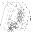
- FIGS 1-4 illustrate a self-contained, fully automated, biological assay apparatus 10 according to an embodiment of the invention.
- the apparatus includes a housing 11; a dispensing platform 12 including a controllable, movable reagent dispensing system 13 disposed in the housing; a reagent supply component 14 that can hold a supply of one or more reagents, in operative connection with the dispensing system, disposed in the housing; a pneumatic manifold 15 that operates to affect the transport of fluid in a fluidic transport layer 16 and a plurality of reservoirs 17 attached to the fluidic transport layer 16 opposite the pneumatic manifold 15, that is removably disposed in the housing 11 in a space shared by the dispensing platform 12, wherein the fluidic transport layer 16, reservoirs 17 and a test sample to be introduced therein are disposed in a space separate from the dispensing platform 12; a pneumatic supply system 18, which functions to provide pneumatic signals (positive and negative (vacuum) pressure) routed through the pneumatic manifold 15
- a self-contained, biological assay apparatus 10 is designed to require an operator of the assay apparatus 10 only to introduce a biological sample of interest into a specific sample input port 33 of a plurality of such ports 33 n on the reservoir layer 17, which covers the fluidic transport layer 16 (with attached film layer 30) and, which altogether are managed by the pneumatic manifold 15, and then initiate a start sequence of the control system 19, whereby the sample is completely and automatically processed through an assay to the assay's end point.
- each sample is separate, within its assay unit, from all other samples, and from the biological assay apparatus throughout the processing sequence.
- the lower limit is one assay unit and there is no particular upper limit.
- the sample is automatically drawn from the sample input reservoir into the fluidic transport layer 16, or reagents are transported by the fluidic transport layer 16 from a separate reservoir to the sample input reservoir 33. All of the processing steps required to analyze the sample are then carried out within either the reservoir layer 17 and/or the fluidic transport layer 16 including amplification via appropriate reactors (e.g., 31, Figures 11 , 12 ) disposed in the fluidic layer 16 or communicating with the fluidic layer 16 via a lumen 44 of the system, without the intervention of an operator.
- appropriate reactors e.g., 31, Figures 11 , 12
- the system maintains separation of the sample from the reagent dispensing system 13, the pneumatic manifold 15, and the pneumatic supply system 18.
- This separation feature eliminates cross-contamination problems that inevitably increase the costs and decrease the reliability of current systems that perform similar tasks but that require the sample move from station to station within an apparatus while it is being processed or that require the dispensing system to impart movement of fluids within a microfluidic system.
- the apparatus 10 includes a housing 11 that is designed to enclose the interior of the system during operation so that the fully automated processing can proceed to completion uninterrupted by an operator.
- the housing 11 also encloses the control system 19, the dispensing platform 12, the reagent supply component 14, and the pneumatic supply system 18, which operates the pneumatic manifold 15.
- Figures 1-4 also depict the reagent dispensing system 13.
- the reagent dispensing system is attached to the X-Y-Z motion control system and together is the dispensing platform 12.
- the dispensing system 13 is comprised of a dispenser needle 23, a large storage loop 25, a small storage loop 26, a solenoid valve 24 for each storage loop 25, 26, and a camera 27.
- the dispenser needle 23 is comprised of a double barrel tube or elongate needle structures of length, L, having different respective, selected bore sizes.
- the smaller barrel (bore) is attached to the small storage loop 26 through a dedicated solenoid valve 24 and the larger barrel is attached to the large storage loop 25 through a dedicated solenoid valve 24.
- one of the reagent dispenser needles has a bore diameter b 1 , where 0.003 ⁇ b 1 ⁇ 0.018 inches (in) and the other reagent dispenser needle has a bore diameter b 2 , where 0.015 ⁇ b 2 ⁇ 0.030 in.
- the camera 27 may have various functions for the self-contained biological analysis system 10.
- One function may be to coordinate the location of the dispenser needle 23 of the dispensing system 13 with the reagent supply component 14 and the reservoir layer 17 attached to the fluidic transport layer 16 so the reagents in the reagent supply component 14 are dispensed into the proper reservoir on the reservoir layer 17.
- Another function is to provide sample and/or analysis information to the control system 19.
- the camera 27 can record the sample's information from an optical source such as a bar code or other distinct optical marking systems known in the art.
- the information from the sample can then inform the control system 19 of proper sample loading and later it may be combined with the resulting analysis.
- the identified and properly loaded sample then is processed by the self-contained biological assay apparatus 10 and the end result recorded by the same camera 27.
- the information can then be communicated to the operator through a control system operator interface.
- the small and large control loops 25, 26 are coils of tubing attached through the solenoid valves 24 to their particular barrel of the double barrel dispensing needle 23.
- the dispensing needle 23 is moved by the X-Y-Z motion control system to the particular reagent in the reagent supply component 14.
- the needle is inserted into the reagent's container and negative pressure is supplied through the small or large storage loop 25, 26 and through an open solenoid valve 24.
- the desired amount of the particular reagent is withdrawn from the reagent's container.
- the X-Y-Z motion control system then transports the dispensing system 13 to the location of a reservoir requiring the reagent.
- Positive pressure is then supplied to the large or small storage loop and the appropriate solenoid valve is opened for it to dispense a metered amount of reagent into the reservoir.
- the dispensing system 13 may then be repositioned to another reservoir requiring the same reagent and the dispensing process repeated until all of the reservoirs requiring a particular reagent are supplied.
- the dispensing needle 23 and the storage loop 25 or 26 used are then cleaned by repeated flushing of the dispensing needle 23 and the tubing of the storage loop 25 or 26 with the appropriate washing fluid.
- the dispensing system 13 is then prepared to transport and supply another reagent when the assay requires it.
- the proper metering of reagents is accomplished by active controlling through control system 19 of the positive or negative pressure supplied to the storage loops 25, 26 and timing the opening and closing of the solenoid valves 24 of the dispensing system 13 while either withdrawing or dispensing reagents.
- the deployment of a single dispensing needle 23 that is automatically cleaned is an advantage since alternative methods of reagent dispensing generally require the use of a pipetter and large numbers of disposable pipette tips.
- the self-contained biological assay apparatus 10 uses a fluidic transport layer 16 that separates the sample from the reagent input reservoirs in the reservoir layer 17 thus avoiding the potential for cross contamination that occurs in alternative systems. Therefore the single dispensing needle system 23 is employed and the need for a pipetter system is not required.
- the dispenser system may be configured as a pipetter system and operate in a similar manner although incorporating disposable pipette tips instead of cleaning the dispenser needle between reagent applications.
- the sample may also be automatically dispensed into the sample input port 33 by the pipette and the pipette tip disposed to avoid cross contamination.
- the pneumatic manifold 15 which is comprised of two subunits 15a and 15b where subunit 15a receives the pneumatic supply from the pneumatic supply system 18 and splits the signals through its integrated pneumatic channels 32 to deliver the pneumatic signals to subunit 15b's pneumatic channels that in turn supply the pneumatic signals to the diaphragms on the underside of the fluidic transport layer, interfaces with a plurality of microfluidic systems (16, 16a, and 17 in combination, referred to hereinafter as an assay unit or, commercially, as a CARD® (Chemistry and Reagent Device)), each CARD having a singular or plural assay capacity.
- a CARD® Chremistry and Reagent Device
- Each CARD further includes a multi-layer, monolithic, polymeric, non-elastomeric microfluidic chip (microfluidic transport layer) 16 that has a given configuration of microfeatures including a plurality of pneumatic signal-actuated diaphragm valves.
- the system further includes a separate, replaceable pneumatic manifold including a plurality of pneumatic ports there through and a plurality of pneumatic channels disposed therein in fluid connection with both the plurality of diaphragm valves and the plurality of pneumatic ports.
- the plurality of pneumatic ports and pneumatic channels have a given configuration specifically corresponding to the given configuration of the plurality of diaphragm valves on the fluidic transport layer 16.
- the fluidic transport layer 16 is removably connected to the pneumatic manifold 15.
- the pneumatic supply system 18 further comprises a plurality of pneumatic connections that provide pneumatic signals to the pneumatic manifold 15, in fluid connection with the plurality of pneumatic ports.
- the plurality of pneumatic connections have a configuration corresponding to the configuration of the plurality of pneumatic ports of the pneumatic manifold 15.
- the pneumatic manifold 15 is removably connected to the pneumatic supply system 18.
- Each multi-layer, monolithic fluidic transport layer 16 further includes a polymeric, non-elastomeric substrate 16a having a plurality of fluid channels 39 disposed therein, each of the fluid channels 39 having an inlet end and an outlet end, and at least one bi-directional diaphragm pump comprising at least three non-elastomeric membrane-based valve structures that are constructed from a single, non-elastomeric, polymeric film layer 30.
- each fluidic transport layer 16 may include an integral or component reservoir layer 17 including at least a sample input reservoir 33 capable of holding a sample and at least reagent reservoir (34) that is capable of holding a reagent material.
- the reservoir layer 17 and its attached fluidic transport layer 16 are removably disposed on the pneumatic manifold 15 so that upon completion of an analysis the combined reservoir layer 17 and fluidic transport layer 16 may be removed and replaced with a different combined reservoir layer 17 and fluidic transport layer 16 that is either unused or has been cleaned and prepared for re-use.
- the pneumatic manifold 15 is also removably disposed on the pneumatic supply system 18 in the housing. The pneumatic manifold 15 may also then be replaced with another pneumatic manifold 15 that is complimentary to another arrangement of combined reservoir layer 17 and fluidic transport layer 16 designed for alternative assays or greater or lesser numbers of assay units of any particular assay.
- the pneumatic manifold 15 may include multi-purpose and/or specific purpose heaters (29, 48 and 48a) used, e.g., to heat the amplification/reaction reactors 31 and/or other reservoirs or channels.
- the multipurpose heater 2301 may be in the form of a laminated copper/aluminum structure 2303 that is mounted on spring-loaded electrical contact pins 2305, which provide electrical contact for resistors 2307 that generate heat that is then conducted through the laminated heater body.
- the contact pins also provide a connection to a temperature sensing device 2309 used to modulate the heater.
- the spring-mounted electrical contacts also provide uniform contact between the heater surfaces and the object to be heated.
- the laminated heater apparatus may be a commercially available metal core (laminated copper/aluminum; e.g., Thermally Conductive PCB Substrate, Laird Technologies, Chesterfield, MO) board.
- the metal core board provides excellent thermal conductivity, which further provides good temperature uniformity with a temperature sensor component built into the circuit layout.
- the pogo contact pins e.g., Spring Contact Probes, Interconnect Devices Incorporated, Kansas City, KS
- the fluidic transport layer 16 interfaces with the pneumatic ports and the heaters 29, 48 and 48a.
- the sample and/or reagents are drawn into the fluidic transport layer 16 and transported there through to undergo various processing steps and analysis steps, involving the reservoir layer 17, amplification reactor(s) 31, and other components such as the heaters 29, 48 and 48a and magnets 49 disposed on the pneumatic manifold 15.
- the reservoir layer 17, or an amplification reactor 31 are separated in their particular assay unit from the other assay units.
- the separation prevents cross contamination of the sample with or from any other assay units, the reagent dispensing system 13, the pneumatic manifold 15, or the pneumatic supply system 18, thereby providing greater analytical reliability and decreased operation costs since the system's cleaning requirements are greatly reduced.
- the pneumatic supply system 18 functions to provide pneumatic signals (positive and negative pressure) routed through the pneumatic manifold 15 to affect the transport of the test sample and the reagents within the fluidic transport layer 16. Its operation is coordinated with the dispensing platform 12 so that when reagents are delivered to particular or common reservoirs on reservoir layer 17 by the dispensing system 13 from the reagent supply component 14 the proper processing procedures occur.
- the pneumatic manifold 15 also may incorporate areas where heating, cooling (accomplished by directing a jet of compressed air , that may or may not be actively cooled, from the pneumatic supply system 18 at the heater, or supplying air flow from a fan), or magnetism may be applied to facilitate a reaction.
- the pneumatic supply system 18 is disposed in operative connection with the pneumatic manifold 15 in the housing 11 in a space separate from the dispensing platform 12 and a control system 19 that is used to control the dispensing platform 12, the pneumatic supply system 18, and any heating, cooling (accomplished by directing a jet of compressed air, that may or may not be actively cooled, from the pneumatic supply system 18 at the heater or supplying air flow from a fan), or magnetism performed by the pneumatic manifold 15 reaction occurring in the fluidic transport layer 16, the reservoir layer 17 or the amplification reactors 31.
- Figure 4 is a perspective view of the self-contained biological assay apparatus 10, which more clearly shows the location of the pneumatic supply system 18 beneath the pneumatic manifold 15.
- the pneumatic supply system 18 is located within the lower portion of the housing 11.
- the pneumatic manifold 15 is removably attached to the pneumatic supply system 18 in order to facilitate easy reconfiguration of the self-contained biological assay unit 10 for assays that require different designs of the fluidic transport layer 16.
- the pneumatic supply system 18 is comprised of a number of subcomponents designed to store, meter and route pneumatic pressure under the direction of the control system 19 through the pneumatic manifold 15 to operate the diaphragms located on the fluidic transport layer 16 of an assay unit.
- Positive and negative pressure is supplied to the positive and negative pressure storage reservoirs 21 through positive and negative pressure regulators 20.
- Positive and negative pressure are in turn metered and supplied to the channels of the pneumatic manifold 15 from the positive and negative pressure storage reservoirs 21 through pneumatic supply solenoids 22 (the tubes leading from the pneumatic supply solenoids 22 to the undersurface of the pneumatic manifold 15 are not shown for clarity (the configuration may also be configured without tubes by having a tubeless solid state interface between the pneumatic supply system 18 and the pneumatic manifold 15)).
- the pressure metering and the opening and closing of the solenoids is managed by control system 19 and supplies the metered pneumatic force to the pneumatic manifold 15, thereby operating the diaphragm pumps located on the fluidic transport layer 16.
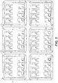
- Figure 5 illustrates an array of six CARDs depicting a "six by four" arrangement of reservoirs, each four assay unit CARD being removably disposed on the pneumatic manifold 15.
- the reservoir layer 17 is covered by a film (not shown) to protect its contents from potential cross contamination by samples in process in adjacent assay units and to prevent the contents of the reservoirs 17 from contaminating the dispensing platform 12, the pneumatic manifold 15, the pneumatic supply system 18, the control system 19, or the housing 11.
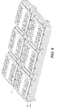
- Figure 6 further illustrates a "six by four" CARD arrangement removably attached to the fluidic transport layer 16 on the pneumatic manifold 15.
- Figure 7 is a top view of the interface between the fluidic transport layer 16 and the pneumatic manifold 15.
- Gaskets 28 are attached to the top of the pneumatic manifold 15 and are designed to isolate the pneumatic forces applied to the film layer 30 ( Figure 15B ) of the fluidic transport layer 16. Terminating within each gasket void is a channel routed through the pneumatic manifold 15 from the pneumatic supply system 18.
- the unbonded portion of the film layer 30 of the fluidic transport layer 16 is then able to be flexed into or out of the gasket void by applied positive and/or negative pressure routed through the pneumatic manifold 15 from the pneumatic supply system 18 and controlled by control system 19.
- the control system 19 can apply the positive or negative pressure sequentially to selected locations, which creates a diaphragm pumping system as described in commonly assigned patent US 7,832,429 .
- a diaphragm pumping system as described in commonly assigned patent US 7,832,429 .
- heaters 29 may be located within the pneumatic manifold 15 that the amplification reactors 31 fit into when the CARD is placed onto the pneumatic manifold 15.
- the amplification reactor 31 is filled with the appropriate reagents and processed sample transported through the fluidic transport layer 16 from various reservoirs in reservoir layer 17.
- the contents of the amplification reactor are then heated and cooled (accomplished by directing a jet of compressed air , that may or may not be actively cooled, from the pneumatic supply system 18 at the heater or supplying air flow from a fan) in a controlled manner through instructions from the control system 19.
- Figure 8A illustrates a perspective view of the layer 15a of a "six by four" arrangement of the pneumatic manifold 15 of the self-contained biological assay apparatus 10.
- Figure 8B illustrates a top layered view of a "six by four" arrangement of the pneumatic manifold 15a of the self-contained biological assay apparatus 10.
- the channels 32 through which the pneumatic signals are routed from the orifices on the bottom of the pneumatic manifold 15 form the pneumatic supply system 18 and the orifices on the layer depicted in 8A.
- Figure 8C illustrates a perspective bottom view of a "six by four" arrangement of the pneumatic manifold 15 of the self-contained biological assay apparatus 10.
- the pneumatic solenoids 22 and the pressure storage reservoirs 21 depicted in Figure 4 supply pneumatic pressure or vacuum to the orifices located on the bottom of the pneumatic manifold 15.
- the pressure storage reservoirs 21 supply metered positive and negative pressure to the pneumatic channels 32 shown in Figure 8B that are fabricated in the pneumatic manifold 15.
- a pneumatic channel 32 is either supplied with metered negative or metered positive pressure depending upon which pressure storage reservoir 21 is attached to the specific pneumatic supply solenoid 22 opened or closed by the control system 19.
- the metering of the pressure is accomplished by adjusting the pressure of pressure storage reservoirs 21, modulating the opening of pneumatic supply solenoids 22 or a combination of both under the management of control system 19
- the pressure supplied to the channel then operates the fluidic transport layer 16 through the gasket interface 28 of the pneumatic manifold 15.
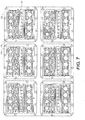
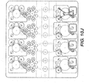
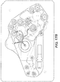
- Figure 9 illustrates a layered top view of a "four assay unit” CARD, with fluidic channels 39 of the fluidic transport layer 16 and amplification reactors 31.
- the figure shows sample input reservoir 33, common preparative and purification reagent reservoir 34, waste reservoir 35, and silica filter reservoir 36 including silica filter retaining ring 36a, which would hold silica filter 36b (not shown for clarity) in the preparation and purification area of a single assay portion of a CARD. It also shows elution reservoirs 37 (left and right), amplification master mix reservoirs 38 (left and right), and amplification reactors 31 (left and right) attached underneath the fluidic transport layer 16 and accessed through a lumen 44. It also shows common reagent input reservoir 40, analysis reservoir 41, and waste reservoir 42 and the perforated ring system 43 used to support the analysis membrane 43 (not shown for clarity) of the analysis portion of a single assay unit of a four assay unit CARD.
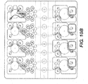
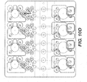
- Figures 10A through 10K generally illustrate a non-limiting, exemplary method of using the device to process and analyze a sample.
- a description of a single assay unit is provided here though there is no particular upper limit to the number of assay units that can process samples either in parallel or serially as samples are provided to the self-contained biological assay apparatus 10.
- the order that individual samples are processed are based upon the capabilities of the control system 19 to manage the pneumatic supply system 18 and the particular arrangement of the pneumatic manifold 15, and the specific reagents supplied by the reagent supply component 14 and delivered by the dispensing system 13.
- a specific assay may require a design of a reservoir layer 17 and its matching fluidic transport layer 16 that interfaces with the pneumatic manifold 15. When all of the matching elements are combined, the process will generally proceed as follows.
- a sample is input into sample input reservoir 33 and the dispensing system 13 provides a cell lysing reagent into common reservoir 34.
- the cell lysing reagent is then pumped to the sample input reservoir 33 and incubated either with or without gentle agitation as described in co-pending application S/N 12/249,872 as "fluffing" (i.e., the repeated actuation of a diaphragm accessing a reservoir to alternatively withdraw and then inject fluid into a reservoir to cause turbulence and mixing), as required by the assay.
- sample input reservoir 33 While the sample is incubating in sample input reservoir 33, an organic alcohol (e.g., ethanol) is dispensed by the dispensing system 13 into common reservoir 34 and pumped to sample input reservoir 33 further increasing the volume in sample input reservoir 33; the larger mixture continues to incubate.
- organic alcohol e.g., ethanol
- the contents of sample input reservoir 33 are pumped onto the top of the silica filter 36b in silica filter reservoir 36 and pulled through the silica filter 36b and the contents pumped to waste reservoir 35.
- an organic alcohol e.g., ethanol
- a wash buffer is dispensed into common reservoir 34 and pumped on top of the silica filter 36b in silica filter reservoir 36, pulled through the silica filter 36b and pumped to waste reservoir 35.
- the same or another wash buffer is dispensed into common reservoir 34 and pumped on top of the silica filter 36b in silica filter reservoir 36, pulled through the silica filter 36b and pumped to waste reservoir 35.
- an elution buffer is then dispensed into common reservoir 34 and pumped directly to waste reservoir 35 to clear the channel of residual lysate, the organic alcohol, and wash buffer.
- Fresh elution buffer is dispensed into common reservoir 34 and pumped on top of the silica filter 36b in silica filter reservoir 36 to clean the reservoir, then it is pumped from the top of the silica filter 36b to waste reservoir 35.
- elution buffer is then dispensed into elution reservoir 37 (right) and pumped up through the bottom of the silica filter 36b in reservoir 36.
- amplification master mix is then dispensed into amplification master mix reservoirs 38 (left and right).
- An initial volume from silica filter reservoir 36 is pumped into elution reservoir 37 (right), then a single pump of material is pumped from silica filter reservoir 36 to amplification master mix reservoir 38 (right).
- the contents of amplification master mix reservoir 38 (right) are then emptied into amplification reactor 31 (right). The same process is repeated on the left side. Then the contents of amplification reactors 31 (left and right) are thermocycled under the control of control system 19 in accordance with the protocols of the particular assay in process.
- a pre-hybridization buffer is dispensed into common reagent reservoir 40 and pumped into amplification reactor 31 (right), then repeated to provide pre-hybridization buffer to amplification reactor 31 (left).
- the temperature in the amplification reactors is then increased to denature the amplicons produced from the earlier thermocycling.
- an appropriate amplicon visualization reagent e.g., horseradish peroxidase ("HRP")
- HRP horseradish peroxidase
- a visualization reagent reactant e.g., tetramethyl benzidine "TMB"
- TMB tetramethyl benzidine
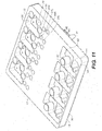
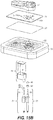
- FIG 11 illustrates a perspective view of a "four assay unit" arrangement of a CARD including the reservoir layer 17, the fluidic transport layer 16 including the film (non-elastomeric membrane or diaphragm) layer 30, and one of the amplification reactors 31 with its attachment system 45, 46 as well as a portion of a perforated securing ring 43 used to suspend the analysis membrane 47 in analysis reservoir 41.
- each exemplary 'quad' CARD has four microarray analysis reservoirs 41 ( Figs. 9 , 11 ), which include a microarray analysis membrane 47 removeably disposed therein.
- An exemplary analysis membrane 47 is made of nylon, nitrocellulose, PVDF or any other appropriate material known in the art.
- the analysis reservoir 41 has a support platform on the bottom of the reservoir or a shelf or shoulder extending about the bottom inner perimeter thereof.
- a perforated, segmented, or indented securing ring may be used to secure the membrane in the analysis chamber.
- Figure 13B shows an exemplary perforated securing ring 43 having channels 1708 for transporting fluid from within the analysis reservoir over the perimeter of the membrane to the bottom of the reservoir and then to outside of the reservoir.
- two securing rings 43 may be used to sandwich the membrane 47 therebetween or as illustrated a support platform slightly smaller than the membrane but not smaller than the inner dimension of the perforated ring 43 may be used to hold the membrane.
- Figure 12 illustrates a side view of an "assay unit" including the reservoir layer 17, the fluidic transport layer 16 including the film layer 30 bounding the channels 39, and one of the amplification reactors 31, which includes a lumen 44 used to fill and empty the amplification reactor.
- an aqueous solution may be repeatedly (20 - 50 times) cycled from low temperatures of approximately 30° C to higher temperatures of approximately 95° C.
- wax, silicone, mineral oil, or some other substance may typically be introduced over the top of the solution to prevent evaporation; however, the use of these materials has certain disadvantages.
- mineral oil is a liquid at room temperature and, therefore, for certain automatic systems it produces handling problems.
- Wax is a solid at room temperature and for automatic systems its melting temperature is very controllable, but wax often impedes the more desirable complex PCR reactions.
- Silicone like mineral oil, is a liquid at room temperature, so it has similar handling problems but it does not impede PCR reactions.
- a substance that could cover the solution automatically when the PCR reaction tube e.g., 31, Fig. 11 , 12
- a controlled mixture of high purity silicone oil with a small amount (a few %) of wax as an additive may be used.
- the mixture consists of approximately 5% wax and 95% silicone oil.
- the wax may be standard PCR wax (e.g., Sigma Aldrich paraffin wax with melting point of 58 - 62 degrees C).
- the mixture is a solid at room temperature and expected storage temperatures.
- the mixture may be placed as a layer of material on the upper inside surface of the PCR tube (31) just below the opening of the tube and above the bottom opening of the lumen 44.
- the mixture melts and covers the surface of the solution preventing evaporation while at the same time it does not have an impeding effect on the reaction.
- the reactants can be removed from underneath the seal via the lumen (44, Fig. 12 ) either before or after the mixture re-hardens upon reducing the temperature in the amplification reactor below the melting point of the mixture.
- the mixture is allowed to cool forming a solid cap over the solution and the lumen 44 withdraws the solution from below the solidified layer.
- Figure 13A illustrates an exploded view of a "four assay unit” CARD including the reservoir layer 17, the fluidic transport layer 16 including its film layer 30, and the amplification reactors 31, which include lumens 44 used to fill and empty the amplification reactors.
- the illustration also shows silica filter holders 36a, the silica filters 36b for the silica filter reservoirs 36 and the perforated securing rings 43 used to suspend the analysis membranes 47 in the analysis chambers.
- Figure 14A-D illustrate an alternative arrangement of a portion of the analysis area of reservoir layer 17 and the fluidic transport layer 16 to which it is attached.
- the alternative arrangement is used to cover the analysis membrane 47 in order to improve contact between the circulating amplicons and the target molecules on the analysis membrane 47 in the analysis reservoir 41.
- the cover may be vented to allow air bubbles to escape from analysis reservoir 41.
- the arrangement also allows for efficient heating of the analysis reservoir 41 by eliminating the step or platform used in the perforated ring arrangement 43 previously illustrated.
- the analysis membrane sits directly on the film layer 30 which in turn is disposed directly over a heating element 48a. Heat applied during an analysis reaction is often an important step in an assay.
- the covered system also allows for a different arrangement of the channels supplying and emptying the analysis reservoir.
- the membrane is on the very bottom of the reservoir the fluid can be washed over the top of the membrane 47 in an alternating pattern.
- an overhang is fabricated in substrate layer 16a of analysis reservoir 41and as shown in Figure 14B channel openings are fabricated under the overhang at each end of the analysis reservoir 41.
- the analysis reservoir 41 is also fabricated so that it is longer than it is wide which combined with the channel openings onto each end allows for an efficient flow over the length of the analysis membrane and further combined with the cover allows for improved contact of the fluid with the surface of the analysis membrane allowing the amplicons in the fluid to more efficiently hybridize with their targets attached to the analysis membrane.
- FIG 14C illustrates an exemplary four assay unit alternative pneumatic manifold 15 and gasket layer 28 that corresponds to the alternative arrangement of the analysis area describe in 14A and 14B.
- Figure 14D illustrates the internal pneumatic channels 32 of pneumatic manifold layer 15b showing how the pneumatic signals introduced into the bottom layer of 15a from the pneumatic supply system 18 are further split and addressed to particular gasket layer 28 voids on the surface of 15b.
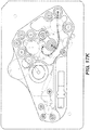
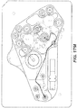
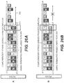
- Figure 15A illustrates an exploded perspective view of an exemplary single assay unit of a pneumatic manifold 15, incorporating pneumatically activated magnet assemblies 51 and a multi-purpose heater 48 coupled thereto, for preparative, amplification, and analysis reaction needs.
- the figure also includes an optional diaphragm layer 53 for the interface between the fluidic transport layer 16 and the pneumatic manifold 15.
- the illustrated system can be "numbered up” (e.g., "Quad CARD®") and attached to a pneumatic supply system 18 to operate multiple assay units in parallel or in random order as instructed by the control system 19.
- the illustrated system provides for the use of magnetism when required during an assay for the manipulation of ferrous, magnetic, or paramagnetic particles as required by any particular assay.
- the particle required may be introduced into a particular reservoir on reservoir layer 17 by the dispenser system 13 and combined with the sample during certain steps of the assay.
- the particles may be included with the sample prior to its loading into the sample input reservoir 33 or, alternatively still, the particles may be pre-loaded into a reservoir or a channel during the manufacture of the fluidic transport layer 16 or the reservoir layer 17.
- the sample with the particles in mixture may be pre-loaded in a reservoir or a channel located over a pneumatic piston assembly (alternatively the piston assembly may be motor or electromagnetically activated) 51 or the sample/particle mixture may be pumped to a reservoir or channel located over a pneumatic piston assembly (alternatively the piston assembly may be motor or electromagnetically activated) 51.
- the reservoir or channel over the pneumatic piston assembly (alternatively the piston assembly may be motor or electromagnetically activated) 51 may be subjected to a magnet 49, located on a magnet holder 50 fixed on the end of a piston rod 52 of the pneumatic piston assembly (alternatively the piston assembly may be motor or electromagnetically activated) 51 by providing positive pressure to the cylinder of the pneumatic piston assembly (alternatively the piston assembly may be motor or electromagnetically activated) 51, which then directs the magnet into place just under heated reservoir 55, or non-heated reservoir 56, or a channel containing the sample/particle mixture.
- the assay When magnetism is delivered to the site with the sample/particle mixture, the assay then takes advantage of the particles' magnetic properties to carry out particular assay requirements; e.g., using the particles for a particular concentration step of biological material attracted to the particle or other common particle dependent assay step known in the art.
- the pneumatically-actuated magnet systems 51 may be incorporated into a region of the pneumatic manifold 15 so that the particles and sample in progress may undergo a heating event in conjunction with a magnetism event.
- a heating event in conjunction with a magnetism event.
- An example of such a case is to use the particles to concentrate an organism out of a larger sample volume. In the case where the organism is alive when it is captured, it can then be subjected to a heating event to cause the organism to express RNA that it would not normally express or that it could not express if it were dead.
- the magnetism is removed by subjecting the cylinder of the pneumatic piston assembly (alternatively the piston assembly may be motor or electromagnetically activated) 51 to negative pressure, thus withdrawing the magnet 49 from a location underneath heated magnetic reservoir 55, and pumping the solution with the particles and the concentrated sample with the organism to another location in order to proceed with extracting the RNA from the organism, and further amplifying the extracted RNA and analyzing the resulting amplicons in a manner consistent with the process described above.
- the piston assembly may be motor or electromagnetically activated
- Figure 15A also illustrates the opportunity to provide heat in a reservoir 54 separate from the amplification reactor 31 in order to denature amplicons prior to analyzing the amplicons, incubate a labeling reaction or otherwise improve the process of a particular reaction. It further illustrates an alternative manner for locating the amplification reactor. Although this illustration does not provide an amplification reactor in a tube and lumen 44 arrangement as earlier described, there is no reason that such a tube and lumen 44 arrangement cannot be utilized with the pneumatic piston assemblies 51 described above. As shown, the interface between the pneumatic manifold 15 and the fluidic transport layer 16 includes an optional diaphragm layer 53 in place of the gasket layer 28 discussed above.
- the diaphragm layer serves the same function of providing an isolated space for the film layer 30 to deflect into when negative pressure is applied to the unbonded region of the film layer 30 by the pneumatic manifold 15 from pneumatic signals routed through the pneumatic channels 32 of the pneumatic manifold 15 attached to the pneumatic supply system 18 under the instructions of control system 19.
- Figure 15B illustrates the same elements as Figure 15A although without the diaphragm layer. Therefore the gasket layer 28 serves the function as described in Figure 7 above and the fluidic transport layer 16 interfaces directly with the pneumatic manifold 15.
- the arrangement without the diaphragm layer is advantageous since the manufacturing and the material costs in both cases are lower in the absence of the diaphragm layer while the performance of assays on the system is no different.
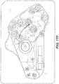
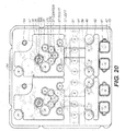
- Figure 16 illustrates a view of a single assay unit for improved rapid detection of sparse targets, non-viable and viable water-borne organisms, and shows functional structures including pneumatically activated magnets 51 and multiple heated reaction sites, as well as the arrangement of reservoirs and channels employed by the system.
- the system illustrates how the pneumatic manifold 15 can be arranged in combination with the fluidic transport layer 16 and its attached reservoir layer 17 so that heat can be delivered to different steps of an assay.
- heat can be employed in a preparative step in heated magnetic separation/concentration/reaction reservoir 55 (where magnetism can also be selectively employed as desired in conjunction with heating in reservoir 55).
- the sample is transported through the fluidic transport layer 16 for further preparative steps of an assay.
- the extracted DNA or RNA is then combined with the amplification master mix and transported through the fluidic transport layer 16 to the amplification reactor 31.
- the reactor is in the plane of the fluidic transport layer 16, though it may also employ a reactor configured as in Figures 11 , 12 and 13 out of the plane of the fluidic transport layer 16.
- the amplicons are produced in the amplification reactor 31, they can be transported to the heated analysis reactor 54 where they can be heated in order to denature and/or label them, or a combination of requirements that may require heating.
- the amplicons are then transported to the analysis reservoir 41 (which also can be configured for heating) for completion of the assay.
- Figures 17A-O further illustrate the exemplary analysis processes as follows: As illustrated in Figure 17A , place sample into reservoir 33/55, dispense buffer and beads into reservoir 33/55 and incubate with gentle agitation by fluffing using the large diaphragm adjacent to reservoir 33/55. Choose temperature and incubation time appropriate for the assay. Raise magnet 49 into place under reservoir 33/55 and then pump contents to waste reservoir 35.
- set multi-purpose heater 48 to the appropriate incubation temperature (if required by the particular assay) and, after an appropriate incubation, lower magnet 49 out of place under reservoir 33/55; dispense wash buffer into reservoir 37/56 and pump it to reservoir 33/55 to re-suspend the beads, gently agitate, and set multipurpose heater 48 to appropriate incubation temperature and time (as required by the particular assay); dispense lysis buffer into common reagent reservoir 34 (lysis buffer), pump the lysis buffer to reservoir 33/55, and agitate by fluffing as above and heat as required by the particular assay; dispense an organic alcohol (e.g., ethanol) into common reagent reservoir 34 (ethanol) and pump it to reservoir 33/55 and agitate by fluffing as above and heat as required by the particular assay.
- an organic alcohol e.g., ethanol
- lower magnet 49 out of place under reservoir 37/56.
- Gently agitate and incubate as appropriate. Raise magnet 49 into place under reservoir 37/56 and pump the contents of reservoir 37/56 to waste reservoir 35.
- Lower magnet 49 out of place under reservoir 37/56. Dispense the same or another wash buffer into reservoir 37 (wash buffer B) and pump the contents of reservoir 37 (wash buffer B) into reservoir 37/56 to re-suspend the beads.
- Gently agitate and incubate as appropriate.
- lower magnet 49 out of place under reservoir 37/56.
- any other required reagents into reservoir 54 (the heated analysis reservoir) as required. Agitate, heat and incubate the contents of reservoir 54 (the heated analysis reservoir) as required. Pump all or a portion of the contents of reservoir 54 (the heated analysis reservoir) into reservoir 41(analysis reservoir) to progress through an analysis of the contents of reservoir 54 (the heated analysis reservoir). Dispense running buffer into reservoir 41 (running buffer) and when all of the contents earlier pumped to reservoir 41 (analysis reservoir) are consumed pump the contents of reservoir 41 (running buffer) into reservoir 41(analysis reservoir) to complete the assay. Finally, optically analyze the results displayed on the filter in reservoir 41 (analysis reservoir).
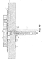
- Figure 18 illustrates a side cross sectional view of the pneumatic manifold 15 with integrated pneumatic piston assemblies 51, one of which is located in the multi-purpose heater assembly 48 and one of which is located in the preparative area of the system.
- the figure specifically shows the internal components of the pneumatic piston assembly (alternatively the piston assembly may be motor or electromagnetically activated) 51 for the preparative area of the system.
- Figure 19 illustrates a side cross sectional view of the pneumatic manifold 15 with integrated pneumatic piston assembly (alternatively the piston assembly may be motor or electromagnetically activated) 51 located in the multipurpose heater assembly 48, and its internal components.
- the piston assembly may be motor or electromagnetically activated 51 located in the multipurpose heater assembly 48, and its internal components.
- Figure 20 shows a layered top view of a double assay unit arrangement which shows exemplary alternative functions of the pneumatic manifold 15 incorporating a pneumatically activated magnet assembly 51 targeting a magnetic separation/concentration channel area 57 instead of a reservoir as described in Figures 17A-O , and including the arrangement of the reservoirs and channels employed by the system.
- Figures 21A-K further illustrate the exemplary analysis processes as follows: As illustrated in Figure 21A , place sample into sample input reservoir 33, dispense enzyme into common reagent reservoir 34 and pump it to sample input reservoir 33. Incubate with gentle agitation. Dispense lysis buffer into common reagent reservoir 34 and pump it to sample input reservoir 33. Incubate with gentle agitation. Dispense beads into common reagent reservoir 34 and pump it to sample input reservoir 33. Incubate with gentle agitation. Dispense an organic alcohol (e.g. isopropanol) into common reagent reservoir 34 and pump it to sample input reservoir 33 and incubate it with gentle agitation.
- an organic alcohol e.g. isopropanol
- dispense amplification master mix into reservoirs 38L and 38R dispense amplification master mix into reservoirs 38L and 38R.
- the master mix dispensed into the separate reservoirs may or may not contain the same primers depending upon the assay.
- the original sample is now split into two aliquots.
- the sample may remain as a single aliquot or be split into more than two aliquots depending on the assay in particular and the layout of available reservoirs, channels, and amplification reactors to accommodate further splitting of the sample.
- Pump the solution in reservoir 37L and amplification master mix reservoir 38L into the amplification reactors 31L and 31R (two are depicted for the left side of the assay unit though only a single amplification reactor is necessary and more than two are possible). Repeat for the right side of the assay unit. Incubate at appropriate temperatures and times for amplification.
- an appropriate amplicon visualization reagent e.g., horseradish peroxidase ("HRP")
- HRP horseradish peroxidase
- HRP horseradish peroxidase
- a visualization reagent reactant e.g., tetramethyl benzidine "TMB"
- TMB tetramethyl benzidine
- FIGS 24-25 illustrate a non-limiting, exemplary process for automatically analyzing a tissue specimen using a CARD apparatus as described herein.
- Figure 45 shows that using the CARD configuration shown in Figure 20 , and according to the process shown in Figures 21-22 , DNA was successfully purified, eluted and amplified.
- the bands shown on the gel are amplified 25S rRNA from Candida (yeast that can cause sepsis).
- the column headings are -Ctl which denotes a benchtop negative control. +Ctl is the benchtop positive control.
- S1 - S4 are four CARD runs.
- the white box results for each S1 - S4 are from an aliquot removed from the CARD and amplified prior to the second step of the purification.
- the nucleic acid was first purified, then eluted (there were 2 stages to the purification and 2 elutions : one from the first stage to the second stage and then elution from the second stage) then amplified, then run on a gel.
- the results confirm that the second stage of the purification provides a marked improvement of the target's amplification.
- the primer amplified the 25S rRNA from Candida which was spiked into a whole blood sample.
- the tissue sample is dissected with a 3 mm diameter cutter.
- the cutter is then inserted into a sample reservoir whereupon operating the cutter plunger, the dissected sample is transferred to the analysis chamber. More specifically, with reference to Fig.
- the sample is loaded as described immediately above; a controller dispenses lysis buffer/proteinase K into the reagent reservoir; the lysis buffer/proteinase K is pumped into the sample reservoir; the mixture is circulated; the controller dispenses ethanol into the reagent reservoir; ethanol is mixed with the reaction solution; the reaction solution is pumped into the purifier on top of the silica filter; and the reaction solution is pumped through the silica filter into the waste reservoir via the silica membrane.
- a screen may be inserted into the reservoir prior to the insertion of the sample so that the tissue passes through the screen in order to increase the surface area of the specimen for the reagents to react more efficiently with the specimen.
- Figure 22 illustrates an exploded view of a double assay unit arrangement of a channel style magnetic separation/concentration system showing the reservoir layer 17, the fluidic transport layer 16, the film layer 30, and the out of plane amplification reactors 31 showing their component parts.
- Figure 22 also includes the silica filter system 36a and 36b.
- the invention provides a method of amplifying and/or isolating nucleic acid molecules of interest (also referred to herein as "nucleic acids of interest,” “target nucleic acids,” “target polynucleotides”).
- An isolated nucleic acid molecule is a nucleic acid molecule (or “nucleic acid”) that is separated from other nucleic acid molecules that are present in the natural source of the nucleic acid molecule.
- an "isolated" nucleic acid is free of nucleic acid sequences (e.g., protein encoding sequences) that naturally flank the nucleic acid (i.e., sequences located at the 5' and 3' ends of the nucleic acid) in the genomic DNA of the organism from which the nucleic acid is derived.
- the isolated nucleic acid is free of intron sequences.
- Nucleic acids of interest refer to molecules of a particular polynucleotide sequence of interest.
- Such nucleic acids of interest include, but are not limited to DNA molecules such as genomic DNA molecules, cDNA molecules and fragments thereof, including oligonucleotides, expressed sequence tags ("ESTs”), sequence tag sites (“STSs”), etc.
- ESTs expressed sequence tags
- STSs sequence tag sites
- Nucleic acids of interest that may be analyzed by the methods of the invention also include RNA molecules such as, but by no means limited to messenger RNA (mRNA) molecules, ribosomal RNA (rRNA) molecules, cRNA (i.e., RNA molecules prepared from cDNA molecules that are transcribed in vivo) and fragments thereof.
- the isolated nucleic acid molecule can contain less than about 5 kb, 4 kb, 3 kb, 2 kb, 1 kb, 0.5 kb or 0.1 kb of nucleotide sequences that naturally flank the nucleic acid molecule in genomic DNA of the cell from which the nucleic acid is derived.
- an isolated nucleic acid molecule, such as a cDNA molecule can be substantially free of other cellular material, of culture medium when produced by recombinant techniques, or of chemical precursors or other chemicals when chemically synthesized.
- the nucleic acids of interest can be DNA or RNA or chimeric mixtures or derivatives or modified versions thereof.
- the nucleic acid can be modified at the base moiety, sugar moiety, or phosphate backbone, and may include other appending groups or labels.
- the nucleic acid can comprise at least one modified base moiety which is selected from the group including but not limited to 5-fluorouracil, 5-bromouracil, 5-chlorouracil, 5-iodouracil, hypoxanthine, xanthine, 4 acetylcytosine, 5-(carboxyhydroxylmethyl) uracil, 5-carboxymethylaminomethyl-2-thiouridine, 5-carboxymethylaminomethyluracil, dihydrouracil, beta-D-galactosylqueosine, inosine, N6-isopentenyladenine, 1-methylguanine, 1-methylinosine, 2,2-dimethylguanine, 2-methyladenine, 2-methylguanine, 3-methylcytosine, 5-methylcytosine, N6-adenine, 7-methylguanine, 5-methylaminomethyluracil, 5-methoxyaminomethyl-2-thiouracil, beta-D-mannosylqueo
- modified base moiety
- the nucleic acid can comprise at least one modified sugar moiety selected from the group including but not limited to arabinose, 2-fluoroarabinose, xylulose, and hexose.
- the nucleic acid can comprise at least one modified phosphate backbone selected from the group including but not limited to a phosphorothioate, a phosphorodithioate, a phosphoramidothioate, a phosphoramidate, a phosphordiamidate, a methylphosphonate, an alkyl phosphotriester, and a formacetal or analog thereof.
- a modified phosphate backbone selected from the group including but not limited to a phosphorothioate, a phosphorodithioate, a phosphoramidothioate, a phosphoramidate, a phosphordiamidate, a methylphosphonate, an alkyl phosphotriester, and a formacetal or analog thereof.
- Nucleic acids for use as primers, probes, or templates may be obtained commercially or derived by standard methods known in the art, e.g., by use of an automated DNA synthesizer (such as those commercially available from Biosearch Technologies, Inc., Novato, CA; Applied Biosystems, Foster City, CA, etc.) and standard phosphoramidite chemistry; or by cleavage of a larger nucleic acid fragment using non-specific nucleic acid cleaving chemicals or enzymes or site-specific restriction endonucleases.
- an automated DNA synthesizer such as those commercially available from Biosearch Technologies, Inc., Novato, CA; Applied Biosystems, Foster City, CA, etc.
- standard phosphoramidite chemistry or by cleavage of a larger nucleic acid fragment using non-specific nucleic acid cleaving chemicals or enzymes or site-specific restriction endonucleases.
- probes hybridize to nucleic acids from the species from which the sequence is desired, for example, hybridization to nucleic acids from genomic or DNA libraries from the species of interest.
- a nucleic acid molecule is used as a probe that is complementary to, or hybridizable under moderately stringent conditions to, an amplified, isolated nucleic acid of interest.
- a nucleic acid molecule is used as a probe that hybridizes under moderately stringent conditions to, and is at least 95% complementary to, an amplified nucleic acid of interest.
- a nucleic acid molecule is used as a probe that is at least 45% (or 55%, 65%, 75%, 85%, 95%, 98%, or 99%) identical to a nucleotide sequence of interest or a complement thereof.
- a nucleic acid molecule is used as a probe that comprises a fragment of at least 25 (50, 75, 100, 125, 150, 175, 200, 225, 250, 275, 300, 325, 350, 375, 400, 425, 450, 500, 550, 600, 650, 700, 800, 900, 1000, 1200, 1400, 1600, 1800, 2000, 2400, 2600, 2800, 3000, 3200, 3400, 3600, 3800, or 4000) nucleotides of a nucleic acid of interest or a complement thereof.
- a nucleic acid molecule is used as a probe that hybridizes under moderately stringent conditions to an amplified nucleic acid molecule having a nucleotide sequence of interest, or a complement thereof.
- a nucleic acid molecule is used as a probe that can be at least 25, 50, 75, 100, 125, 150, 175, 200, 225, 250, 275, 300, 325, 350, 375, 400, 425, 450, 500, 550, 600, 650, 700, 800, 900, 1000, 1200, 1400, 1600, 1800, 2000, 2200, 2400, 2600, 2800, 3000, 3200, 3400, 3600, 3800, or 4000 nucleotides in length and hybridize under moderately stringent conditions to an amplified nucleic acid molecule of interest or a complement thereof.
- Nucleic acids that can be used as probes (or templates) for detecting an amplified nucleic acid of interest can be obtained by any method known in the art, e.g., from a plasmid, by polymerase chain reaction (PCR) using synthetic primers hybridizable to the 3' and 5' ends of the nucleotide sequence of interest and/or by cloning from a cDNA or genomic library using an oligonucleotide probe specific for the nucleotide sequence.
- Genomic clones can be identified by probing a genomic DNA library under appropriate hybridization conditions, e.g., high stringency conditions, low stringency conditions or moderate stringency conditions, depending on the relatedness of the probe to the genomic DNA being probed.
- high stringency hybridization conditions may be used; however, if the probe and the genomic DNA are from different species, then low stringency hybridization conditions may be used. High, low and moderate stringency conditions are all well known in the art.
- Amplified nucleic acids of interest can be detectably labeled using standard methods known in the art.
- the detectable label can be a fluorescent label, e.g., by incorporation of nucleotide analogs.
- Other labels suitable for use in the present invention include, but are not limited to, biotin, imminobiotin, antigens, cofactors, dinitrophenol, lipoic acid, olefinic compounds, detectable polypeptides, electron rich molecules, enzymes capable of generating a detectable signal by action upon a substrate, and radioactive isotopes.
- Preferred radioactive isotopes include, 32P, .35S, 14C, 15N and 125I, to name a few.
- Fluorescent molecules suitable for the present invention include, but are not limited to, fluorescein and its derivatives, rhodamine and its derivatives, texas red, 5'-carboxy-fluorescein (“FMA”), 2',7'-dimethoxy-4',5'-dichloro-6-carboxy-fluorescein (“JOE”), N,N,N',N'-tetramethyl-6-carboxy-rhodamine (“TAMRA”), 6'-carboxy-X-rhodamine (“ROX”), HEX, TET, IRD40 and IRD41.
- FMA fluorescein and its derivatives
- rhodamine and its derivatives texas red
- FMA 5'-carboxy-fluorescein
- JE 2',7'-dimethoxy-4',5'-dichloro-6-carboxy-fluorescein
- TAMRA N,N,N',N'-te
- Fluorescent molecules that are suitable for the invention further include: cyamine dyes, including but not limited to Cy2, Cy3, Cy3.5, Cy5, Cy5.5, Cy7 and FluorX; BODIPY dyes, including but not limited to BODIPY-FL, BODIPY-TR, BODIPY-TMR, BODIPY-630/650, and BODIPY-650/670; and ALEXA dyes, including but not limited to ALEXA-488, ALEXA-532, ALEXA-546, ALEXA-568, and ALEXA-594; as well as other fluorescent dyes known to those skilled in the art.
- cyamine dyes including but not limited to Cy2, Cy3, Cy3.5, Cy5, Cy5.5, Cy7 and FluorX
- BODIPY dyes including but not limited to BODIPY-FL, BODIPY-TR, BODIPY-TMR, BODIPY-630/650, and BODIPY-650/670
- ALEXA dyes including
- Electron rich indicator molecules suitable for the present invention include, but are not limited to, aferritin, hemocyanin, and colloidal gold.
- an amplified nucleic acid of interest may be labeled by specifically complexing a first group to it.
- a second group, covalently linked to an indicator molecule and which has an affinity for the first group, can be used to indirectly detect the target polynucleotide.
- compounds suitable for use as a first group include, but are not limited to, biotin and iminobiotin.
- nucleic acids of interest that are amplified and analyzed (e.g., detected) by the methods of the invention can be contacted to a probe or to a plurality of probes under conditions such that polynucleotide molecules having sequences complementary to the probe hybridize thereto.
- a probe refers to polynucleotide molecules of a particular sequence to which nucleic acid molecules of interest having a particular sequence (generally a sequence complementary to the probe sequence) are capable of hybridizing so that hybridization of the target polynucleotide molecules to the probe can be detected.
- the polynucleotide sequences of the probes may be, e.g., DNA sequences, RNA sequences or sequences of a copolymer of DNA and RNA.
- the polynucleotide sequences of the probes may be full or partial sequences of genomic DNA, cDNA, mRNA or cRNA sequences extracted from cells.
- the polynucleotide sequences of the probes may also be synthesized, e.g., by oligonucleotide synthesis techniques known to those skilled in the art.
- the probe sequences can also be synthesized enzymatically in vivo, enzymatically in vitro (e.g., by PCR) or non-enzymatically in vitro.
- the probes used in the methods of the present invention are immobilized to a solid support or surface such that polynucleotide sequences that are not hybridized or bound to the probe or probes may be washed off and removed without removing the probe or probes and any polynucleotide sequence bound or hybridized thereto.
- Methods of immobilizing probes to solid supports or surfaces are well known in the art.
- the probes will comprise an array of distinct polynucleotide sequences bound to a solid (or semi-solid) support or surface such as a glass surface or a nylon or nitrocellulose membrane.
- the array is an addressable array wherein each different probe is located at a specific known location on the support or surface such that the identity of a particular probe can be determined from its location on the support or surface.
- the method described in WO 2009/049268 A1 by Zhou et al. can be used to immobilize nucleic acid probes to a solid support or surface.
- the probes used in the invention can comprise any type of polynucleotide
- the probes comprise oligonucleotide sequences (i.e., polynucleotide sequences that are between about 4 and about 200 bases in length, and are more preferably between about 15 and about 150 bases in length).
- shorter oligonucleotide sequences are used that are between about 4 and about 40 bases in length, and are more preferably between about 15 and about 30 bases in length.
- a more preferred embodiment of the invention uses longer oligonucleotide probes that are between about 40 and about 80 bases in length, with oligonucleotide sequences between about 50 and about 70 bases in length (e.g., oligonucleotide sequences of about 60 bases in length) being particularly preferred.
- CARD-based diagnostic assays can be used for many different applications in which bench-top based assays are currently used.
- the design of the plastic CARD permits the incorporation of all necessary microfluidic networks, valves, pumps and reservoirs on a simple, inexpensive disposable microfluidic device. Since all assay functions (i.e., flow and mixing rates, temperature control, including thermocycling, resident times, etc.) are easily controlled by software, sophisticated multiplex PCR assays can be easily performed by individuals of varying skill level.
- CARDs can be inserted in either a portable, battery operated POC controller or into a higher throughput EncompassMDxTM workstation. Regardless of the format selected, however, ease-of-performance is achieved.
- the CARD can be adapted by the skilled artisan to assay for any nucleic acid sequence of interest through choice of primer for amplification and choice of probe for detection.
- the CARD can be used for conducting molecular diagnostics assays, which can provide a basis for the management of potential disease states based upon an individual's genomic background.
- the CARD can be used for conducting screens for pharmacogenomic sensitivity, e.g., genetic predisposition for sensitivity to a drug, pharmaceutical composition, chemical or compound of interest.
- pharmacogenomic sensitivity e.g., genetic predisposition for sensitivity to a drug, pharmaceutical composition, chemical or compound of interest.
- the CARD can be used for conducting oncogenic screening assays, i.e., screening for a nucleic acid of interest that is associated with predisposition for cancer.
- the CARD can be used for conducting screening assays for infectious disease agents, pathogens or sepsis.
- the CARD can be used for analysis of single nucleotide polymorphisms (SNPs) for oncology purposes, pharmacogenomic purposes, companion diagnostics (dosing or other needs specific to a particular pharmaceutical compound) or to detect communicable or noncommunicable infectious diseases.
- SNPs single nucleotide polymorphisms
- the CARD can be used for industrial or environmental assays for organisms of interest that are infectious to humans, animals or plants or for spoilage organisms in processed foods or non-processed foods.
- the CARD can be used industrially for conducting assays for monitoring recreational water (beaches, pools water parks, etc.) or water treatment systems for drinking water, ballast water or treated waste water.
- the CARD can be used for conducing screening assays for sparse target nucleic acids distributed in a large volume of liquid.
- the CARD can be used for conducing screening assays for sparse target nucleic acids wherein the sparse targets are to be distinguished from a high background of non-target nucleic acids in a sample.
- the CARD can be easily adapted to have multiple amplification reactors (e.g., 31, Figures 11 , 12 ) that sequester competing primers and that feed into a single analysis reservoir 41, so that multiple amplification reactions can be conducted concurrently on nucleic acids from a single sample.
- multiple amplification reactors e.g., 31, Figures 11 , 12
- the CARD can be adapted by the skilled artisan to perform any thermally mediated nucleic acid amplification known in the art including but not limited to: polymerase chain reaction (PCR), reverse-transcriptase (RT-) PCR, Rapid Amplification of cDNA Ends (RACE), rolling circle amplification, Nucleic Acid Sequence Based Amplification (NASBA), Transcript Mediated Amplification (TMA), Ligase Chain Reaction, transcription-associated amplification (TAA), Cold PCR and non-enzymatic amplification technology. (NEAT).
- PCR polymerase chain reaction
- RT- reverse-transcriptase
- RACE Rapid Amplification of cDNA Ends
- NASBA Nucleic Acid Sequence Based Amplification
- TMA Transcript Mediated Amplification
- TAA transcription-associated amplification
- Cold PCR and non-enzymatic amplification technology.
- the CARD can be heated to test for viability of a detected organism (e.g., the presence of heat-shock associated RNA expressed by the organism). Heating can also be used to regulate the stringency of hybridization in analyses such as the detection of single nucleotide polymorphisms (SNPs).
- SNPs single nucleotide polymorphisms
- the CARD can be adapted by the skilled artisan to accommodate any analytic or detection method for amplicons known in the art, including but not limited to: colorimetric, fluorescent colorimetric, chemiluminescence, electrochemical, electrophoretic, lateral flow, protein microarray, nucleic acid microarray, fluorescence detection methods or various combinations of the detection methods listed above.
- This example demonstrates a specific embodiment of a pharmacogenomic assay for warfarin sensitivity that has been fully integrated and automated on the CARD.
- Reverse dot blot RDB
- the protocol described below can be easily adapted by the skilled practitioner to assay for any single nucleotide polymorphism (SNP) of interest through choice of primers and probes, and can be used for other assays, e.g., oncogenic screening assays.
- SNP single nucleotide polymorphism
- assays conducted on the CARD comprise the following steps:
- PCR amplification is employed in this embodiment, any thermally mediated nucleic acid amplification known in the art can be performed using the above approach, including but not limited to: : polymerase chain reaction (PCR), reverse-transcriptase (RT-) PCR, Rapid Amplification of cDNA Ends (RACE), rolling circle amplification, Nucleic Acid Sequence Based Amplification (NASBA), Transcript Mediated Amplification (TMA), Ligase Chain Reaction, transcription-associated amplification (TAA), Cold PCR and non-enzymatic amplification technology. (NEAT).
- PCR polymerase chain reaction
- RT- reverse-transcriptase
- RACE Rapid Amplification of cDNA Ends
- NASBA Nucleic Acid Sequence Based Amplification
- TMA Transcript Mediated Amplification
- TAA transcription-associated amplification
- Cold PCR and non-enzymatic amplification technology.
- RDB filter blocking is performed during thermocycling so that the two steps are coordinated with the completion of the amplification.
- Example 2 CARD-Based Methods for Rapid and Automatic Detection of Single Nucleotide Polymorphisms (SNPs)
- This example demonstrates use of the CARD for the evolving molecular diagnostics industry that incorporates low cost, CARD technology to analyze clinical raw samples. Once a raw specimen is introduced into the CARD, all assay functions, including cell lysis, nucleic acid purification, multiplex PCR, and end-point analysis, are automatically performed.
- the CARD was used in a pharmacogenomic assay to detect single nucleotide polymorphisms (SNPs) associated with warfarin sensitivity.
- SNPs single nucleotide polymorphisms
- Raw buccal swab samples from twenty individual volunteers were analyzed and the SNP profiles, identified by the warfarin sensitivity assay carried out on the CARD, were confirmed via bi-directional DNA sequencing.
- the pharmacogenomics protocol described below can be easily adapted by the skilled practitioner to assay for any nucleic acid sequence or SNP of interest through choice of primers and probes.
- Such an assay could be used, for example, to screen for viral pathogens, for oncogenes or other genetic mutations, variants or markers of interest, and virtually any cell or tissue can be assayed.
- molecular diagnostics have expanded greatly since its inception in the early 1980s, particularly as a means to permit the detection of slow growing or fastidious bacteria responsible for infectious diseases.
- the detection of viral pathogens, including viral load testing has also been significantly improved by molecular diagnostics.
- molecular diagnostics As more data have become available regarding the human genome, the use of molecular diagnostics in pharmacogenomic, companion diagnostics, and other personalized medicine applications continues to gain momentum.
- the need for highly trained personnel and expensive capital equipment has restricted the use of molecular diagnostics to specialized laboratories or central labs suitably equipped and staffed.
- sample-to-results platforms
- sample preparation steps and/or equipment
- pre-preparation of the sample prior to introduction into the system to achieve gene amplification and detection.
- sample-to-results a platform has been developed that integrates all required sample preparation, assay, and detection steps into a single, inexpensive disposable plastic device capable of achieving fully automated molecular diagnostic testing.
- CARD demonstrated in this example requires only the introduction of a raw specimen, with all subsequent steps performed automatically.
- the device's low cost of both capital equipment and disposables, as well as the absence of any "hands on” efforts, will help make molecular diagnostics a reality in the entire spectrum of critical and point-of-care testing.
- Bench top assays were optimized to establish various parameters that were then converted to the fully automated platform of the CARD. Primers and probes were designed, using methods known in the art, for amplification and capture, respectively. This could also involve optimization of standard chemical lysis and nucleic acid purification protocol if any of the organisms being analyzed were too tough to be lysed.
- NCBI National Center for Biotechnology
- Primers and probes were designed using CLC Sequence Viewer (www.clcbio.com), Integrated DNA Technologies SciTools, (www.idtdna.com/scitools/) and NCBI Primer Blast (www.ncbi.nlm.nih.gov/tools/primer-blast) using standard methods known in the art. All primers and probes were synthesized at Integrated DNA Technologies (Coralville, IA). All microbial and viral DNAs were purchased from the American Type Culture Collection (ATCC, Manassas, VA).
- De-identified buccal swabs were obtained from volunteers following informed consent and cells were lysed and DNA extracted. DNA was subjected to amplification on the CARD using primers designed to amplify the regions surrounding three individual SNPs known to inform warfarin sensitivity CYP2C9*2, CYP2C9*3, and VKORC1*2 (27-32).
- the CYP2C9*2 and CYP2C9*3 SNPs correspond to mutations in the cytochrome P450 gene
- the VKORC1*2 corresponds to a mutation in the vitamin K epoxide reductase complex subunit 1 gene.
- the DNA was separated into two distinct PCR reactions; one mix contained primers to amplify the regions surrounding both CYP2C9 mutations and the other mix contained primers to amplify the region surrounding the VKORC1*2 mutation.
- the amplicons from both reaction mixes were mixed, denatured, and then moved to a chamber containing probes covalently linked to the membrane filters. The denatured amplicons were annealed to the capture probes in the presence of buffer, dNTPs including biotinylated dUTP, magnesium ions, and DNA polymerase lacking the 3'-5' exonuclease proof-reading function (e.g., Vent Polymerase, New England Biolabs, Ipswich, MA).
- the immobilized probes approximately 20 nucleotides long, contained the informative nucleotide at their 3' termini. Under these conditions the denatured and annealed amplicon strand behaves as the template, while the solid-phase probe represents the "primer" to be extended.
- DNA synthesis occurs incorporating dNTPs including biotinylated dUTP.
- dNTPs including biotinylated dUTP.
- thermocycling step of the primer extension assay is performed in the analysis reservoir 41 (see Figures 14A-C ).
- This assay run on the CARD was designed to perform genotyping analysis (warfarin sensitivity assay) by identifying three separate SNPs known to influence the metabolism of warfarin.
- This single (VKORC1*2) and multiplex (CYP2C9*2 and CYP2C9*3) PCR assays were designed to amplify the regions surrounding each SNP and then the denatured amplicons were subjected to primer extension assay to genotype each allele.
- the warfarin sensitivity assay distinguishes between the various alleles found across the three distinct warfarin-related SNPs.
- PCR-amplified DNA sequences were denatured and allowed to hybridize to specific capture probes immobilized on membrane filters.
- the capture probes ultimately served as the primers to be extended using the amplicons as templates.
- Incorporation of biotinylated dUTP along the primer extended sequences results in streptavidinylated HRP binding and color detection as described in the Materials and Methods.
- Figure 27 is a representative image demonstrating how the genotypes were read off of the primer extension filters
- Figure 28 shows the 7 different genotypes that were obtained from the 20 individuals.
- the three possible genotypes that exist for each of the three SNPs identified can be detected by eye and/or established by determining the ratio of signal intensity of the individual spots.
- the genotypes were originally read by at least two different individuals. These results were confirmed with bi-directional sequencing as well as with image analysis as described in Materials and Methods above.
- the warfarin sensitivity assay in this example demonstrates the versatility of the CARD. Regardless of the assay(s) performed, only one "manual" (user conducted) step is required (i.e., initial introduction of the "raw” sample), with all subsequent steps computer automated. Owing to its ease of performance and interpretation of results, this assay will be useful in POC settings in which physicians wish to use genomic data, along with other clinical information, to help establish the correct initial dosing of warfarin.
- Example 3 CARD-based Automated Human Papilloma Virus (HPV) Assay
- This example demonstrates a specific embodiment of a human papilloma virus (HPV) assay that has been fully integrated and automated on the CARD.
- HPV human papilloma virus
- a vaginal swab is collected in a suitable transport media, which allows for extended room temperature storage, if necessary.
- the transport media can be, e.g., PBS buffer, in which the sample will be immediately introduced into the CARD for analysis.
- the transport media can also be is any type of solution known in the art that prevents DNA degradation so that the sample can be held for later use.
- This example demonstrates a method for rapidly, easily and automatically detecting and distinguishing at least 20 types of clinically relevant human papilloma virus (HPV) directly from clinical samples on the CARD, using the protocol discussed above in Example 3.
- HPV human papilloma virus
- Cervical cancer is the leading cause of cancer-related deaths among women in low-income countries and is the second leading cause of cancer-related deaths for women on a worldwide basis.
- FDA-approved molecular diagnostics none are capable of distinguishing the various HPVs other than to classify them as "high” or "low” risk types.
- the C-33A human cervical carcinoma cell line purchased from the American Type Culture Collection (ATCC, Manassas, VA), was grown, and maintained in Eagles Minimal Essential Media containing 10% fetal bovine serum at 37 °C in a CO2 water-jacketed incubated. Cells were grown to confluence, collected either via scraping directly into PBS, or through trypsinization followed by counting of cells. Approximately 5 million cells (equivalent to 10 million genomes) were harvested and lysed followed by purification of genomic DNA using a Qiagen DNeasy kit (Qiagen, Valencia, CA). Concentration of nucleic acids was determined via absorbance at 260 nm. Purified nucleic acids were stored at -20 °C..
- Chimeric plasmid DNA containing HPV genomes were purchased from American Type Culture Collection (ATCC, Manassas, VA) and transformed into DH5 ⁇ E. coli bacteria. Cultures were expanded, and plasmid DNA was purified using Qiagen Plasmid Mini Kit (Qiagen, Valencia, CA). Concentration of DNA was determined via absorbance at 260 nm, and DNA was diluted to 1E6 copies per ⁇ l. Plasmid DNA stocks were stored at -20 °C.
- the HPV L1 gene primer set was designed based on the HPV region corresponding to the 3' end of the L2 gene and the 5' end of the L1 gene, originally described by Yoshikawa, and then further elaborated on by others ( Yoshikawa H, Kawana T, Kitagawa K, Mizuno M, Yoshikura H, Iwamoto A: Detection and typing of multiple genital human papillomaviruses by DNA amplification with consensus primers.
- HPV type The sequence for each specific HPV type was obtained from the National Center for Biotechnology information (www.ncbi.nlm.nih.gov).
- HPV type and corresponding accession number were as follows: 6:NC_000904; 11:M14119; 16:NC_001526; 18:NC_001357; 31:J04353; 33:M12732; 35:M74117; 39:M62849 M38185; 42:M73236; 43:AJ620205; 44:U31788; 45:X74479; 51:M62877; 52:X74481; 53:NC_001593; 56:EF177177; 58:D90400; 59:X77858; 66:U31794; 68:DQ080079.
- the human beta-globin gene was chosen as an internal positive control necessary to confirm successful nucleic acid purification from clinical samples.
- the forward and reverse primers were designed as follows: 5'-GAA TAA CAG TGA TAA TTT CTG GG-3' and 5'-GAA GAT AAG AGG TAT GAA CAT GA-3' (SEQ ID NO:21), respectively.
- the amino-terminated beta-globin capture probe was: 5'-ATC GAG CTG AAG GGC ATC GAC TTC AA-3' (SEQ ID NO:22).
- J Virol Methods 2007, 140(1-2):32-42 ) were performed in which PCR was performed for 10 cycles annealing at a lower temperature, and the for the remaining 25-35 cycles, annealing is performed at a higher temperature.
- PCR was performed using 1000 copies of HPV 16 containing plasmid over a background of 32 ng C33A purified nucleic acid and optimized for MgCl2 concentration, primer concentration, buffer constituents, and annealing temperatures for each of the two annealing temperatures.
- PCR was ultimately optimized under the following conditions: 10 mM Tris-HCl, pH 9, 50 mM KCl, 100 ⁇ g/ml BSA, 1.5 mM MgCl2, 0.2 mM dATP, 0.2 mM dGTP, 0.2 mM dCTP, 0.075 mM dTTP, 0.125 mM dUTP, 0.2 ⁇ M of each individual primer, 0.002 units/ ⁇ l heat stable uracil-DNA glycosylase, UDG, (USB Corp., Cleveland, OH) and 0.05 units/ ⁇ l GoTaq Hot Start Polymerase (Promega Corp., Madison WI).
- Thermocycling conditions were as follows: 37°C 10 min (UDG activation), 95° C, 2 min, 10 cycles of 95°C 30 sec, 46°C 30 sec, 72°30 sec, 25-35 cycles of 95°C 30 sec, 49°C 30 sec, 72°30 sec, and a final extension at 72°C for 3 min. These same conditions were verified useful for beta-globin amplification. PCR optimization was performed on an MJ Mini Gradient Thermal Cycler (Biorad, Hercules, CA) and further confirmed on a Multigene II Thermal Cycler (Labnet, Woodbridge, NJ).
- HPV L1 amplified regions were cloned for specific types from DNA purified from clinical samples. To do this, specific HPV types were identified via amplification and reverse dot blot hybridization. HPV L1 regions were cloned from samples containing single infections. Forward and reverse primers were designed with type specific L1 sequences (see Figure 31 , Table 2 (SEQ ID NOS: 23-46) flanked with Bam H1 and EcoR1 restriction sites, respectively. The digested fragment was subsequently gel purified and ligated into Bam H1/Eco R1 digested and gel purified pBS II KS + (Bluescript) cloning vector.
- a spotting control for the RDB filters was designed as follows: /5AmMC6/AAA AAA AAA AAA AAA AAA /3Bio/ (SEQ ID NO:47).
- a positive control was designed that contained the forward primer sequence to HPV 6/11, and the reverse primer sequence to HPV 42, flanking a non-HPV related sequence derived from the green fluorescent protein, plasmid, pEGFP-C2.
- primers were designed with Bam HI and EcoR1 restriction sites flanking the forward and reverse primer sequences, respectively, which in turn flanked GFP specific sequences allowing for the amplification of a 258 bp GFP insert.
- the resulting forward and reverse primer sequences were 5'- GCT TGG ATC CCG TAA ACG TAT TCC CTT ATT TTT TTA AAC GGC CAC AAG TTC AGC GTG -3' (SEQ ID NO:48) and 5'- AAG CGA ATT CAC TCT AAA TAC TCT GTA CTG TCT TGT AGT TGC CGT CCT TGA -3' (SEQ ID NO:49), respectively.
- the PCR product was purified and restricted with Bam HI and Eco R1.
- the digested fragment was subsequently gel purified and ligated into Bam H1/Eco R1 digested and gel purified pBS II KS + (Bluescript) cloning vector. Successful amplification of the GFP fragment was confirmed using the HPV primer mix.
- Membrane filters were prepared following the method described in Zhang et al.( Zhang Y, Coyne MY, Will SG, Levenson CH, Kawasaki ES: Single-base mutational analysis of cancer and genetic diseases using membrane bound modified oligonucleotides. Nucleic Acids Res 1991, 19(14):3929-3933 ). Briefly, negatively charged nylon, 0.45 um, Biodyne C membranes (Pall Corporation, city, state) were pre-wet in 0.1 N HCl followed by activation in 10% N-Ethyl-N'-(3-dimethylaminopropyl)carbodiimide hydrochloride (EDC) for 15 min. Membranes were rinsed in water and air-dried.
- Zhang et al. Zhang Y, Coyne MY, Will SG, Levenson CH, Kawasaki ES: Single-base mutational analysis of cancer and genetic diseases using membrane bound modified oligonucleotides. Nucleic Acids Res 1991, 19
- Amino-terminated nucleic acid probes were resuspended in 0.5 M Sodium Bicarbonate containing 0.1 % Tween, and spotted on the membranes using a BioRobotics Biogrid (Boston, MA). Membranes were air-dried and dessicated until use. Immediately prior to use, membranes were incubated with 0.1 N NaOH to quench any remaining un-bound activated sites.
- Amplicons 5 ⁇ l, were mixed with 50 ⁇ l hybridization buffer (3XSSPE, 0.1% SDS, 25% formamide), heated at 95°C for 5 minutes, and immediately placed on ice to prevent re-annealing. All membrane manipulations were performed at room temperature with gentle agitation. Membranes were prehybridized in 250 ⁇ l hybridization buffer for 15 min followed by the addition of denatured amplicon and hybridization for 1-3 h. Following hybridization, filters were washed in 1.5 ml 0.1% SDS, twice for 10-15 min.
- hybridization buffer 3XSSPE, 0.1% SDS, 25% formamide
- Membranes were incubated with a 1:500 dilution of horseradish peroxidase conjugated streptavidin (Thermo Fisher Scientific, Inc., Waltham, MA) in 1XSSPE/0.1% SDS for 30 min followed by 3 rinses for 10 min each in 0.5X SSPE/0.3% SDS.
- One-Step TMB-Blotting Solution (Thermo Fisher Scientific, Inc.), 750 ⁇ l, was added to the membranes and color development performed for 10 min. Membranes were washed for 10 min with 5 ml of water. Developed filters were scanned using a Hewlett Packard Scanjet 4850 and/or photographed for documentation.
- Figure 32 (Table 3A, SEQ ID NOS:50-77) and Figure 33 (Table 3B, SEQ ID NOS:78-105) show the primers for amplifying the HPV L1 gene that were designed following the rules described in Materials and Methods. Following alignment starting at the 3' ends, not allowing any mismatches within the 10 most 3' nucleotides, and using a maximum of 2 degenerate nucleotides per primer, a total of 8 forward and 8 reverse primer sequences were designed. This reduces by half the number of individual primers synthesized by Jeney et al.
- mismatches in the forward primer set included single mismatches for low risk 42 and 43, and 3 mismatches for low risk 44.
- Mismatches in the reverse primer set included single mismatches for low risk 11 and 44, and high risk 66. All mismatches, except one in the HPV 44 forward sequence were within the 5' end of the primer.
- the HPV L1 primer set was initially tested on chimeric plasmids containing full-length or partial HPV sequences.
- Figure 34 shows the results of amplification of plasmid DNA for the various HPV types. Reaction mixtures containing 100 copies/ ⁇ l of either full-length DNA sequence containing plasmids for HPV 6, 11, 16, 18, 52, or partial sequence for HPV 35 were subjected to 40 cycles of amplification. In all cases, HPV was amplified in the presence of 1.6 ng/ ⁇ l C33A nucleic acids. All plasmids amplified with the primer set. There were differences among the plasmids with respect to how well each behaved as a template, with HPV 18 being a markedly better template than the others.
- FIGS 35A-D show results of representative experiments in which HPV plasmid DNA was amplified at 12 to 12,500 copies/ ⁇ l of DNA over a background of 1.6 ng/ ⁇ l genomic nucleic acid per reaction.
- the upper images are of the gels used to separate the products of amplification of HPV 16 and HPV 18 containing plasmids, and similar to what is seen in Figure 34 , HPV 18 demonstrates better amplification at lower copy number than HPV 16.
- L1 target regions cloned directly from clinical samples were also subjected to amplification with the L1 primers.
- the graph in Figure 35D shows the results of image analysis of PCR of 10 copies/ ⁇ l through 10,000 copies/ ⁇ l of 12 type-specific HPV clones. Similar to what was seen with the full-length plasmids, some templates were more sensitive than others. Amplification of the most sensitive templates, HPV 18, 31, 33, 51, 56, and 66 began to plateau at ⁇ 150 copies/ ⁇ l. Amplification of the more challenging templates began to plateau at > 300 copies/ ⁇ l with 16 being the most challenging at 1500 copies/ ⁇ l. The remaining templates show amplification plateaus between these lower and upper ranges. Taken together, these data demonstrate that all targets of HPV tested were suitable templates for amplification with the L1 primer set.
- FIG. 35D shows the results of image analysis of the companion globin gels run for each of the plasmid HPVs shown in Figure 35B .
- the internal control beta-globin was amplified in a separate chamber from HPV, but was subjected to the same temperature and cycling conditions as HPV. Therefore, it was important to establish how beta-globin amplification would behave under these conditions.
- serially diluted nucleic acid purified from C33A cells was subjected to amplification with beta-globin primers. Amplification was performed on 0.025-1.6 ng/ ⁇ l of purified nucleic acid for 30, 35, or 40 cycles. The results from these experiments are shown in Figure 36 . When PCR was performed for 40 cycles, amplicon production was completely saturated at ⁇ 0.2 ng/ ⁇ l input nucleic acid.
- Figure 37A shows the results of amplification of 10 copies/ ⁇ l of HPV over a background of 1.6 ng/ ⁇ l genomic nucleic acid.
- the upper image shows the gel image of HPV amplicons, and the bottom image shows the corresponding globin amplicons.
- the relative intensities indicating the behavior of each clone as a template is consistent with what was seen previously for 10 copies/ ⁇ l ( Figures 37B and data not shown).
- Figure 37B shows the results of RDB of each combination of HPV and globin amplicon.
- Each clone was captured by its specific membrane bound probe and generated an unequivocal spot. In all but one instance the RDB spot was strong regardless of the intensity of the amplicon image. On the other hand, the intensity of HPV 53 capture appeared to mimic low intensity amplification, but could still be identified.
- the assay was validated using bona fide biological specimens.
- 117 clinical samples were obtained, subjected to nucleic acid purification, amplification of both HPV and globin, and final detection via RDB. All 117 samples were collected and stored in storage transport medium (STM, Qiagen). A portion of the samples were also treated with alkali denaturation reagent (Qiagen) prior to storage. Samples were frozen and stored for several weeks prior to nucleic acid purification. On average, the nucleic acids purified from samples stored with the addition of denaturant reagent gave slightly higher yields and purity when compared to samples stored in STM alone.
- the average yield from the denaturant/STM containing solutions versus STM alone was 11 and 4.6 ng/ ⁇ l respectively and the ratio of absorbance at 260/280 nm was 1.8 and 1.6, respectively.
- 0.5 ⁇ l of each of these samples were analyzed for the presence of globin via PCR for 30 cycles, and each sample, regardless of the concentration of nucleic acid generated, a detectable amplicon band measurable by pixel intensity and confirmed via RDB detection.
- Figure 38 although not directly correlated under these conditions, the trend of increasing pixel intensity followed the trend of increasing ng/ ⁇ l yields.
- the assay produced a detectable globin amplicon following 30 cycles of PCR, and thereby validated the sensitivity and usefulness of the assay for clinical development.
- vaginal swab contains ⁇ 1-5 million cells ( Depuydt CE, Benoy IH, Bailleul EJ, Vandepitte J, Vereecken AJ, Bogers JJ: Improved endocervical sampling and HPV viral load detection by Cervex-Brush Combi. Cytopathology 2006, 17(6):374-381 ; Quint WG, Pagliusi SR, Lelie N, de V Amsterdam EM, Wheeler CM: Results of the first World Health Organization international collaborative study of detection of human papillomavirus DNA.
- this range corresponded to 312.5- 12,500 genomes/ ⁇ l, or 156.25-6,250 cell/ ⁇ l.
- the original volume of these samples was 1 ml. Therefore, the number of cells found in these samples ranged from 156,250-6,250,000.
- Figure 39C shows the calculated ng/ ⁇ l for samples that were stored in STM and denaturant. Under these conditions, the difference between calculated ng/ ⁇ l and ng/ ⁇ l obtained from absorbance at 260 nm was not as great consistent with the hydrolysis of RNA in the presence of alkali.
- the calculated DNA range under these conditions was between 0.6-20 ng/ ⁇ l. This corresponded to 187.5 -6250 genomes/ ⁇ l or 93.75-3125 cells/ ⁇ l. The original volume of these samples was 1.5 ml. Therefore, the number of cells found in these samples ranged from 140,625-4,687,500.
- PCR was performed on nucleic acid purified from all 117 clinical samples using the L1 primer set followed by RDB of the resulting amplicons.
- Figure 40 is the summary of results of PCR and RDB of the clinical samples. As shown in the table, 75% (88/117) of the samples demonstrated an HPV amplified band following PCR and 45% (40/88) of the HPV amplicon positives were captured by an HPV-specific probe on RDB. The most likely explanation for nondetection of the remaining was absence of specific capture probes for the HPV types. Of the HPV RDB positive spots, 31/40 contained a high risk HPV type, present either as a single infection (21) multiple high risk infection (5) or combined low and high risk infection (5). The remaining 9 RDB positive samples were due to low risk single (7) or multiple (2) infections.
- the assay system demonstrated in this example picked up several other high risk samples that were not detected using the Digene HC2 kit.
- the present assay system picked up 6 high risk samples that were read as negative by the Digene system, demonstrating the superiority sensitivity and specificity of the assay demonstrated in this example.
- This example demonstrates the development of a HPV molecular diagnostic test that detects and distinguishes individual low and high risk HPV subtypes.
- the method was developed for use on a fully automated microfluidic (CARD) platform that required only the input of a biological specimen on the part of the user.
- the automated protocol releases nucleic acids from the sample, subjects them to amplification with globin and HPV specific primers, and identifies specific subtypes of HPV via a reverse dot blot hybridization and detection.
- the example demonstrates the ability of the HPV assay to identify 20 different infectious HPV types as well as beta-globin from human epithelial cells. In addition, both the sensitivity of this assay as well as its reproducibility was been demonstrated.
- Figure 42 shows the sequence of the L1 gene of HPV 16 containing highlighted sequences (SEQ ID NOS:107-112) corresponding to the various target regions for amplification.
- SEQ ID NO:107 and SEQ ID NO:108 are L1 forward and reverse primers, respectively;
- SEQ ID NO:109 and SEQ ID NO:110 are SPF primers;
- SEQ ID NO:110 and SEQ ID NO:111 are GP5/GP6;
- SEQ ID NO:109 and SEQ ID NO:112 are PGMY11/09.
- Yoshikawa, et al. Focusing on the upstream L1 sequence, Yoshikawa, et al. ( Yoshikawa H, Kawana T, Kitagawa K, Mizuno M, Yoshikura H, Iwamoto A: Detection and typing of multiple genital human papillomaviruses by DNA amplification with consensus primers. Jpn J Cancer Res 1991, 82(5):524-531 ) describes the L1C1/L1C2 primers that were later modified to include up to 46 distinct types of HPV ( Jeney C, Takacs T, Sebe A, Schaff Z: Detection and typing of 46 genital human papillomaviruses by the L1F/L1R primer system based multiplex PCR and hybridization.
- Figure 43A shows the results of plotting increasing HPV pixel intensity with the corresponding globin pixel intensity. As shown in Figure 43A , there is no correlation between globin pixel intensity and increasing HPV pixel intensity.
- FIG. 43B shows the ratio of HPV to globin pixels and was plotted versus low to high risk HPV types. These ratios varied from ⁇ 1 to > 6, but there did not appear to be any obvious correlation with the presence of HPV types.
- Figure 43C shows the ratio of HPV to globin pixels plotted versus low to high risk HPV types.
- the "Digene” series plots the numbers which are the results of the commercially available Digene assay in comparison to with the present assay.
- the inset chart shows the Digene assay results (with a different scale Y-axis) that were then scaled and incorporated in the main graph.
- the HPV assay conducted on the CARD provides a fully automated system for the rapid and reliable molecular detection of clinically relevant HPV types. Furthermore, owing to the portability of the CARD, the methods demonstrated in this example have widespread application in both industrialized and developing nations.
- This example demonstrates the detection of a sparse target.
- the sparse target nucleic acid is associated with a waterborne pathogen. Detection of the sparse target nucleic acid is indicative of its presence in a water supply.
- Such an assay can be used to detect sparse targets (from small numbers of organisms or cell nuclei) in a large liquid sample volume.
- Heat shock is optionally carried out to test for live organisms captured in the immunomagnetic separation step described above. (Otherwise, proceed to DNA amplification with standard PCR methods as detailed below.)
- RNA amplification reagents e.g., RT-PCR or NASBA or art-known equivalents.
- RNA amplification technique e.g., RT-PCR or NASBA or art-known equivalents.
- Figure 44 shows results obtained from the CARD-based detection .
- Heat shock mRNA from Cryptosporidium parvum was detected.
- IMS immunomagnetic separation.
- HS heat shock.
Landscapes
- Chemical & Material Sciences (AREA)
- Health & Medical Sciences (AREA)
- Life Sciences & Earth Sciences (AREA)
- Organic Chemistry (AREA)
- Analytical Chemistry (AREA)
- General Health & Medical Sciences (AREA)
- Proteomics, Peptides & Aminoacids (AREA)
- Chemical Kinetics & Catalysis (AREA)
- Engineering & Computer Science (AREA)
- Wood Science & Technology (AREA)
- Zoology (AREA)
- Biochemistry (AREA)
- Molecular Biology (AREA)
- Immunology (AREA)
- Physics & Mathematics (AREA)
- Clinical Laboratory Science (AREA)
- Genetics & Genomics (AREA)
- Bioinformatics & Cheminformatics (AREA)
- Biotechnology (AREA)
- General Engineering & Computer Science (AREA)
- Biophysics (AREA)
- Microbiology (AREA)
- Dispersion Chemistry (AREA)
- Hematology (AREA)
- Pathology (AREA)
- General Physics & Mathematics (AREA)
- Virology (AREA)
- Apparatus Associated With Microorganisms And Enzymes (AREA)
- Measuring Or Testing Involving Enzymes Or Micro-Organisms (AREA)
- Feeding, Discharge, Calcimining, Fusing, And Gas-Generation Devices (AREA)
- Automatic Analysis And Handling Materials Therefor (AREA)
Claims (15)
- In sich geschlossene biologische Assay-Vorrichtung (10), umfassend:ein Gehäuse (11);eine Abgabeplattform (12) beinhaltend ein in dem Gehäuse (11) angeordnetes, kontrolliert-bewegbares Reagenz-Abgabesystem (13);eine in dem Gehäuse (11) angeordnete Reagenz-Bereitstellungskomponente (14);einen Pneumatikverteiler (15) abnehmbar angeordnet in dem Gehäuse (11), in einem gemeinsamen Raum mit der Abgabeplattform (12), abnehmbar angekoppelt an eine Fluidtransportschicht (16) und eine Vielzahl von Behältern (21),wobei die Fluidtransportschicht (16), die Behälter (21), und eine Testprobe, die darin einzuführen ist, in dem Gehäuse (11) in dem von der Abgabeplattform (12) separaten Raum angeordnet sind;ein pneumatisches Versorgungssystem (18), abnehmbar angekoppelt an den Pneumatikverteiler (15) in dem Gehäuse (11), in einem von der Abgabeplattform (12) separaten Raum;ein Steuerungssystem (19) angekoppelt an die Abgabeplattform (12) und das pneumatische Versorgungssystem (18), angeordnet in dem Gehäuse (11),wobei die Vorrichtung (10) als in sich geschlossene, vollautomatisierte biologische Assay-Vorrichtung (10) gestaltet ist,wobei die in sich geschlossene Vorrichtung (10) die Fluidtransportschicht (16) umfasst, die so gestaltet ist, dass die Probe aus den Reagenz-Eingabe-Behältern in einer Behälterschicht (17) getrennt ist, undwobei das pneumatische Versorgungssystem (18) so gestaltet ist, dass pneumatische Signale bereitgestellt werden, die durch den Pneumatikverteiler (15) geleitet werden, um den Transport der Testprobe und Reagenzien in die Fluidtransportschicht (16) und seine Vielzahl von Behältern (21) zu erwirken, undwobei die Abgabeplattform (12) des Weiteren umfasst:ein Bewegungssteuerungssystem das funktional an das Reagenz-Abgabesystem (13) gekoppelt ist,wobei das Reagenz-Abgabesystem (13) eine Reagenz-Abgabe-Komponente aufweist, die ein distales Abgabe-Endstück beinhaltet; undeine Kamera (27) die mit dem Reagenz-Abgabesystem (13) verbunden ist und ein Sichtfeld aufweist, das mindestens einen interessierenden ausgewählten Bereich der Behälter (21) beinhaltet,wobei die Kamera (27) so gestaltet ist, dass Informationen über die Probe von einer optischen Quelle aufgenommen werden, und das Steuerungssystem (19) über das ordnungsgemäße Laden der Probe(n) informiert wird.
- Vorrichtung (10) nach Anspruch 1, wobei die Reagenz-Abgabe-Komponente eine längliche Nadelstruktur ist, die eine Länge, L, und eine ausgewählte Bohrungsgröße aufweist.
- Vorrichtung (10) nach Anspruch 2, wobei das Reagenz-Abgabesystem (13) des Weiteren eine Reagenz-Speicher-Struktur umfasst, die fluidisch verbunden ist mit der Reagenz-Abgabe-Komponente, wobei die Reagenz-Speicher-Struktur eine ausgewählte Größe aufweist, die funktionell mit der ausgewählten Bohrungsgröße zusammenpasst.
- Vorrichtung (10) nach Anspruch 1, wobei der Pneumatikverteiler (15) mit einem mikrofluidischen System verbunden ist, das ein Fassungsvermögen für mindestens einen Assay aufweist und wobei das mikrofluidische System des Weiteren eine zwei-schichtige, monolithische, polymere, nicht-elastomere mikrofluidische Komponente umfasst, die eine bestimmte Konfiguration von Mikrostrukturen einschließlich einer Vielzahl pneumatischaktivierter Diaphragmen aufweist.
- Vorrichtung (10) nach Anspruch 4, wobei der Pneumatikverteiler (15) auf einer Unterseite eine Vielzahl von rein pneumatischen Anschlüssen aufweist, und eine Vielzahl von rein pneumatischen Kanälen die mit einer Vielzahl von Diaphragmaventilen in der Fluidtransportschicht (16) und der Vielzahl von rein pneumatischen Anschlüssen in Fluidverbindung angeordnet sind, wobei die Vielzahl von rein pneumatischen Anschlüssen eine festgelegte Anordnung aufweist, und die Vielzahl von rein pneumatischen Kanälen eine vorgegebene Anordnung aufweist, die spezifisch einer vorgegebenen Anordnung der Vielzahl von pneumatisch-aktivierten Diaphragmen in der Fluidtransportschicht (16) entspricht.
- Vorrichtung (10) nach Anspruch 5, wobei das pneumatische Versorgungssystem (18) des Weiteren umfasst
eine Vielzahl von Apertur-Röhren, die einen Durchgang des pneumatischen Signals durch diese bereitstellen, in Fluidverbindung mit der Vielzahl von rein pneumatischen Anschlüssen, wobei die Vielzahl von Apertur-Röhren eine festgelegte Anordnung aufweist, die spezifisch der festgelegten Anordnung der Vielzahl von rein pneumatischen Anschlüssen des Pneumatikverteilers (15) entspricht, abnehmbar angeschlossen an den Pneumatikverteiler (15). - Vorrichtung (10) nach Anspruch 4, wobei jede mehrschichtige, monolithische mikrofluidische Komponente des Weiteren umfasst:ein polymeres, nicht-elastomeres Substrat, das eine Vielzahl von darin angeordneten Fluid-Kanälen (39) aufweist, wobei jeder der Fluid-Kanäle (39) ein Einlassende und ein Auslassende aufweist;mindestens einen Reagenz-Behälter (34, 40) eines geeigneten Typs um Reagenz-Material zu halten;mindestens eine bi-direktionale Diaphragmapumpe umfassend mindestens drei nicht-elastomere Membran-basierte Diaphragmaventilstrukturen; undein Diaphragmaventil angeordnet in Fluidkopplung mit dem mindestens einen Reagenz-Behälter und mindestens einem der Einlassenden,wobei das Diaphragmaventil angepasst ist, um einen Materialfluss von dem mindestens einen Reagenz-Behälter (21) zu einer Vielzahl von Behältern (21) über mindestens einen der Kanäle, die an das Diaphragmaventil gekoppelt sind, regelbar zu leiten,wobei darüber hinaus jede zwei-schichtige, monolithische mikrofluidische Komponente aus einem nicht-elastomeren, polymeren Material besteht.
- Vorrichtung (10) nach Anspruch 7, wobei jedes Substrat des Weiteren mindestens einen Analyse-Behälter (41) umfasst, wobei jeder Analyse-Behälter (41) ein darin angeordnetes Analysesystem beinhaltet, wobei das Analysesystem entweder kolorimetrisch, Fluoreszenz-kolorimetrisch, chemilumineszent, elektrochemisch, elektrophoretisch, mittels lateralem Fluss, Protein-Mikroarray, Nukleinsäure-Mikroarray oder fluoreszent, arbeitet.
- Vorrichtung (10) nach Anspruch 8, des Weiteren umfassend mindestens ein Heizgerät das in dem Pneumatikverteiler (15) in unmittelbarer Nähe zu der Fluidtransportschicht (16) eingebaut ist, um die Temperatur in jedem der Analyse-Behälter (41) zu erhöhen.
- Vorrichtung (10) nach Anspruch 7, des Weiteren umfassend:eine Vielzahl von Lumen angebracht an die Unterseite des Substrats, wobei jedes ein proximales Ende aufweist, das fluidisch verbunden an einen entsprechenden Fluid-Kanal (39) vorliegt, und ein distales Ende, das nach unten, im rechten Winkel zum Substrat, übersteht; undeine entsprechende Vielzahl von Amplifikations-/Reaktions-Kammern angebracht an einen oberen Bereich davon, an eine Filmschicht (30) derart, dass das distale Ende jedes Lumens innerhalb der Amplifikations-/Reaktionskammer angeordnet ist und im Wesentlichen nahe einem unteren Bereich davon angeordnet ist.
- Vorrichtung (10) nach Anspruch 10, des Weiteren umfassend mindestens ein Heizgerät, das in den Pneumatikverteiler (15) inkorporiert ist und ineinanderpassend mit dem Äußeren des distalen Endes der Amplifikations-/Reaktionskammer, um eine Temperatur in jedem der Amplifikations-/Reaktionskammern zu erhöhen.
- Vorrichtung (10) nach Anspruch 4, des Weiteren umfassend eine steuerbare magnetische Baugruppe, angeordnet unter einem Behälter oder Kanal.
- Vorrichtung (10) nach Anspruch 1, wobei die Reagens-Abgabe-Komponente eine Pipettenspitze ist.
- Automatisiertes Verfahren zum Isolieren, Amplifizieren, und Analysieren einer Ziel-Nukleinsäure-Sequenz die in einer Fluid-Testprobe enthalten sein könnte, umfassend:Bereitstellen eines Pneumatikverteilers (15), der ein mikrofluidisches System betreibt, das eine Fluidtransportschicht (16) und einen darin angeordneten Fluid-Kanal und daran angebrachte Behälter (21) aufweist;Einbringen der Fluid-Testprobe in den Fluid-Kanal über einen Behälter;Aufnehmen von Information über die Probe von einer optischen Quelle;Bereitstellen von Information bezüglich des ordnungsgemäßen Ladens der Probe;Bereitstellen von mindestens einem Reagenz an den Kanal von mindestens einem entsprechenden Behälter (21), der in Fluidverbindung mit der Fluidtransportschicht (16) steht;Vereinigung der Fluid-Testprobe und des mindestens einen Reagenz in einem Bereich der Fluidtransportschicht (16), des Behälters (21) oder des Amplifikationsreaktors;Transportieren der Fluid-Testprobe zu einem Temperatur-regulierten Amplifikations-/Reaktionsreaktor der in funktioneller Kommunikation mit der Fluidtransportschicht (16) steht;Inkubieren der Fluid-Testprobe im Amplifikations-/Reaktionsreaktor unter Bedingungen die dazu ausreichen, dass die Ziel-Nukleinsäure-Sequenz amplifiziert wird;Transportieren der Fluid-Testprobe zu einem Analyse-Behälter (41);Analysieren der amplifizierten Ziel-Nukleinsäure-Sequenz aus der Testprobe, Bereitstellen pneumatischer Signale, die durch den Pneumatikverteiler (15) geleitet werden, um den Transport der Testprobe und Reagenzien in der Fluidtransportschicht (16), und seine Vielzahl von Behältern (21), zu beeinflussen,wobei die Testprobe von einem Ausgangsort in der Fluidtransportschicht (16) zu dem Analysebehälter separat von jeglichen anderen Proben und separat von dem Pneumatikverteiler (15) und dem Abgabesystem (13) transportiert wird, undwobei die Fluidtransportschicht (16) die Probe von den Reagenz-Eingabe-Behältern (21) in einer Behälterschicht (17) abtrennt.
- Automatisiertes Verfahren nach Anspruch 14, wobei die Transport- und Vereinigungsschritte durch Pumpen der Fluid-Testprobe und des Volumens von mindestens einem Reagenz durch die Fluidtransportschicht (16) über mindestens eine Mehrventil-Diaphragmapumpe, die durch den Pneumatikverteiler betrieben wird, bewerkstelligt wird.
Applications Claiming Priority (9)
| Application Number | Priority Date | Filing Date | Title |
|---|---|---|---|
| US30718610P | 2010-02-23 | 2010-02-23 | |
| US30712110P | 2010-02-23 | 2010-02-23 | |
| US34620210P | 2010-05-19 | 2010-05-19 | |
| US35577310P | 2010-06-17 | 2010-06-17 | |
| US12/855,058 US8646482B2 (en) | 2004-10-13 | 2010-08-12 | Microfluidic pump and valve structures and fabrication methods |
| US37430210P | 2010-08-17 | 2010-08-17 | |
| US39323710P | 2010-10-14 | 2010-10-14 | |
| US40533910P | 2010-10-21 | 2010-10-21 | |
| PCT/US2011/025712 WO2011106315A1 (en) | 2010-02-23 | 2011-02-22 | Self-contained biological assay apparatus, methods, and applications |
Publications (3)
| Publication Number | Publication Date |
|---|---|
| EP2539719A1 EP2539719A1 (de) | 2013-01-02 |
| EP2539719A4 EP2539719A4 (de) | 2018-01-17 |
| EP2539719B1 true EP2539719B1 (de) | 2019-12-25 |
Family
ID=44507169
Family Applications (1)
| Application Number | Title | Priority Date | Filing Date |
|---|---|---|---|
| EP11747927.9A Active EP2539719B1 (de) | 2010-02-23 | 2011-02-22 | Selbsthaltende vorrichtung für biologische assays sowie verfahren dafür und anwendungen davon |
Country Status (6)
| Country | Link |
|---|---|
| US (2) | US8383039B2 (de) |
| EP (1) | EP2539719B1 (de) |
| JP (2) | JP6058399B2 (de) |
| CN (1) | CN102906573B (de) |
| AU (1) | AU2011221244B2 (de) |
| WO (1) | WO2011106315A1 (de) |
Families Citing this family (57)
| Publication number | Priority date | Publication date | Assignee | Title |
|---|---|---|---|---|
| CN104297507B (zh) | 2007-10-02 | 2017-10-10 | 赛拉诺斯股份有限公司 | 模块化现场护理装置及其应用 |
| JP5275182B2 (ja) * | 2009-09-11 | 2013-08-28 | 株式会社日立ハイテクノロジーズ | 分注装置及び分析装置 |
| US20110312636A1 (en) * | 2010-06-17 | 2011-12-22 | Geneasys Pty Ltd | Loc device with dialysis section for separating leukocytes from blood |
| AU2012207090B2 (en) | 2011-01-21 | 2015-04-23 | Labrador Diagnostics Llc | Systems and methods for sample use maximization |
| US9664702B2 (en) | 2011-09-25 | 2017-05-30 | Theranos, Inc. | Fluid handling apparatus and configurations |
| US8475739B2 (en) | 2011-09-25 | 2013-07-02 | Theranos, Inc. | Systems and methods for fluid handling |
| US9632102B2 (en) | 2011-09-25 | 2017-04-25 | Theranos, Inc. | Systems and methods for multi-purpose analysis |
| US20140170735A1 (en) | 2011-09-25 | 2014-06-19 | Elizabeth A. Holmes | Systems and methods for multi-analysis |
| US10012664B2 (en) | 2011-09-25 | 2018-07-03 | Theranos Ip Company, Llc | Systems and methods for fluid and component handling |
| US9810704B2 (en) | 2013-02-18 | 2017-11-07 | Theranos, Inc. | Systems and methods for multi-analysis |
| CA2849104A1 (en) * | 2011-09-25 | 2013-04-11 | Theranos, Inc. | Systems and methods for multi-analysis |
| US20130331286A1 (en) * | 2012-05-31 | 2013-12-12 | Ibis Biosciences, Inc. | Universal random access detection of nucleic acids |
| EP2677321A1 (de) | 2012-06-20 | 2013-12-25 | Innogenetics N.V. | Integrierte Vorrichtung für Nukleinsäurehybridisierungen und Immuno-Assays |
| CA2898467A1 (en) | 2013-01-18 | 2014-07-24 | Biomeme Incorporated | Analytic device |
| US20140274736A1 (en) * | 2013-03-14 | 2014-09-18 | Abbott Molecular Inc. | Minimizing errors using uracil-dna-n-glycosylase |
| US9146248B2 (en) | 2013-03-14 | 2015-09-29 | Intelligent Bio-Systems, Inc. | Apparatus and methods for purging flow cells in nucleic acid sequencing instruments |
| CN109358202B (zh) | 2013-03-15 | 2023-04-07 | 雅培制药有限公司 | 具有竖直布置的圆盘传送带的自动化诊断分析仪及相关方法 |
| EP2972402B1 (de) | 2013-03-15 | 2023-12-20 | Abbott Laboratories | Diagnostische analysevorrichtung und vorbehandlungskarussells und zugehörige verfahren |
| US9591268B2 (en) | 2013-03-15 | 2017-03-07 | Qiagen Waltham, Inc. | Flow cell alignment methods and systems |
| JP6169245B2 (ja) | 2013-03-15 | 2017-07-26 | アボット・ラボラトリーズAbbott Laboratories | 後部アクセス可能トラックシステムを有する自動診断分析装置および関連方法 |
| DE202013103016U1 (de) | 2013-07-08 | 2013-07-15 | Bürkert Werke GmbH | Mikrofluiddosiereinheit und Testvorrichtung für Biomaterial |
| GB2516666B (en) | 2013-07-29 | 2015-09-09 | Atlas Genetics Ltd | Fluidic cartridge for nucleic acid amplification and detection |
| CN103675306B (zh) * | 2013-10-23 | 2016-05-11 | 北京纳迅科技股份有限公司 | 用于微流控免疫检测芯片的自动化分析仪器和系统 |
| CN110560187B (zh) * | 2013-11-18 | 2022-01-11 | 尹特根埃克斯有限公司 | 用于样本分析的卡盒和仪器 |
| EP3089937A4 (de) * | 2013-12-31 | 2017-11-22 | Canon U.S. Life Sciences, Inc. | Leiterplattenentwürfe für laminierte mikrofluidische vorrichtungen |
| CN204727866U (zh) * | 2014-03-31 | 2015-10-28 | 博奥生物集团有限公司 | 一种集核酸扩增和微阵列检测于一体的微流控装置 |
| US9592166B2 (en) | 2014-04-30 | 2017-03-14 | Kimberly-Clark Worldwide, Inc. | Absorbent article including a fluid distributing structure |
| EP2962758B1 (de) * | 2014-07-01 | 2017-07-19 | ThinXXS Microtechnology AG | Flusszelle mit einem speicherbereich und einem an einer sollbruchstelle aufschliessbaren transportkanal |
| WO2016019428A1 (en) * | 2014-08-08 | 2016-02-11 | Kimiya Pty. Ltd. | Diagnostic, prognostic, and analytical system |
| WO2016020775A1 (en) * | 2014-08-08 | 2016-02-11 | Kimiya Pty. Ltd. | Diagnostic, prognostic, and analytical system |
| USD794817S1 (en) * | 2014-11-18 | 2017-08-15 | Illumina, Inc. | Analysis cartridge |
| USD794818S1 (en) * | 2014-11-18 | 2017-08-15 | Illumina, Inc. | Analysis cartridge |
| USD794819S1 (en) * | 2014-11-18 | 2017-08-15 | Illumina, Inc. | Analysis cartridge |
| WO2016117725A1 (en) * | 2015-01-23 | 2016-07-28 | Infopia Co., Ltd. | Molecular diagnostic cartridge |
| WO2016117726A1 (en) * | 2015-01-23 | 2016-07-28 | Infopia Co., Ltd. | Cartridge |
| CN105203775B (zh) * | 2015-10-26 | 2017-10-17 | 深圳华迈兴微医疗科技有限公司 | 一种降钙素原定量检测的磁微粒化学发光微流控芯片 |
| US11376594B2 (en) * | 2015-11-04 | 2022-07-05 | Nitto Denko Corporation | Apparatus and system for biofluid sample dispensing and/or assay |
| KR20180108578A (ko) | 2016-01-11 | 2018-10-04 | 일루미나, 인코포레이티드 | 마이크로 형광 측정기, 유체 시스템, 및 플로우 셀 래치 클램프 모듈을 구비하는 검출 장치 |
| GB2563357A (en) * | 2016-02-10 | 2018-12-12 | Nec Corp | DNA testing chip, DNA testing method, DNA testing system, and DNA testing chip control device |
| EP3478857A1 (de) * | 2016-06-29 | 2019-05-08 | Click Diagnostics, Inc. | Vorrichtungen und verfahren zur detektion von molekülen unter verwendung einer durchflusszelle |
| GB201615472D0 (en) | 2016-09-12 | 2016-10-26 | Fluidic Analytics Ltd | Improvements in or relating to a reagent cartridge |
| GB201704747D0 (en) * | 2017-01-05 | 2017-05-10 | Illumina Inc | Reagent mixing system and methods |
| DE102017206155A1 (de) * | 2017-04-11 | 2018-10-11 | Robert Bosch Gmbh | Desorption von Nukleinsäuren |
| EP3625362A1 (de) * | 2017-05-15 | 2020-03-25 | Rheonix, Inc. | Verfahren zur analyse genomischer informationen |
| CN107102139B (zh) * | 2017-06-09 | 2018-10-23 | 北京化工大学 | 优生优育五项指标检测微流控装置 |
| JP7473341B2 (ja) * | 2017-06-30 | 2024-04-23 | エスアールアイ インターナショナル | 反応スクリーニング及び最適化装置並びにその方法 |
| US11433402B2 (en) | 2017-07-19 | 2022-09-06 | Amgen Inc. | Magnetic assisted separation apparatuses and related methods |
| CN111699242A (zh) * | 2017-10-11 | 2020-09-22 | 上海仁度生物科技有限公司 | 自动化核酸样品制备、检测和分析系统 |
| EP3724352A4 (de) * | 2017-12-15 | 2021-09-01 | Biomeme, Inc. | Tragbare vorrichtungen und verfahren zur analyse von proben |
| AU2020205142A1 (en) * | 2019-01-03 | 2021-06-03 | Hangzhou New Horizon Health Technology Co. Ltd. | Compositions and methods for detecting human papillomavirus |
| EP3917654A1 (de) * | 2019-01-31 | 2021-12-08 | Samplix ApS | Mikrofluidische vorrichtung und verfahren zur bereitstellung von doppelemulsionströpfchen |
| CN113874708A (zh) | 2019-03-21 | 2021-12-31 | 生米公司 | 多功能分析装置 |
| EP3976258A4 (de) * | 2019-05-29 | 2022-11-16 | Lexagene, Inc. | Systeme mit geringem volumen zur probenidentifizierung |
| EP3987054A4 (de) * | 2019-06-18 | 2023-06-14 | Biomeme Incorporated | Systeme zur probenanalyse |
| CN111929460B (zh) * | 2020-08-19 | 2024-03-01 | 河南科技大学 | 一种适用于微流控自动检测用取样、芯片及进液控制装置 |
| EP4213989A1 (de) | 2020-09-18 | 2023-07-26 | Biomeme, Inc. | Tragbare vorrichtungen und verfahren zur analyse von proben |
| CN112300911A (zh) * | 2020-10-27 | 2021-02-02 | 广州和实生物技术有限公司 | 一种核酸检测仪及核酸检测方法 |
Family Cites Families (67)
| Publication number | Priority date | Publication date | Assignee | Title |
|---|---|---|---|---|
| US4522923A (en) * | 1983-10-03 | 1985-06-11 | Genetic Diagnostics Corporation | Self-contained assay method and kit |
| US4952518A (en) * | 1984-10-01 | 1990-08-28 | Cetus Corporation | Automated assay machine and assay tray |
| US4675299A (en) * | 1984-12-12 | 1987-06-23 | Becton, Dickinson And Company | Self-contained reagent package device and an assay using same |
| US5139744A (en) * | 1986-03-26 | 1992-08-18 | Beckman Instruments, Inc. | Automated laboratory work station having module identification means |
| US5595707A (en) * | 1990-03-02 | 1997-01-21 | Ventana Medical Systems, Inc. | Automated biological reaction apparatus |
| US6569620B1 (en) * | 1990-06-11 | 2003-05-27 | Somalogic, Inc. | Method for the automated generation of nucleic acid ligands |
| CA2084342A1 (en) * | 1990-06-15 | 1991-12-16 | Rich T. Smethers | Self-contained assay assembly and apparatus |
| FR2679661B1 (fr) * | 1991-07-26 | 1994-10-14 | Sfri | Appareil d'analyse automatique d'echantillons. |
| US7297313B1 (en) | 1991-08-31 | 2007-11-20 | The Regents Of The University Of California | Microfabricated reactor, process for manufacturing the reactor, and method of amplification |
| US5304487A (en) | 1992-05-01 | 1994-04-19 | Trustees Of The University Of Pennsylvania | Fluid handling in mesoscale analytical devices |
| US5498392A (en) | 1992-05-01 | 1996-03-12 | Trustees Of The University Of Pennsylvania | Mesoscale polynucleotide amplification device and method |
| US5439649A (en) * | 1993-09-29 | 1995-08-08 | Biogenex Laboratories | Automated staining apparatus |
| US5731212A (en) | 1994-12-20 | 1998-03-24 | International Technidyne Corporation | Test apparatus and method for testing cuvette accommodated samples |
| US5856174A (en) | 1995-06-29 | 1999-01-05 | Affymetrix, Inc. | Integrated nucleic acid diagnostic device |
| US6660233B1 (en) * | 1996-01-16 | 2003-12-09 | Beckman Coulter, Inc. | Analytical biochemistry system with robotically carried bioarray |
| US7244622B2 (en) * | 1996-04-03 | 2007-07-17 | Applera Corporation | Device and method for multiple analyte detection |
| US6399023B1 (en) | 1996-04-16 | 2002-06-04 | Caliper Technologies Corp. | Analytical system and method |
| US5958342A (en) * | 1996-05-17 | 1999-09-28 | Incyte Pharmaceuticals, Inc. | Jet droplet device |
| US5770151A (en) * | 1996-06-05 | 1998-06-23 | Molecular Dynamics, Inc. | High-speed liquid deposition device for biological molecule array formation |
| US6720186B1 (en) * | 1998-04-03 | 2004-04-13 | Symyx Technologies, Inc. | Method of research for creating and testing novel catalysts, reactions and polymers |
| US6024925A (en) * | 1997-01-23 | 2000-02-15 | Sequenom, Inc. | Systems and methods for preparing low volume analyte array elements |
| EP0990142A4 (de) * | 1996-12-31 | 2000-09-27 | Genometrix Genomics Inc | Molekulares multiplexanalyse verfahren und vorrichtung dazu |
| US6391622B1 (en) * | 1997-04-04 | 2002-05-21 | Caliper Technologies Corp. | Closed-loop biochemical analyzers |
| US5985214A (en) * | 1997-05-16 | 1999-11-16 | Aurora Biosciences Corporation | Systems and methods for rapidly identifying useful chemicals in liquid samples |
| US6838051B2 (en) * | 1999-05-03 | 2005-01-04 | Ljl Biosystems, Inc. | Integrated sample-processing system |
| US5817522A (en) * | 1997-11-12 | 1998-10-06 | Goodman; David B. P. | Self-contained assay device and method |
| US6495106B1 (en) * | 1998-03-24 | 2002-12-17 | Biogenex Laboratories | Automated staining apparatus |
| CA2754182A1 (en) | 1998-05-01 | 1999-11-11 | Gen-Probe Incorporated | Automated diagnostic analyzer and method |
| US5976470A (en) * | 1998-05-29 | 1999-11-02 | Ontogen Corporation | Sample wash station assembly |
| US6787111B2 (en) * | 1998-07-02 | 2004-09-07 | Amersham Biosciences (Sv) Corp. | Apparatus and method for filling and cleaning channels and inlet ports in microchips used for biological analysis |
| EP1434055B1 (de) * | 1999-02-16 | 2006-09-27 | Applera Corporation | Vorrichtung zur Handhabung von Kügelchen |
| US6627157B1 (en) * | 1999-03-04 | 2003-09-30 | Ut-Battelle, Llc | Dual manifold system and method for fluid transfer |
| US6694197B1 (en) * | 2000-04-24 | 2004-02-17 | Pharmacopeia Drug Discovery Inc. | Single channel reformatter |
| WO2001091903A2 (en) * | 2000-06-02 | 2001-12-06 | Biocontrol Systems, Inc. | Self-contained devices for detecting biological contaminants |
| EP1315570A4 (de) * | 2000-08-03 | 2006-12-13 | Caliper Life Sciences Inc | Verfahren und vorrichtungen für fluidförderung mit hohem durchsatz |
| US6867050B2 (en) * | 2001-05-16 | 2005-03-15 | Academia Sinica | Apparatus and methods for chemical synthesis |
| US6982063B2 (en) * | 2001-05-25 | 2006-01-03 | Matrix Technologies Corp | Automated pipetting system |
| US7338637B2 (en) * | 2003-01-31 | 2008-03-04 | Hewlett-Packard Development Company, L.P. | Microfluidic device with thin-film electronic devices |
| US20100150781A1 (en) * | 2003-07-08 | 2010-06-17 | Trex Enterprises Corp. | Optical sensor and methods for measuring molecular binding interactions |
| US7300523B2 (en) * | 2003-07-18 | 2007-11-27 | Dade Behring Inc. | Method for selectively washing used reaction cuvettes in an automatic analyzer |
| US7695688B2 (en) * | 2003-09-19 | 2010-04-13 | Applied Biosystems, Llc | High density plate filler |
| EP1612561A1 (de) * | 2004-07-02 | 2006-01-04 | Roche Diagnostics GmbH | Instrument zur leistungsfähigen Verarbeitung von Analysevorrichtungen |
| US7867443B2 (en) * | 2004-07-23 | 2011-01-11 | Dako Denmark A/S | Method and apparatus for automated pre-treatment and processing of biological samples |
| FR2873447B1 (fr) * | 2004-07-23 | 2007-09-28 | Alain Michel Rousseau | Analyseur automatique pluridisciplinaire pour le diagnostic in vitro |
| JP4485305B2 (ja) * | 2004-09-24 | 2010-06-23 | 日立化成工業株式会社 | 微量定容インジェクションバルブ構造体 |
| JP4361879B2 (ja) * | 2005-01-07 | 2009-11-11 | 株式会社日立ハイテクノロジーズ | 化学分析装置及び化学分析カートリッジ |
| CA2607661C (en) | 2005-05-09 | 2017-08-08 | Idaho Technology, Inc. | A device and method for two-stage nucleic acid amplification |
| WO2006122310A2 (en) * | 2005-05-11 | 2006-11-16 | The Trustess Of The University Of Pennsylvania | System for testing |
| JP4766969B2 (ja) * | 2005-09-14 | 2011-09-07 | シスメックス株式会社 | 組織性質判定装置 |
| ES2892751T3 (es) * | 2006-01-18 | 2022-02-04 | Coimmune Inc | Sistemas y métodos para el procesamiento de muestras en un recipiente cerrado y dispositivos relacionados |
| US7976795B2 (en) * | 2006-01-19 | 2011-07-12 | Rheonix, Inc. | Microfluidic systems |
| US7998708B2 (en) * | 2006-03-24 | 2011-08-16 | Handylab, Inc. | Microfluidic system for amplifying and detecting polynucleotides in parallel |
| EP2001990B1 (de) | 2006-03-24 | 2016-06-29 | Handylab, Inc. | Integriertes system zur verarbeitung von mikrofluidischen proben und verwendungsverfahren |
| US20100216657A1 (en) | 2006-05-16 | 2010-08-26 | Arcxis Biotechnologies, Inc. | Pcr-free sample preparation and detection systems for high speed biologic analysis and identification |
| US20080264842A1 (en) | 2006-10-11 | 2008-10-30 | Arcxis Biotechnologies, Llc | Disposable micropurification cards, methods, and systems thereof |
| EP2465609B1 (de) * | 2007-06-21 | 2016-12-28 | Gen-Probe Incorporated | Verfahren zum Mischen der Inhalte einer Nachweiskammer |
| JP5523327B2 (ja) * | 2007-10-12 | 2014-06-18 | レオニックス,インコーポレイテッド | 統合型マイクロ流体デバイスおよび方法 |
| KR20110030415A (ko) | 2008-01-22 | 2011-03-23 | 인터젠엑스 인크. | 만능 샘플 제조 시스템 및 집적 분석 시스템에서의 용도 |
| US20090186344A1 (en) * | 2008-01-23 | 2009-07-23 | Caliper Life Sciences, Inc. | Devices and methods for detecting and quantitating nucleic acids using size separation of amplicons |
| US8173080B2 (en) * | 2008-02-14 | 2012-05-08 | Illumina, Inc. | Flow cells and manifolds having an electroosmotic pump |
| US9156010B2 (en) * | 2008-09-23 | 2015-10-13 | Bio-Rad Laboratories, Inc. | Droplet-based assay system |
| CA2740222C (en) * | 2008-11-26 | 2015-11-17 | Jonathan Posner | Electroosmotic pump with improved gas management |
| WO2010088514A1 (en) * | 2009-01-30 | 2010-08-05 | Micronics, Inc. | Portable high gain fluorescence detection system |
| US8354080B2 (en) * | 2009-04-10 | 2013-01-15 | Canon U.S. Life Sciences, Inc. | Fluid interface cartridge for a microfluidic chip |
| AU2010256429B2 (en) * | 2009-06-05 | 2015-09-17 | Integenx Inc. | Universal sample preparation system and use in an integrated analysis system |
| US20120164036A1 (en) * | 2009-07-21 | 2012-06-28 | Seth Stern | Microfluidic devices and uses thereof |
| US8951781B2 (en) * | 2011-01-10 | 2015-02-10 | Illumina, Inc. | Systems, methods, and apparatuses to image a sample for biological or chemical analysis |
-
2011
- 2011-02-22 WO PCT/US2011/025712 patent/WO2011106315A1/en active Application Filing
- 2011-02-22 JP JP2012554090A patent/JP6058399B2/ja active Active
- 2011-02-22 CN CN201180020381.4A patent/CN102906573B/zh active Active
- 2011-02-22 EP EP11747927.9A patent/EP2539719B1/de active Active
- 2011-02-22 AU AU2011221244A patent/AU2011221244B2/en active Active
- 2011-02-23 US US13/033,165 patent/US8383039B2/en active Active
-
2013
- 2013-02-19 US US13/770,521 patent/US9096890B2/en active Active
-
2015
- 2015-07-10 JP JP2015138931A patent/JP6104327B2/ja active Active
Non-Patent Citations (1)
| Title |
|---|
| None * |
Also Published As
| Publication number | Publication date |
|---|---|
| EP2539719A1 (de) | 2013-01-02 |
| US9096890B2 (en) | 2015-08-04 |
| EP2539719A4 (de) | 2018-01-17 |
| CN102906573A (zh) | 2013-01-30 |
| CN102906573B (zh) | 2015-02-18 |
| US20110275058A1 (en) | 2011-11-10 |
| JP2016005460A (ja) | 2016-01-14 |
| AU2011221244B2 (en) | 2014-02-13 |
| US8383039B2 (en) | 2013-02-26 |
| JP6104327B2 (ja) | 2017-03-29 |
| JP2013520658A (ja) | 2013-06-06 |
| JP6058399B2 (ja) | 2017-01-11 |
| WO2011106315A1 (en) | 2011-09-01 |
| US20140065598A1 (en) | 2014-03-06 |
| AU2011221244A1 (en) | 2012-07-19 |
Similar Documents
| Publication | Publication Date | Title |
|---|---|---|
| EP2539719B1 (de) | Selbsthaltende vorrichtung für biologische assays sowie verfahren dafür und anwendungen davon | |
| US8986614B2 (en) | Self-contained biological assay apparatus, methods, and applications | |
| US9556478B2 (en) | Self-contained biological assay apparatus, methods, and applications | |
| JP5811483B2 (ja) | 多数の標的の増幅のためのアンプリコンレスキューマルチプレックスポリメラーゼ連鎖反応 | |
| EP1082466B1 (de) | Methode, reagent und testsatz zur typisierung des genoms von papillomavirus | |
| CN113508182A (zh) | 用于检测人乳头状瘤病毒(hpv)的测定 | |
| JP5916740B2 (ja) | 核酸標的の定量的多重同定 | |
| EP2598653B1 (de) | Generische pcr | |
| US20160230208A1 (en) | Generic PCR | |
| JP2008154490A (ja) | 複数種類の標的塩基配列を同時に増幅するために用いられる基板と、該基板を用いた塩基配列の増幅方法 | |
| WO2017108728A1 (en) | Use of rnase h for the selective amplification of viral dna | |
| WO2013102061A1 (en) | Actb primers and probes | |
| WO2010068724A2 (en) | A method for detecting emerging pandemic influenza |
Legal Events
| Date | Code | Title | Description |
|---|---|---|---|
| PUAI | Public reference made under article 153(3) epc to a published international application that has entered the european phase |
Free format text: ORIGINAL CODE: 0009012 |
|
| 17P | Request for examination filed |
Effective date: 20120921 |
|
| AK | Designated contracting states |
Kind code of ref document: A1 Designated state(s): AL AT BE BG CH CY CZ DE DK EE ES FI FR GB GR HR HU IE IS IT LI LT LU LV MC MK MT NL NO PL PT RO RS SE SI SK SM TR |
|
| DAX | Request for extension of the european patent (deleted) | ||
| RAP1 | Party data changed (applicant data changed or rights of an application transferred) |
Owner name: RHEONIX, INC. |
|
| RA4 | Supplementary search report drawn up and despatched (corrected) |
Effective date: 20171214 |
|
| RIC1 | Information provided on ipc code assigned before grant |
Ipc: G01N 35/10 20060101AFI20171208BHEP Ipc: G01N 33/50 20060101ALI20171208BHEP |
|
| GRAJ | Information related to disapproval of communication of intention to grant by the applicant or resumption of examination proceedings by the epo deleted |
Free format text: ORIGINAL CODE: EPIDOSDIGR1 |
|
| GRAP | Despatch of communication of intention to grant a patent |
Free format text: ORIGINAL CODE: EPIDOSNIGR1 |
|
| STAA | Information on the status of an ep patent application or granted ep patent |
Free format text: STATUS: REQUEST FOR EXAMINATION WAS MADE |
|
| GRAJ | Information related to disapproval of communication of intention to grant by the applicant or resumption of examination proceedings by the epo deleted |
Free format text: ORIGINAL CODE: EPIDOSDIGR1 |
|
| GRAP | Despatch of communication of intention to grant a patent |
Free format text: ORIGINAL CODE: EPIDOSNIGR1 |
|
| INTG | Intention to grant announced |
Effective date: 20190603 |
|
| INTC | Intention to grant announced (deleted) | ||
| GRAP | Despatch of communication of intention to grant a patent |
Free format text: ORIGINAL CODE: EPIDOSNIGR1 |
|
| STAA | Information on the status of an ep patent application or granted ep patent |
Free format text: STATUS: GRANT OF PATENT IS INTENDED |
|
| INTG | Intention to grant announced |
Effective date: 20190705 |
|
| GRAS | Grant fee paid |
Free format text: ORIGINAL CODE: EPIDOSNIGR3 |
|
| GRAA | (expected) grant |
Free format text: ORIGINAL CODE: 0009210 |
|
| STAA | Information on the status of an ep patent application or granted ep patent |
Free format text: STATUS: THE PATENT HAS BEEN GRANTED |
|
| AK | Designated contracting states |
Kind code of ref document: B1 Designated state(s): AL AT BE BG CH CY CZ DE DK EE ES FI FR GB GR HR HU IE IS IT LI LT LU LV MC MK MT NL NO PL PT RO RS SE SI SK SM TR |
|
| REG | Reference to a national code |
Ref country code: GB Ref legal event code: FG4D |
|
| REG | Reference to a national code |
Ref country code: CH Ref legal event code: EP |
|
| REG | Reference to a national code |
Ref country code: AT Ref legal event code: REF Ref document number: 1217707 Country of ref document: AT Kind code of ref document: T Effective date: 20200115 |
|
| REG | Reference to a national code |
Ref country code: DE Ref legal event code: R096 Ref document number: 602011064223 Country of ref document: DE |
|
| REG | Reference to a national code |
Ref country code: IE Ref legal event code: FG4D |
|
| REG | Reference to a national code |
Ref country code: CH Ref legal event code: NV Representative=s name: VOSSIUS AND PARTNER PATENTANWAELTE RECHTSANWAE, CH |
|
| REG | Reference to a national code |
Ref country code: SE Ref legal event code: TRGR |
|
| REG | Reference to a national code |
Ref country code: NL Ref legal event code: MP Effective date: 20191225 |
|
| PG25 | Lapsed in a contracting state [announced via postgrant information from national office to epo] |
Ref country code: LV Free format text: LAPSE BECAUSE OF FAILURE TO SUBMIT A TRANSLATION OF THE DESCRIPTION OR TO PAY THE FEE WITHIN THE PRESCRIBED TIME-LIMIT Effective date: 20191225 Ref country code: LT Free format text: LAPSE BECAUSE OF FAILURE TO SUBMIT A TRANSLATION OF THE DESCRIPTION OR TO PAY THE FEE WITHIN THE PRESCRIBED TIME-LIMIT Effective date: 20191225 Ref country code: GR Free format text: LAPSE BECAUSE OF FAILURE TO SUBMIT A TRANSLATION OF THE DESCRIPTION OR TO PAY THE FEE WITHIN THE PRESCRIBED TIME-LIMIT Effective date: 20200326 Ref country code: NO Free format text: LAPSE BECAUSE OF FAILURE TO SUBMIT A TRANSLATION OF THE DESCRIPTION OR TO PAY THE FEE WITHIN THE PRESCRIBED TIME-LIMIT Effective date: 20200325 Ref country code: BG Free format text: LAPSE BECAUSE OF FAILURE TO SUBMIT A TRANSLATION OF THE DESCRIPTION OR TO PAY THE FEE WITHIN THE PRESCRIBED TIME-LIMIT Effective date: 20200325 Ref country code: FI Free format text: LAPSE BECAUSE OF FAILURE TO SUBMIT A TRANSLATION OF THE DESCRIPTION OR TO PAY THE FEE WITHIN THE PRESCRIBED TIME-LIMIT Effective date: 20191225 |
|
| REG | Reference to a national code |
Ref country code: LT Ref legal event code: MG4D |
|
| PG25 | Lapsed in a contracting state [announced via postgrant information from national office to epo] |
Ref country code: RS Free format text: LAPSE BECAUSE OF FAILURE TO SUBMIT A TRANSLATION OF THE DESCRIPTION OR TO PAY THE FEE WITHIN THE PRESCRIBED TIME-LIMIT Effective date: 20191225 Ref country code: HR Free format text: LAPSE BECAUSE OF FAILURE TO SUBMIT A TRANSLATION OF THE DESCRIPTION OR TO PAY THE FEE WITHIN THE PRESCRIBED TIME-LIMIT Effective date: 20191225 |
|
| PG25 | Lapsed in a contracting state [announced via postgrant information from national office to epo] |
Ref country code: AL Free format text: LAPSE BECAUSE OF FAILURE TO SUBMIT A TRANSLATION OF THE DESCRIPTION OR TO PAY THE FEE WITHIN THE PRESCRIBED TIME-LIMIT Effective date: 20191225 |
|
| PG25 | Lapsed in a contracting state [announced via postgrant information from national office to epo] |
Ref country code: RO Free format text: LAPSE BECAUSE OF FAILURE TO SUBMIT A TRANSLATION OF THE DESCRIPTION OR TO PAY THE FEE WITHIN THE PRESCRIBED TIME-LIMIT Effective date: 20191225 Ref country code: CZ Free format text: LAPSE BECAUSE OF FAILURE TO SUBMIT A TRANSLATION OF THE DESCRIPTION OR TO PAY THE FEE WITHIN THE PRESCRIBED TIME-LIMIT Effective date: 20191225 Ref country code: PT Free format text: LAPSE BECAUSE OF FAILURE TO SUBMIT A TRANSLATION OF THE DESCRIPTION OR TO PAY THE FEE WITHIN THE PRESCRIBED TIME-LIMIT Effective date: 20200520 Ref country code: EE Free format text: LAPSE BECAUSE OF FAILURE TO SUBMIT A TRANSLATION OF THE DESCRIPTION OR TO PAY THE FEE WITHIN THE PRESCRIBED TIME-LIMIT Effective date: 20191225 Ref country code: NL Free format text: LAPSE BECAUSE OF FAILURE TO SUBMIT A TRANSLATION OF THE DESCRIPTION OR TO PAY THE FEE WITHIN THE PRESCRIBED TIME-LIMIT Effective date: 20191225 |
|
| PG25 | Lapsed in a contracting state [announced via postgrant information from national office to epo] |
Ref country code: SK Free format text: LAPSE BECAUSE OF FAILURE TO SUBMIT A TRANSLATION OF THE DESCRIPTION OR TO PAY THE FEE WITHIN THE PRESCRIBED TIME-LIMIT Effective date: 20191225 Ref country code: IS Free format text: LAPSE BECAUSE OF FAILURE TO SUBMIT A TRANSLATION OF THE DESCRIPTION OR TO PAY THE FEE WITHIN THE PRESCRIBED TIME-LIMIT Effective date: 20200425 Ref country code: SM Free format text: LAPSE BECAUSE OF FAILURE TO SUBMIT A TRANSLATION OF THE DESCRIPTION OR TO PAY THE FEE WITHIN THE PRESCRIBED TIME-LIMIT Effective date: 20191225 |
|
| REG | Reference to a national code |
Ref country code: DE Ref legal event code: R097 Ref document number: 602011064223 Country of ref document: DE |
|
| REG | Reference to a national code |
Ref country code: BE Ref legal event code: MM Effective date: 20200229 |
|
| PG25 | Lapsed in a contracting state [announced via postgrant information from national office to epo] |
Ref country code: MC Free format text: LAPSE BECAUSE OF FAILURE TO SUBMIT A TRANSLATION OF THE DESCRIPTION OR TO PAY THE FEE WITHIN THE PRESCRIBED TIME-LIMIT Effective date: 20191225 Ref country code: ES Free format text: LAPSE BECAUSE OF FAILURE TO SUBMIT A TRANSLATION OF THE DESCRIPTION OR TO PAY THE FEE WITHIN THE PRESCRIBED TIME-LIMIT Effective date: 20191225 Ref country code: DK Free format text: LAPSE BECAUSE OF FAILURE TO SUBMIT A TRANSLATION OF THE DESCRIPTION OR TO PAY THE FEE WITHIN THE PRESCRIBED TIME-LIMIT Effective date: 20191225 Ref country code: LU Free format text: LAPSE BECAUSE OF NON-PAYMENT OF DUE FEES Effective date: 20200222 |
|
| PLBE | No opposition filed within time limit |
Free format text: ORIGINAL CODE: 0009261 |
|
| STAA | Information on the status of an ep patent application or granted ep patent |
Free format text: STATUS: NO OPPOSITION FILED WITHIN TIME LIMIT |
|
| REG | Reference to a national code |
Ref country code: AT Ref legal event code: MK05 Ref document number: 1217707 Country of ref document: AT Kind code of ref document: T Effective date: 20191225 |
|
| PG25 | Lapsed in a contracting state [announced via postgrant information from national office to epo] |
Ref country code: SI Free format text: LAPSE BECAUSE OF FAILURE TO SUBMIT A TRANSLATION OF THE DESCRIPTION OR TO PAY THE FEE WITHIN THE PRESCRIBED TIME-LIMIT Effective date: 20191225 |
|
| 26N | No opposition filed |
Effective date: 20200928 |
|
| PG25 | Lapsed in a contracting state [announced via postgrant information from national office to epo] |
Ref country code: IE Free format text: LAPSE BECAUSE OF NON-PAYMENT OF DUE FEES Effective date: 20200222 Ref country code: AT Free format text: LAPSE BECAUSE OF FAILURE TO SUBMIT A TRANSLATION OF THE DESCRIPTION OR TO PAY THE FEE WITHIN THE PRESCRIBED TIME-LIMIT Effective date: 20191225 |
|
| PG25 | Lapsed in a contracting state [announced via postgrant information from national office to epo] |
Ref country code: PL Free format text: LAPSE BECAUSE OF FAILURE TO SUBMIT A TRANSLATION OF THE DESCRIPTION OR TO PAY THE FEE WITHIN THE PRESCRIBED TIME-LIMIT Effective date: 20191225 Ref country code: BE Free format text: LAPSE BECAUSE OF NON-PAYMENT OF DUE FEES Effective date: 20200229 |
|
| PG25 | Lapsed in a contracting state [announced via postgrant information from national office to epo] |
Ref country code: TR Free format text: LAPSE BECAUSE OF FAILURE TO SUBMIT A TRANSLATION OF THE DESCRIPTION OR TO PAY THE FEE WITHIN THE PRESCRIBED TIME-LIMIT Effective date: 20191225 Ref country code: MT Free format text: LAPSE BECAUSE OF FAILURE TO SUBMIT A TRANSLATION OF THE DESCRIPTION OR TO PAY THE FEE WITHIN THE PRESCRIBED TIME-LIMIT Effective date: 20191225 Ref country code: CY Free format text: LAPSE BECAUSE OF FAILURE TO SUBMIT A TRANSLATION OF THE DESCRIPTION OR TO PAY THE FEE WITHIN THE PRESCRIBED TIME-LIMIT Effective date: 20191225 |
|
| PG25 | Lapsed in a contracting state [announced via postgrant information from national office to epo] |
Ref country code: MK Free format text: LAPSE BECAUSE OF FAILURE TO SUBMIT A TRANSLATION OF THE DESCRIPTION OR TO PAY THE FEE WITHIN THE PRESCRIBED TIME-LIMIT Effective date: 20191225 |
|
| PGFP | Annual fee paid to national office [announced via postgrant information from national office to epo] |
Ref country code: FR Payment date: 20230328 Year of fee payment: 13 |
|
| PGFP | Annual fee paid to national office [announced via postgrant information from national office to epo] |
Ref country code: SE Payment date: 20230315 Year of fee payment: 13 Ref country code: IT Payment date: 20230321 Year of fee payment: 13 Ref country code: GB Payment date: 20230327 Year of fee payment: 13 Ref country code: DE Payment date: 20230329 Year of fee payment: 13 |
|
| PGFP | Annual fee paid to national office [announced via postgrant information from national office to epo] |
Ref country code: CH Payment date: 20230402 Year of fee payment: 13 |