EP2539053B1 - Non-pleated tubular depth filter having fine fiber filtration media - Google Patents
Non-pleated tubular depth filter having fine fiber filtration media Download PDFInfo
- Publication number
- EP2539053B1 EP2539053B1 EP11748074.9A EP11748074A EP2539053B1 EP 2539053 B1 EP2539053 B1 EP 2539053B1 EP 11748074 A EP11748074 A EP 11748074A EP 2539053 B1 EP2539053 B1 EP 2539053B1
- Authority
- EP
- European Patent Office
- Prior art keywords
- fibers
- fine
- media
- depth
- filter media
- Prior art date
- Legal status (The legal status is an assumption and is not a legal conclusion. Google has not performed a legal analysis and makes no representation as to the accuracy of the status listed.)
- Active
Links
Images














Classifications
-
- B—PERFORMING OPERATIONS; TRANSPORTING
- B82—NANOTECHNOLOGY
- B82Y—SPECIFIC USES OR APPLICATIONS OF NANOSTRUCTURES; MEASUREMENT OR ANALYSIS OF NANOSTRUCTURES; MANUFACTURE OR TREATMENT OF NANOSTRUCTURES
- B82Y30/00—Nanotechnology for materials or surface science, e.g. nanocomposites
-
- B—PERFORMING OPERATIONS; TRANSPORTING
- B01—PHYSICAL OR CHEMICAL PROCESSES OR APPARATUS IN GENERAL
- B01D—SEPARATION
- B01D39/00—Filtering material for liquid or gaseous fluids
- B01D39/02—Loose filtering material, e.g. loose fibres
-
- B—PERFORMING OPERATIONS; TRANSPORTING
- B01—PHYSICAL OR CHEMICAL PROCESSES OR APPARATUS IN GENERAL
- B01D—SEPARATION
- B01D39/00—Filtering material for liquid or gaseous fluids
- B01D39/14—Other self-supporting filtering material ; Other filtering material
- B01D39/16—Other self-supporting filtering material ; Other filtering material of organic material, e.g. synthetic fibres
- B01D39/1607—Other self-supporting filtering material ; Other filtering material of organic material, e.g. synthetic fibres the material being fibrous
- B01D39/1623—Other self-supporting filtering material ; Other filtering material of organic material, e.g. synthetic fibres the material being fibrous of synthetic origin
-
- B—PERFORMING OPERATIONS; TRANSPORTING
- B01—PHYSICAL OR CHEMICAL PROCESSES OR APPARATUS IN GENERAL
- B01D—SEPARATION
- B01D69/00—Semi-permeable membranes for separation processes or apparatus characterised by their form, structure or properties; Manufacturing processes specially adapted therefor
- B01D69/04—Tubular membranes
-
- B—PERFORMING OPERATIONS; TRANSPORTING
- B01—PHYSICAL OR CHEMICAL PROCESSES OR APPARATUS IN GENERAL
- B01D—SEPARATION
- B01D69/00—Semi-permeable membranes for separation processes or apparatus characterised by their form, structure or properties; Manufacturing processes specially adapted therefor
- B01D69/10—Supported membranes; Membrane supports
-
- B—PERFORMING OPERATIONS; TRANSPORTING
- B01—PHYSICAL OR CHEMICAL PROCESSES OR APPARATUS IN GENERAL
- B01D—SEPARATION
- B01D69/00—Semi-permeable membranes for separation processes or apparatus characterised by their form, structure or properties; Manufacturing processes specially adapted therefor
- B01D69/12—Composite membranes; Ultra-thin membranes
-
- B—PERFORMING OPERATIONS; TRANSPORTING
- B01—PHYSICAL OR CHEMICAL PROCESSES OR APPARATUS IN GENERAL
- B01D—SEPARATION
- B01D2239/00—Aspects relating to filtering material for liquid or gaseous fluids
- B01D2239/02—Types of fibres, filaments or particles, self-supporting or supported materials
- B01D2239/025—Types of fibres, filaments or particles, self-supporting or supported materials comprising nanofibres
-
- B—PERFORMING OPERATIONS; TRANSPORTING
- B01—PHYSICAL OR CHEMICAL PROCESSES OR APPARATUS IN GENERAL
- B01D—SEPARATION
- B01D2239/00—Aspects relating to filtering material for liquid or gaseous fluids
- B01D2239/06—Filter cloth, e.g. knitted, woven non-woven; self-supported material
- B01D2239/0604—Arrangement of the fibres in the filtering material
- B01D2239/0631—Electro-spun
-
- B—PERFORMING OPERATIONS; TRANSPORTING
- B01—PHYSICAL OR CHEMICAL PROCESSES OR APPARATUS IN GENERAL
- B01D—SEPARATION
- B01D2239/00—Aspects relating to filtering material for liquid or gaseous fluids
- B01D2239/06—Filter cloth, e.g. knitted, woven non-woven; self-supported material
- B01D2239/0604—Arrangement of the fibres in the filtering material
- B01D2239/064—The fibres being mixed
-
- B—PERFORMING OPERATIONS; TRANSPORTING
- B01—PHYSICAL OR CHEMICAL PROCESSES OR APPARATUS IN GENERAL
- B01D—SEPARATION
- B01D2239/00—Aspects relating to filtering material for liquid or gaseous fluids
- B01D2239/06—Filter cloth, e.g. knitted, woven non-woven; self-supported material
- B01D2239/065—More than one layer present in the filtering material
- B01D2239/0668—The layers being joined by heat or melt-bonding
-
- B—PERFORMING OPERATIONS; TRANSPORTING
- B01—PHYSICAL OR CHEMICAL PROCESSES OR APPARATUS IN GENERAL
- B01D—SEPARATION
- B01D2239/00—Aspects relating to filtering material for liquid or gaseous fluids
- B01D2239/06—Filter cloth, e.g. knitted, woven non-woven; self-supported material
- B01D2239/069—Special geometry of layers
- B01D2239/0695—Wound layers
-
- B—PERFORMING OPERATIONS; TRANSPORTING
- B01—PHYSICAL OR CHEMICAL PROCESSES OR APPARATUS IN GENERAL
- B01D—SEPARATION
- B01D2239/00—Aspects relating to filtering material for liquid or gaseous fluids
- B01D2239/12—Special parameters characterising the filtering material
- B01D2239/1233—Fibre diameter
Definitions
- the present invention generally relates to depth filters, and more particularly relates to non-pleated tubular rings of depth media and the filtration medias employed in such depth filters.
- Fluid streams such as liquid flows and gaseous flows (e.g. air flows) often carry solid particulates and undesirable liquid droplets that are often undesirable contaminants entrained in the fluid stream.
- Filters are commonly employed to remove some or all of the particulates from the fluid stream. Often filters are characterized as depth filters wherein particulates filter throughout the depth of the filter media, or as surface filters, whereby particulates are trapped along the surface of the filter media.
- Filter media including fine fibers formed using an electrostatic spinning process is also known.
- Such prior art includes Filter Material Construction and Method, U.S. Patent No. 5,672,399 ; Cellulosic/Polyamide Composite, U.S. Patent Publication No. 2007/0163217 ; Filtration Medias, Fine Fibers Under 100 Nanometers, And Methods, U.S. Patent Publication No. 2009/0199717 ; Integrated Nanofiber Filter Media, U.S. Patent Publication No. 2009/0266759 ; Filter Media Having Bi-Component Nanofiber Layer, U.S. Provisional Patent Application No. 61,047,455 ; Expanded Composite Filter Media Including Nanofiber Matrix and Method, U.S. Provisional Patent Application No. 61/308,488 ; and Compressed Nanofiber Composite Media, U.S. Provisional Patent Application No. 61/330,462 and WO2010009043 .
- the invention provides improvements related to non-pleated depth filters, in which fine fibers may be configured in a tubular ring of depth media according to claim 1.
- fine fibers may be configured in a tubular ring of depth media according to claim 1.
- electro-blown or electro-spun fibers may provide the fine fibers.
- the filter element may comprise a first filter media sheet, wherein the first filter media sheet comprises at least one substrate and at least one layer of the fine fibers deposited thereon.
- the sheet is wound at least partially about itself to create multiple layers of the first filter media sheet throughout the depth of the depth media.
- the first filter media sheet can comprise a composite media of a plurality of scrim layers and a plurality of fine fiber layers of fine fibers laminated together in the first filter media sheet. Selected fine fiber layers are spaced apart and separated within the first filter media sheet by the scrim.
- the filter media sheet itself can have a high coverage level of electrospun fine fibers having an average size of less than 500 nanometers of at least about 5,000 km/ m 2 , and preferably higher according to various embodiments.
- the first filter media has a filtration efficiency substantially comparable to or better than micro-glass filtration media for a preselected filtration application.
- it may serve as a substitute for micro-glass filter medias and eliminating micro-glass entirely from a filtration structure while at the same time providing a high efficiency with suitable application flow/lifespan requirements.
- the depth media according to the invention has a coverage of fine fibers carried throughout the depth of at least 0.1 gram/m 2 , and at least about 10,000 km/ m 2 ; more preferably a coverage of fine fibers carried throughout the depth of at least 0.5 grams/m 2 , and at least about 50,000 km/m 2 ; and most preferably a coverage of fine fibers carried throughout the depth of at least 1.0 grams/m 2 , and at least about 100,000 km/ m 2 .
- the filter element comprises a non-pleated tubular ring of a depth media having a media thickness of at least about 1 ⁇ 4 centimeter.
- the depth media comprises carrier fibers and fine fibers, the carrier fibers having an average of greater than 600 nanometer and the fine fibers having an average size of less than 800 nanometers carried by the carrier fibers.
- Another inventive aspect is directed toward a method according to claim 15.
- depth medias will be first described. Thereafter, fine fiber containing sheets that are useful in many of the embodiments will be described, with examples provided. Thereafter, some particular non-pleated tubular depth media examples will be discussed.
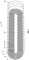
- a multi-overlapped coreless filter element 10 is illustrated and constructed according to an embodiment of the invention.
- the filter element 10 has integrated therein a combination of fibers including carrier fibers having an average size greater than about 3 micron; and on the other hand fine fibers having a size of less than about 800 nanometer (more preferably less than 500 nanometer, even more preferably less than 250 nanometer and most preferably less than 100 nanometer).
- the filter element 10 includes a first multi-overlapped nonwoven fabric strip 12, a second multi-overlapped nonwoven fabric strip 13, a third multi-overlapped nonwoven fabric strip 14, and a fourth multi-overlapped nonwoven fabric strip 15.
- a strip will sometimes be referred to as a sheet and vice versa.
- a partial width strip is provided (partial width relative to the axial length of the filter element), so that each strip can be helically wound in this embodiment.
- Each fabric strip 12-15 is spirally or helically wound in overlapping layers to form overlapping bands 16, 17, 18, 19, respectively. Collectively, these bands form a non-pleated tubular ring 20 of a depth media having a total media thickness T of at least about 1 ⁇ 4 centimeter.
- the radially interior surface of the innermost band 16 forms the periphery of an axially extending annular space (that may be used to collect clean fluid and facilitate axial flow of cleaned fluid).
- This hollow interior space extends from one end of the filter element to the oppositely facing end of the filter element 10.
- the thickness of the fabric (as well as fine fiber layers where illustrated) is exaggerated for purposes of demonstration.
- the tubular ring of depth media typically has at least 1 ⁇ 4 cm in thickness (radial thickness) and more typically between 1 ⁇ 2 cm and 5 cm (more typically between 1 cm and 3 cm) of thickness as a consequence of the wraps.
- each strip 12-15 at least partially overlaps itself once to make the given band thick at a range of generally between 2-8 wraps thick for one of the given fabric strips.
- similar embodiments of the filter element 10 employ at least 1 fabric strip thick and more typically between 2-6 fabric strips.
- filter elements can be made employing the helical wrapping technique of between 2 and 48 strips thick (most typically between 6 and 32 layers thick).
- a preformed multiple laminated layer filter media sheet 100 is selected and employed for use as the innermost fabric strip 13.
- the multiple layer filter media sheet 100 is selected and employed for use as the second innermost fabric strip 14 as well as the innermost fabric strip 13.
- the upstream fabric strips 15, 16 may employ no fine fibers but a more open structure to create a gradient media throughout the entire thickness T.
- the upstream non-woven fabric strips 15, 16 may be composed of selected polymeric fibers such as polyester and polypropylene which serve as both base fibers and binder fibers.
- Base fibers have higher melting points than binder fibers, which is also referred to herein as bi-component media or multi-component media.
- the role of base fibers is to produce small pore structures in the coreless filter element 11.
- the role of the binder fiber or binder material is to bond the base fibers into a rigid filter element that does not require a separate core.
- the binder fibers may consist of a pure fiber or of one having a lower melting point outer shell and a higher melting point inner core. If the binder fiber is of the pure type, then it will liquefy throughout in the presence of sufficient heat.
- the binder fiber has an outer shell and an inner core, then it is subjected to temperatures that liquefy only the outer shell in the presence of heat, leaving the inner core to assist the base fiber in producing small pore structures.
- the role therefore of the binder fiber is to liquefy either in whole or in part in the presence of heat, the liquid fraction thereof to wick onto the base fibers to form a bond point between the base fibers, thereby bonding the base fibers together upon cooling.
- the binder material may be in a form other than fibrous.
- the multiple layer filter media sheet 100 may be employed at different locations upstream or downstream locations and may be selected for use for any one or more of the strips 12-15.
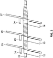
- FIG. 2 of the drawings designates a hollow cylindrical mandrel with an annular exterior surface and an annular interior surface, said annular interior surface forming the periphery of a cylindrical channel 23, through which flows a liquid or gas heat exchange medium (not shown).
- Band 16 of multi-overlapped nonwoven fabric strip 12 is shown overlapped by band 17 of multi-overlapped non-woven fabric strip 13, which in turn is overlapped by band 18 of multi-overlapped nonwoven fabric strip 14, which is then overlapped by band 19 of multi-overlapped nonwoven fabric strip 15.
- FIG. 3 of the drawings only three stages are shown of the multistage winding machine shown in greater detail in the aforementioned referenced patents.
- a first compression belt 25 is shown wrapping, in a multi-overlapped fashion, the first nonwoven fabric strip 12 about the hollow mandrel 22.
- a second compression belt 26 is shown wrapping, in a multi-overlapped fashion, the second nonwoven fabric strip 13 about multi-overlapped nonwoven fabric strip 12.
- a third compression belt 27 is shown wrapping, in a multi-overlapped fashion, the third non-woven fabric strip 14 about multi-overlapped nonwoven fabric strip 13.
- a first heater array of preferably infrared heaters 28 is shown in a position to apply heat, simultaneously with the compression of compression belt 25, to multi-overlapped nonwoven fabric strip 12.
- a second heater array of infrared heaters 29 is shown in a position to apply heat, simultaneously with the compression of compression belt 26, to multi-overlapped nonwoven fabric strip 13.
- a third heater array of infrared heaters 30 is shown in a position to apply heat, simultaneously with the compression of compression belt 27, to multi-overlapped nonwoven fabric strip 14.
- the filter element 10 is formed into a tubular ring of depth media 20, from there it may be cut into axial length segments and then configured with opposed open and closed end caps 32, 34 sealingly bonded to opposed ends of the tubular ring as shown in FIG. 1A .
- the open end cap 32 has an opening 35 to serve as an outlet port for cleaned fluid.
- One or more seals such as O-ring gaskets 36 may be disposed on the end cap 32 for sealing with a mounting head of a fluid system.
- a perforated core 38 may be employed along the inside of the media.
- multi-layer filter sheet 100 provides flow structure within the individual strip 12 that employs the filter sheet 100.
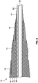
- the strips are canted relative to the longitudinal axis 40 of the filter element 10.
- the individual fine fiber layers 42 e.g. corresponding to 124, 126, 128, 130, 132, 134, 136, 138, 140, 142 in FIG.
- the more open and porous substrate 44 are also arranged at a canted alignment and non-parallel to the axis 40; and thereby may act as a drainage layer or fluid flow layer within the strip 12.
- the present arrangement may eventually decrease in efficiency over time as particulate loading causes more flow along the canted flow paths through the substrate layers 44 as opposed to radially through the media (and fine fiber layers 42).
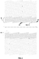
- FIG. 5-6 a filter element 50 yet another embodiment is schematically illustrated in cross section.
- the filter element 50 is a similarly helically wrapped filter element to the first embodiment and as such similar reference numbers are used, but additionally employs an interlay strip 52 that overlays the strip 12 employing the multi-layer filter sheet 100 (see FIG. 9 ) with fine fiber layers 42.
- the arrangement and variations of an interlay may also be in accordance with any of the examples of U.S. Patent Publication No. 2008/0128364 to Cloud et al . While a single band in this embodiment is shown to have an interlay, multiple bands 16-19 (such as in first embodiment shown in FIG. 1 ) may employ an interlay. One or more of these bands may include at least one of the strips as having fine fibers (the interlay may also optionally include fine fibers).
- a lower efficiency interlay strip 52 is wrapped along with the strip 12 employing the multi-layer filter sheet 100.
- one of the strips will have a greater flow porosity and the other strip a greater efficiency and less porous structure resulting in greater flow horizontally/diagonally.
- more flow in this embodiment may be along the canted path through the interlay strip 52 as compared with the efficiency strip 12 employing the multi-layer filter sheet 100.
- FIG. 7 another embodiment of a filter element 60 is illustrated employing a spiral wrap employing at least one full length sheet that is spirally wrapped about the axis and in this embodiment two sheets 62, 64 (more sheets may also be co-wrapped). At least one of the sheets and in this case sheet 62 has fine fibers integrated therein (e.g. sheet 62 may be formed from sheet 100 of FIG. 9 ). Also illustrated, is that the other sheet 64 may not have any fine fibers, but may serve as a spacer layer. Each of the sheets extends parallel to the filter axis 66, unlike the previous embodiments.
- fluid may be able to flow along a spiral path, but more typically (especially if many wraps are employed) fluid is forced to travel radially inward through the filter medias of the strips 62, 64. In either event, this forms a depth media as multiple layers are employed. Further, a lower efficiency strip may have more wraps and be longer such as to continue to spirally wrap around the element even after the higher efficiency sheet 62 terminates.
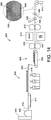
- FIGS 8-8A yet another embodiment is schematically illustrated showing the creation of a depth media element 70 employing fine fibers.
- multiple stations of melt blown heads 72 and electro-spinning modules are arranged.
- the melt blown heads 72 pump melted polymer through a die having orifices and are blown at a given speed and distance to create fibers having a selected diameter.
- Melt blown heads often will produce fibers of greater than 1 micron, but may also create fine fibers under 1 micron and down to about 600-700 nanometer if subject to electrical fields. As such, fine fibers as well as coarse may be created by melt blowing, which may be used in any of the embodiments herein.
- fine fibers in an embodiment are characterized as being at least 4 times as small as the melt blown fibers.
- Each of the melt blow and electrospinning module stations 72a-c and 74A-c may produce different sizes of fibers as may be desired.
- melt blown fibers and electrospun fibers are thus meant to be more specific terms than fine fibers, which is intended to be generic.
- a perforated core 76 is moved along a shaft 78 rotationally and axially to deposit layers of melt blown fibers 80a-c and electro-spun fibers 82a-c on the core 76.
- electrostatic pinning bars 84 are employed to maintain a charge and differential.
- Electrospinning equipment such the endless chains as disclosed U.S. Provisional Application No. 60/989,218 entitled "Filtration Medias, Fine Fibers Under 100 Nanometers, and Methods" may be employed but with the endless strand extending under and parallel to the support shaft 78 for the process. From this process, a filter element is created having successive layers of melt blown fibers 80a-80c and electrospun fibers 82a-82c as illustrated in FIG. 8A .
- the multilayer filter sheet 100 employing multiple layers of fine fibers as used in many of the previous embodiments is illustrated along with alternative ways to make such a multi-layer sheet. It should be appreciated, that embodiments that use strips of the sheet 100 may have fewer (or more) layers of fine fibers deposited thereon. In some embodiments some strips (such as for FIG. 1 ), may have a single layer of fine fiber, while in others and more preferably, multiple fine fiber layers are deposited and contained within a strip. In either case, it may be referred to as a "composite media".
- a plurality of scrim layers and a plurality of fine fiber layers of fine fibers are laminated together a single filter media sheet, with selected fine fiber layers being spaced apart and separated within the first filter media sheet by the scrim.
- the fine fibers will be protected and sandwiched between a layers of substrate of carrier fibers.
- the term “substrate” is meant to be broad in nature and meant to include any structure upon which fine fibers are carried or deposited.
- “Substrate” may include conventional formed filter medias such as scrims and the like that may be unwound from media rolls.
- Such filter medias have a fiber entanglement that typically bonded or secured together mechanically, chemically, adhesively and/or otherwise and thereby have strength such that they cannot be easily torn manually (e.g. a 1 square foot sheet typically holds up to application of tension of 5 lbs force) and have filtrations properties.
- Substrate may also include looser fiber entanglements that may not be bonded together or secured together (e.g. a 1 square foot sheet may fall apart upon application of tension of 5 lbs force).
- a "scrim” used as herein refers to woven or non-woven fiber entanglement, wherein the fibers are bonded and compressed into a planar formed media.
- nanofiber coverage can be characterized.
- a first way to characterize nanofiber coverage is basis weight.
- basis weight is dependent in part upon the specific gravity of the material of the nanofiber, as well as the selected size (e.g. also interchangeably referred to as fiber diameter and/or thickness) of the nanofiber.
- Another useful measure for characterizing nanofiber coverage is calculated lineal distance of nanofiber coverage that can be expressed in terms of kilometer per square meter (km/m2), which is useful as this measure of coverage eliminate variability due to diameter of the fine fiber and variability due to specific gravity differences among different materials that may be employed.
- fine fibers having an average fiber diameter of 0.08 micron (80 nanometer) were employed.
- a double sized fiber e.g. a 160 nanometer sized fine fiber
- ⁇ *R2 simple area calculation
- An overapplication of fine fibers can lead to a plastic film that is not very pervious or porous, thus not suitable for a filter media.
- Using smaller fine fibers is desirable as a higher linear coverage level can be obtained.
- basis weight may increase 2-2.5 times for a doubling in fiber diameter (about 4-6 times for a quadrupling of fiber diameter); and for purposes of ease a doubling will be employed.
- Embodiments herein are useable for a range of fine fibers less than 1 micron, typically less than 500 nm, and more preferably smaller fibers under 150 nm. However, coverage adjustments can be made according to principles above to embodiments herein.
- first, second or third in reference to a filter media composite or layers is not meant to refer to a specific location.
- First layer is not intended to mean the very first layer, nor meant to be indicative of upstream or downstream location relative to another layer (“upstream” or “downstream”) can be used for that purpose. Instead, such terms as “first” and “second” are used for antecedent basis purposes.
- FIG. 9 is a schematic cross-sectional view of a filter media 100 according to an embodiment of the present invention. It is schematic in the sense that in reality the fine fiber layer has virtually no thickness, but for illustration and understanding, thickness is illustrated in FIG. 9 and other schematic illustrations.
- the filter media 100 includes at least two different fibers, for example, electrospun nanofibers and a substrate of coarser fibers carrying the nanofibers. As such, the filter media 100 is also referred to as a composite filter media, a composite media, or other like terms in this application.
- the filter media 100 is particularly well suited for liquid particulate filtration applications with examples/embodiments having a significant particulate filtration impact now to liquid applications, the filter media 100 may be used in other fluid filtration applications.
- the filter media 100 comprises 10 layers of substrate 102, 104, 106, 108, 110, 112, 114, 116, 118, 120, each of which carrying fine fibers 124, 126, 128, 130, 132, 134, 136, 138, 140, 142, and a media 122 on top of the fine fibers 142.
- the substrate, 102, 104, 106, 108, 110, 112, 114, 116, 118, 120 and the media 122 are formed of fibers having an average fiber diameter typically larger than that of the fine fibers.
- the substrate layers 102, 104, 106, 108, 110, 112, 114, 116, 118, 120, the fine fibers 124, 126, 128, 130, 132, 134, 136, 138, 140, 142, and the media 122 are laminated and tightly compressed together to increase fiber surface area per volume.
- this embodiment is shown with the media layer 122, this media layer is optional, and thus, the filter media 100 according to other embodiments may not include this media layer 122.
- FIG. 10 illustrates the filter media 100 in a pre-compressed state 144 and a compressed state 146.
- the filter media 100 in the pre-compressed state 144 has an initial thickness t' (also referred herein as an original thickness.)
- the filter media 100 in the pre-compressed state 144 is compressed into the compressed state 146 using a set of rollers 148, 150, wherein the initial thickness t' is reduced to a final thickness t.
- the filter media 100 in the pre-compressed state 144 is heated before compressing.
- fibers of the substrate relax and reorient to increase an average distance between the fibers during heating (such as a scrim that has been at least partially compressed during the scrim production process.)
- the substrate layers expand and loft, wherein the thickness of each of the substrate layer increases.
- the fine fibers which are carried by these fibers move and reorient with the fibers.
- fine fibers are extended, pushed and pulled with the larger fibers. It is believed this may created a 3-dimensional matrix for fine fibers as opposed to being merely flat or planar (such 3-dimensional matrix of fine fibers can still be considered to be and may be referred herein as a "layer" even if integrated into surface of substrate.)
- the initial thickness t' of the pre-compressed state 144 can increase by at least 1.5 times, 2 times, 3 times or even more via heating.
- the final thickness t of the filter media 100 after subsequent compression of the lofted filter media 100 can be either less than, or equal to, or greater than the initial thickness t', depending on the amount of expansion during heating and the amount of reduction during compression.
- the filter media 100 in the pre-compressed state 144 can be heated and compressed simultaneously via a set of heated calendering rollers. In such embodiments, there may not be any expansion or a very slight increase in the initial thickness t' prior to the thickness reduction to the final thickness t.
- the compressed filter media 100 having the final thickness t can be heated post compression, wherein the thickness t may be increased.
- the filter media 100 can be heated more than once.
- the filter media 100 can be compressed by a set of rollers arranged in an oven, such that the filter media 100 is heated immediately before being compressed, while being compressed, and immediately after being compressed.
- processing of the media after deposition of the fine fibers to rearrange fine fibers into more of a 3-dimensional matrix is advantageous. Expansion and/or compression are examples of such processing. Such processing can afford a greater porosity and may be used for better flow and/or to facilitate heavier coverage of fine fiber deposition.
- the final thickness t can be between about 50% and 300% of the initial thickness t', preferably between about 70% and 200% of the initial thickness t', and more preferably between 80% and 150% of the initial thickness t'.
- the fine fibers 124, 126, 128, 130, 132, 134, 136, 138, 140, 142 become more integrated with the coarse fibers of the adjacent substrate layers 102, 104, 106, 108, 110, 112, 114, 116, 118, 120 and form 3 dimensional fine fiber matrix within the filter media 100.
- the filter media 100 in this embodiment includes 10 layers of substrate carrying fine fibers, other embodiments can include more or less substrate layers carrying fine fibers.
- a filter media can include a single substrate layer carrying a sufficiently heavy coverage of fine fibers (e.g. at least about 0.3g/m 2 .)
- the substrate layers 102, 104, 106, 108, 110, 112, 114, 116, 118, 120 can be formed of any suitable porous material.
- Each of the substrate layer can be formed of a same type of porous material or different types of porous material.
- each layer of the substrate 102, 104, 106, 108, 110, 112, 114, 116, 118, 120 comprises a formed filter media.
- the formed filter media comprises fibers that are bonded together.
- the fibers of the formed filter media may be bonded together by solvent bonding, thermal bonding, and/or pressure bonding.
- the formed filter media can carry fine fibers and provide a structural support.
- the formed filter media is also referred to as a substrate filter media, a filter media substrate, a substrate, a filter media, or other like terms in the present application.
- the substrate may comprise one or more webs of fibers which are loosely tangled together in a highly fluffed thick state and may not be bonded together as in the case of a formed filter media.
- the web of coarse fibers can easily be pulled apart with very little manual effort and has little structural integrity such that it is not considered a formed filter media in the conventional sense.
- the fibers of the web of fibers typically have a larger average fiber diameter than an average fiber diameter of the fine fibers.
- the web of fibers is also referred to as a web of coarse fibers or other like terms in this application.
- a composite filter media including fine fibers integrated with such web of coarse fibers is described in Integrated Nanofiber Filter Media, US Patent Application Publication No. 2009/0266759 , which is assigned to the assignee of the present application.
- the substrate is formed of a multi-component filter media.
- multi-component filter media can comprise fibers formed of a first material and fibers formed of a second material, wherein the first material and the second material are different materials.
- a multi-component filter media can be formed of fibers including at least two different materials, such as fibers including a core formed of the first material and a sheath formed of the second material, as described in detail below.
- a multi-component filter media including two different materials is refer to herein as "bi-component filter media", “bi-component media”, and like terms.
- each of the substrate layers 102, 104, 106, 108, 110, 112, 114, 116, 118, 120 comprises a scrim formed of bi-component fibers including two different materials having different melting points.
- a composite filter media comprising fine fibers and a substrate formed of such multi-component fibers are described in Multi-Component Filter Media with Nanofiber Attachment, PCT Patent Application No. PCT/US09/50392 , which is assigned to the assignee of the present application.
- one component of the bi-component fibers of the scrim has a lower melting point than the other component.
- the low melt component can be any suitable polymer such as polypropylene, polyethylene, or polyester.
- the other component may be a polymer having a higher melting point than the low melt component, or other suitable fiber materials such as glass and/or cellulose.
- the bi-component fibers are bonded together and/or compressed together to form a scrim or a substrate filter media having a certain thickness.
- the bi-component fibers of the scrim used as the substrate 102, 104, 106, 108, 110, 112, 114, 116, 118, 120 can include a high melt polymer component and a low melt polymer component.
- the bi-component may comprise a high-melt polyester and a low-melt polyester, in which one has a higher melting temperature than the other.
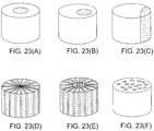
- FIGS. 23(A)-(H) schematically illustrate bi-component fibers according to various embodiments.
- FIG. 23(A) shows a concentric sheath/core type bi-component, wherein a core is formed of a high melt polymeric component and a sheath is formed of a low melt polymeric component.
- the high melt polymer component is formed of a polymer having a higher melting temperature than the low melt polymer component.
- Suitable high melt polymers include, but are not limited to, polyester and polyamide.
- Suitable low melt polymers include polypropylene, polyethylene, co-polyester, or any other suitable polymers having a lower melting temperature than the selected high melt polymer.
- bi-component fibers may be formed of a polyester core and a polypropylene sheath. In this embodiment, the bi-component fibers are formed of two different types of polyesters, one having a higher melting point than the other.
- the fibers of the substrates are formed to have a larger average fiber diameter than that of the fine fibers.
- the fibers of the substrates have an average fiber diameter that is at least 4 times as that of the fine fibers.
- the fibers of the substrates can have an average fiber diameter of greater than about 0.6 micron, preferably greater than about 3 micron, and more preferably, greater than 5 micron.
- an average diameter of the bi-component fibers of the substrate are between about 1 micron and about 40 micron, and more typically between about 10-40 microns.
- the coarse fibers are compressed and/or heated, for example via a set of calendering rollers and/or an oven, to form the substrate 102, 104, 106, 108, 110, 112, 114, 116, 118, 120, wherein any of the substrate layers has a thickness between about 0.05 and 1.0 mm, preferably between about 0.1 and 0.5 mm.
- Such substrate can provide a structural support necessary for the fine fibers.
- Bi-component scrims of various thicknesses suitable for use as any of the substrate layers are commercially available through various suppliers, such as HDK Industries, Inc. of Rogersville, TN, or other filter media suppliers. Thus, the substrate can be selected from such off the shelf bi-component medias.
- each layer of the substrate 102, 104, 106, 108, 110, 112, 114, 116, 118, 120 and the media 122 comprise a scrim formed of bi-component staple fibers having a high melt polyester core and a low melt polyester sheath.
- the bi-component staple fibers are compressed together to form the scrim, wherein the bi-component staple fibers are bonded together chemically, mechanically and/or thermally.
- the bi-component staple fibers are heated to or near the melting temperature of the low melt polyester and compressed together, wherein the sheath formed of the low melt polyester melts or softens and acts as a bonding agent to bond fibers together.
- the fine fibers 124, 126, 128, 130, 132, 134, 136, 138, 140, 142 can be deposited directly on the corresponding substrate 102, 104, 106, 108, 110, 112, 114, 116, 118, 120 as they are formed.
- the fine fibers may be separately prepared as a web of fine fibers, then laminated with the substrate.
- the fine fibers may comprise fibers having various fiber diameters, preferably, the fine are nanofibers having very fine fiber diameter.
- Such fine fibers can be formed by electrospinning or other suitable processes.
- the fine fibers are electrospun nanofibers having an average fiber diameter less than about 1 micron, preferably less than 0.5 micron, and more preferably between 0.01 and 0.3 microns. Examples herein have employed a smaller average diameter of 0.08 micron (80nm). Such small diameter fine fibers can afford the ability to pack more fibers together in a given volume to provide an increased fiber surface area, which can increase filtration efficiency while decreasing pressure drop of a filter media.
- the fine fibers may be formed by various suitable polymeric materials.
- the fine fibers are typically formed of a material having a higher melt temperature than at least the low-melt component of the bi-component fibers of the substrate.
- the fine fibers are formed of a polyamide.
- polyvinyl chloride PVC
- polyolefin polyacetal
- polyester cellulous ether
- polyalkylene sulfide polyarylene oxide
- polysulfone modified polysulfone polymers
- polyvinyl alcohol polyamide
- polystyrene polyacrylonitrile
- polyvinylidene chloride polymethyl methacrylate
- polyvinylidene fluoride PVC
- Solvents for making polymeric solution for electrostatic spinning may include acetic acid, formic acid, m-cresol, tri-fluoro ethanol, hexafluoro isopropanol chlorinated solvents, alcohols, water, ethanol, isopropanol, acetone, and N-methyl pyrrolidone, and methanol.
- the fine fibers are formed of nylon-6 (polyamide-6, also referred to as "PA-6" herein) via electrospinning, wherein the electrospun fine fibers are deposited directly on the substrate.
- the fine fibers 124 are generated electrostatically from a solution containing nylon-6 and deposited on a surface of the substrate 102.
- the fine fibers 126 can be similarly generated and deposited on the substrate layer 104, and so on.
- the substrate layers 102, 104, 106, 108, 110, 112, 114, 116, 118, 120 coated with the electrospun nanofibers 124, 126, 128, 130, 132, 134, 136, 138, 140, 142 are then laminated together with the media 122, such that each layer of the fine fibers is sandwiched between the adjacent substrate and/or the media 122 to create the filter media 100 in the pre-compressed state 144 as shown in FIG. 10 .
- the filter media 100 in the pre-compressed state 144 is then compressed to form the filter media 100 in its final compressed state 146 as shown in FIGS. 1 and 2 .
- the filter media 100 is heated before, during, and/or after the compression.
- the filter media 100 in the pre-compressed state 144 is heated prior to passing through the set of rollers 148, 150. Further, the set of rollers 148, 150 can be heated to further heat the filter media 100 during the compression.
- the bonding between the fine fibers and adjacent coarser fibers of the substrates and/or media 122 may involve solvent bonding, pressure bonding, and/or thermal bonding.
- the solvent remaining on the surface of the fine fibers can effectuate a solvent bonding as the fiber fibers come in contact with the coarse fibers of the substrate.
- the low melt component of the bi-component fibers of the substrate can be used to enhance bonding between the fine fibers and the adjacent coarse fibers of the substrate.
- the filter media 100 is heated to or near the melting point of the low melt component and compressed, wherein the low melt component of the bi-component coarse fibers melts or softens, which allows the adjacent fine fibers to embed into the low melt component as they are compressed together, thereby enhancing the bonding between the coarse fibers and the fine fibers (via pressure bonding and thermal bonding.)
- the adhesion between the fine fibers and the substrate on which the fine fibers were deposited are greater than that of between the fine fibers and the other adjacent substrate.
- the adhesion between the fine fibers 124 and the substrate 102 is greater than the adhesion between the fine fibers 124 and the substrate 104.
- the filter media 100 of such embodiment can be separated into ten layers of substrates carrying fine fibers (102/124, 104/126, 106/128, 108/130, 110/132, 112/134, 114/136, 116/138, 118/140, 120/142) and the media 122.
- each of the substrate layers is formed of a bi-component fiber scrim having an average fiber diameter between about 1 and 40 microns and a basis weight between about 16,95 and 508,85 g/m 2 (0.5 and 15 oz/yd 2 ).
- the bi-component fibers comprise a high-melt polyester core and a low melt polyester sheath.
- the fine are electrospun nanofibers formed of nylon-6.
- the fine fibers have an average fiber diameter between about 0.01 and 0.5 microns, wherein each layer of the fine fibers 124, 126, 128, 130, 132, 134, 136, 138, 140, 142 has a basis weight between about 0.03 g/m 2 and 0.5 g/m 2 , providing total fine fiber basis coverage between 0.3 g/m 2 and 5 g/m 2 .
- the fine fiber coverage of the filter media 100 for liquid particulate filtration applications is significantly greater that the fine fiber coverage of gas or air filtration medias.
- a target basis weight of fine fibers on each substrate layer is selected according to an average diameter of the fine fibers and a desired efficiency and capacity of the filter media.
- a desired efficiency and capacity of the filter media 100 can be obtained by adjusting fine fiber diameter, fine fiber coverage on each substrate, number of fine fiber layers, amount of lofting and compression.
- the fine fiber coverage can be characterized in terms of a basis weight
- the basis weight depends upon a specific weight of a polymer(s) and a diameter of the fine fibers.
- the linear coverage truly measures how much fiber is laid down as the quantity of fiber.
- preferred fine fiber linear coverage ranges are greater than 5,000 km/ m 2 for the heaviest coverage fine fibers, more preferably greater than 10,000 km/ m 2 , and most preferably between 20,000 km/ m 2 and 60,000 km/ m 2 .
- the fine fiber coverages in various terms including the basis weight and linear coverage for fine fibers having an average fiber diameter of about 0.08 micron (80 nm) according to embodiments of the present invention are shown below in Table 1.
- the fine fibers of these embodiments are formed of PA-6 having a density of 1.084 g/cm 3 via a electrospinning process. As shown, Table 1 includes fine fiber mass coverage form 0.03 - 0.225 g/m 2 .
- fine fiber coverage may vary based on fiber diameter, based on examples using 80 nm fibers and other calculations, typically embodiments that employ fine fibers having less than 500 nm average diameter will have similar coverage ranges for purpose of broad characterization and claiming purposes.
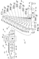
- FIG. 11 schematically illustrates a representative process of making a filter media according to a processing embodiment of the present invention.
- this embodiment includes process steps for making the filter media 100 of FIG. 9 , the process can produce filter medias according to other embodiments of the present invention with minor modifications.
- a system 200 shown in FIG. 11 includes an upstream system 201 for making a composite media including a substrate and fine fibers deposited thereon, and a downstream system 203 for laminating, lofting and compressing multiple layers of composite media to make a multilayer composite filter media for liquid particulate filtration applications.
- the upstream system 201 includes an unwinding station 202, an electrospinning station 204, an optional oven 206, an optional set of rollers 207 and a rewinding station 208.
- a roll of scrim 210 which is used here as a substrate layer, is unwound from the unwinding station 202.
- the scrim 212 unwound from the roll of scrim 210 travels in a machine direction 214 toward the electrospinning station 204.
- fine fibers 216 are formed and deposited on one surface of the scrim 212 to form a composite media 218 comprising the scrim carrying the fine fibers 216.
- the composite media 218 may be heated and compressed in the optional oven 206 and the optional set of rollers 207 before being wound into a roll of composite media 230 on the rewound station 208 for improved adhesion between the fine fibers and the substrate.
- the scrim may be formed in an upstream process of the system 200 (either part of a continuous line process or interrupted line process) or may be purchased in a roll form from a supplier such as HDK or other suitable media supplier such as H&V or Ahlstrom or the like.
- the scrim can be formed of various suitable materials, such as bi-component fibers of FIGS. 3-10 as discussed above.
- the scrim can be formed of high melt polyester core/low melt polyester sheath bi-component staple fibers, which are compressed and/or heated to form the roll of scrim 210 having a desired thickness and solidity.
- the substrate layer may be other single component media that may be compressed and held in place via a solvent bond, heat bond or the like.
- the concentric sheath/core type bi-component fibers may be coextruded using a high melt polyester as the core and a low melt polyester as the sheath. Such bi-component fibers can then be used to form a scrim or a filter media.
- the bi-component fibers are used as staple fibers to form a multi-component filter media or a scrim via conventional dry laying or air laying process.
- the staple fibers used in this process are relatively short and discontinuous but long enough to be handled by conventional equipment.
- Bales of the bi-component fibers can be fed through a chute feed and separated into individual fibers in a carding device, which are then air laid into a web of fibers (which itself for purposes of the present disclosure may be used as a substrate.)
- the web of fibers is then compressed using a set of calendering rollers to form the roll of scrim 210 (which can also be used as a substrate.)
- the web of the fibers may optionally be heated before entering the set of calendering rollers.
- the scrim 210 of this embodiment comprises bi-component fibers, including a high melt component and a low melt component, it is also referred to as a bi-component filter media.
- the web of fibers are folded before being calendered to form a thicker bi-component filter media.
- a web comprising high melt polymer fibers such as polyester fibers and a web comprising low melt polymer fibers such as polypropylene fibers can be formed, separated and laminated together to form the roll of bi-component filter media or scrim.
- the fine fibers 216 are deposited on the low melt side of the scrim 212.
- the low melt web is substantially thinner than the high melt web, such that the low melt component does not clog the surface of the high melt web when heated and melted.
- the bi-component fiber scrim can be formed via a melt blowing process.
- molten polyester and molten polypropylene can be extruded and drawn with heated, high velocity air to form coarse fibers.
- the fibers can be collected as a web on a moving screen to form a bi-component scrim 210.
- the multi-component fiber filter media or scrim may also be spun-bounded using at least two different polymeric materials.
- a molten polymeric material passes through a plurality of extrusion orifices to form a multifilamentary spinline.
- the multifilamentary spinline is drawn in order to increase its tenacity and passed through a quench zone wherein solidification occurs which is collected on a support such as a moving screen.
- the spun-bounding process is similar to the melt blowing process, but melt blown fibers are usually finer than spun-bounded fibers.
- the multi-component filter media is wet-laid.
- high melt fibers and low melt fibers are dispersed on a conveying belt, and the fibers are spread in a uniform web while still wet.
- Wet-laid operations typically use 6,35 mm to 19,05 mm (1 ⁇ 4" to 3 ⁇ 4") long fibers, but sometimes longer if the fiber is stiff or thick.
- the above discussed fibers, according to various embodiments, are compressed to form a scrim 210 or a filter media having a desired thickness.
- the scrim 212 enters the electrospinning station 204, wherein the fine fibers 216 are formed and deposited on one surface of the scrim 212.
- the fine fibers 216 are electrospun from electrospinning cells 222 and deposited on the web of scrim 212.
- the electrospinning process of the system 200 can be substantially similar to the electrospinning process disclosed in Fine Fibers Under 100 Nanometers, And Methods, U.S. Patent Application Publication No. U.S. 2009/0199717 , assigned to the assignee of the present application.
- nozzle banks or other electrospinning equipment can be utilized to form the fine fibers.
- Such alternative electrospinning devices or rerouting of chain electrodes of the cells 222 can permit the fibers to be deposited in any orientation desired (e.g. upwardly is shown although fibers can also be spun downwardly, horizontally or diagonally onto a conveyor carrying coarser fibers).
- the electrospinning process produces synthetic fibers of small diameter, which are also known as nanofibers.
- the basic process of electrostatic spinning involves the introduction or electrostatic charge to a stream of polymer melt or solution in the presence of a strong electric field, such as a high voltage gradient.
- Introduction of electrostatic charge to polymeric fluid in the electrospinning cells 222 results in formation of a jet of charged fluid.
- the charged jet accelerates and thins in the electrostatic field, attracted toward a ground collector.
- viscoelastic forces of polymeric fluids stabilize the jet, forming small diameter filaments.
- An average diameter of fibers may be controlled by the design of eletrospinning cells 222 and formulation of polymeric solutions.
- the polymeric solutions used to form the fine fibers can comprise various polymeric materials and solvents.
- polymeric materials include polyvinyl chloride (PVC), polyolefin, polyacetal, polyester, cellulous ether, polyalkylene sulfide, polyarylene oxide, polysulfone, modified polysulfone polymers and polyvinyl alcohol, polyamide, polystyrene, polyacrylonitrile, polyvinylidene chloride, polymethyl methacrylate, polyvinylidene fluoride.
- Solvents for making polymeric solution for electrostatic spinning may include acetic acid, formic acid, m-cresol, tri-fluoro ethanol, hexafluoro isopropanol chlorinated solvents, alcohols, water, ethanol, isopropanol, acetone, and N-methyl pyrrolidone, and methanol.
- the solvent and the polymer can be matched for appropriated use based on sufficient solubility of the polymer in a given solvent and/or solvent mixture (both of which may be referred to as "solvent".)
- formic acid may be chosen for nylon-6. Reference can be had to the aforementioned patents for further details on electrospinning of fine fibers.
- an electrostatic field is generated between electrodes in the electrospinning cells 222 and a vacuum collector conveyor 224, provided by a high voltage supply generating a high voltage differential.
- a vacuum collector conveyor 224 provides a high voltage supply generating a high voltage differential.
- the fine fibers 216 formed at the electrodes of the electrospinning cells 222 are drawn toward the vacuum collector conveyor 224 by the force provided by the electrostatic field.
- the vacuum collector conveyor 224 also holds and transfers the scrim 212 in the machine direction 214. As configured, the scrim 212 is positioned between the electrospinning cells 222 and the vacuum collector conveyor 224, such that the fine fibers 216 are deposited on the scrim 212.
- the multi-component scrim 212 is positioned between the electrospinning cells 222 and the vacuum collector conveyor 224, such that the low melt component surface of the multi-component scrim faces the electrospinning cells 222.
- the electrospinning cells 222 contain a polymeric solution comprising polyamide-6 (PA-6) and a suitable solvent consisting of 2/3 acetic acid and 1/3 formic acid. In such a solvent, both acetic acid and formic acid act as a dissolving agent to dissolve PA-6, and acetic acid controls conductivity and surface tension of the polymeric solution.
- the electrospinning cells 222 generate fine fibers formed of PA-6, which are deposited onto a surface of the scrim 212. As the fine fibers 216 are deposited on the surface of the scrim 212, some fine fibers 216 entangle with coarse fibers of the scrim proximate the surface facing the electrospinning cells 222. When some fine fibers 216 entangle with some coarse fibers, solvent remaining in the fine fibers 216 from the electrospinning process can effectuate a solvent bonding between the fine fibers 216 and the coarse fibers of the scrim 212.
- PA-6 polyamide-6
- suitable solvent consisting of 2/3 acetic
- the fine fibers can be formed by other suitable processes such as a melt blowing process.
- the fine fibers having an average fiber diameter of about 0.6 - 0.7 micron can be formed via a melt blowing under an influence electrical fields.
- the coarse fibers for a substrate are prepared to have an average fiber diameter at least 4 times larger than the fine fibers.
- melt blown fibers and electrospun nanofibers are thus meant to be more specific terms than fine fibers, which is intended to be generic.
- the bonding between bi-component fibers of the scrim 212 and the fine fibers 216 may be enhanced via thermal bonding and pressure bonding by the optional oven 206 and the optional set of calendering rollers 207.
- the composite media 218 As the composite media 218 is heated in the oven 206, the low melt polymer component of the bi-component fibers softens or melts and allowing the fine fibers 216 to embed into the low melt polymer component.
- the composite filter media 218 is heated to at least above the glass transition temperature of the low melt component, and more preferably to or near the melting temperature of the low melt component.
- the composite media 218 is heated to or near the melt point of low melt polyester, such that the outer low melt polyester layer of the bi-component fibers melts and bonds with the fine fibers 216 formed of PA-6.
- PA-6 fine fibers 216 and the high melt polyester core of the bi-component fibers do not melt, since PA-6 and the high melt polyester have a significantly higher melting temperature than that of the low melt polyester.
- the low melt polyester, which has the lowest melting temperature, melts or softens, and adjacent PA-6 fine fibers 216 are embedded in the softened or melted low melt polyester, thereby bonding the fine fibers 216 and the scrim 212 together.
- the low melt polyester acts as a bonding agent between the bi-component fiber scrim 212 and the fine fibers 216.
- the bonding between the fine fibers 216 and the scrim 212 can further be enhanced through pressure bonding via the set of rollers 207.
- the fine fibers 216 and the scrim 212 are compressed together, wherein the fine fibers are further embedded into the fibers of the scrim 212. Further, the compression reduces voids in the composite media to form a composite media 220 with an increased solidity.
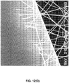
- FIGS. 12(A)-12(D) are Scanning Electron Microscopic (SEM) images of the bi-component fibers of the scrim 212 and the fine fibers 216 proximate the surface of the scrim 212 taken at various magnification levels. As shown in the SEM images taken at magnification levels x300 and x1000 of FIGS. 12(A) and 12(B) , the fine fibers 216 deposited on the web of scrim 212 form a spider web like fiber structure between the coarser bi-component fibers that are located proximate the surface of the scrim 212. The SEM images taken at higher magnifications ( FIG. 12(C) at x2,000 and FIG.
- SEM Scanning Electron Microscopic
- the roll of composite media 230 including the bi-component scrim 212 and the fine fibers 216 is laminated with other composite medias 232, 234, 236, 238, 240, 242, 244, 246, 248, and a media 250 in the downstream system 203.
- Each of the composite media rolls 230, 232, 234, 236, 238, 240, 242, 244, 246, 248, and a roll of the media 250 are unwound from unwind stations 252, 254, 256, 258, 260, 262, 264, 266, 268, 270, 272, and laminated together by a set of rollers 274.
- the set of rollers may be a calendering rollers to apply a significant pressure to laminate and significantly reduce a thickness of the layers of composite medias.
- the set of rollers 274 may apply a small pressure to laminate and reduce the thickness of the laminated layers just enough to fit through an oven 276.
- the laminated layers 280 is heated in the oven 276 and compressed via a set of calendering rollers 282, wherein the laminated layers 280 is compressed together into a compressed state having a desired thickness and solidity.
- each roll of the composite media 232, 234, 236, 238, 240, 242, 244, 246, 248 is prepared similarly as the roll of the composite media 230. Therefore, each of the roll of the composite media 232, 234, 236, 238, 240, 242, 244, 246, 248 includes a substrate formed of a bi-component fiber scrim 284, 286, 288, 290, 292, 294, 296, 298, 300, and electrospun nanofibers 302, 304, 306, 308, 310, 312, 314, 316, 318, carried by the bi-component fiber scrim 284, 286, 288, 290, 292, 294, 296, 298, 300.
- each of the substrates 212, 284, 286, 288, 290, 292, 294, 296, 298, 300 and the media 250 are formed of a same bi-component fiber scrim having a thickness between about 0.05 mm and 1.0 mm.
- Each layer of the fine fibers 216, 302, 304, 306, 308, 310, 312, 314, 316, 318, is formed by electrospinning PA-6 polymer solution to produce a fine fiber coverage between about 0.03 g/m 2 and 0.5 g/m 2 .
- the substrates may be formed of different types of filter media or scrim, and each of the fine fibers layer may have different fine fiber coverage.
- the composite media 280 is heated in the oven 276 to or near a melting temperature of the low melt polyester component of the bi-component fiber scrim. During heating the substrates can relax and expand in thicknesses. Thus, the lofted composite media 281 can have a thickness that is at least 1.5 times, 2 times, 3 times or even greater than the thickness of the composite media 280 before being heated in the oven 276. The lofted composite media 281 is then compressed via the set of calendering rollers 282 into the compressed state 320.
- the composite media is compressed, such that the thickness of the composite media 280 is reduced between about 50% and 300%, preferably between about 70% and 200%, and more preferably between about 80% and 150% of the original thickness of the composite media 280 prior to heating ((total thickness of 10 scrim layers carrying 10 fine fiber layers + thickness of media - thickness of the composite media in the compressed state 320)/(total thickness of 10 scrim layers carrying 10 fine fiber layers + thickness of media).)
- the thickness reduction can depend on the amount of lofting during heating. Thus, when the lofting from heating is large, the final thickness of the composite media after compression may be greater than the initial thickness of the composite media before heating.
- the composite media in the compressed state 320 is then wound into a roll of filter media 324.
- the rolls of the composite media 230, 232, 234, 236, 238, 240, 242, 244, 246, 248. and the media 250 are laminated together, such that each of the fine fiber layers 216, 302, 304, 306, 308, 310, 312, 314, 316, 318 is sandwiched between adjacent substrate layer and/or media.
- the composite media layers may be laminated such that some of the fine fiber layers face each other to form fine fiber to fine fiber or substrate to substrate bonding within the final composite media 320.
- the system 200 can be used to make the filter media 500 of FIG. 15 .
- each of the first five unwind stations 252, 254, 256, 258, 260 unwinds a roll of composite media such that the nanofibers are facing upward as shown in FIG. 11 .
- the unwind station 262 unwinds a composite media such that the nanofibers are facing downward.
- the fine fibers on the first four substrate layers 514, 516, 518, 520 are sandwiched between the substrates 502, 504, 506, 508, 510 as shown in FIG. 15 .
- the fine fibers 522 on the substrate 510 and the fine fibers 524 of the substrate 512 face each other forming the fine fiber-fiber fiber.
- FIG. 13 schematically illustrates a system and a process of making a filter media according to a different embodiment of the present invention.
- a system 400 generally includes an unwinding station 402, an electrospinning station 404, a folding station 406, a set of rollers 408, an oven 410, and a set of calendering rollers 412 and a rewinding station 414.
- a roll of substrate 416 is unwound from the unwinding station 402 and transferred to the electrospinning station 404, wherein fine fibers are formed and deposited on a surface of the substrate 416.
- the electrospinning station 404 and the process are similar to the electrospinning station 204 and the process described above.
- the substrate 416 is a scrim formed of bi-component fibers including a high melt polyester core and a low melt polyester sheath.
- the fine fibers 418 are formed of PA-6.
- the composite media 420 comprising the substrate 416 and fine fibers 418 is folded in the folding station 406.
- the composite media 420 can be folded to 2-20 folds thick depending on desired characteristics of the final media. As shown, the folding creates fine fiber to fine fiber laminated surfaces and substrate to substrate laminated surfaces.
- the folding station 406 in this embodiment is shown as folding the composite media 420 in a line direction, such that the folds are pointing toward the set of the rollers 408. However, in other embodiments, the composite media 402 may be folded such that the folds are pointing toward the electrospinning station 404, or folded in cross-line directions.
- the folded composite media 422 is then compressed to a thickness appropriate to pass through an oven 410.
- the low melt polyester sheath melts or softens to effectuate thermal bonding between layers.
- the composite media 424 passes through the set of calendering rollers 412.
- the calendering rollers 412 are spaced apart from each other according to a desired final thickness of the media.
- the composite media 424 is pressed down into a compressed state having a desired thickness as it passes through the set of calendering rollers 412.
- media layers 426, 428 are laminated on each surface of the media 430 and wound into a roll in the rewinding station 414.
- a expanded cross sectional view of a filter media 432 including the media 430, the media layers 426, 428 is shown in FIG. 13 .
- the media 430 includes multiple layers of substrate 416 and multiple layers of fine fibers 418 in a slanted orientation from the folding process.
- the media layers 426, 428 can be formed of any suitable media, but in this embodiment, the media layers 426, 428 are formed of the same bi-component fiber scrim used for the substrate 416.
- FIG. 14 shows yet a different embodiment of a system and a process of making a media.
- a system 600 is similar to the system 400 but the fine fibers in this embodiment are not deposited on a substrate. Rather, the fine fibers are formed and deposited onto a web of loosely entangled coarse fibers.
- the system 600 generally includes a chute 602, a carding device 603, an electrospinning station 604, a folding station 606, a set of rollers 608, an oven 610, and a set of calendering rollers 612 and a rewinding station 614.
- the web of coarse fibers 616 is formed from staple fibers using a dry laying or air laying process.
- the staple fibers of this embodiment are bi-component fibers comprising a high melt polyester core and a low-melt polyester sheath.
- the bi-component staple fibers are relatively short and discontinuous, but long enough to be handled by conventional equipment. Bales of staple fibers are fed through the chute feed 602.
- the bi-component staple fibers are separated into individual fibers and air laid to form the web of coarse fiber 616.
- the web of coarse fiber 616 can be loosely tangled together in a highly fluffed thick state and may not be bonded together.
- the web of coarse fiber 616 can be easily pulled apart with very little manual effort and has little structural integrity at this point such that it is not considered a filter media or substrate in the conventional sense.
- the web of coarse fiber 616 is transferred via a conveyor belt 617 toward the electrospinning station 604, wherein the fine fibers 618 are formed and deposited on a surface of the web of coarse fiber 616.
- the fibers 618 are integrated with the coarse fibers of the web of coarse fiber 616 much more than in the previous embodiment with the substrate 416, as the web of coarse fiber 616 are much more porous and less dense to allow deeper integration of the fine fibers 616.
- the web of coarse fiber 616 integrated with the fine fibers 618 are then folded into 10-30 folds in the folding station 606 and compressed via the set of rollers 608, which is heated in the oven 610 and compressed again via the set of calendering rollers 612 as it was with the system 400.
- the media 630 is then laminated with a media layer 626 and a porous layer 628 to from a filter media 632.
- the coarse bi-component fibers and the fine fibers of the media 630 of this embodiment are much more integrated.
- a cross sectional view of the media 630 does not show multiple layers, but rather appears more like a single integrated media 630.
- the media 630 has a sufficient fine fiber coverage and structural integrity to capture particulate matters from a liquid stream, such as a hydrocarbon fuel stream.
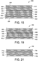
- FIG. 15 is a schematic cross-sectional view of a filter media 500 according to a different embodiment of the present invention.
- the filter media 500 is similarly constructed as the filter media 100, but includes six layers of substrate 502, 504, 506, 508, 510, 512, each of which carrying fine fibers 514, 516, 518, 520, 522, 524, instead of ten layers of substrate carrying fine fibers.
- the most upstream composite media layer comprising the substrate layer 512 and fine fibers 524 is reversed such that the fine fibers 524 face the fine fibers 522 forming a fine fiber-fine fiber interface.
- the substrate 512 provides an upstream surface 526 of the filter media 500, thus fine fibers are not exposed and protected.
- test samples of the filter media 500 were prepared in a laboratory. Test samples of all embodiments described herein are prepared to have a sample area of 0.1 ft 2 .
- a bi-component fiber scrim comprising a high melt polyester core and a low melt polyester sheath having a basis weight of 35.0 GSY was used for the each of the substrate layers 502, 504, 506, 508, 510, 512.
- the fine fibers were formed via an electrospinning process from a polymeric solution comprising PA-6 and deposited on each of the substrate layers. On the substrate 512, about 0.05 g/m 2 of the PA-6 nanofibers 524 having an average fiber diameter of 0.08 micron were formed and deposited.
- This level of fine fiber basis weight provides a linear fine fiber coverage of about 9176 km/m 2 (5,702 miles/m 2 .)
- On the substrate 510 about 0.15 g/m 2 of the PA-6 nanofibers 522 having an average fiber diameter of 0.08 micron were formed and deposited.
- This level of fine fiber basis weight provides a linear fine fiber coverage of about 27,530 km/m 2 (17,106 miles/m 2 .)
- This level of fine fiber basis weight provides a linear fine fiber coverage of about 41,290 km/ m 2 (25,659 miles/m 2 ) on each substrate.
- the filter media 500 includes a total fine fiber basis weight of about 1.1 g/m 2 , which provides about 201,866 km/ m 2 (125,444 miles/m 2 ) of linear fiber coverage.
- the six substrate layers carrying the fine fibers were arranged as shown in FIG. 15 such that the substrate layer 512 forms the upstream surface 526 and the substrate layer 502 forms the downstream surface 528.
- the six composite media layers were heated and compressed via a calendering roller as described in the previous embodiments to form the composite filter media 500.
- Test samples of the filter media 500 were prepared and tested for efficiency and dust holding capacity according to the ISO 16889 international standard for multi-pass method for evaluating filtration performance. All tests were performed using a hydraulic fluid Mil-H-5606 having a viscosity at the test temperature of 15 mm2/s loaded with ISOMTD test dust.
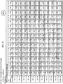
- FIG. 16 shows particle counts per mL and filtration ratio at 10%, 20%, 30%, 40%, 50%, 60%, 70%, 80%, 90%, and 100% time intervals during the 6-hour test period.
- the test results were converted to a fluid cleanliness rating according to ISO 4406:99 cleanliness code (R4/R6/R14), the cleanliness rating at 10% time interval is 7/5/0, at 100% is 13/11/7, and average is 6/4/0.
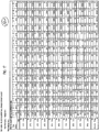
- FIG. 17 shows particle counts per mL and filtration ratio test results.
- the cleanliness rating at 10% time interval is 7/6/0, at 100% is 19/18/14, and average is 12/11/7.
- Test samples of the filter media 500 for the third test were prepared in a laboratory similarly as the test samples for the first test and the second test. However, the fine fiber basis weight of each substrate layer was changed. On each of the substrates 510 and 512, about 0.05 g/m 2 of the PA-6 nanofibers 522, 524 having an average fiber diameter of 0.08 micron were formed and deposited. This level of fine fiber basis weight provides a linear fine fiber coverage of about 9176 km/m 2 (5,702 miles/m 2 ) on the each substrate. On the substrate 508, about 0.075 g/m 2 of the PA-6 nanofibers 520 having an average fiber diameter of 0.08 micron were formed and deposited.
- This level of fine fiber basis weight provides a linear fine fiber coverage of about 13,760 km/m 2 (8,553 miles/m 2 .)
- This level of fine fiber basis weight provides a linear fine fiber coverage of about 16,520 km/m 2 (10,263 miles/m 2 .)
- On the substrate 504 about 0.15 g/m 2 of the PA-6 nanofibers 516 having an average fiber diameter of 0.08 micron were formed and deposited.
- This level of fine fiber basis weight provides a linear fine fiber coverage of about 27,530 km/m 2 (17,106 miles/m 2 .)
- This level of fine fiber basis weight provides a linear fine fiber coverage of about 41,290 km/m 2 (25,659 miles/m 2 .)
- the filter media 500 includes a total fine fiber basis weight of about 0.64 g/m 2 , which provides about 117,452 km/m 2 (72,985 miles/m 2 ) of linear fiber coverage.
- the test fluid having a base upstream contaminant concentration of 15.00 mg/L was used at a flow rate of 0.26 GPM.
- FIG. 18 shows particle counts per mL and filtration ratio test results. The cleanliness rating at 10% time interval is 11/9/4, at 100% is 17/16/11, and average is 16/15/10.
- FIG. 19 is a schematic cross-sectional view of a filter media 600 according to a different embodiment of the present invention.
- the filter media 600 is similarly constructed as the filter media 500 of FIG. 15 , however the filter media 600 include five substrate layers 602, 604, 606, 608, 610 and five fine fiber layers 612, 614, 616, 618, 620.
- Test samples of the filter media 600 for the fourth test were prepared in a laboratory similarly as the previous test samples. For these test samples, about 0.15 g/m 2 of the PA-6 nanofibers 612, 614, 616, 618, 620 having an average fiber diameter of 0.08 micron were formed and deposited on each of the substrate layers 602, 604, 606, 608, 610.
- This level of fine fiber basis weight provides a linear fine fiber coverage of about 27,530 km/m 2 (17,106 miles/m 2 ) on each substrate.
- the filter media 600 includes a total fine fiber basis weight of about 0.75 g/m 2 , which provides about 137,650 km/m 2 (85,530 miles/m 2 ) of linear fiber coverage.
- FIG. 20 shows particle counts per mL and filtration ratio test results.
- the cleanliness rating at 10% time interval is 10/8/0, at 100% is 16/13/11, and average is 14/12/8.
- FIG. 21 is a schematic cross-sectional view of a filter media 700 according to yet another embodiment of the present invention.
- the filter media 700 is similarly constructed as the filter media 500 of FIG. 15 , however the filter media 700 include three substrate layers 702, 704, 706 and three fine fiber layers 708, 710, 712.
- Test samples of the filter media 700 for the fifth test were prepared in a laboratory similarly as the previous test samples. For these test samples, about 0.075 g/m 2 of the PA-6 nanofibers 712 having an average fiber diameter of 0.08 micron were formed and deposited on the substrate 706.
- This level of fine fiber basis weight provides a linear fine fiber coverage of about 13,760 km/m 2 (8,553 miles/m 2 .)
- This level of fine fiber basis weight provides a linear fine fiber coverage of about 16,520 km/m 2 (10,263 miles/m 2 .) .
- the filter media 700 includes a total fine fiber basis weight of about 0.315 g/m 2 , which provides about 57,810 km/m 2 (35,922 miles/m 2 ) of linear fiber coverage.
- the test fluid having a base upstream contaminant concentration of 5.00 mg/L was used at a flow rate of 0.26 GPM.
- FIG. 22 shows particle counts per mL and filtration ratio test results. The cleanliness rating at 10% time interval is 11/10/5, at 100% is 11/9/4, and average is 9/8/0.
- Tubular depth filters such as those shown in FIGS. 1-1(A) , including fine fiber multilayer filter media sheets, such as those shown in FIGS. 15, 19, 21 , were prepared and tested for efficiency and dust holding according to the ISO 16889 international standard for multi-pass method for evaluating filtration performance. All tests were performed using a hydraulic fluid Mil-H-5606 having a viscosity at the test temperature of 15 mm 2 /s loaded with ISOMTD test dust.
- the tubular depth filters including the fine fiber multilayer filter media sheets according to embodiments of the present invention had superior efficiency test results than the standard tubular depth filter (benchmark).
- the standard tubular depth filter was prepared similarly as the method described and shown in FIGS. 3 and 6 using a 4-station winding machine.
- Station 2 fed an interlay of microfiberglass sheet on a polyester sheet to form the standard tubular depth filter.
- the test fluid having a base upstream contaminant concentration of 5.00 mg/L was used at a flow rate of 2.4 GPM.
- FIG. 24 shows particle counts per mL and filtration ratio test results. The cleanliness rating at 10% time interval is 15/14/9, at 100% is 16/14/10, and average is 16/15/9.
- a tubular depth filter media including fine fiber multilayer medias was prepared using the 4-station winding machine similarly as the standard tubular depth media.
- a fine fiber multilayer filter media of FIG. 19 was used as a replacement for station 2 instead of the microfiberglass sheet and a fine fiber multilayer filter media of FIG. 21 was used as the interleaf for station 3 instead of the PEM sheet.
- the station 2 fine fiber replacement media about 0.225 g/m 2 of the PA-6 nanofibers 612, 614 having an average fiber diameter of 0.08 micron were formed and deposited on each of the substrate layers 602, 604. This level of fine fiber basis weight provides a linear fine fiber coverage of about 41,290 km/m 2 on each substrate. On substrate 606, about 0.015 g/m 2 of PA-6 nanofibers 616 having an average fiber diameter of 0.08 micron were formed and deposited. This level of fine fiber basis weight provides a linear fine fiber coverage of about 27,530 km/m 2 . On each of substrate layers 608, 610, about 0.075 g/m 2 of the PA-6 nanofibers 618, 620 having an average fiber diameter of 0.08 micron were formed and deposited.
- the filter media 600 includes a total fine fiber basis weight of about 0.75 g/m 2 , which provides about 137,630 km/m 2 of linear fiber coverage.
- the station 3 fine fiber replacement media about 0.09 g/m 2 of the PA-6 nanofibers 708 having an average fiber diameter of 0.08 micron were formed and deposited on the substrate layer 702. This level of fine fiber basis weight provides a linear fine fiber coverage of about 16,520 km/m 2 . On substrate 704, about 0.075 g/m 2 of PA-6 nanofibers 710 having an average fiber diameter of 0.08 micron were formed and deposited. This level of fine fiber basis weight provides a linear fine fiber coverage of about 13,760 km/m 2 . On substrate 706, about 0.05 g/m 2 of the PA-6 nanofibers 712 having an average fiber diameter of 0.08 micron were formed and deposited.
- the filter media 700 includes a total fine fiber basis weight of about 0.215 g/m 2 , which provides about 39,456 km/m 2 of linear fiber coverage.
- FIG. 25 shows particle counts per mL and filtration ratio test results.
- the cleanliness rating at 10% time interval is 10/7/0, at 100% is 16/15/7, and average is 14/12/4.
- FIG. 26 shows particle counts per mL and filtration ratio test results.
- the cleanliness rating at 10% time interval is 8/6/0, at 100% is 16/14/5, and average is 13/11/0.
Landscapes
- Chemical & Material Sciences (AREA)
- Engineering & Computer Science (AREA)
- Chemical Kinetics & Catalysis (AREA)
- Nanotechnology (AREA)
- Crystallography & Structural Chemistry (AREA)
- Condensed Matter Physics & Semiconductors (AREA)
- General Physics & Mathematics (AREA)
- Materials Engineering (AREA)
- Composite Materials (AREA)
- Physics & Mathematics (AREA)
- Filtering Materials (AREA)
- Nonwoven Fabrics (AREA)
- Solid-Sorbent Or Filter-Aiding Compositions (AREA)
- Artificial Filaments (AREA)
- Multicomponent Fibers (AREA)
- Spinning Methods And Devices For Manufacturing Artificial Fibers (AREA)
Applications Claiming Priority (5)
| Application Number | Priority Date | Filing Date | Title |
|---|---|---|---|
| US30848810P | 2010-02-26 | 2010-02-26 | |
| US33046210P | 2010-05-03 | 2010-05-03 | |
| US38348710P | 2010-09-16 | 2010-09-16 | |
| US38356910P | 2010-09-16 | 2010-09-16 | |
| PCT/US2011/026096 WO2011106540A2 (en) | 2010-02-26 | 2011-02-24 | Non-pleated tubular depth filter having fine fiber filtration media |
Publications (3)
| Publication Number | Publication Date |
|---|---|
| EP2539053A2 EP2539053A2 (en) | 2013-01-02 |
| EP2539053A4 EP2539053A4 (en) | 2013-08-28 |
| EP2539053B1 true EP2539053B1 (en) | 2019-04-10 |
Family
ID=44504740
Family Applications (4)
| Application Number | Title | Priority Date | Filing Date |
|---|---|---|---|
| EP11748074.9A Active EP2539053B1 (en) | 2010-02-26 | 2011-02-24 | Non-pleated tubular depth filter having fine fiber filtration media |
| EP11748071.5A Withdrawn EP2539054A4 (en) | 2010-02-26 | 2011-02-24 | FINE FILTER MEDIA FOR LIQUID PARTICLES |
| EP11748070.7A Withdrawn EP2539056A4 (en) | 2010-02-26 | 2011-02-24 | COMPOUNDED NANOFIBER COMPOSITE ENVIRONMENT |
| EP11748073.1A Withdrawn EP2539055A4 (en) | 2010-02-26 | 2011-02-24 | EXPANDED COMPOSITE FILTER MEDIUM COMPRISING A NANOFIBRA MATRIX AND METHOD |
Family Applications After (3)
| Application Number | Title | Priority Date | Filing Date |
|---|---|---|---|
| EP11748071.5A Withdrawn EP2539054A4 (en) | 2010-02-26 | 2011-02-24 | FINE FILTER MEDIA FOR LIQUID PARTICLES |
| EP11748070.7A Withdrawn EP2539056A4 (en) | 2010-02-26 | 2011-02-24 | COMPOUNDED NANOFIBER COMPOSITE ENVIRONMENT |
| EP11748073.1A Withdrawn EP2539055A4 (en) | 2010-02-26 | 2011-02-24 | EXPANDED COMPOSITE FILTER MEDIUM COMPRISING A NANOFIBRA MATRIX AND METHOD |
Country Status (14)
| Country | Link |
|---|---|
| US (4) | US20110210060A1 (enExample) |
| EP (4) | EP2539053B1 (enExample) |
| JP (3) | JP2013521106A (enExample) |
| KR (3) | KR20130009793A (enExample) |
| CN (4) | CN102869433B (enExample) |
| AU (4) | AU2011220740B2 (enExample) |
| BR (4) | BR112012021549A2 (enExample) |
| CA (4) | CA2790415A1 (enExample) |
| ES (1) | ES2731684T3 (enExample) |
| MX (4) | MX349758B (enExample) |
| MY (2) | MY164152A (enExample) |
| RU (1) | RU2563273C2 (enExample) |
| SG (3) | SG184784A1 (enExample) |
| WO (4) | WO2011106534A2 (enExample) |
Cited By (1)
| Publication number | Priority date | Publication date | Assignee | Title |
|---|---|---|---|---|
| RU2835489C1 (ru) * | 2024-07-05 | 2025-02-25 | Акционерное общество "Тион Умный микроклимат" | Объемный фильтр из нетканого самонесущего материала и способ его изготовления |
Families Citing this family (83)
| Publication number | Priority date | Publication date | Assignee | Title |
|---|---|---|---|---|
| US8950587B2 (en) | 2009-04-03 | 2015-02-10 | Hollingsworth & Vose Company | Filter media suitable for hydraulic applications |
| WO2013035742A1 (ja) * | 2011-09-05 | 2013-03-14 | 日産化学工業株式会社 | 精製された珪酸アルカリ水溶液及びシリカゾルの製造方法 |
| TWI576146B (zh) | 2011-09-16 | 2017-04-01 | 日產化學工業股份有限公司 | 經精製的活性矽酸液及二氧化矽溶膠之製造方法 |
| JP2013083192A (ja) * | 2011-10-07 | 2013-05-09 | Denso Corp | 燃料フィルタ装置 |
| CZ2011762A3 (cs) * | 2011-11-23 | 2013-04-24 | Technická univerzita v Liberci | Prostredek pro zabránení pruniku ropy do vody a/nebo pro separaci ropy obsazené ve vode |
| US10058808B2 (en) | 2012-10-22 | 2018-08-28 | Cummins Filtration Ip, Inc. | Composite filter media utilizing bicomponent fibers |
| US9149749B2 (en) | 2012-11-13 | 2015-10-06 | Hollingsworth & Vose Company | Pre-coalescing multi-layered filter media |
| US11090590B2 (en) | 2012-11-13 | 2021-08-17 | Hollingsworth & Vose Company | Pre-coalescing multi-layered filter media |
| US9149748B2 (en) | 2012-11-13 | 2015-10-06 | Hollingsworth & Vose Company | Multi-layered filter media |
| WO2014116946A1 (en) * | 2013-01-25 | 2014-07-31 | Xanofi, Inc. | Wet laid non-woven substrate containing polymeric nanofibers |
| CN105228731A (zh) * | 2013-03-15 | 2016-01-06 | 佩科平面美国公司 | 改性的表面能非织造过滤器元件 |
| KR101601175B1 (ko) * | 2013-08-06 | 2016-03-08 | 주식회사 아모그린텍 | 주름 필터 및 그 제조 방법 |
| KR101625083B1 (ko) * | 2013-10-07 | 2016-06-07 | (주)에프티이앤이 | 나일론 나노섬유를 포함하는 필터 및 이의 제조방법 |
| WO2015053444A1 (ko) * | 2013-10-07 | 2015-04-16 | (주)에프티이앤이 | 기재 사이에 나노섬유를 포함하는 필터 및 이의 제조방법 |
| WO2015053442A1 (ko) * | 2013-10-07 | 2015-04-16 | (주)에프티이앤이 | 나노섬유를 포함하는 필터 및 이의 제조방법 |
| KR101586730B1 (ko) * | 2013-10-07 | 2016-01-19 | (주)에프티이앤이 | 폴리비닐리덴 플루오라이드 나노섬유를 포함하는 필터 및 이의 제조방법 |
| US9433878B2 (en) | 2013-10-31 | 2016-09-06 | General Electric Company | Electrostatic coalescer for coalescing a dispersed phase from a continuous phase in an emulsion |
| US9573079B2 (en) | 2013-10-31 | 2017-02-21 | General Electric Company | Article and apparatus for enhancing the coalescence of a dispersed phase from a continuous phase in an emulsion |
| US11845019B2 (en) | 2013-11-06 | 2023-12-19 | Bl Technologies, Inc. | Large format melt-blown depth filter cartridge |
| US10179426B2 (en) | 2013-11-06 | 2019-01-15 | Bl Technologies, Inc. | Large format melt-blown depth filter cartridge |
| CN103706149B (zh) * | 2014-01-13 | 2016-03-09 | 上海米素环保科技有限公司 | 模块化组合高效分离设备 |
| US10106452B2 (en) | 2014-02-14 | 2018-10-23 | Superior Fibers, Llc | System and method of continuous glass filament manufacture |
| US9446978B2 (en) | 2014-02-14 | 2016-09-20 | Charles Douglas Spitler | System and method for continuous strand fiberglass media processing |
| US10351462B1 (en) | 2014-02-14 | 2019-07-16 | Superior Fibers, Llc | Method of manufacturing fiberglass filtration media |
| US20170151514A1 (en) * | 2014-03-31 | 2017-06-01 | Unitika Ltd. | Air filter material |
| US10399024B2 (en) | 2014-05-15 | 2019-09-03 | Hollingsworth & Vose Company | Surface modified filter media |
| US10195542B2 (en) | 2014-05-15 | 2019-02-05 | Hollingsworth & Vose Company | Surface modified filter media |
| CN104069665B (zh) * | 2014-07-23 | 2015-10-07 | 江苏永尚能源科技有限公司 | 具有自清洗装置的过滤器 |
| DE102015002672A1 (de) * | 2015-03-03 | 2016-09-08 | Mann + Hummel Gmbh | Filtermedium und Filterelement mit einem Filtermedium |
| WO2016160613A1 (en) | 2015-03-27 | 2016-10-06 | Spitler Charles Douglas | Skin stiffness characteristics and loft control production system and method with variable moisture content in input fiberglass |
| US10828587B2 (en) | 2015-04-17 | 2020-11-10 | Hollingsworth & Vose Company | Stable filter media including nanofibers |
| US11266936B2 (en) | 2015-04-28 | 2022-03-08 | Bl Technologies, Inc. | Melt-blown depth filter element, method and machine of making it |
| WO2016183107A1 (en) | 2015-05-11 | 2016-11-17 | Spitler Charles Douglas | A preparation for fiberglass air filtration media |
| WO2016210153A1 (en) | 2015-06-26 | 2016-12-29 | Donaldson Company, Inc. | Composite media for fuel streams |
| KR101579938B1 (ko) * | 2015-07-24 | 2015-12-28 | (주)에프티이앤이 | 폴리비닐리덴 플루오라이드 나노섬유를 포함하는 필터 |
| CN112387007A (zh) * | 2015-08-22 | 2021-02-23 | 奥斯龙明士克公司 | 具有提高效率的用于从水-烃乳液中除去水的燃料水分离过滤介质 |
| US10315141B2 (en) | 2015-10-29 | 2019-06-11 | Parker Hannifin Filtration (Us), Inc. | Thermally bonded multi-layer felt filtration media |
| RU2637952C2 (ru) * | 2016-01-29 | 2017-12-08 | Российская Федерация, от имени которой выступает ФОНД ПЕРСПЕКТИВНЫХ ИССЛЕДОВАНИЙ | Фильтрующий материал и способ его получения |
| US20170225109A1 (en) * | 2016-02-10 | 2017-08-10 | United Air Specialists, Inc. | Nested filter for use in a mist coalescer unit |
| RU2639702C2 (ru) * | 2016-02-24 | 2017-12-21 | Общество С Ограниченной Ответственностью "Тион Инжиниринг" | Объемный фильтр из нетканого самонесущего материала |
| EP3436268B1 (en) | 2016-03-30 | 2021-05-05 | Parker-Hannifin Corporation | Direct deposition of a nanofiber on a textile substrate |
| KR102211574B1 (ko) | 2016-04-19 | 2021-02-03 | 주식회사 엘지화학 | 보조 배터리 팩의 온도 조절 장치 및 방법 |
| WO2017196653A1 (en) | 2016-05-13 | 2017-11-16 | Donaldson Company, Inc. | Filter media, elements, and methods |
| US10625196B2 (en) | 2016-05-31 | 2020-04-21 | Hollingsworth & Vose Company | Coalescing filter media |
| WO2018017701A1 (en) | 2016-07-19 | 2018-01-25 | Cummins Filtration Ip, Inc. | Perforated layer coalescer |
| US10668411B2 (en) | 2016-07-20 | 2020-06-02 | Entegris, Inc. | Depth filtration media with multiple organic and/or inorganic materials |
| CN106360843B (zh) * | 2016-09-22 | 2017-10-31 | 东华大学 | 一种高舒适性纳米纤维自粘防护口罩 |
| BR112019014236A2 (pt) * | 2017-01-23 | 2020-03-17 | Afyx Therapeutics A/S | Método para a fabricação de um produto de duas camadas à base de fibras eletrofiadas |
| US20180243674A1 (en) * | 2017-02-21 | 2018-08-30 | Hollingsworth & Vose Company | Electret-containing filter media |
| US10814261B2 (en) | 2017-02-21 | 2020-10-27 | Hollingsworth & Vose Company | Electret-containing filter media |
| US20180272258A1 (en) * | 2017-03-22 | 2018-09-27 | Hollingsworth & Vose Company | Filter media including a waved filtration layer having a gradient |
| DE102017002957A1 (de) | 2017-03-28 | 2018-10-04 | Mann+Hummel Gmbh | Spinnvliesstoff, Filtermedium, Filterelement und deren Verwendung und Filteranordnung |
| CN110462124B (zh) | 2017-03-28 | 2023-01-31 | 曼·胡默尔有限公司 | 纺粘型无纺布材料、包括纺粘型无纺布材料的物件、过滤介质、过滤元件及其应用 |
| WO2019017848A1 (en) * | 2017-07-20 | 2019-01-24 | Planet Care | METHOD AND DEVICE FOR REMOVING PARTICLES, PREFERABLY MICROFIBERS, WASTEWATER |
| CN110997119B (zh) * | 2017-07-21 | 2022-11-29 | 阿莫绿色技术有限公司 | 过滤器滤材、其制造方法及包括其的过滤器单元 |
| KR20190036606A (ko) | 2017-09-28 | 2019-04-05 | 안홍태 | 접착메쉬테이프를 이용한 에어필터 및 그 제조방법 |
| US11338231B2 (en) | 2017-11-15 | 2022-05-24 | Cummins Filtration Ip, Inc. | Oil management structures in crankcase ventilation |
| US20210086116A1 (en) * | 2018-04-16 | 2021-03-25 | Ahlstrom-Munksjö Oyj | High burst strength wet-laid nonwoven filtration media and process for producing same |
| DE112019002280T5 (de) | 2018-05-03 | 2021-02-04 | Cummins Filtration Ip, Inc. | Verbundfiltermedien mit mehreren faserstrukturen einschliesslich nanofasern |
| WO2020081437A1 (en) | 2018-10-16 | 2020-04-23 | Cummins Filtration Ip, Inc. | Adhesive alloys and filter medias including such adhesive alloys |
| CN109371478B (zh) * | 2018-10-26 | 2021-06-08 | 杭州萧元纺纱有限公司 | 实验用3d堆叠式电纺纤维喷射方法及应用 |
| CN109137095B (zh) * | 2018-10-26 | 2021-11-30 | 邳州市鑫盛创业投资有限公司 | 电纺纤维喷射成形装置的收集台 |
| KR20200062739A (ko) | 2018-11-27 | 2020-06-04 | (주) 웨이브링크 | 개선된 전자가격표시 시스템 및 방법 |
| US11452959B2 (en) | 2018-11-30 | 2022-09-27 | Hollingsworth & Vose Company | Filter media having a fine pore size distribution |
| RU2706981C1 (ru) * | 2019-02-15 | 2019-11-21 | Акционерное общество "Новомет-Пермь" | Способ изготовления скважинного фильтра |
| CN110804205B (zh) * | 2019-09-26 | 2022-05-13 | 上海稀点新材料科技有限公司 | 具有纳米多孔结构的水溶性树脂隔热保温材料及其制备方法 |
| KR20220116146A (ko) | 2019-10-08 | 2022-08-22 | 도날드슨 컴파니, 인코포레이티드 | 혼합된 직경 미세 섬유를 포함하는 필터 매체 층 |
| US11376529B2 (en) * | 2019-11-15 | 2022-07-05 | Ip 33 Ltd | Particle filter system |
| RU2731700C1 (ru) * | 2019-12-13 | 2020-09-08 | Общество С Ограниченной Ответственностью "Тион Инжиниринг" | Блок фильтрации и элемент фильтрации, входящий в его состав |
| US20210229004A1 (en) * | 2020-01-23 | 2021-07-29 | Jonell filtration Products, Inc. | Tubular filter with nonwoven media and method |
| CN116194187A (zh) | 2020-04-02 | 2023-05-30 | 唐纳森公司 | 过滤介质、复合材料以及使用该过滤介质的面罩系统 |
| EP4126295A1 (en) | 2020-04-03 | 2023-02-08 | Donaldson Company, Inc. | Filtration media |
| CN113565714B (zh) * | 2020-04-28 | 2023-03-28 | 清华大学 | 纳米纤维致动器及其制备方法 |
| WO2021224115A1 (de) * | 2020-05-08 | 2021-11-11 | Basf Se | Filter auf basis eines vliesverbundes |
| KR20240099341A (ko) | 2021-10-29 | 2024-06-28 | 도널드선 컴파니 인코포레이티드 | 흡착 매체 |
| KR20250019616A (ko) | 2022-04-08 | 2025-02-10 | 마티브 룩셈부르크 | 나노입자를 혼입한 개구형성된 중합체 시트 |
| KR20250019623A (ko) | 2022-04-08 | 2025-02-10 | 마티브 룩셈부르크 | 이중층 기체 필터 및 시스템 및 그의 제조 방법 |
| KR20250019618A (ko) * | 2022-04-08 | 2025-02-10 | 마티브 룩셈부르크 | 부직 물질 및 부직 물질을 함유하는 제품 |
| WO2023196618A1 (en) | 2022-04-08 | 2023-10-12 | Delstar Technologies, Inc. | Mechanical and electrostatic filter media |
| US12534834B2 (en) | 2022-04-08 | 2026-01-27 | Delstar Technologies, Inc. | Systems and methods for making fibrous materials |
| US20250099887A1 (en) | 2023-02-06 | 2025-03-27 | Fibertex Nonwovens A/S | Filter material comprising a gradient structure nonwoven base layer and a nanofiber top layer |
| CA3230179A1 (en) * | 2023-08-09 | 2025-06-12 | Jonell filtration Products, Inc. | Tubular filter with nonwoven media and method |
| CN122422033A (zh) * | 2023-12-22 | 2026-07-17 | 国立大学法人鹿儿岛大学 | 聚结器系统以及油水分离装置 |
Family Cites Families (92)
| Publication number | Priority date | Publication date | Assignee | Title |
|---|---|---|---|---|
| FR707191A (fr) * | 1929-12-07 | 1931-07-03 | Ver Fur Chemische Ind Ag | Procédé pour fabriquer des fils artificiels |
| GB1346231A (en) | 1970-06-29 | 1974-02-06 | Bayer Ag | Filter made of electrostatically spun fibres |
| JPS5118348Y2 (enExample) * | 1972-01-22 | 1976-05-17 | ||
| GB1459784A (en) * | 1973-04-26 | 1976-12-31 | Croftshaw Engs Ltd | Adsorber apparatus |
| US3994258A (en) * | 1973-06-01 | 1976-11-30 | Bayer Aktiengesellschaft | Apparatus for the production of filters by electrostatic fiber spinning |
| CH570493A5 (enExample) * | 1973-08-16 | 1975-12-15 | Battelle Memorial Institute | |
| JPS5098485A (enExample) * | 1973-12-29 | 1975-08-05 | ||
| US3994285A (en) * | 1974-12-17 | 1976-11-30 | Doll Research, Inc. | Revolving symmetrical magnet assembly and improved method of blood flow detection |
| JPS5219785U (enExample) * | 1975-07-31 | 1977-02-12 | ||
| JPS52120282A (en) * | 1976-04-02 | 1977-10-08 | Taiyo Chuki Kk | Gas purification apparatus |
| EP0162645A1 (en) | 1984-05-11 | 1985-11-27 | Masami Harada | Carbon-fiber-covered material |
| US4765915A (en) * | 1985-05-23 | 1988-08-23 | The Dow Chemical Company | Porous filter media and membrane support means |
| US4759782A (en) * | 1985-07-05 | 1988-07-26 | Pall Corporation | Coalescing filter for removal of liquid aerosols from gaseous streams |
| US4650506A (en) * | 1986-02-25 | 1987-03-17 | Donaldson Company, Inc. | Multi-layered microfiltration medium |
| JP2572068B2 (ja) * | 1986-07-17 | 1997-01-16 | 旭化成工業株式会社 | 補強された油水分離フィルタ− |
| US5827430A (en) * | 1995-10-24 | 1998-10-27 | Perry Equipment Corporation | Coreless and spirally wound non-woven filter element |
| US5672399A (en) * | 1995-11-17 | 1997-09-30 | Donaldson Company, Inc. | Filter material construction and method |
| US6171684B1 (en) * | 1995-11-17 | 2001-01-09 | Donaldson Company, Inc. | Filter material construction and method |
| US5800586A (en) * | 1996-11-08 | 1998-09-01 | Johns Manville International, Inc. | Composite filter media |
| IL119809A (en) * | 1996-12-11 | 2001-06-14 | Nicast Ltd | A device for the production of a complex material for filtration and a method for its application |
| US5782944A (en) * | 1997-03-18 | 1998-07-21 | Purolator Products Air Filtration Company | Moisture resistant air filter |
| WO1999002242A1 (en) * | 1997-07-11 | 1999-01-21 | Donaldson Company, Inc. | Adsorption apparatus and methods |
| EP1028794A1 (en) * | 1997-09-29 | 2000-08-23 | Donaldson Company, Inc. | Filter material construction and method |
| US20030006186A1 (en) * | 1998-10-05 | 2003-01-09 | Pulek John L. | Spiral wound depth filter |
| DE19919809C2 (de) | 1999-04-30 | 2003-02-06 | Fibermark Gessner Gmbh & Co | Staubfilterbeutel, enthaltend Nanofaservlies |
| IL132945A0 (en) | 1999-06-07 | 2001-03-19 | Nicast Ltd | Filtering material and device and method of its manufacture |
| US6521011B1 (en) * | 1999-07-15 | 2003-02-18 | 3M Innovative Properties Company | Self-supporting pleated filter and method of making same |
| US6649547B1 (en) * | 2000-08-31 | 2003-11-18 | Kimberly-Clark Worldwide, Inc. | Integrated nonwoven laminate material |
| CN101173383A (zh) * | 2000-09-05 | 2008-05-07 | 唐纳森公司 | 聚合物,聚合物微米纤维,聚合物纳米纤维和包括过滤器结构的用途 |
| US6673136B2 (en) * | 2000-09-05 | 2004-01-06 | Donaldson Company, Inc. | Air filtration arrangements having fluted media constructions and methods |
| US6743273B2 (en) * | 2000-09-05 | 2004-06-01 | Donaldson Company, Inc. | Polymer, polymer microfiber, polymer nanofiber and applications including filter structures |
| DE10053546A1 (de) * | 2000-10-27 | 2002-05-02 | Angewandte Technik Mbh Greifsw | Portabler elektrochemischer Sauerstoffgenerator |
| US7029620B2 (en) * | 2000-11-27 | 2006-04-18 | The Procter & Gamble Company | Electro-spinning process for making starch filaments for flexible structure |
| US6641773B2 (en) * | 2001-01-10 | 2003-11-04 | The United States Of America As Represented By The Secretary Of The Army | Electro spinning of submicron diameter polymer filaments |
| JP4138367B2 (ja) * | 2001-06-01 | 2008-08-27 | 高砂熱学工業株式会社 | フィルタユニット |
| DE10136256B4 (de) | 2001-07-25 | 2005-03-31 | Helsa-Werke Gmbh & Co. Kg | Vorrichtung zur Herstellung von Fasern in einem elektrostatischen Spinnverfahren |
| US7432514B2 (en) * | 2002-03-26 | 2008-10-07 | International Business Machines Corporation | Method and apparatus for surface potential reflection electron mask lithography |
| US20040038014A1 (en) * | 2002-08-20 | 2004-02-26 | Donaldson Company, Inc. | Fiber containing filter media |
| KR100513602B1 (ko) * | 2003-05-26 | 2005-09-16 | 부산대학교 산학협력단 | 양전하가 부가된 다공성 필터 미디어 제조 장치 및 방법 |
| US7008465B2 (en) * | 2003-06-19 | 2006-03-07 | Donaldson Company, Inc. | Cleanable high efficiency filter media structure and applications for use |
| US7170155B2 (en) * | 2003-06-25 | 2007-01-30 | Intel Corporation | MEMS RF switch module including a vertical via |
| US20050026526A1 (en) * | 2003-07-30 | 2005-02-03 | Verdegan Barry M. | High performance filter media with internal nanofiber structure and manufacturing methodology |
| CZ294274B6 (cs) | 2003-09-08 | 2004-11-10 | Technická univerzita v Liberci | Způsob výroby nanovláken z polymerního roztoku elektrostatickým zvlákňováním a zařízení k provádění způsobu |
| WO2005047597A2 (en) * | 2003-11-07 | 2005-05-26 | Koslow Technlogies Corporation | Fiber-fiber composites |
| KR20050063592A (ko) * | 2003-12-22 | 2005-06-28 | 삼성전자주식회사 | 공기청정기 |
| JP4614669B2 (ja) * | 2004-02-03 | 2011-01-19 | 日本バイリーン株式会社 | 濾過材及びフィルタ |
| US7501003B2 (en) * | 2004-03-02 | 2009-03-10 | Gore Enterprise Holdings | Composite filter media |
| KR100578764B1 (ko) | 2004-03-23 | 2006-05-11 | 김학용 | 상향식 전기방사장치 및 이를 이용하여 제조된 나노섬유 |
| US7134857B2 (en) * | 2004-04-08 | 2006-11-14 | Research Triangle Institute | Electrospinning of fibers using a rotatable spray head |
| KR20060010231A (ko) * | 2004-07-27 | 2006-02-02 | 삼성전자주식회사 | 공기청정기의 필터 살균장치 및 그 제어방법 |
| US8222166B2 (en) | 2004-10-06 | 2012-07-17 | The Research Foundation Of State University Of New York | High flux and low fouling filtration media |
| US7390760B1 (en) | 2004-11-02 | 2008-06-24 | Kimberly-Clark Worldwide, Inc. | Composite nanofiber materials and methods for making same |
| US20060137317A1 (en) * | 2004-12-28 | 2006-06-29 | Bryner Michael A | Filtration media for filtering particulate material from gas streams |
| CZ300797B6 (cs) | 2005-04-11 | 2009-08-12 | Elmarco, S. R. O. | Textilie obsahující alespon jednu vrstvu polymerních nanovláken a zpusob výroby vrstvy polymerních nanovláken z roztoku polymeru elektrostatickým zvláknováním |
| CZ2005226A3 (cs) | 2005-04-11 | 2006-11-15 | Elmarco, S. R. O. | Vrstvená zvukove pohltivá netkaná textilie |
| CZ299537B6 (cs) | 2005-06-07 | 2008-08-27 | Elmarco, S. R. O. | Zpusob a zarízení k výrobe nanovláken z polymerního roztoku elektrostatickým zvláknováním |
| US8454836B2 (en) * | 2005-09-15 | 2013-06-04 | The University Of Akron | Method for removing water from an organic liquid |
| US20070295659A1 (en) * | 2005-09-29 | 2007-12-27 | Sellars Absorbent Materials, Inc. | Filters and methods of manufacturing the same |
| US20070084786A1 (en) * | 2005-10-14 | 2007-04-19 | General Electric Company | Filter, filter media, and methods for making same |
| CZ305244B6 (cs) | 2005-11-10 | 2015-07-01 | Elmarco S.R.O. | Způsob a zařízení k výrobě nanovláken elektrostatickým zvlákňováním roztoků nebo tavenin polymerů |
| CZ297697B6 (cs) | 2005-11-10 | 2007-03-07 | Elmarco, S. R. O. | Filtr pro odstranování fyzikálních a/nebo biologických necistot |
| US8231752B2 (en) * | 2005-11-14 | 2012-07-31 | Cummins Filtration Ip Inc. | Method and apparatus for making filter element, including multi-characteristic filter element |
| US7618702B2 (en) * | 2006-01-17 | 2009-11-17 | Cornell Research Foundation, Inc. | Cellulosic/polyamide composite |
| WO2007095335A2 (en) | 2006-02-13 | 2007-08-23 | Donaldson Company, Inc. | Filter web comprising fine fiber and reactive, adsorptive or absorptive particulate |
| US7537632B2 (en) * | 2006-06-22 | 2009-05-26 | Clarcor Air Filtration Products, Inc. | Panel filter with frame |
| US20080017038A1 (en) * | 2006-07-21 | 2008-01-24 | 3M Innovative Properties Company | High efficiency hvac filter |
| CZ299549B6 (cs) | 2006-09-04 | 2008-08-27 | Elmarco, S. R. O. | Rotacní zvláknovací elektroda |
| JP2008095266A (ja) * | 2006-10-12 | 2008-04-24 | Hodai Lee | ナノ素材を用いた複合繊維フィルター、ナノ素材を用いた複合繊維フィルターの製造装置及びナノ素材を用いた複合繊維フィルターの製造方法 |
| US20080105626A1 (en) * | 2006-11-02 | 2008-05-08 | David Charles Jones | Fuel filter |
| US8062523B2 (en) * | 2006-12-01 | 2011-11-22 | Perry Equipment Corporation | Filter element and methods of manufacturing and using same |
| EP2125149A2 (en) * | 2007-02-23 | 2009-12-02 | Donaldson Company, Inc. | Formed filter element |
| US8202340B2 (en) * | 2007-02-28 | 2012-06-19 | Hollingsworth & Vose Company | Waved filter media and elements |
| US7942948B2 (en) * | 2007-03-05 | 2011-05-17 | Bha Group, Inc. | Filter element including a composite filter media |
| US20080315465A1 (en) * | 2007-03-05 | 2008-12-25 | Alan Smithies | Method of manufacturing composite filter media |
| JP2008258383A (ja) * | 2007-04-04 | 2008-10-23 | Spansion Llc | 半導体装置及びその製造方法 |
| JP4957434B2 (ja) * | 2007-07-30 | 2012-06-20 | Jnc株式会社 | 熱接着性スパンボンド不織布およびこれを用いた繊維製品 |
| US8978899B2 (en) * | 2007-08-01 | 2015-03-17 | Donaldson Company, Inc. | Fluoropolymer fine fiber |
| KR100900387B1 (ko) * | 2007-08-24 | 2009-06-02 | 한국원자력연구원 | 수처리용 필터 및 이의 제조방법 |
| JP2009056388A (ja) * | 2007-08-31 | 2009-03-19 | Panasonic Corp | ガス除去フィルタおよびガス除去フィルタユニット |
| WO2009050392A2 (fr) | 2007-09-26 | 2009-04-23 | France Telecom | Procede de decouverte de la couverture d'un reseau de diffusion par un terminal multimode, produit programme d'ordinateur, signal et terminal correspondants |
| CN101939072B (zh) * | 2007-11-09 | 2017-04-05 | 霍林斯沃思和沃斯有限公司 | 熔喷过滤介质 |
| KR101637612B1 (ko) * | 2007-11-20 | 2016-07-07 | 클라코르 인코포레이션 | 필터 매체의 형성 방법. 및 이를 이용하여 제조된 필터 매체 |
| US7967588B2 (en) * | 2007-11-20 | 2011-06-28 | Clarcor Inc. | Fine fiber electro-spinning equipment, filter media systems and methods |
| US7815427B2 (en) * | 2007-11-20 | 2010-10-19 | Clarcor, Inc. | Apparatus and method for reducing solvent loss for electro-spinning of fine fibers |
| US20090178970A1 (en) * | 2008-01-16 | 2009-07-16 | Ahlstrom Corporation | Coalescence media for separation of water-hydrocarbon emulsions |
| US20090266759A1 (en) * | 2008-04-24 | 2009-10-29 | Clarcor Inc. | Integrated nanofiber filter media |
| US8293105B2 (en) * | 2008-05-29 | 2012-10-23 | Perry Equipment Corporation | Contaminant adsorption filtration media, elements, systems and methods employing wire or other lattice support |
| US8048187B2 (en) * | 2008-06-30 | 2011-11-01 | Baldwin Filters, Inc. | Filter frame attachment and fluted filter having same |
| US20110114554A1 (en) | 2008-07-18 | 2011-05-19 | Clarcor Inc. | Multi-component filter media with nanofiber attachment |
| US8172092B2 (en) * | 2009-01-22 | 2012-05-08 | Clarcor Inc. | Filter having melt-blown and electrospun fibers |
| JP5539407B2 (ja) * | 2009-02-17 | 2014-07-02 | フィルトロナ・ポーラス・テクノロジーズ・コーポレーション | ナノファイバを含む多層流体透過性繊維構造体およびこの構造体の製造方法 |
| JP5711230B2 (ja) * | 2009-08-03 | 2015-04-30 | ドナルドソン カンパニー,インコーポレイティド | テーパ付き縦溝流路を有する縦溝流路付き濾過媒体を形成する方法および装置 |
-
2011
- 2011-02-22 US US13/032,227 patent/US20110210060A1/en not_active Abandoned
- 2011-02-22 US US13/032,327 patent/US20110210061A1/en not_active Abandoned
- 2011-02-22 US US13/032,368 patent/US20110210081A1/en not_active Abandoned
- 2011-02-23 US US13/033,238 patent/US9731966B2/en active Active
- 2011-02-24 AU AU2011220740A patent/AU2011220740B2/en not_active Ceased
- 2011-02-24 CN CN201180011053.8A patent/CN102869433B/zh not_active Expired - Fee Related
- 2011-02-24 JP JP2012555148A patent/JP2013521106A/ja active Pending
- 2011-02-24 CN CN201180021120.4A patent/CN102858439B/zh not_active Expired - Fee Related
- 2011-02-24 JP JP2012555150A patent/JP2013521107A/ja active Pending
- 2011-02-24 MY MYPI2012003816A patent/MY164152A/en unknown
- 2011-02-24 WO PCT/US2011/026088 patent/WO2011106534A2/en not_active Ceased
- 2011-02-24 MX MX2012009878A patent/MX349758B/es active IP Right Grant
- 2011-02-24 MX MX2012009880A patent/MX2012009880A/es not_active Application Discontinuation
- 2011-02-24 SG SG2012060133A patent/SG184784A1/en unknown
- 2011-02-24 JP JP2012555147A patent/JP2013521105A/ja active Pending
- 2011-02-24 WO PCT/US2011/026091 patent/WO2011106535A2/en not_active Ceased
- 2011-02-24 KR KR1020127025078A patent/KR20130009793A/ko not_active Ceased
- 2011-02-24 CA CA2790415A patent/CA2790415A1/en not_active Abandoned
- 2011-02-24 MX MX2012009876A patent/MX2012009876A/es not_active Application Discontinuation
- 2011-02-24 CN CN2011800211280A patent/CN102858441A/zh active Pending
- 2011-02-24 RU RU2012141037/05A patent/RU2563273C2/ru active
- 2011-02-24 BR BR112012021549A patent/BR112012021549A2/pt not_active IP Right Cessation
- 2011-02-24 KR KR1020127025085A patent/KR20130032302A/ko not_active Ceased
- 2011-02-24 MY MYPI2012003814A patent/MY162087A/en unknown
- 2011-02-24 CA CA2790581A patent/CA2790581A1/en not_active Abandoned
- 2011-02-24 BR BR112012021548A patent/BR112012021548A2/pt not_active IP Right Cessation
- 2011-02-24 KR KR1020127025081A patent/KR20130020661A/ko not_active Ceased
- 2011-02-24 AU AU2011220734A patent/AU2011220734B2/en not_active Ceased
- 2011-02-24 BR BR112012021535-3A patent/BR112012021535B1/pt not_active IP Right Cessation
- 2011-02-24 EP EP11748074.9A patent/EP2539053B1/en active Active
- 2011-02-24 AU AU2011220737A patent/AU2011220737B2/en not_active Ceased
- 2011-02-24 SG SG2012059903A patent/SG183299A1/en unknown
- 2011-02-24 SG SG2012062188A patent/SG183446A1/en unknown
- 2011-02-24 CN CN2011800211168A patent/CN102946979A/zh active Pending
- 2011-02-24 EP EP11748071.5A patent/EP2539054A4/en not_active Withdrawn
- 2011-02-24 WO PCT/US2011/026093 patent/WO2011106537A2/en not_active Ceased
- 2011-02-24 WO PCT/US2011/026096 patent/WO2011106540A2/en not_active Ceased
- 2011-02-24 MX MX2012009879A patent/MX2012009879A/es not_active Application Discontinuation
- 2011-02-24 CA CA2791312A patent/CA2791312A1/en not_active Abandoned
- 2011-02-24 BR BR112012021555A patent/BR112012021555A2/pt not_active IP Right Cessation
- 2011-02-24 ES ES11748074T patent/ES2731684T3/es active Active
- 2011-02-24 EP EP11748070.7A patent/EP2539056A4/en not_active Withdrawn
- 2011-02-24 CA CA2790425A patent/CA2790425C/en active Active
- 2011-02-24 EP EP11748073.1A patent/EP2539055A4/en not_active Withdrawn
- 2011-02-24 AU AU2011220735A patent/AU2011220735B2/en not_active Ceased
Non-Patent Citations (1)
| Title |
|---|
| None * |
Cited By (1)
| Publication number | Priority date | Publication date | Assignee | Title |
|---|---|---|---|---|
| RU2835489C1 (ru) * | 2024-07-05 | 2025-02-25 | Акционерное общество "Тион Умный микроклимат" | Объемный фильтр из нетканого самонесущего материала и способ его изготовления |
Also Published As
Similar Documents
| Publication | Publication Date | Title |
|---|---|---|
| US9731966B2 (en) | Non-pleated tubular depth filter having fine fiber filtration media | |
| EP2321029B1 (en) | Multi-component filter media with nanofiber attachment | |
| US8172092B2 (en) | Filter having melt-blown and electrospun fibers | |
| US20090266759A1 (en) | Integrated nanofiber filter media |
Legal Events
| Date | Code | Title | Description |
|---|---|---|---|
| PUAI | Public reference made under article 153(3) epc to a published international application that has entered the european phase |
Free format text: ORIGINAL CODE: 0009012 |
|
| 17P | Request for examination filed |
Effective date: 20120831 |
|
| AK | Designated contracting states |
Kind code of ref document: A2 Designated state(s): AL AT BE BG CH CY CZ DE DK EE ES FI FR GB GR HR HU IE IS IT LI LT LU LV MC MK MT NL NO PL PT RO RS SE SI SK SM TR |
|
| DAX | Request for extension of the european patent (deleted) | ||
| A4 | Supplementary search report drawn up and despatched |
Effective date: 20130726 |
|
| RIC1 | Information provided on ipc code assigned before grant |
Ipc: B01D 39/16 20060101ALI20130722BHEP Ipc: B01D 69/10 20060101ALI20130722BHEP Ipc: B01D 69/12 20060101AFI20130722BHEP Ipc: B01D 69/02 20060101ALI20130722BHEP |
|
| GRAP | Despatch of communication of intention to grant a patent |
Free format text: ORIGINAL CODE: EPIDOSNIGR1 |
|
| STAA | Information on the status of an ep patent application or granted ep patent |
Free format text: STATUS: GRANT OF PATENT IS INTENDED |
|
| GRAJ | Information related to disapproval of communication of intention to grant by the applicant or resumption of examination proceedings by the epo deleted |
Free format text: ORIGINAL CODE: EPIDOSDIGR1 |
|
| GRAP | Despatch of communication of intention to grant a patent |
Free format text: ORIGINAL CODE: EPIDOSNIGR1 |
|
| INTG | Intention to grant announced |
Effective date: 20180703 |
|
| INTG | Intention to grant announced |
Effective date: 20180710 |
|
| GRAJ | Information related to disapproval of communication of intention to grant by the applicant or resumption of examination proceedings by the epo deleted |
Free format text: ORIGINAL CODE: EPIDOSDIGR1 |
|
| GRAP | Despatch of communication of intention to grant a patent |
Free format text: ORIGINAL CODE: EPIDOSNIGR1 |
|
| INTG | Intention to grant announced |
Effective date: 20180726 |
|
| GRAJ | Information related to disapproval of communication of intention to grant by the applicant or resumption of examination proceedings by the epo deleted |
Free format text: ORIGINAL CODE: EPIDOSDIGR1 |
|
| GRAP | Despatch of communication of intention to grant a patent |
Free format text: ORIGINAL CODE: EPIDOSNIGR1 |
|
| INTG | Intention to grant announced |
Effective date: 20180823 |
|
| INTG | Intention to grant announced |
Effective date: 20180920 |
|
| GRAJ | Information related to disapproval of communication of intention to grant by the applicant or resumption of examination proceedings by the epo deleted |
Free format text: ORIGINAL CODE: EPIDOSDIGR1 |
|
| GRAP | Despatch of communication of intention to grant a patent |
Free format text: ORIGINAL CODE: EPIDOSNIGR1 |
|
| INTG | Intention to grant announced |
Effective date: 20181120 |
|
| GRAS | Grant fee paid |
Free format text: ORIGINAL CODE: EPIDOSNIGR3 |
|
| GRAA | (expected) grant |
Free format text: ORIGINAL CODE: 0009210 |
|
| STAA | Information on the status of an ep patent application or granted ep patent |
Free format text: STATUS: THE PATENT HAS BEEN GRANTED |
|
| AK | Designated contracting states |
Kind code of ref document: B1 Designated state(s): AL AT BE BG CH CY CZ DE DK EE ES FI FR GB GR HR HU IE IS IT LI LT LU LV MC MK MT NL NO PL PT RO RS SE SI SK SM TR |
|
| REG | Reference to a national code |
Ref country code: GB Ref legal event code: FG4D |
|
| REG | Reference to a national code |
Ref country code: CH Ref legal event code: EP Ref country code: AT Ref legal event code: REF Ref document number: 1117929 Country of ref document: AT Kind code of ref document: T Effective date: 20190415 |
|
| REG | Reference to a national code |
Ref country code: IE Ref legal event code: FG4D |
|
| REG | Reference to a national code |
Ref country code: DE Ref legal event code: R096 Ref document number: 602011057966 Country of ref document: DE |
|
| REG | Reference to a national code |
Ref country code: NL Ref legal event code: MP Effective date: 20190410 |
|
| REG | Reference to a national code |
Ref country code: LT Ref legal event code: MG4D |
|
| REG | Reference to a national code |
Ref country code: AT Ref legal event code: MK05 Ref document number: 1117929 Country of ref document: AT Kind code of ref document: T Effective date: 20190410 |
|
| PG25 | Lapsed in a contracting state [announced via postgrant information from national office to epo] |
Ref country code: NL Free format text: LAPSE BECAUSE OF FAILURE TO SUBMIT A TRANSLATION OF THE DESCRIPTION OR TO PAY THE FEE WITHIN THE PRESCRIBED TIME-LIMIT Effective date: 20190410 |
|
| PG25 | Lapsed in a contracting state [announced via postgrant information from national office to epo] |
Ref country code: LT Free format text: LAPSE BECAUSE OF FAILURE TO SUBMIT A TRANSLATION OF THE DESCRIPTION OR TO PAY THE FEE WITHIN THE PRESCRIBED TIME-LIMIT Effective date: 20190410 Ref country code: HR Free format text: LAPSE BECAUSE OF FAILURE TO SUBMIT A TRANSLATION OF THE DESCRIPTION OR TO PAY THE FEE WITHIN THE PRESCRIBED TIME-LIMIT Effective date: 20190410 Ref country code: SE Free format text: LAPSE BECAUSE OF FAILURE TO SUBMIT A TRANSLATION OF THE DESCRIPTION OR TO PAY THE FEE WITHIN THE PRESCRIBED TIME-LIMIT Effective date: 20190410 Ref country code: PT Free format text: LAPSE BECAUSE OF FAILURE TO SUBMIT A TRANSLATION OF THE DESCRIPTION OR TO PAY THE FEE WITHIN THE PRESCRIBED TIME-LIMIT Effective date: 20190910 Ref country code: NO Free format text: LAPSE BECAUSE OF FAILURE TO SUBMIT A TRANSLATION OF THE DESCRIPTION OR TO PAY THE FEE WITHIN THE PRESCRIBED TIME-LIMIT Effective date: 20190710 Ref country code: FI Free format text: LAPSE BECAUSE OF FAILURE TO SUBMIT A TRANSLATION OF THE DESCRIPTION OR TO PAY THE FEE WITHIN THE PRESCRIBED TIME-LIMIT Effective date: 20190410 Ref country code: AL Free format text: LAPSE BECAUSE OF FAILURE TO SUBMIT A TRANSLATION OF THE DESCRIPTION OR TO PAY THE FEE WITHIN THE PRESCRIBED TIME-LIMIT Effective date: 20190410 |
|
| REG | Reference to a national code |
Ref country code: ES Ref legal event code: FG2A Ref document number: 2731684 Country of ref document: ES Kind code of ref document: T3 Effective date: 20191118 |
|
| PG25 | Lapsed in a contracting state [announced via postgrant information from national office to epo] |
Ref country code: BG Free format text: LAPSE BECAUSE OF FAILURE TO SUBMIT A TRANSLATION OF THE DESCRIPTION OR TO PAY THE FEE WITHIN THE PRESCRIBED TIME-LIMIT Effective date: 20190710 Ref country code: LV Free format text: LAPSE BECAUSE OF FAILURE TO SUBMIT A TRANSLATION OF THE DESCRIPTION OR TO PAY THE FEE WITHIN THE PRESCRIBED TIME-LIMIT Effective date: 20190410 Ref country code: RS Free format text: LAPSE BECAUSE OF FAILURE TO SUBMIT A TRANSLATION OF THE DESCRIPTION OR TO PAY THE FEE WITHIN THE PRESCRIBED TIME-LIMIT Effective date: 20190410 Ref country code: PL Free format text: LAPSE BECAUSE OF FAILURE TO SUBMIT A TRANSLATION OF THE DESCRIPTION OR TO PAY THE FEE WITHIN THE PRESCRIBED TIME-LIMIT Effective date: 20190410 Ref country code: GR Free format text: LAPSE BECAUSE OF FAILURE TO SUBMIT A TRANSLATION OF THE DESCRIPTION OR TO PAY THE FEE WITHIN THE PRESCRIBED TIME-LIMIT Effective date: 20190711 |
|
| PG25 | Lapsed in a contracting state [announced via postgrant information from national office to epo] |
Ref country code: AT Free format text: LAPSE BECAUSE OF FAILURE TO SUBMIT A TRANSLATION OF THE DESCRIPTION OR TO PAY THE FEE WITHIN THE PRESCRIBED TIME-LIMIT Effective date: 20190410 Ref country code: IS Free format text: LAPSE BECAUSE OF FAILURE TO SUBMIT A TRANSLATION OF THE DESCRIPTION OR TO PAY THE FEE WITHIN THE PRESCRIBED TIME-LIMIT Effective date: 20190810 |
|
| REG | Reference to a national code |
Ref country code: DE Ref legal event code: R097 Ref document number: 602011057966 Country of ref document: DE |
|
| PG25 | Lapsed in a contracting state [announced via postgrant information from national office to epo] |
Ref country code: DK Free format text: LAPSE BECAUSE OF FAILURE TO SUBMIT A TRANSLATION OF THE DESCRIPTION OR TO PAY THE FEE WITHIN THE PRESCRIBED TIME-LIMIT Effective date: 20190410 Ref country code: RO Free format text: LAPSE BECAUSE OF FAILURE TO SUBMIT A TRANSLATION OF THE DESCRIPTION OR TO PAY THE FEE WITHIN THE PRESCRIBED TIME-LIMIT Effective date: 20190410 Ref country code: EE Free format text: LAPSE BECAUSE OF FAILURE TO SUBMIT A TRANSLATION OF THE DESCRIPTION OR TO PAY THE FEE WITHIN THE PRESCRIBED TIME-LIMIT Effective date: 20190410 Ref country code: CZ Free format text: LAPSE BECAUSE OF FAILURE TO SUBMIT A TRANSLATION OF THE DESCRIPTION OR TO PAY THE FEE WITHIN THE PRESCRIBED TIME-LIMIT Effective date: 20190410 Ref country code: SK Free format text: LAPSE BECAUSE OF FAILURE TO SUBMIT A TRANSLATION OF THE DESCRIPTION OR TO PAY THE FEE WITHIN THE PRESCRIBED TIME-LIMIT Effective date: 20190410 |
|
| PLBE | No opposition filed within time limit |
Free format text: ORIGINAL CODE: 0009261 |
|
| STAA | Information on the status of an ep patent application or granted ep patent |
Free format text: STATUS: NO OPPOSITION FILED WITHIN TIME LIMIT |
|
| PG25 | Lapsed in a contracting state [announced via postgrant information from national office to epo] |
Ref country code: SM Free format text: LAPSE BECAUSE OF FAILURE TO SUBMIT A TRANSLATION OF THE DESCRIPTION OR TO PAY THE FEE WITHIN THE PRESCRIBED TIME-LIMIT Effective date: 20190410 |
|
| REG | Reference to a national code |
Ref country code: DE Ref legal event code: R082 Ref document number: 602011057966 Country of ref document: DE Representative=s name: ARONOVA S.A., LU |
|
| 26N | No opposition filed |
Effective date: 20200113 |
|
| PG25 | Lapsed in a contracting state [announced via postgrant information from national office to epo] |
Ref country code: TR Free format text: LAPSE BECAUSE OF FAILURE TO SUBMIT A TRANSLATION OF THE DESCRIPTION OR TO PAY THE FEE WITHIN THE PRESCRIBED TIME-LIMIT Effective date: 20190410 |
|
| PG25 | Lapsed in a contracting state [announced via postgrant information from national office to epo] |
Ref country code: SI Free format text: LAPSE BECAUSE OF FAILURE TO SUBMIT A TRANSLATION OF THE DESCRIPTION OR TO PAY THE FEE WITHIN THE PRESCRIBED TIME-LIMIT Effective date: 20190410 |
|
| REG | Reference to a national code |
Ref country code: CH Ref legal event code: PL |
|
| REG | Reference to a national code |
Ref country code: BE Ref legal event code: MM Effective date: 20200229 |
|
| PG25 | Lapsed in a contracting state [announced via postgrant information from national office to epo] |
Ref country code: MC Free format text: LAPSE BECAUSE OF FAILURE TO SUBMIT A TRANSLATION OF THE DESCRIPTION OR TO PAY THE FEE WITHIN THE PRESCRIBED TIME-LIMIT Effective date: 20190410 Ref country code: LU Free format text: LAPSE BECAUSE OF NON-PAYMENT OF DUE FEES Effective date: 20200224 |
|
| PG25 | Lapsed in a contracting state [announced via postgrant information from national office to epo] |
Ref country code: LI Free format text: LAPSE BECAUSE OF NON-PAYMENT OF DUE FEES Effective date: 20200229 Ref country code: CH Free format text: LAPSE BECAUSE OF NON-PAYMENT OF DUE FEES Effective date: 20200229 |
|
| PG25 | Lapsed in a contracting state [announced via postgrant information from national office to epo] |
Ref country code: IE Free format text: LAPSE BECAUSE OF NON-PAYMENT OF DUE FEES Effective date: 20200224 |
|
| PG25 | Lapsed in a contracting state [announced via postgrant information from national office to epo] |
Ref country code: BE Free format text: LAPSE BECAUSE OF NON-PAYMENT OF DUE FEES Effective date: 20200229 |
|
| REG | Reference to a national code |
Ref country code: GB Ref legal event code: 732E Free format text: REGISTERED BETWEEN 20210624 AND 20210630 |
|
| REG | Reference to a national code |
Ref country code: DE Ref legal event code: R081 Ref document number: 602011057966 Country of ref document: DE Owner name: PARKER-HANNIFIN CORP., CLEVELAND, US Free format text: FORMER OWNER: CLARCOR INC., FRANKLIN, TENN., US |
|
| PG25 | Lapsed in a contracting state [announced via postgrant information from national office to epo] |
Ref country code: MT Free format text: LAPSE BECAUSE OF FAILURE TO SUBMIT A TRANSLATION OF THE DESCRIPTION OR TO PAY THE FEE WITHIN THE PRESCRIBED TIME-LIMIT Effective date: 20190410 Ref country code: CY Free format text: LAPSE BECAUSE OF FAILURE TO SUBMIT A TRANSLATION OF THE DESCRIPTION OR TO PAY THE FEE WITHIN THE PRESCRIBED TIME-LIMIT Effective date: 20190410 |
|
| PG25 | Lapsed in a contracting state [announced via postgrant information from national office to epo] |
Ref country code: MK Free format text: LAPSE BECAUSE OF FAILURE TO SUBMIT A TRANSLATION OF THE DESCRIPTION OR TO PAY THE FEE WITHIN THE PRESCRIBED TIME-LIMIT Effective date: 20190410 |
|
| REG | Reference to a national code |
Ref country code: ES Ref legal event code: PC2A Owner name: PARKER-HANNIFIN CORPORATION Effective date: 20220909 |
|
| P01 | Opt-out of the competence of the unified patent court (upc) registered |
Effective date: 20230524 |
|
| PGFP | Annual fee paid to national office [announced via postgrant information from national office to epo] |
Ref country code: ES Payment date: 20240301 Year of fee payment: 14 |
|
| PGFP | Annual fee paid to national office [announced via postgrant information from national office to epo] |
Ref country code: DE Payment date: 20240228 Year of fee payment: 14 Ref country code: GB Payment date: 20240227 Year of fee payment: 14 |
|
| PGFP | Annual fee paid to national office [announced via postgrant information from national office to epo] |
Ref country code: IT Payment date: 20240222 Year of fee payment: 14 Ref country code: FR Payment date: 20240226 Year of fee payment: 14 |
|
| REG | Reference to a national code |
Ref country code: DE Ref legal event code: R119 Ref document number: 602011057966 Country of ref document: DE |
|
| GBPC | Gb: european patent ceased through non-payment of renewal fee |
Effective date: 20250224 |
|
| PG25 | Lapsed in a contracting state [announced via postgrant information from national office to epo] |
Ref country code: DE Free format text: LAPSE BECAUSE OF NON-PAYMENT OF DUE FEES Effective date: 20250902 |
|
| PG25 | Lapsed in a contracting state [announced via postgrant information from national office to epo] |
Ref country code: GB Free format text: LAPSE BECAUSE OF NON-PAYMENT OF DUE FEES Effective date: 20250224 |
|
| PG25 | Lapsed in a contracting state [announced via postgrant information from national office to epo] |
Ref country code: IT Free format text: LAPSE BECAUSE OF NON-PAYMENT OF DUE FEES Effective date: 20250224 Ref country code: FR Free format text: LAPSE BECAUSE OF NON-PAYMENT OF DUE FEES Effective date: 20250228 |
|
| REG | Reference to a national code |
Ref country code: ES Ref legal event code: FD2A Effective date: 20260401 |
|
| PG25 | Lapsed in a contracting state [announced via postgrant information from national office to epo] |
Ref country code: ES Free format text: LAPSE BECAUSE OF NON-PAYMENT OF DUE FEES Effective date: 20250225 |