EP2537788A1 - Fadenführungselement für einen Fingerfadenführer - Google Patents
Fadenführungselement für einen Fingerfadenführer Download PDFInfo
- Publication number
- EP2537788A1 EP2537788A1 EP12004381A EP12004381A EP2537788A1 EP 2537788 A1 EP2537788 A1 EP 2537788A1 EP 12004381 A EP12004381 A EP 12004381A EP 12004381 A EP12004381 A EP 12004381A EP 2537788 A1 EP2537788 A1 EP 2537788A1
- Authority
- EP
- European Patent Office
- Prior art keywords
- thread guide
- guide element
- support rods
- element according
- thread
- Prior art date
- Legal status (The legal status is an assumption and is not a legal conclusion. Google has not performed a legal analysis and makes no representation as to the accuracy of the status listed.)
- Granted
Links
- 238000004049 embossing Methods 0.000 claims abstract description 22
- 239000000463 material Substances 0.000 claims abstract description 5
- 238000004381 surface treatment Methods 0.000 claims abstract description 5
- 229910000639 Spring steel Inorganic materials 0.000 claims abstract description 4
- 238000000034 method Methods 0.000 claims abstract description 4
- VYZAMTAEIAYCRO-UHFFFAOYSA-N Chromium Chemical compound [Cr] VYZAMTAEIAYCRO-UHFFFAOYSA-N 0.000 claims abstract description 3
- 239000007769 metal material Substances 0.000 claims abstract description 3
- 238000007747 plating Methods 0.000 claims abstract description 3
- 238000004804 winding Methods 0.000 claims description 10
- 235000013351 cheese Nutrition 0.000 claims description 4
- 238000007493 shaping process Methods 0.000 claims 1
- 238000000465 moulding Methods 0.000 abstract description 2
- 229910052804 chromium Inorganic materials 0.000 abstract 1
- 239000011651 chromium Substances 0.000 abstract 1
- 229920000049 Carbon (fiber) Polymers 0.000 description 10
- 239000004917 carbon fiber Substances 0.000 description 10
- VNWKTOKETHGBQD-UHFFFAOYSA-N methane Chemical compound C VNWKTOKETHGBQD-UHFFFAOYSA-N 0.000 description 9
- 239000000919 ceramic Substances 0.000 description 5
- FYYHWMGAXLPEAU-UHFFFAOYSA-N Magnesium Chemical compound [Mg] FYYHWMGAXLPEAU-UHFFFAOYSA-N 0.000 description 3
- 239000000853 adhesive Substances 0.000 description 3
- 230000001070 adhesive effect Effects 0.000 description 3
- 229910052749 magnesium Inorganic materials 0.000 description 3
- 239000011777 magnesium Substances 0.000 description 3
- 229910001092 metal group alloy Inorganic materials 0.000 description 3
- 230000008878 coupling Effects 0.000 description 2
- 238000010168 coupling process Methods 0.000 description 2
- 238000005859 coupling reaction Methods 0.000 description 2
- 238000005299 abrasion Methods 0.000 description 1
- 238000005452 bending Methods 0.000 description 1
- 230000015572 biosynthetic process Effects 0.000 description 1
- 229910010293 ceramic material Inorganic materials 0.000 description 1
- 230000001419 dependent effect Effects 0.000 description 1
- 238000011161 development Methods 0.000 description 1
- 230000018109 developmental process Effects 0.000 description 1
- 238000006073 displacement reaction Methods 0.000 description 1
- 230000007613 environmental effect Effects 0.000 description 1
- 238000004519 manufacturing process Methods 0.000 description 1
- 230000002441 reversible effect Effects 0.000 description 1
- 230000035939 shock Effects 0.000 description 1
- 239000004753 textile Substances 0.000 description 1
Images
Classifications
-
- B—PERFORMING OPERATIONS; TRANSPORTING
- B65—CONVEYING; PACKING; STORING; HANDLING THIN OR FILAMENTARY MATERIAL
- B65H—HANDLING THIN OR FILAMENTARY MATERIAL, e.g. SHEETS, WEBS, CABLES
- B65H57/00—Guides for filamentary materials; Supports therefor
- B65H57/006—Traversing guides
-
- B—PERFORMING OPERATIONS; TRANSPORTING
- B65—CONVEYING; PACKING; STORING; HANDLING THIN OR FILAMENTARY MATERIAL
- B65H—HANDLING THIN OR FILAMENTARY MATERIAL, e.g. SHEETS, WEBS, CABLES
- B65H54/00—Winding, coiling, or depositing filamentary material
- B65H54/02—Winding and traversing material on to reels, bobbins, tubes, or like package cores or formers
- B65H54/28—Traversing devices; Package-shaping arrangements
- B65H54/2827—Traversing devices with a pivotally mounted guide arm
-
- B—PERFORMING OPERATIONS; TRANSPORTING
- B65—CONVEYING; PACKING; STORING; HANDLING THIN OR FILAMENTARY MATERIAL
- B65H—HANDLING THIN OR FILAMENTARY MATERIAL, e.g. SHEETS, WEBS, CABLES
- B65H57/00—Guides for filamentary materials; Supports therefor
- B65H57/24—Guides for filamentary materials; Supports therefor with wear-resistant surfaces
-
- B—PERFORMING OPERATIONS; TRANSPORTING
- B65—CONVEYING; PACKING; STORING; HANDLING THIN OR FILAMENTARY MATERIAL
- B65H—HANDLING THIN OR FILAMENTARY MATERIAL, e.g. SHEETS, WEBS, CABLES
- B65H2701/00—Handled material; Storage means
- B65H2701/30—Handled filamentary material
- B65H2701/31—Textiles threads or artificial strands of filaments
Definitions
- the invention relates to a thread guide element for a finger thread guide according to the preamble of claim 1.
- Such thread guide elements are fundamentally known in connection with finger thread guides which change a thread running on the surface of a cross-wound bobbin.
- finger thread guides are described with fixed to their body thread guide elements.
- Finger thread guides are known in which the base body consists of a magnesium die-cast part. At the free end of the magnesium body are connected via flexural elastic rods, preferably carbon fiber rods, ceramic thread guide elements. That is, in corresponding holes of the magnesium body are fixed by means of adhesive carbon fiber rods on which, preferably also by an adhesive bond, each designed as a ceramic sleeve thread guide element is attached.
- flexural elastic rods preferably carbon fiber rods
- ceramic thread guide elements are not subject to any significant wear even with aggressive yarn, there is always the risk that the thread guide elements, for example, as a result of bending moments, never the high-frequency laying of a thread can be completely ruled out, easily break off or that the ceramic flakes off the carbon fiber rods.
- Known finger thread guides also have the disadvantage that the adhesive bonds in the region of the carbon fiber rods form mechanical weak points, which can neither be reliably avoided, nor can be subsequently eliminated reasonably inexpensively.
- Finger thread guides are described, each having two trained as a cylindrical hollow body, formed of a metal alloy thread guide elements at the free end of their body, which form a yarn guide fork, in which a running on a cross-wound yarn during the winding process is performed.
- the thread guide elements are either embedded positively or non-positively in the body or stored on additional support rods made of carbon fibers.
- thread guide elements made of a metal alloy has the advantage that this material is much less sensitive to breakage than ceramic.
- thread guide elements made of a metal alloy are less resistant to abrasion, that is, such Fingerfaden intro must be replaced significantly more frequently due to wear on the thread guide elements, as finger thread guides, which have ceramic thread guide elements.
- the invention has the object to develop finger thread guides with interchangeable, relatively inexpensive thread guide elements, wherein the thread guide elements should be designed so that they can be securely fixed on one hand connected to the main body of the finger thread guide support bars, on the other hand, if necessary problem-free are interchangeable.
- This object is achieved by a thread guide element for a finger thread guide, as described in claim 1.
- the thread guide element is a replaceable positionable on support rods, thin-walled embossed part, which consists of a metallic material and has two coupled by a connecting web, slotted sleeves.
- a trained thread guide element not only has the advantage that the embossing part can be fixed securely and always exactly aligned on the support rods, but can also in case of need, that is, if advised after a certain period of operation of the finger thread guide due to wear marks on the thread guide element a change of the thread guide element appears, can be exchanged quickly and easily.
- embossed part tempered spring steel, which is cured after its molding.
- tempered spring steel which is cured after its molding.
- Such made of a tempered spring steel, hardened embossed part is on the one hand insensitive to shock loads and on the other hand also relatively wear-resistant.
- the embossed part is subjected to a surface treatment after curing, with hard chrome plating preferably being used as the surface treatment.
- a hard chromium-plated embossed part is not only characterized by a very low coefficient of friction, which leads to a gentle treatment of the thread to be traversed, but is also relatively insensitive to environmental influences.
- the connecting web has at least one locking contour, which in the assembled state of the embossing part engages a locking projection on the main body of the finger thread guide form fit.
- Such additional positive locking of the embossing part prevents the embossing part during the winding operation with time centrifugal force can shift outward. That is, the detent contour on the embossing part, in conjunction with a latching lug on the main body of the finger thread guide, ensures that the embossing part is reliably positioned on the support rods during its entire service life.
- the slotted sleeves of the embossing part on a clear inner diameter which is matched to the outer diameter of the associated, designed as carbon fiber rods support rods.
- the inner diameter of the slotted sleeves is chosen so that on the one hand in the assembled state, a bias is given, which is sufficiently large to handle the relative forces between sleeves and carbon fiber rods occurring during operation frictionally and on the other hand is small enough to pull up the sleeves on the carbon fiber rods to avoid damage as possible.
- An appropriate dimensioning of the sleeves and support rods allows in case of need, the easy replacement of a worn stamping, but still ensures a reliable locking of the stamping on the support rods.
- a device which facilitates the assembly of the embossing part on the support rods or the disassembly of the embossing part of the support rods.
- a device may have various configurations, but preferably always has a clamping device for fixing the main body of the finger thread guide and a tool for lifting the locking contour of the embossing part of the locking projection of the body and the axial displacement of the embossing part on the support rods.
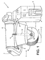
- the Fig. 1 shows a front perspective view of the upper part of a workstation 1 of a cheese producing textile machine.
- workstations 1 usually have a winding unit housing 4 equipped with an input device 3, which, inter alia, also accommodates a workstation-specific control device 5.
- a winding device 6, which essentially consists of a creel 7 for holding a cross-wound bobbin tube 8, a bobbin drive roller 9 and a thread traversing device 2 for traversing a bobbin, is arranged on the winding head housing 4 exists during the winding operation on the cheese reel 8 and a cheese winding yarn.
- the finger thread guide 10 is in turn connected via a fastening and locking element 17 to the motor shaft 18 of a reversible drive device 12, which in turn via a control line 13 with the workstation's own control device. 5 connected is. That is, the finger thread guide 10 can be controlled via the control device 5, so that during the winding process, for example, the thread laying speed and / or the width of the thread laying can be set exactly.
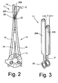
- the Fig. 2 shows a equipped with a thread guide element 11 according to the invention finger thread guide 10, on a larger scale.
- the finger thread guide 10 has a made of a plastic base body 14, in which during the manufacturing process support rods 15, 16 and a fastening and locking element 17 were cast with.
- the carbon fiber rods formed as support pins 15, 16 are significantly longer than the female plastic body 14 receiving them formed. This means that the support rods 15, 16 protrude clearly beyond the base body 14 in the region of the free, narrow end of the main body 14 and thereby form support elements for a thread guide element 11 of the finger thread guide 10.
- the arranged on the support rods 15, 16 thread guide element 11 is inventively designed as a stamping member 19 and has, as in particular also from Figure 3 clearly seen, two slotted sleeves 20A and 20B, which are coupled via a connecting web 21.
- the slots of the sleeves 20A, 20B are arranged so that they point outwards, that is, the slots are positioned so that it is always ensured that during the Fadenchangtechnik the leadership of the thread through the slots can not be affected.
- the slotted sleeves 20A, 20B are also with respect to their clear inner diameter d on the outer diameter D of the support rods 15, 16 is started. That is, the clear inner diameter d of the slotted sleeves 20A, 20B is selected so that the sleeves are fixed after their mounting on the support rods 15, 16 with a certain bias on the support rods.
- the bias is preferably chosen so that on the one hand after assembly ensures a secure hold of the slotted sleeves 20A, 20B on the support pins 15, 16, on the other hand during assembly a relatively easy mounting of the sleeves on the support rods is possible. This means that damage to the support rods 15, 16 made of a carbon fiber material should be avoided as much as possible during assembly of the embossing part 19.
Landscapes
- Guides For Winding Or Rewinding, Or Guides For Filamentary Materials (AREA)
- Spinning Or Twisting Of Yarns (AREA)
Abstract
Description
- Die Erfindung betrifft ein Fadenführungselement für einen Fingerfadenführer gemäß dem Oberbegriff des Anspruchs 1.
- Derartige Fadenführungselemente sind im Zusammenhang mit Fingerfadenführern, die einen auf die Oberfläche einer Kreuzspule auflaufenden Faden changieren, grundsätzlich bekannt.
In derDE 10 2005 059 028 A1 oder derDE 10 2008 053 261 A1 sind beispielsweise Fingerfadenführer mit an ihrem Grundkörper festgelegten Fadenführungselementen beschrieben. - Durch die
DE 10 2008 053 261 A1 sind Fingerfadenführer bekannt, bei denen der Grundkörper aus einem Magnesiumdruckgussteil besteht. An das freie Ende des Magnesiumgrundkörpers sind über biegeelastische Stäbe, vorzugsweise Kohlefaserstäbe, keramische Fadenführungselemente angeschlossen. Das heißt, in entsprechenden Bohrungen des Magnesiumgrundkörpers sind mittels Klebeverbindungen Kohlefaserstäbe befestigt, auf denen, vorzugsweise ebenfalls durch eine Klebeverbindung, jeweils ein als Keramikhülse ausgebildetes Fadenführungselement befestigt ist.
Solche aus einem keramischen Werkstoff bestehenden Fadenführungselemente unterliegen zwar selbst bei aggressivem Garn keinem nennenswerten Verschleiß, auf Grund der relativ geringen Bruchdehnung von Keramik besteht bei der hochfrequenten Verlegung eines Fadens jedoch stets die Gefahr, dass die Fadenführungselemente, zum Beispiel in Folge von Biegemomenten, die nie völlig ausgeschlossen werden können, leicht abbrechen bzw. dass die Keramik von den Kohlefaserstäben abplatzt.
Die durch dieDE 10 2008 053 261 A1 bekannten Fingerfadenführer weisen außerdem den Nachteil auf, dass die Klebeverbindungen im Bereich der Kohlefaserstäbe mechanische Schwachstellen bilden, die weder zuverlässig vermieden, noch nachträglich einigermaßen kostengünstig beseitigt werden können. - In der
DE 10 2005 059 028 A1 sind Fingerfadenführer beschrieben, die am freien Ende ihres Grundkörpers jeweils zwei als zylindrische Hohlkörper ausgebildete, aus einer Metalllegierung bestehende Fadenführungselemente aufweisen, die eine Fadenführungsgabel bilden, in der ein auf eine Kreuzspule auflaufender Faden während des Spulprozesses geführt ist.
Die Fadenführungselemente sind dabei entweder form- oder kraftschlüssig in den Grundkörper eingelassen oder auf zusätzlichen Tragstäben aus Kohlefasern gelagert. - Die Ausbildung der Fadenführungselemente aus einer Metalllegierung hat dabei den Vorteil, dass dieses Material deutlich weniger bruchempfindlich als Keramik ist.
Allerdings sind Fadenführungselemente aus einer Metalllegierung auch weniger abriebfest, das heißt, derartige Fingerfadenführer müssen aufgrund von Abnutzungserscheinungen an den Fadenführungselementen deutlich häufiger ausgetauscht werden, als Fingerfadenführer, die keramische Fadenführungselemente aufweisen. - Ausgehend von Fingerfadenführern der vorstehend beschriebenen Gattung liegt der Erfindung die Aufgabe zugrunde, Fingerfadenführer mit auswechselbaren, relativ kostengünstigen Fadenführungselementen zu entwickeln, wobei die Fadenführungselemente so ausgebildet sein sollen, dass sie einerseits sicher auf mit dem Grundkörper des Fingerfadenführers verbundenen Tragstäben fixierbar, anderseits im Bedarfsfall problemlos auswechselbar sind.
Diese Aufgabe wird erfindungsgemäß durch ein Fadenführungselement für einen Fingerfadenführer gelöst, wie es im Anspruch 1 beschrieben ist. - Vorteilhafte Weiterbildungen der Erfindung sind Gegenstand der Unteransprüche.
- Erfindungsgemäß ist das Fadenführungselement ein auswechselbar auf Tragstäben positionierbares, dünnwandiges Prägeteil, das aus einem metallischen Werkstoff besteht und zwei durch einen Verbindungssteg gekoppelte, geschlitzte Hülsen aufweist.
Ein derartig ausgebildetes Fadenführungselement hat nicht nur den Vorteil, dass das Prägeteil sicher und stets exakt ausgerichtet auf den Tragstäben festlegbar ist, sondern kann auch im Bedarfsfall, das heißt, wenn nach einer bestimmten Betriebszeit des Fingerfadenführers aufgrund von Verschleißspuren am Fadenführungselement ein Wechsel des Fadenführungselements angeraten erscheint, schnell und problemlos ausgetauscht werden. - Wie im Anspruch 2 beschrieben, ist in vorteilhafter Ausführungsform vorgesehen, dass als Werkstoff für das Prägeteil vergüteter Federstahl Verwendung findet, der im Anschluss an seine Formgebung gehärtet ist.
Ein solches aus einem vergüteten Federstahl gefertigtes, gehärtetes Prägeteil ist einerseits unempfindlich gegenüber Stoßbelastungen und andererseits auch verhältnismäßig verschleißfest. - Wie in den Ansprüchen 3 und 4 dargelegt, ist in bevorzugter Ausführungsform des Weiteren vorgesehen, dass das Prägeteil nach dem Härten einer Oberflächenbehandlung unterzogen ist, wobei als Oberflächenbehandlung vorzugsweise Hartverchromung zur Anwendung kommt.
Ein solches, hartverchromtes Prägeteil zeichnet sich nicht nur durch einen sehr niedrigen Reibungskoeffizienten aus, was zu einer schonenden Behandlung des zu traversierenden Fadens führt, sondern ist auch verhältnismäßig unempfindlich gegenüber Umwelteinflüssen. - Gemäß Anspruch 5 ist außerdem vorgesehen, dass der Verbindungssteg wenigstens eine Rastkontur aufweist, die im Montagezustand des Prägeteils einen Rastansatz am Grundkörper des Fingerfadenführers formschlüssig überfasst.
Eine solche zusätzliche formschlüssige Sicherung des Prägeteils verhindert, dass sich das Prägeteil während des Spulbetriebes mit der Zeit fliehkraftbedingt nach außen verlagern kann.
Das heißt, die Rastkontur am Prägeteil stellt in Verbindung mit einem Rastansatz am Grundkörper des Fingerfadenführers sicher, dass das Prägeteil während seiner gesamten Betriebsdauer zuverlässig auf den Tragstäben positioniert ist. - Wie im Anspruch 6 beschrieben, weisen die geschlitzten Hülsen des Prägeteils einen lichten Innendurchmesser auf, der auf den Außendurchmesser der zugehörigen, als Kohlefaserstäbe ausgebildeten Tragstäbe abgestimmt ist.
Der Innendurchmesser der geschlitzten Hülsen ist dabei so gewählt, dass einerseits im montierten Zustand eine Vorspannung gegeben ist, die ausreichend groß ist, um die während des Betriebes auftretenden Relativkräfte zwischen Hülsen und Kohlefaserstäben kraftschlüssig beherrschen zu können und die andererseits klein genug ist, um beim Aufziehen der Hülsen auf die Kohlefaserstäbe Beschädigungen möglichst zu vermeiden. Eine entsprechende Dimensionierung der Hülsen und Tragstäbe ermöglicht im Bedarfsfall das problemlose Auswechseln eines verschlissenen Prägeteils, gewährleistet aber dennoch eine zuverlässige Arretierung des Prägeteils auf den Tragstäben. - Vorzugsweise kommt beim Auswechseln eines verschlissenen Prägeteils eine Vorrichtung zum Einsatz, die die Montage des Prägeteils auf die Tragstäbe bzw. die Demontage des Prägeteils von den Tragstäben erleichtert.
Eine solche Vorrichtung kann verschiedene Ausbildungen aufweisen, verfügt aber vorzugsweise stets über eine Klemmeinrichtung zum Fixieren des Grundkörpers des Fingerfadenführers sowie über ein Werkzeug zum Abheben der Rastkontur des Prägeteils vom Rastansatz des Grundkörpers und zum axialen Verschieben des Prägeteils auf den Tragstäben. - Weitere Einzelheiten der Erfindung sind einem nachfolgend anhand der Zeichnungen erläuterten Ausführungsbeispiel entnehmbar.
- Es zeigt:
- Fig. 1
- eine perspektivische Vorderansicht einer Spulvorrichtung mit einem Fingerfadenführer, der mit einem erfindungsgemäß ausgebildeten Fadenführungselement ausgestattet ist,
- Fig. 2
- in Vorderansicht einen mit einem erfindungsgemäßen Fadenführungselement ausgestatteten Fingerfadenführer, in einem größeren Maßstab,
- Fig. 3
- eine perspektivische Ansicht eines erfindungsgemäßen Fadenführungselements.
- Die
Fig. 1 zeigt eine perspektivische Vorderansicht auf den oberen Teil einer Arbeitsstelle 1 einer Kreuzspulen herstellenden Textilmaschine.
Wie bekannt, weisen derartige Arbeitsstellen 1 in der Regel ein mit einer Eingabeeinrichtung 3 ausgestattetes Spulstellengehäuse 4 auf, das unter anderem auch eine arbeitsstelleneigene Steuereinrichtung 5 aufnimmt.
Am Spulstellengehäuse 4 ist des Weiteren eine Spulvorrichtung 6 angeordnet, die im Wesentlichen aus einem Spulenrahmen 7 zum Haltern einer Kreuzspulenhülse 8, einer Spulenantriebswalze 9 sowie einer Fadenchangiereinrichtung 2 zum Traversieren eines während des Spulbetriebes auf die Kreuzspulenhülse 8 bzw. eine Kreuzspule auflaufenden Fadens besteht. - Die Fadenchangiereinrichtung 2 verfügt über einen Fingerfadenführer 10 mit einem erfindungsgemäßen Fadenführungselement 11. Wie dargestellt, ist der Fingerfadenführer 10 seinerseits über ein Befestigungs- und Arretierungselement 17 an die Motorwelle 18 einer reversierbaren Antriebseinrichtung 12 angeschlossen, die ihrerseits über eine Steuerleitung 13 mit der arbeitsstelleneigenen Steuereinrichtung 5 verbunden ist. Das heißt, der Fingerfadenführer 10 ist über die Steuereinrichtung 5 definiert ansteuerbar, so dass während des Spulprozesses beispielsweise die Fadenverlegegeschwindigkeit und/oder die Breite der Fadenverlegung exakt eingestellt werden kann.
- Die
Fig. 2 zeigt einen mit einem erfindungsgemäßen Fadenführungselement 11 ausgestatteten Fingerfadenführer 10, in einem größeren Maßstab.
Wie ersichtlich, weist der Fingerfadenführer 10 einen aus einem Kunststoff gefertigten Grundkörper 14 auf, in den während des Herstellungsprozesses Tragstäbe 15, 16 sowie ein Befestigungs-und Arretierungselement 17 mit eingegossen wurden.
Die als Kohlefaserstäbe ausgebildeten Tragstifte 15, 16 sind dabei deutlich länger als der sie aufnehmende Kunststoff-Grundkörper 14 ausgebildet. Das bedeutet, die Tragstäbe 15, 16 überragen den Grundkörper 14 im Bereich des freien, schmalen Endes des Grundkörpers 14 deutlich und bilden dabei Tragelemente für ein Fadenführungselement 11 des Fingerfadenführers 10.
Das auf den Tragstäben 15, 16 angeordnete Fadenführungselement 11 ist erfindungsgemäß als Prägeteil 19 ausgebildet und weist, wie insbesondere auch ausFig.3 deutlich ersichtlich, zwei geschlitzte Hülsen 20A und 20B auf, die über einen Verbindungssteg 21 gekoppelt sind. - Die Schlitze der Hülsen 20A, 20B sind dabei so angeordnet, dass sie nach außen zeigen, das heißt, die Schlitze sind so positioniert, dass stets gewährleistet ist, dass während der Fadenchangierung die Führung des Fadens durch die Schlitze nicht beeinträchtigt werden kann.
- An den die Hülsen 20A und 20B koppelnden Verbindungsteg 21 sind zwei Rastkonturen 22 angeformt, die im Einbauzustand des Prägeteils 19 zwei entsprechende Rastansätze 23 am Grundkörper 14 des Fingerfadenführers 10 formschlüssig überfassen und dabei das Prägeteil 19 formschlüssig am Grundkörper 14 festlegen.
- In vorteilhafter Ausführungsform sind die geschlitzten Hülsen 20A, 20B außerdem bezüglich ihres lichten Innendurchmessers d auf den Außendurchmesser D der Tragstäbe 15, 16 angestimmt.
Das heißt, der lichte Innendurchmesser d der geschlitzten Hülsen 20A, 20B ist so gewählt, dass die Hülsen nach ihrem Aufziehen auf die Tragstäbe 15, 16 mit einer gewissen Vorspannung auf den Tragstäben festgelegt sind.
Die Vorspannung ist dabei vorzugsweise so gewählt, dass einerseits nach der Montage ein sicherer Halt der geschlitzten Hülsen 20A, 20B auf den Tragstiften 15, 16 gewährleistet, anderseits bei der Montage ein relativ problemloses Aufziehen der Hülsen auf die Tragstäbe möglich ist.
Das bedeutet, bei der Montage des Prägeteils 19 sollen Beschädigungen an den aus einem Kohlefaserwerkstoff gefertigten Tragstäben 15, 16 möglichst vermieden werden.
Claims (6)
- Fadenführungselement für einen Fingerfadenführer einer Fadenchangiereinrichtung, das auf Tragstäben, welche in einem Grundkörper des Fingerfadenführers festgelegt sind, angeordnet ist und während des Spulbetriebes einen auf die Oberfläche einer Kreuzspule auflaufenden Faden reibschlüssig im Sinne "traversieren" beaufschlagt,
dadurch gekennzeichnet,
dass das Fadenführungselement (11) ein auswechselbar auf den Tragstäben (15, 16) positionierbares, dünnwandiges Prägeteil (19) ist, das aus einem metallischen Werkstoff besteht und zwei durch einen Verbindungssteg (21) gekoppelte, geschlitzte Hülsen (20A, 20B) aufweist. - Fadenführungselement nach Anspruch 1, dadurch gekennzeichnet, dass als Werkstoff für das Prägeteil (19) vergüteter Federstahl Verwendung findet, und das Prägeteil (19) im Anschluss an seine Formgebung gehärtet ist.
- Fadenführungselement nach Anspruch 2, dadurch gekennzeichnet, dass das Prägeteil (19) nach dem Härten einer Oberflächenbehandlung unterzogen ist.
- Fadenführungselement nach Anspruch 3, dadurch gekennzeichnet, dass als Oberflächenbehandlung ein Hartverchromungsprozess zur Anwendung kommt.
- Fadenführungselement nach Anspruch 1, dadurch gekennzeichnet, dass der Verbindungsteg (21) wenigstens eine Rastkontur (22) aufweist, die im Montagezustand des Prägeteils (19) einen Rastansatz (23) am Grundkörper (14) des Fingerfadenführers (10) formschlüssig überfasst.
- Fadenführungselement nach Anspruch 1, dadurch gekennzeichnet, dass der Innendurchmesser (d) der geschlitzten Hülsen (20A, 20B) so gewählt ist, dass einerseits im montierten Zustand eine Vorspannung gegeben ist, die ausreichend groß ist, um die während des Betriebes auftretenden Relativkräfte zwischen Hülsen und Tragstäbe (15, 16) kraftschlüssig beherrschen zu können und die anderseits klein genug ist, um beim Aufziehen des Prägeteils (19) auf die Tragstäbe (15, 16) Beschädigungen zu vermeiden.
Applications Claiming Priority (1)
| Application Number | Priority Date | Filing Date | Title |
|---|---|---|---|
| DE102011105559.6A DE102011105559B4 (de) | 2011-06-25 | 2011-06-25 | Fadenführungselement für einen Fingerfadenführer |
Related Parent Applications (1)
| Application Number | Title | Priority Date | Filing Date |
|---|---|---|---|
| DE102011105559 Previously-Filed-Application | 2011-06-25 |
Publications (2)
| Publication Number | Publication Date |
|---|---|
| EP2537788A1 true EP2537788A1 (de) | 2012-12-26 |
| EP2537788B1 EP2537788B1 (de) | 2014-04-30 |
Family
ID=46396968
Family Applications (1)
| Application Number | Title | Priority Date | Filing Date |
|---|---|---|---|
| EP12004381.5A Not-in-force EP2537788B1 (de) | 2011-06-25 | 2012-06-09 | Fadenführungselement für einen Fingerfadenführer |
Country Status (4)
| Country | Link |
|---|---|
| EP (1) | EP2537788B1 (de) |
| JP (1) | JP5930869B2 (de) |
| CN (1) | CN102837990B (de) |
| DE (1) | DE102011105559B4 (de) |
Cited By (1)
| Publication number | Priority date | Publication date | Assignee | Title |
|---|---|---|---|---|
| EP2982631A1 (de) * | 2014-08-07 | 2016-02-10 | Murata Machinery, Ltd. | Changierarm und garnwickelmaschine |
Citations (5)
| Publication number | Priority date | Publication date | Assignee | Title |
|---|---|---|---|---|
| US2052226A (en) * | 1934-02-19 | 1936-08-25 | Holley Peter | Traverse button |
| US2299344A (en) * | 1940-07-18 | 1942-10-20 | Abbott Machine Co | Winding machine guide |
| US2307664A (en) * | 1940-10-14 | 1943-01-05 | American Bemberg Corp | Thread guide |
| DE102005059028A1 (de) | 2005-12-10 | 2007-06-14 | Saurer Gmbh & Co. Kg | Fadenführer |
| DE102008053261A1 (de) | 2008-10-25 | 2010-04-29 | Oerlikon Textile Gmbh & Co. Kg | Fadenführer |
Family Cites Families (3)
| Publication number | Priority date | Publication date | Assignee | Title |
|---|---|---|---|---|
| JP2005015226A (ja) * | 2003-06-02 | 2005-01-20 | Toray Ind Inc | 糸条巻取用羽根トラバース装置およびその製造方法ならびにそれを用いた合成繊維の製糸方法 |
| DE102004025519A1 (de) * | 2004-05-25 | 2005-12-15 | Saurer Gmbh & Co. Kg | Verfahren und Vorrichtung zum Betreiben einer Spuleinrichtung einer Kreuzspulen herstellenden Textilmaschine |
| JP2010137945A (ja) * | 2008-12-10 | 2010-06-24 | Murata Machinery Ltd | トラバースガイド及びこのトラバースガイドを備える糸巻取機 |
-
2011
- 2011-06-25 DE DE102011105559.6A patent/DE102011105559B4/de not_active Expired - Fee Related
-
2012
- 2012-06-09 EP EP12004381.5A patent/EP2537788B1/de not_active Not-in-force
- 2012-06-21 CN CN201210264402.3A patent/CN102837990B/zh active Active
- 2012-06-25 JP JP2012142428A patent/JP5930869B2/ja not_active Expired - Fee Related
Patent Citations (5)
| Publication number | Priority date | Publication date | Assignee | Title |
|---|---|---|---|---|
| US2052226A (en) * | 1934-02-19 | 1936-08-25 | Holley Peter | Traverse button |
| US2299344A (en) * | 1940-07-18 | 1942-10-20 | Abbott Machine Co | Winding machine guide |
| US2307664A (en) * | 1940-10-14 | 1943-01-05 | American Bemberg Corp | Thread guide |
| DE102005059028A1 (de) | 2005-12-10 | 2007-06-14 | Saurer Gmbh & Co. Kg | Fadenführer |
| DE102008053261A1 (de) | 2008-10-25 | 2010-04-29 | Oerlikon Textile Gmbh & Co. Kg | Fadenführer |
Cited By (1)
| Publication number | Priority date | Publication date | Assignee | Title |
|---|---|---|---|---|
| EP2982631A1 (de) * | 2014-08-07 | 2016-02-10 | Murata Machinery, Ltd. | Changierarm und garnwickelmaschine |
Also Published As
| Publication number | Publication date |
|---|---|
| JP2013006703A (ja) | 2013-01-10 |
| EP2537788B1 (de) | 2014-04-30 |
| JP5930869B2 (ja) | 2016-06-08 |
| CN102837990A (zh) | 2012-12-26 |
| DE102011105559A1 (de) | 2012-12-27 |
| CN102837990B (zh) | 2016-08-17 |
| DE102011105559B4 (de) | 2019-03-14 |
Similar Documents
| Publication | Publication Date | Title |
|---|---|---|
| EP2327510B1 (de) | Finishvorrichtung | |
| EP3307934B1 (de) | Flechtmaschine | |
| EP1908863B1 (de) | Weblitze für Jacquardwebmaschine | |
| DE102009002197A1 (de) | Befestigungseinrichtung für ein Kabel | |
| EP2537788B1 (de) | Fadenführungselement für einen Fingerfadenführer | |
| EP2537787B1 (de) | Fingerfadenführer | |
| DE102009000630A1 (de) | Flexibelbogen | |
| DE102007041554A1 (de) | Vorrichtung zum Dämpfen von Schwingungen einer Spule | |
| DE102007000811A1 (de) | Paraffiniereinrichtung | |
| EP2179955A2 (de) | Fadenführer | |
| EP2251292B1 (de) | Paraffiniereinrichtung für eine Kreuzspulen herstellende Textilmaschine | |
| EP1960300B1 (de) | Fadenführer | |
| CH706358A2 (de) | Deckelstab für eine Karde, der einen Tragkörper mit einem Garnituraufnahmeteil und einem Rückenteil aufweist. | |
| EP3323921B1 (de) | Fadenführer für eine strickmaschine und flachstrickmaschine | |
| EP2886688B1 (de) | Einsatz und Spinnmaschine | |
| DE102007031151A1 (de) | Luftspinnmaschine | |
| DE102009039225A1 (de) | Werkstückführung für eine Bearbeitungsmaschine für längliche Werkstücke, insbesondere Draht | |
| EP2223752B1 (de) | Werkzeugbausatz zum Ausbilden von an einer Werkzeugeinheit einer Biegemaschine ankoppelbaren Biegewerkzeugen zum Biegen oder Wickeln strangförmiger Werkstücke | |
| DE202007012066U1 (de) | Coregarn-Einrichtung und Spulenseparator | |
| DE202013104755U1 (de) | Spindelbremsenhalterung | |
| DE102007040218A1 (de) | Spinnvorrichtung | |
| DE102011087475A1 (de) | Zeigerabziehwerkzeug | |
| EP4267788B1 (de) | Taftnadel | |
| DE102009049898A1 (de) | Verdichtereinheit für ein Streckwerk einer Textilmaschine | |
| EP2304085B1 (de) | Riemchenführungseinrichtung für eine streckwerksoberwalze |
Legal Events
| Date | Code | Title | Description |
|---|---|---|---|
| PUAI | Public reference made under article 153(3) epc to a published international application that has entered the european phase |
Free format text: ORIGINAL CODE: 0009012 |
|
| AK | Designated contracting states |
Kind code of ref document: A1 Designated state(s): AL AT BE BG CH CY CZ DE DK EE ES FI FR GB GR HR HU IE IS IT LI LT LU LV MC MK MT NL NO PL PT RO RS SE SI SK SM TR |
|
| AX | Request for extension of the european patent |
Extension state: BA ME |
|
| 17P | Request for examination filed |
Effective date: 20130626 |
|
| RBV | Designated contracting states (corrected) |
Designated state(s): AL AT BE BG CH CY CZ DE DK EE ES FI FR GB GR HR HU IE IS IT LI LT LU LV MC MK MT NL NO PL PT RO RS SE SI SK SM TR |
|
| RAP1 | Party data changed (applicant data changed or rights of an application transferred) |
Owner name: SAURER GERMANY GMBH & CO. KG |
|
| GRAP | Despatch of communication of intention to grant a patent |
Free format text: ORIGINAL CODE: EPIDOSNIGR1 |
|
| INTG | Intention to grant announced |
Effective date: 20140109 |
|
| GRAS | Grant fee paid |
Free format text: ORIGINAL CODE: EPIDOSNIGR3 |
|
| GRAA | (expected) grant |
Free format text: ORIGINAL CODE: 0009210 |
|
| AK | Designated contracting states |
Kind code of ref document: B1 Designated state(s): AL AT BE BG CH CY CZ DE DK EE ES FI FR GB GR HR HU IE IS IT LI LT LU LV MC MK MT NL NO PL PT RO RS SE SI SK SM TR |
|
| REG | Reference to a national code |
Ref country code: GB Ref legal event code: FG4D Free format text: NOT ENGLISH Ref country code: CH Ref legal event code: EP |
|
| REG | Reference to a national code |
Ref country code: AT Ref legal event code: REF Ref document number: 664975 Country of ref document: AT Kind code of ref document: T Effective date: 20140515 |
|
| REG | Reference to a national code |
Ref country code: IE Ref legal event code: FG4D Free format text: LANGUAGE OF EP DOCUMENT: GERMAN |
|
| REG | Reference to a national code |
Ref country code: DE Ref legal event code: R096 Ref document number: 502012000629 Country of ref document: DE Effective date: 20140612 |
|
| REG | Reference to a national code |
Ref country code: LT Ref legal event code: MG4D |
|
| REG | Reference to a national code |
Ref country code: NL Ref legal event code: VDEP Effective date: 20140430 |
|
| PG25 | Lapsed in a contracting state [announced via postgrant information from national office to epo] |
Ref country code: FI Free format text: LAPSE BECAUSE OF FAILURE TO SUBMIT A TRANSLATION OF THE DESCRIPTION OR TO PAY THE FEE WITHIN THE PRESCRIBED TIME-LIMIT Effective date: 20140430 Ref country code: IS Free format text: LAPSE BECAUSE OF FAILURE TO SUBMIT A TRANSLATION OF THE DESCRIPTION OR TO PAY THE FEE WITHIN THE PRESCRIBED TIME-LIMIT Effective date: 20140830 Ref country code: BG Free format text: LAPSE BECAUSE OF FAILURE TO SUBMIT A TRANSLATION OF THE DESCRIPTION OR TO PAY THE FEE WITHIN THE PRESCRIBED TIME-LIMIT Effective date: 20140730 Ref country code: CY Free format text: LAPSE BECAUSE OF FAILURE TO SUBMIT A TRANSLATION OF THE DESCRIPTION OR TO PAY THE FEE WITHIN THE PRESCRIBED TIME-LIMIT Effective date: 20140430 Ref country code: GR Free format text: LAPSE BECAUSE OF FAILURE TO SUBMIT A TRANSLATION OF THE DESCRIPTION OR TO PAY THE FEE WITHIN THE PRESCRIBED TIME-LIMIT Effective date: 20140731 Ref country code: NL Free format text: LAPSE BECAUSE OF FAILURE TO SUBMIT A TRANSLATION OF THE DESCRIPTION OR TO PAY THE FEE WITHIN THE PRESCRIBED TIME-LIMIT Effective date: 20140430 Ref country code: LT Free format text: LAPSE BECAUSE OF FAILURE TO SUBMIT A TRANSLATION OF THE DESCRIPTION OR TO PAY THE FEE WITHIN THE PRESCRIBED TIME-LIMIT Effective date: 20140430 Ref country code: NO Free format text: LAPSE BECAUSE OF FAILURE TO SUBMIT A TRANSLATION OF THE DESCRIPTION OR TO PAY THE FEE WITHIN THE PRESCRIBED TIME-LIMIT Effective date: 20140730 |
|
| PG25 | Lapsed in a contracting state [announced via postgrant information from national office to epo] |
Ref country code: PL Free format text: LAPSE BECAUSE OF FAILURE TO SUBMIT A TRANSLATION OF THE DESCRIPTION OR TO PAY THE FEE WITHIN THE PRESCRIBED TIME-LIMIT Effective date: 20140430 Ref country code: HR Free format text: LAPSE BECAUSE OF FAILURE TO SUBMIT A TRANSLATION OF THE DESCRIPTION OR TO PAY THE FEE WITHIN THE PRESCRIBED TIME-LIMIT Effective date: 20140430 Ref country code: LV Free format text: LAPSE BECAUSE OF FAILURE TO SUBMIT A TRANSLATION OF THE DESCRIPTION OR TO PAY THE FEE WITHIN THE PRESCRIBED TIME-LIMIT Effective date: 20140430 Ref country code: RS Free format text: LAPSE BECAUSE OF FAILURE TO SUBMIT A TRANSLATION OF THE DESCRIPTION OR TO PAY THE FEE WITHIN THE PRESCRIBED TIME-LIMIT Effective date: 20140430 Ref country code: SE Free format text: LAPSE BECAUSE OF FAILURE TO SUBMIT A TRANSLATION OF THE DESCRIPTION OR TO PAY THE FEE WITHIN THE PRESCRIBED TIME-LIMIT Effective date: 20140430 Ref country code: ES Free format text: LAPSE BECAUSE OF FAILURE TO SUBMIT A TRANSLATION OF THE DESCRIPTION OR TO PAY THE FEE WITHIN THE PRESCRIBED TIME-LIMIT Effective date: 20140430 |
|
| PG25 | Lapsed in a contracting state [announced via postgrant information from national office to epo] |
Ref country code: PT Free format text: LAPSE BECAUSE OF FAILURE TO SUBMIT A TRANSLATION OF THE DESCRIPTION OR TO PAY THE FEE WITHIN THE PRESCRIBED TIME-LIMIT Effective date: 20140901 |
|
| REG | Reference to a national code |
Ref country code: DE Ref legal event code: R119 Ref document number: 502012000629 Country of ref document: DE |
|
| PG25 | Lapsed in a contracting state [announced via postgrant information from national office to epo] |
Ref country code: RO Free format text: LAPSE BECAUSE OF FAILURE TO SUBMIT A TRANSLATION OF THE DESCRIPTION OR TO PAY THE FEE WITHIN THE PRESCRIBED TIME-LIMIT Effective date: 20140430 Ref country code: SK Free format text: LAPSE BECAUSE OF FAILURE TO SUBMIT A TRANSLATION OF THE DESCRIPTION OR TO PAY THE FEE WITHIN THE PRESCRIBED TIME-LIMIT Effective date: 20140430 Ref country code: MC Free format text: LAPSE BECAUSE OF FAILURE TO SUBMIT A TRANSLATION OF THE DESCRIPTION OR TO PAY THE FEE WITHIN THE PRESCRIBED TIME-LIMIT Effective date: 20140430 Ref country code: DK Free format text: LAPSE BECAUSE OF FAILURE TO SUBMIT A TRANSLATION OF THE DESCRIPTION OR TO PAY THE FEE WITHIN THE PRESCRIBED TIME-LIMIT Effective date: 20140430 Ref country code: LU Free format text: LAPSE BECAUSE OF FAILURE TO SUBMIT A TRANSLATION OF THE DESCRIPTION OR TO PAY THE FEE WITHIN THE PRESCRIBED TIME-LIMIT Effective date: 20140609 Ref country code: EE Free format text: LAPSE BECAUSE OF FAILURE TO SUBMIT A TRANSLATION OF THE DESCRIPTION OR TO PAY THE FEE WITHIN THE PRESCRIBED TIME-LIMIT Effective date: 20140430 |
|
| PLBE | No opposition filed within time limit |
Free format text: ORIGINAL CODE: 0009261 |
|
| STAA | Information on the status of an ep patent application or granted ep patent |
Free format text: STATUS: NO OPPOSITION FILED WITHIN TIME LIMIT |
|
| REG | Reference to a national code |
Ref country code: IE Ref legal event code: MM4A |
|
| REG | Reference to a national code |
Ref country code: DE Ref legal event code: R119 Ref document number: 502012000629 Country of ref document: DE Effective date: 20150101 |
|
| REG | Reference to a national code |
Ref country code: FR Ref legal event code: ST Effective date: 20150227 |
|
| 26N | No opposition filed |
Effective date: 20150202 |
|
| PG25 | Lapsed in a contracting state [announced via postgrant information from national office to epo] |
Ref country code: IE Free format text: LAPSE BECAUSE OF NON-PAYMENT OF DUE FEES Effective date: 20140609 Ref country code: DE Free format text: LAPSE BECAUSE OF NON-PAYMENT OF DUE FEES Effective date: 20150101 |
|
| PG25 | Lapsed in a contracting state [announced via postgrant information from national office to epo] |
Ref country code: FR Free format text: LAPSE BECAUSE OF NON-PAYMENT OF DUE FEES Effective date: 20140630 |
|
| PG25 | Lapsed in a contracting state [announced via postgrant information from national office to epo] |
Ref country code: SI Free format text: LAPSE BECAUSE OF FAILURE TO SUBMIT A TRANSLATION OF THE DESCRIPTION OR TO PAY THE FEE WITHIN THE PRESCRIBED TIME-LIMIT Effective date: 20140430 |
|
| PG25 | Lapsed in a contracting state [announced via postgrant information from national office to epo] |
Ref country code: MT Free format text: LAPSE BECAUSE OF FAILURE TO SUBMIT A TRANSLATION OF THE DESCRIPTION OR TO PAY THE FEE WITHIN THE PRESCRIBED TIME-LIMIT Effective date: 20140430 |
|
| PG25 | Lapsed in a contracting state [announced via postgrant information from national office to epo] |
Ref country code: SM Free format text: LAPSE BECAUSE OF FAILURE TO SUBMIT A TRANSLATION OF THE DESCRIPTION OR TO PAY THE FEE WITHIN THE PRESCRIBED TIME-LIMIT Effective date: 20140430 |
|
| PG25 | Lapsed in a contracting state [announced via postgrant information from national office to epo] |
Ref country code: BE Free format text: LAPSE BECAUSE OF FAILURE TO SUBMIT A TRANSLATION OF THE DESCRIPTION OR TO PAY THE FEE WITHIN THE PRESCRIBED TIME-LIMIT Effective date: 20140630 Ref country code: HU Free format text: LAPSE BECAUSE OF FAILURE TO SUBMIT A TRANSLATION OF THE DESCRIPTION OR TO PAY THE FEE WITHIN THE PRESCRIBED TIME-LIMIT; INVALID AB INITIO Effective date: 20120609 |
|
| GBPC | Gb: european patent ceased through non-payment of renewal fee |
Effective date: 20160609 |
|
| PG25 | Lapsed in a contracting state [announced via postgrant information from national office to epo] |
Ref country code: GB Free format text: LAPSE BECAUSE OF NON-PAYMENT OF DUE FEES Effective date: 20160609 |
|
| PG25 | Lapsed in a contracting state [announced via postgrant information from national office to epo] |
Ref country code: MK Free format text: LAPSE BECAUSE OF FAILURE TO SUBMIT A TRANSLATION OF THE DESCRIPTION OR TO PAY THE FEE WITHIN THE PRESCRIBED TIME-LIMIT Effective date: 20140430 |
|
| REG | Reference to a national code |
Ref country code: AT Ref legal event code: MM01 Ref document number: 664975 Country of ref document: AT Kind code of ref document: T Effective date: 20170609 |
|
| PG25 | Lapsed in a contracting state [announced via postgrant information from national office to epo] |
Ref country code: AL Free format text: LAPSE BECAUSE OF FAILURE TO SUBMIT A TRANSLATION OF THE DESCRIPTION OR TO PAY THE FEE WITHIN THE PRESCRIBED TIME-LIMIT Effective date: 20140430 |
|
| PG25 | Lapsed in a contracting state [announced via postgrant information from national office to epo] |
Ref country code: AT Free format text: LAPSE BECAUSE OF NON-PAYMENT OF DUE FEES Effective date: 20170609 |
|
| PGFP | Annual fee paid to national office [announced via postgrant information from national office to epo] |
Ref country code: TR Payment date: 20190530 Year of fee payment: 8 |
|
| PGFP | Annual fee paid to national office [announced via postgrant information from national office to epo] |
Ref country code: CH Payment date: 20190627 Year of fee payment: 8 |
|
| PGFP | Annual fee paid to national office [announced via postgrant information from national office to epo] |
Ref country code: IT Payment date: 20190628 Year of fee payment: 8 |
|
| PGFP | Annual fee paid to national office [announced via postgrant information from national office to epo] |
Ref country code: CZ Payment date: 20200526 Year of fee payment: 9 |
|
| REG | Reference to a national code |
Ref country code: CH Ref legal event code: PL |
|
| PG25 | Lapsed in a contracting state [announced via postgrant information from national office to epo] |
Ref country code: LI Free format text: LAPSE BECAUSE OF NON-PAYMENT OF DUE FEES Effective date: 20200630 Ref country code: CH Free format text: LAPSE BECAUSE OF NON-PAYMENT OF DUE FEES Effective date: 20200630 |
|
| PG25 | Lapsed in a contracting state [announced via postgrant information from national office to epo] |
Ref country code: IT Free format text: LAPSE BECAUSE OF NON-PAYMENT OF DUE FEES Effective date: 20200609 |
|
| PG25 | Lapsed in a contracting state [announced via postgrant information from national office to epo] |
Ref country code: CZ Free format text: LAPSE BECAUSE OF NON-PAYMENT OF DUE FEES Effective date: 20210609 |
|
| PG25 | Lapsed in a contracting state [announced via postgrant information from national office to epo] |
Ref country code: TR Free format text: LAPSE BECAUSE OF NON-PAYMENT OF DUE FEES Effective date: 20200609 |