EP2535962A2 - Module accumulateur ayant une fiabilité de soudage améliorée, ainsi que batterie d'accumulateurs de dimension moyenne ou grande et comprenant celui-ci - Google Patents
Module accumulateur ayant une fiabilité de soudage améliorée, ainsi que batterie d'accumulateurs de dimension moyenne ou grande et comprenant celui-ci Download PDFInfo
- Publication number
- EP2535962A2 EP2535962A2 EP11742395A EP11742395A EP2535962A2 EP 2535962 A2 EP2535962 A2 EP 2535962A2 EP 11742395 A EP11742395 A EP 11742395A EP 11742395 A EP11742395 A EP 11742395A EP 2535962 A2 EP2535962 A2 EP 2535962A2
- Authority
- EP
- European Patent Office
- Prior art keywords
- battery
- battery module
- battery cells
- cell
- module according
- Prior art date
- Legal status (The legal status is an assumption and is not a legal conclusion. Google has not performed a legal analysis and makes no representation as to the accuracy of the status listed.)
- Granted
Links
- 238000003466 welding Methods 0.000 title claims abstract description 68
- 229910052751 metal Inorganic materials 0.000 claims description 46
- 239000002184 metal Substances 0.000 claims description 46
- 238000010168 coupling process Methods 0.000 claims description 16
- 230000008878 coupling Effects 0.000 claims description 15
- 238000005859 coupling reaction Methods 0.000 claims description 15
- 239000011347 resin Substances 0.000 claims description 6
- 229920005989 resin Polymers 0.000 claims description 6
- 238000005452 bending Methods 0.000 claims description 3
- 230000001747 exhibiting effect Effects 0.000 claims description 2
- 238000004519 manufacturing process Methods 0.000 description 7
- 229910052782 aluminium Inorganic materials 0.000 description 5
- XAGFODPZIPBFFR-UHFFFAOYSA-N aluminium Chemical compound [Al] XAGFODPZIPBFFR-UHFFFAOYSA-N 0.000 description 5
- 238000009434 installation Methods 0.000 description 5
- 239000000463 material Substances 0.000 description 5
- 238000007789 sealing Methods 0.000 description 4
- 238000000034 method Methods 0.000 description 3
- 230000008569 process Effects 0.000 description 3
- 230000008859 change Effects 0.000 description 2
- 230000008602 contraction Effects 0.000 description 2
- 230000010354 integration Effects 0.000 description 2
- 238000005259 measurement Methods 0.000 description 2
- 230000003252 repetitive effect Effects 0.000 description 2
- RYGMFSIKBFXOCR-UHFFFAOYSA-N Copper Chemical compound [Cu] RYGMFSIKBFXOCR-UHFFFAOYSA-N 0.000 description 1
- 238000007792 addition Methods 0.000 description 1
- 238000003915 air pollution Methods 0.000 description 1
- 239000007767 bonding agent Substances 0.000 description 1
- 229910052802 copper Inorganic materials 0.000 description 1
- 239000010949 copper Substances 0.000 description 1
- 239000002803 fossil fuel Substances 0.000 description 1
- 230000017525 heat dissipation Effects 0.000 description 1
- 238000012986 modification Methods 0.000 description 1
- 230000004048 modification Effects 0.000 description 1
- 238000005192 partition Methods 0.000 description 1
- 230000000704 physical effect Effects 0.000 description 1
- 238000006467 substitution reaction Methods 0.000 description 1
Images


Classifications
-
- H—ELECTRICITY
- H01—ELECTRIC ELEMENTS
- H01M—PROCESSES OR MEANS, e.g. BATTERIES, FOR THE DIRECT CONVERSION OF CHEMICAL ENERGY INTO ELECTRICAL ENERGY
- H01M50/00—Constructional details or processes of manufacture of the non-active parts of electrochemical cells other than fuel cells, e.g. hybrid cells
- H01M50/20—Mountings; Secondary casings or frames; Racks, modules or packs; Suspension devices; Shock absorbers; Transport or carrying devices; Holders
- H01M50/296—Mountings; Secondary casings or frames; Racks, modules or packs; Suspension devices; Shock absorbers; Transport or carrying devices; Holders characterised by terminals of battery packs
-
- H—ELECTRICITY
- H01—ELECTRIC ELEMENTS
- H01M—PROCESSES OR MEANS, e.g. BATTERIES, FOR THE DIRECT CONVERSION OF CHEMICAL ENERGY INTO ELECTRICAL ENERGY
- H01M50/00—Constructional details or processes of manufacture of the non-active parts of electrochemical cells other than fuel cells, e.g. hybrid cells
- H01M50/20—Mountings; Secondary casings or frames; Racks, modules or packs; Suspension devices; Shock absorbers; Transport or carrying devices; Holders
- H01M50/204—Racks, modules or packs for multiple batteries or multiple cells
- H01M50/207—Racks, modules or packs for multiple batteries or multiple cells characterised by their shape
- H01M50/211—Racks, modules or packs for multiple batteries or multiple cells characterised by their shape adapted for pouch cells
-
- H—ELECTRICITY
- H01—ELECTRIC ELEMENTS
- H01M—PROCESSES OR MEANS, e.g. BATTERIES, FOR THE DIRECT CONVERSION OF CHEMICAL ENERGY INTO ELECTRICAL ENERGY
- H01M50/00—Constructional details or processes of manufacture of the non-active parts of electrochemical cells other than fuel cells, e.g. hybrid cells
- H01M50/20—Mountings; Secondary casings or frames; Racks, modules or packs; Suspension devices; Shock absorbers; Transport or carrying devices; Holders
- H01M50/218—Mountings; Secondary casings or frames; Racks, modules or packs; Suspension devices; Shock absorbers; Transport or carrying devices; Holders characterised by the material
- H01M50/22—Mountings; Secondary casings or frames; Racks, modules or packs; Suspension devices; Shock absorbers; Transport or carrying devices; Holders characterised by the material of the casings or racks
- H01M50/222—Inorganic material
- H01M50/224—Metals
-
- H—ELECTRICITY
- H01—ELECTRIC ELEMENTS
- H01M—PROCESSES OR MEANS, e.g. BATTERIES, FOR THE DIRECT CONVERSION OF CHEMICAL ENERGY INTO ELECTRICAL ENERGY
- H01M50/00—Constructional details or processes of manufacture of the non-active parts of electrochemical cells other than fuel cells, e.g. hybrid cells
- H01M50/50—Current conducting connections for cells or batteries
- H01M50/502—Interconnectors for connecting terminals of adjacent batteries; Interconnectors for connecting cells outside a battery casing
- H01M50/505—Interconnectors for connecting terminals of adjacent batteries; Interconnectors for connecting cells outside a battery casing comprising a single busbar
-
- H—ELECTRICITY
- H01—ELECTRIC ELEMENTS
- H01M—PROCESSES OR MEANS, e.g. BATTERIES, FOR THE DIRECT CONVERSION OF CHEMICAL ENERGY INTO ELECTRICAL ENERGY
- H01M50/00—Constructional details or processes of manufacture of the non-active parts of electrochemical cells other than fuel cells, e.g. hybrid cells
- H01M50/50—Current conducting connections for cells or batteries
- H01M50/502—Interconnectors for connecting terminals of adjacent batteries; Interconnectors for connecting cells outside a battery casing
- H01M50/509—Interconnectors for connecting terminals of adjacent batteries; Interconnectors for connecting cells outside a battery casing characterised by the type of connection, e.g. mixed connections
- H01M50/51—Connection only in series
-
- H—ELECTRICITY
- H01—ELECTRIC ELEMENTS
- H01M—PROCESSES OR MEANS, e.g. BATTERIES, FOR THE DIRECT CONVERSION OF CHEMICAL ENERGY INTO ELECTRICAL ENERGY
- H01M50/00—Constructional details or processes of manufacture of the non-active parts of electrochemical cells other than fuel cells, e.g. hybrid cells
- H01M50/50—Current conducting connections for cells or batteries
- H01M50/502—Interconnectors for connecting terminals of adjacent batteries; Interconnectors for connecting cells outside a battery casing
- H01M50/509—Interconnectors for connecting terminals of adjacent batteries; Interconnectors for connecting cells outside a battery casing characterised by the type of connection, e.g. mixed connections
- H01M50/512—Connection only in parallel
-
- H—ELECTRICITY
- H01—ELECTRIC ELEMENTS
- H01M—PROCESSES OR MEANS, e.g. BATTERIES, FOR THE DIRECT CONVERSION OF CHEMICAL ENERGY INTO ELECTRICAL ENERGY
- H01M50/00—Constructional details or processes of manufacture of the non-active parts of electrochemical cells other than fuel cells, e.g. hybrid cells
- H01M50/50—Current conducting connections for cells or batteries
- H01M50/502—Interconnectors for connecting terminals of adjacent batteries; Interconnectors for connecting cells outside a battery casing
- H01M50/514—Methods for interconnecting adjacent batteries or cells
- H01M50/516—Methods for interconnecting adjacent batteries or cells by welding, soldering or brazing
-
- H—ELECTRICITY
- H01—ELECTRIC ELEMENTS
- H01M—PROCESSES OR MEANS, e.g. BATTERIES, FOR THE DIRECT CONVERSION OF CHEMICAL ENERGY INTO ELECTRICAL ENERGY
- H01M2220/00—Batteries for particular applications
- H01M2220/20—Batteries in motive systems, e.g. vehicle, ship, plane
-
- Y—GENERAL TAGGING OF NEW TECHNOLOGICAL DEVELOPMENTS; GENERAL TAGGING OF CROSS-SECTIONAL TECHNOLOGIES SPANNING OVER SEVERAL SECTIONS OF THE IPC; TECHNICAL SUBJECTS COVERED BY FORMER USPC CROSS-REFERENCE ART COLLECTIONS [XRACs] AND DIGESTS
- Y02—TECHNOLOGIES OR APPLICATIONS FOR MITIGATION OR ADAPTATION AGAINST CLIMATE CHANGE
- Y02E—REDUCTION OF GREENHOUSE GAS [GHG] EMISSIONS, RELATED TO ENERGY GENERATION, TRANSMISSION OR DISTRIBUTION
- Y02E60/00—Enabling technologies; Technologies with a potential or indirect contribution to GHG emissions mitigation
- Y02E60/10—Energy storage using batteries
Definitions
- the present invention relates to a battery module with improved welding reliability and a middle or large-sized battery pack including the same, and, more particularly, to a battery module including a plurality of sequentially stacked plate-shaped battery cells, wherein the battery module is configured to have a structure in which two or more cell units are stacked in a state in which the battery cells are electrically connected to each other, each of the cell units is configured to have a structure in which two or more battery cells are connected in parallel to each other in a state in which the battery cells are in tight contact with each other, and parallel connection between electrode terminals of the battery cells of the cell units is achieved by one to one welding at a single weld point.
- Secondary batteries which can be charged and discharged, have been widely used as energy sources for wireless mobile devices. Also, secondary batteries have attracted considerable attention as power sources for devices which require high power output and large capacity, including electric vehicles (EV), hybrid electric vehicles (HEV) and plug-in hybrid electric vehicles (Plug-In HEV), which have been developed to solve problems, such as air pollution, caused by existing gasoline and diesel vehicles using fossil fuels.
- EV electric vehicles
- HEV hybrid electric vehicles
- Plug-In HEV plug-in hybrid electric vehicles
- Such devices use a middle or large-sized battery module having a plurality of battery cells electrically connected to each other to provide high power output and large capacity.
- the middle or large-sized battery module is preferably manufactured so as to have as small a size and weight as possible.
- a prismatic battery or a pouch-shaped battery which can be stacked with high integration and has a small weight to capacity ratio, is usually used as a battery cell (unit cell) of the middle or large-sized battery module.
- much interest is currently focused on the pouch-shaped battery, which uses an aluminum laminate sheet as a sheathing member, because the weight of the pouch-shaped battery is low, the manufacturing costs of the pouch-shaped battery are low, and it is easy to modify the shape of the pouch-shaped battery.
- FIG. 1 is a perspective view typically illustrating a conventional pouch-shaped battery.
- a pouch-shaped battery 10 shown in FIG. 1 is configured to have a structure in which two electrode terminals 11 and 12 protrude from the upper and lower ends of a battery body 13, respectively, while the electrode terminals 11 and 12 are opposite to each other.
- a sheathing member 14 includes upper and lower sheathing parts. That is, the sheathing member 14 is a two-unit member.
- An electrode assembly (not shown) is received in a receiving part which is defined between the upper and lower sheathing parts of the sheathing member 14.
- Opposite sides 14a and upper and lower ends 14b and 14c, which are contact regions of the upper and lower sheathing parts of the sheathing member 14, are bonded to each other, whereby the pouch-shaped battery 10 is manufactured.
- the sheathing member 14 is configured to have a laminate structure of a resin layer/a metal film layer/a resin layer. Consequently, it is possible to bond the opposite sides 14b and the upper and lower ends 14a and 14c of the upper and lower sheathing parts of the sheathing member 14, which are in contact with each other, to each other by applying heat and pressure to the opposite sides 14a and the upper and lower ends 14b and 14c of the upper and lower sheathing parts of the sheathing member 14 so as to weld the resin layers thereof to each other. According to circumstances, the opposite sides 14a and the upper and lower ends 14b and 14c of the upper and lower sheathing parts of the sheathing member 14 may be bonded to each other using a bonding agent.
- the same resin layers of the upper and lower sheathing parts of the sheathing member 14 are in direct contact with each other, whereby uniform sealing at the opposite sides 14a of the sheathing member 14 is accomplished by welding.
- the electrode terminals 11 and 12 protrude from the upper end 14b and the lower end 14c of the sheathing member 14, respectively.
- the upper and lower ends 14b and 14c of the upper and lower sheathing parts of the sheathing member 14 are thermally welded to each other, while a film type sealing member 16 is interposed between the electrode terminals 11 and 12 and the sheathing member 14, in consideration of the thickness of the electrode terminals 11 and 12 and the difference in material between the electrode terminals 11 and 12 and the sheathing member 14, so as to increase sealability of the sheathing member 14.
- the mechanical strength of the sheathing member 14 is low.
- battery cells unit cells
- a pack case such as a cartridge.
- an apparatus or a vehicle in which a middle or large-sized battery module is installed, has a limited installation space. For this reason, the space utilization is lowered if the size of the battery module is increased as the result of using the pack case, such as the cartridge.
- the battery cells repeatedly expand and contract during the charge and discharge of the battery cells due to the low mechanical strength of the battery cells with the result that the thermally welded portions may be separated from each other.
- the electrode terminals 11 and 12 of the pouch-shaped battery 10 have a larger area and a smaller thickness than the electrode terminals of the cylindrical battery or the prismatic battery with the result that electrical connection may be restricted during the configuration of the battery module or the battery pack.
- the battery module mounted in the middle or large-sized battery pack is generally manufactured by stacking a plurality of battery cells with high integration. Electrode terminals of the neighboring battery cells are electrically connected to each other.
- FIG. 2 is a perspective view typically illustrating the electrical connection structure of a conventional battery module.
- a battery module 50 is configured to have a structure in which cell units 20 are connected in series to each other while the cell units 20 are stacked.
- every two battery cells 10 are connected in series to each other while an electrically insulative partition 15 is disposed between every two battery cells 10.
- electrode terminals of the battery module are connected to each other by one to one welding at a single weld point.
- the present invention has been made to solve the above problems, and other technical problems that have yet to be resolved.
- a battery pack configured to have a structure in which battery cells of cell units which are connected in series to each other are electrically connected in parallel to each other so as to provide large capacity, the parallel connection is achieved by one to one welding at a single weld point, whereby a battery module including electrode terminals and bus bars configured in various shapes is provided, and internal resistance of the battery pack is minimized.
- a battery module including a plurality of sequentially stacked plate-shaped battery cells (hereinafter, referred to as battery cells), wherein the battery module is configured to have a structure in which two or more cell units are stacked in a state in which the battery cells are electrically connected to each other, each of the cell units is configured to have a structure in which two or more battery cells are connected in parallel to each other in a state in which the battery cells are in tight contact with each other, and parallel connection between electrode terminals of the battery cells of the cell units is achieved by one to one welding at a single weld point.
- battery cells including a plurality of sequentially stacked plate-shaped battery cells (hereinafter, referred to as battery cells), wherein the battery module is configured to have a structure in which two or more cell units are stacked in a state in which the battery cells are electrically connected to each other, each of the cell units is configured to have a structure in which two or more battery cells are connected in parallel to each other in a state in which the battery cells are in tight contact with
- a battery module is configured so that cell units are stacked in a state in which the cell units are connected in series to each other. Electrode terminals of the cell units are welded to each other by one to one welding, or the electrode terminals of the cell units are welded to bus bars by one to one welding. In a case in which parallel connection between the cell units is achieved in consideration of the capacity of a battery module, however, welding is performed at the same regions during welding between the electrode terminals or between the electrode terminals and the bus bars with the result that internal resistance at the welded portions increases.
- the cell units are connected in series to each other, the battery cells of each of the cell units are connected in parallel to each other, and the parallel connection between the electrode terminals of the battery cells is achieved by one to one welding, thereby minimizing internal resistance at the welded portions while increasing the capacity of the battery module.
- the number of voltage measurement portions of a battery management system (BMS) is greatly reduced as compared with the number of the battery cells, thereby effectively reducing the manufacturing costs of a battery pack.
- each of the battery cells is a plate-shaped secondary battery, which has a small thickness and a relatively large width and length so that the total size of the battery module is minimized when the battery cells are stacked to constitute the battery module.
- a preferred example of such a secondary battery may be configured so that an electrode assembly of a cathode/separator/anode structure is mounted in a battery case formed of a laminate sheet including a resin layer and a metal layer, and a cathode terminal and an anode terminal protrude from opposite ends of the battery case.
- the electrode assembly may be mounted in a pouch-shaped case formed of an aluminum laminate sheet.
- a secondary battery configured to have the above structure may also be referred to as a 'pouch-shaped battery cell.'
- each of the cell units may be configured to have a structure in which the battery cells are mounted in metal housings in a state in which the battery cells are in tight contact with each other.
- the metal housings may be coupled to each other so as to cover the two or more battery cells in a manner of covering the entire outside of the battery cell stack excluding the cathode and anode terminals of the battery cells. Consequently, the metal housings protect the battery cells, which have low mechanical strength, and restrain the change in repetitive expansion and contraction during charge and discharge of the battery cells, thereby preventing sealing portions of the battery cells from being separated from each other.
- the metal housings may have inside structures corresponding to the shape of the outside of the battery cell stack, and, in particular, the metal housings may be configured to be coupled to each other in an assembly coupling manner which does not need an additional coupling member.
- sectional coupling parts of the metal housing may be configured to have a male and female coupling structure in which the metal housings are engaged with each other by elastic coupling when the metal housings are pressed in a state in which the metal housings are in contact with each other so that the metal housings face each other.
- each of the metal housings is formed of a metal sheet exhibiting high thermal conductivity, by which the heat generated from the battery cells is more easily discharged to the outside.
- each of the cell units may be configured to have a structure in which battery cells are connected in parallel to each other.
- each of the cell units may include two battery cells.
- the parallel connection between the battery cells of each of the cell units may be achieved by welding one end of an electrode terminal of a first battery cell to one side of an electrode terminal of a second battery cell in a tight contact fashion in a state in which the end of the electrode terminal of the first battery cell is bent twice.
- the series connection between the cell units may be achieved by bending one end of an electrode terminal of a first cell unit and one end of an electrode terminal of a second cell unit into a ' ⁇ ' shape and welding overlap portions of the first cell unit and the second cell unit.
- the electrical connection between the electrode terminals is achieved through the series connection and the parallel connection in a state in which weld points are located at the bent portions of the ends of the electrode terminals, thereby effectively reducing internal resistance.
- an electrode terminal of an outermost one of the cell units may be welded to an external input and output terminal by one to one welding at a single weld point.
- one end of an electrode terminal of a first battery cell is welded to one side of an electrode terminal of a second battery cell in a tight contact fashion in a state in which the end of the electrode terminal of the first battery cell is bent twice, as previously described, and the external input and output terminal is connected to the electrode terminal of the second battery cell at a position distant from the weld point between the electrode terminals.
- the series connection between the cell units and the parallel connection between the battery cells are simultaneously achieved using a bus bar so that the series connection between the cell units and the parallel connection between the battery cells are performed by one to one welding at a single weld point.
- each of the battery cells includes electrode terminals made of an aluminum material
- the aluminum material exhibits more excellent physical properties and ductility than a copper material even through the thickness of the aluminum material is small.
- the bus bar may include a middle series welding part for series connection between the cell units and a pair of side parallel welding parts for parallel connection between the battery cells, the side parallel welding parts extending from opposite sides of the middle series welding part.
- the structure of the bus bar is not particularly restricted so long as the electrode terminals can be connected to each other by one to one welding.
- the bus bar may be formed of a strip-shaped sheet, and the bus bar may be configured to have a structure in which the side parallel welding parts are bent upward from the middle series welding part. Consequently, the electrode terminals are connected to the middle series welding part and the side parallel welding parts, which are spaced from each other, thereby minimizing internal resistance at the connection portions.
- openings may be formed between the middle series welding part and the side parallel welding parts so that the electrode terminals are inserted through the opening, and therefore, the electrode terminals are sequentially connected to each other in a state in which the electrode terminals are stacked as needed in the series connection between the electrode terminals.
- the electrode terminal of the first cell unit is welded to the top or bottom of the middle series welding part
- the electrode terminal of the second cell unit is welded to the bottom or the top of the middle series welding part. That is, the electrode terminals are welded to the top and the bottom of the middle series welding part while the electrode terminals do not overlap each other, and therefore, the sequential welding of the electrode terminals is easily achieved and internal resistance at the welded portions is minimized.
- the electrode terminal of the first cell unit is welded to the top of the middle series welding part
- the electrode terminal of the second cell unit is welded to the bottom of the middle series welding part. According to circumstances, all of the electrode terminals may be located at the same side of the middle series welding part so long as the electrode terminals do not overlap each other.
- a middle or large-sized battery pack uses a plurality of battery cells so as to secure a high power output and large capacity. Consequently, battery modules constituting the battery pack require higher installation efficiency, higher structural stability and higher heat dissipation efficiency to secure safety in a limited installation space.
- a middle or large-sized battery system manufactured by combining battery modules based on desired power output and capacity.
- a middle or large-sized battery system according to the present invention may be manufactured by combining battery packs based on desired power output and capacity.
- the middle or large-sized battery system according to the present invention is preferably used in electric vehicles, hybrid electric vehicles, electric motorcycles, or electric bicycles, which have a limited installation space and are exposed to frequent vibration and strong impact in consideration of installation efficiency and structural stability as previously described.
- FIG. 3 is a perspective view illustrating parallel connection of battery cells according to an embodiment of the present invention.
- cathode terminals 110a and 110b and anode terminals 120a and 120b of a first battery cell 100a and a second battery cell 100b which are pouch-shaped battery cells, are welded to each other so that the cathode terminals 110a and 110b and the anode terminals 120a and 120b of the first battery cell 100a and the second battery cell 100b are connected in parallel to each other in a state in which the first battery cell 100a and the second battery cell 110 are stacked so that the cathode terminals 110a and 110b and the anode terminals 120a and 120b of the first battery cell 100a and the second battery cell 100b overlap.
- the parallel connection between the battery cells 100a and 100b is achieved by welding one end of the anode terminal 120a of the first battery cell 100a to one side of the anode terminal 120b of the second battery cell 100b in a tight contact fashion in a state in which the end of the anode terminal 120a of the first battery cell 100a is bent twice.
- the details of the parallel connection between the battery cells 100a and 100b will be described below in more detail with reference to FIGS. 7 and 8 .
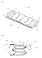
- FIGS. 4 to 6 are typical views illustrating a series of processes for assembling an exemplary cell unit.
- the metal housings 200 protect the battery cells 100a and 100b, which have low mechanical strength, and restrain the change in repetitive expansion and contraction during charge and discharge of the battery cells 100a and 100b, thereby preventing sealing portions of the battery cells 100a and 100b from being separated from each other.
- the metal housings 200 include a left housing part 211 and a right housing part 212. The metal housings 200 may be coupled to each other without using an additional fixing member.
- FIG. 5 is a sectional view of the metal housings 200 with a partially enlarged view of the metal housings 200.
- the metal housings 200 are configured to have a male and female coupling structure 221 and 222 in which the metal housing parts 211 and 212 are engaged with each other by elastic coupling when the metal housing parts 211 and 212 are pressed in which in a state in which the metal housing parts 211 and 212 are in contact with each other so that the metal housing parts 211 and 212 face each other. Consequently, it is possible to achieve strong mechanical coupling between the metal housings 200 without using an additional coupling member or an additional assembly process to assemble the metal housings 200. Such a simple coupling method is preferably applicable to mass production.
- FIG. 6 is a perspective view illustrating a cell unit according to an embodiment of the present invention.
- a cell unit 300 is configured so that the outside of a battery cell stack 100 is covered by a pair of metal housings 200 to reinforce mechanical properties of battery cells.
- Cathode terminals 121 and the anode terminals 120 of the battery cells are connected in parallel to each other by welding. To this end, the cathode terminals 121 and the anode terminals 120 of the battery cells are bent in a step shape.
- the metal housings 200 are formed of high-strength metal sheets which are coupled to each other so as to cover the outside of the battery cell stack excluding the electrode terminals of the battery cells.
- the metal housings 200 are provided at the left and right sides thereof with step parts 240, by which a module is easily fixed.
- the metal housing 200 are provided at the upper and lower ends thereof with step parts 250 to perform the same function.
- the metal housings 200 are provided at the upper and lower ends thereof with longitudinal fixing parts 260, by which the module is easily mounted.
- a plurality of linear protrusions, arranged at intervals in the lateral direction, is formed at the outsides of the metal housings 200.
- Projections 231 and 232 which are formed in opposite shapes, are formed at the upper end protrusion and the lower end protrusion, respectively.
- FIG. 7 is a typical view illustrating an exemplary battery module 400a in which cell units 300, 301 ... are stacked.
- the battery module 400a includes a total of 8 battery cells.
- the cell units 300, 301 ... are connected in series to each other in a state in which the cell units 300, 301 ... are stacked.
- two battery cells 100a and 100b are connected in parallel to each other.
- the parallel connection between the battery cells 100a and 100b is achieved by welding one end of an anode terminal 120a of the first battery cell 100a to one side of an anode terminal 120b of the second battery cell 100b in a tight contact fashion in a state in which the end of the anode terminal 120a of the first battery cell 100a is bent twice, as previously described.
- the series connection between the cell units 300 and 301 is achieved by bending one end of an anode terminal 120 (corresponding to the electrode terminal 120b of the second battery cell) of the first cell unit 300 and one end of a cathode terminal 130 (corresponding to an electrode terminal 130a of a third battery cell) of the second cell unit 301 into a ' ⁇ ' shape and welding overlapping portions of the first cell unit 300 and the second cell unit 301.
- connection between the electrode terminals 120a, 120b, 130a and 130b of the battery cells of the two cell units 300 and 301 is achieved by one to one welding at a single weld point 140, thereby maximally reducing internal resistance of the cell units.
- an external input and output terminal 410 is connected to the outermost first cell unit 300 at a position distant from the weld point between the electrode terminals 110a and 110b. Consequently, the electrode terminal 110 of the outermost first cell unit 300 is also connected to the external input and output terminal 410 by one to one welding at a single weld point.
- FIG. 8 is a typical view illustrating a battery module 400b in which cell units 310, 320 ... are connected to each other via bus bars 500.
- FIGS. 9 to 11 are typical views illustrating an exemplary bus bar.
- FIG. 12 is an exploded view of the battery module shown in FIG. 8 .
- the battery module 400b is configured so that the series connection between the cell units 310, 320 ... and the parallel connection between electrode terminals 120'a, 120'b, 130'a and 130'b are achieved using the bus bars 500 by one to one welding.
- a bus bar 500 is formed of a strip-shaped sheet.
- the bus bar 500 includes a middle series welding part 510 for series connection between the cell units 310 and 320 and a pair of side parallel welding parts 520 for parallel connection between the battery cells 100a and 100b.
- the side parallel welding parts 520 extend from opposite sides of the middle series welding part 510.
- the bus bar 500 is configured to have a structure in which the side parallel welding parts 520 are bent upward from the middle series welding part 510. Openings 530 are formed between the middle series welding part 510 and the side parallel welding parts 520 so that electrode terminals to be sequentially connected to each other are inserted through the openings 530.
- the anode terminal 120'b of the first cell unit 310 is welded to the bottom of the middle series welding part 510, and the cathode terminal 130'a of the second cell unit 320 is inserted through the opening 530 and is then welded to the top of the middle series welding part 510.
- bus bar configured to have the above structure, therefore, it is possible to insert the electrode terminals through the openings based on a desired structure, thereby achieving electrical connection and thus improving manufacturing process efficiency of the battery module.
- the battery module according to the present invention is configured so that the cell units, which minimizes the increase in weight and size of the battery module while effectively increasing low mechanical strength of the battery cells, are connected in series to each other, and the parallel connection between the electrode terminals of the battery cells of the cell units is achieved by one to one welding at a single weld point, thereby minimizing internal resistance and space restriction and thus improving manufacturing process efficiency of the battery module.
Landscapes
- Chemical & Material Sciences (AREA)
- Chemical Kinetics & Catalysis (AREA)
- Electrochemistry (AREA)
- General Chemical & Material Sciences (AREA)
- Inorganic Chemistry (AREA)
- Battery Mounting, Suspending (AREA)
- Connection Of Batteries Or Terminals (AREA)
- Secondary Cells (AREA)
- Sealing Battery Cases Or Jackets (AREA)
Applications Claiming Priority (2)
| Application Number | Priority Date | Filing Date | Title |
|---|---|---|---|
| KR1020100011754A KR101053208B1 (ko) | 2010-02-09 | 2010-02-09 | 용접 신뢰성이 향상된 전지모듈 및 이를 포함하는 중대형 전지팩 |
| PCT/KR2011/000394 WO2011099703A2 (fr) | 2010-02-09 | 2011-01-19 | Module accumulateur ayant une fiabilité de soudage améliorée, ainsi que batterie d'accumulateurs de dimension moyenne ou grande et comprenant celui-ci |
Publications (3)
| Publication Number | Publication Date |
|---|---|
| EP2535962A2 true EP2535962A2 (fr) | 2012-12-19 |
| EP2535962A4 EP2535962A4 (fr) | 2014-01-08 |
| EP2535962B1 EP2535962B1 (fr) | 2015-06-17 |
Family
ID=44368248
Family Applications (1)
| Application Number | Title | Priority Date | Filing Date |
|---|---|---|---|
| EP11742395.4A Active EP2535962B1 (fr) | 2010-02-09 | 2011-01-19 | Module accumulateur ayant une fiabilité de soudage améliorée, ainsi que batterie d'accumulateurs de dimension moyenne ou grande et comprenant celui-ci |
Country Status (6)
| Country | Link |
|---|---|
| US (1) | US8486557B2 (fr) |
| EP (1) | EP2535962B1 (fr) |
| JP (2) | JP5552546B2 (fr) |
| KR (1) | KR101053208B1 (fr) |
| CN (1) | CN102754240B (fr) |
| WO (1) | WO2011099703A2 (fr) |
Cited By (2)
| Publication number | Priority date | Publication date | Assignee | Title |
|---|---|---|---|---|
| CN106229452A (zh) * | 2016-08-31 | 2016-12-14 | 河南新太行电源股份有限公司 | 一种整体卡板电池弹性连接装置 |
| EP3561906A4 (fr) * | 2017-06-07 | 2020-03-04 | LG Chem, Ltd. | Module de batterie |
Families Citing this family (48)
| Publication number | Priority date | Publication date | Assignee | Title |
|---|---|---|---|---|
| KR101822879B1 (ko) | 2011-08-24 | 2018-01-30 | 에스케이이노베이션 주식회사 | 이차전지모듈 |
| JP6023416B2 (ja) * | 2011-10-19 | 2016-11-09 | 矢崎総業株式会社 | 電源装置 |
| KR101178152B1 (ko) * | 2012-02-23 | 2012-08-29 | 주식회사 엘지화학 | 신규한 구조의 전지팩 |
| KR102008740B1 (ko) * | 2012-10-05 | 2019-08-08 | 에스케이이노베이션 주식회사 | 전지팩 |
| KR102046122B1 (ko) * | 2013-05-21 | 2019-11-19 | 에스케이이노베이션 주식회사 | Pcb접속유닛 및 이를 이용한 전지모듈제작방법과 상기 방법에 의해 제작된 전지모듈 |
| JP5957651B2 (ja) * | 2013-06-07 | 2016-07-27 | パナソニックIpマネジメント株式会社 | 組電池 |
| KR101449307B1 (ko) | 2013-06-28 | 2014-10-08 | 현대자동차주식회사 | 배터리 안전장치 |
| CN104348204B (zh) * | 2013-08-05 | 2017-11-07 | 鸿富锦精密工业(深圳)有限公司 | 充放电系统 |
| EP3018733B1 (fr) | 2013-08-23 | 2017-06-14 | LG Chem, Ltd. | Module de batterie empilable ayant une structure de connexion pouvant être facilement modifiée |
| US9722229B2 (en) | 2013-09-20 | 2017-08-01 | Ford Global Technologies, Llc | Electric vehicle battery attachment assembly and method |
| KR101747397B1 (ko) * | 2013-09-25 | 2017-06-14 | 주식회사 엘지화학 | 댐핑 구조가 형성되어 있는 전극리드를 포함하는 전지모듈 |
| US10218027B2 (en) | 2013-11-11 | 2019-02-26 | A123 Systems, LLC | Vehicle starter battery |
| JP2015167103A (ja) * | 2014-03-04 | 2015-09-24 | 株式会社オートネットワーク技術研究所 | 蓄電モジュール |
| KR102381777B1 (ko) * | 2015-02-25 | 2022-04-01 | 삼성에스디아이 주식회사 | 배터리 팩 |
| JP6667167B2 (ja) | 2015-05-08 | 2020-03-18 | パナソニックIpマネジメント株式会社 | 組電池 |
| JP6685760B2 (ja) * | 2016-02-19 | 2020-04-22 | 株式会社Gsユアサ | 蓄電装置 |
| JP6575412B2 (ja) * | 2016-03-28 | 2019-09-18 | 株式会社デンソー | 組電池 |
| CN105789542B (zh) * | 2016-04-08 | 2018-09-25 | 深圳市国创动力系统有限公司 | 串并联的电池模组 |
| JP6752628B2 (ja) * | 2016-06-03 | 2020-09-09 | 太陽誘電株式会社 | 蓄電セル及び蓄電モジュール |
| JP6644650B2 (ja) * | 2016-06-29 | 2020-02-12 | 太陽誘電株式会社 | 蓄電セル、外装フィルム及び蓄電モジュール |
| JP6659483B2 (ja) * | 2016-07-05 | 2020-03-04 | 株式会社エンビジョンAescジャパン | 電極タブとバスバとの接合状態の検査方法 |
| JP6762156B2 (ja) * | 2016-07-15 | 2020-09-30 | 株式会社エンビジョンAescジャパン | 組電池及び組電池の製造方法 |
| US10632857B2 (en) | 2016-08-17 | 2020-04-28 | Shape Corp. | Battery support and protection structure for a vehicle |
| JP6835505B2 (ja) * | 2016-08-30 | 2021-02-24 | 太陽誘電株式会社 | 蓄電セル、外装フィルム及び蓄電モジュール |
| JP6620944B2 (ja) * | 2016-11-28 | 2019-12-18 | トヨタ自動車株式会社 | 直列接続用のラミネート型電池、及び組電池 |
| CN110383526A (zh) | 2017-01-04 | 2019-10-25 | 形状集团 | 节点模块化的车辆电池托盘结构 |
| KR102350769B1 (ko) * | 2017-03-06 | 2022-01-13 | 삼성에스디아이 주식회사 | 이차 전지 |
| US10886513B2 (en) | 2017-05-16 | 2021-01-05 | Shape Corp. | Vehicle battery tray having tub-based integration |
| US11211656B2 (en) | 2017-05-16 | 2021-12-28 | Shape Corp. | Vehicle battery tray with integrated battery retention and support feature |
| US10483510B2 (en) | 2017-05-16 | 2019-11-19 | Shape Corp. | Polarized battery tray for a vehicle |
| KR102209767B1 (ko) * | 2017-06-13 | 2021-01-28 | 주식회사 엘지화학 | 전극 리드와 버스바의 결합 구조가 개선된 배터리 모듈 |
| KR102187067B1 (ko) * | 2017-08-10 | 2020-12-04 | 주식회사 엘지화학 | 배터리 모듈 및 배터리 모듈의 제조 방법 |
| EP3681753A4 (fr) | 2017-09-13 | 2021-04-21 | Shape Corp. | Plateau de batterie de véhicule à paroi périphérique tubulaire |
| WO2019071013A1 (fr) | 2017-10-04 | 2019-04-11 | Shape Corp. | Ensemble fond de bac support de batterie pour véhicules électriques |
| CN109981047A (zh) * | 2017-12-27 | 2019-07-05 | 中国电子科技集团公司第十八研究所 | 一种π型互联导线结构 |
| JP6922750B2 (ja) * | 2018-01-12 | 2021-08-18 | トヨタ自動車株式会社 | 蓄電装置 |
| WO2019169080A1 (fr) | 2018-03-01 | 2019-09-06 | Shape Corp. | Système de refroidissement intégré à un bac de batterie de véhicule |
| US11688910B2 (en) | 2018-03-15 | 2023-06-27 | Shape Corp. | Vehicle battery tray having tub-based component |
| CN108987657B (zh) * | 2018-06-12 | 2024-03-19 | 福建云众动力科技有限公司 | 一种电池串并联镍带 |
| EP3588614A1 (fr) | 2018-06-21 | 2020-01-01 | Hilti Aktiengesellschaft | Cellule en sachet et empilement |
| US11437666B2 (en) * | 2019-07-31 | 2022-09-06 | Karma Automotive Llc | Battery module including side pressure plates and pouch cell modules |
| US11742552B1 (en) * | 2020-01-03 | 2023-08-29 | Wisk Aero Llc | Hybrid battery interconnects |
| WO2021217967A1 (fr) * | 2020-04-30 | 2021-11-04 | 昆山宝创新能源科技有限公司 | Module de batterie, bloc-batterie et véhicule |
| WO2021217970A1 (fr) * | 2020-04-30 | 2021-11-04 | 昆山宝创新能源科技有限公司 | Module de batterie, groupe de modules de batterie le comprenant et automobile |
| CN111477805A (zh) * | 2020-04-30 | 2020-07-31 | 昆山宝创新能源科技有限公司 | 折叠电池组和车辆 |
| CN111477797A (zh) * | 2020-04-30 | 2020-07-31 | 昆山宝创新能源科技有限公司 | 折叠电池组和车辆 |
| EP4280342A1 (fr) * | 2021-01-15 | 2023-11-22 | Envision AESC Japan Ltd. | Module de batterie et procédé de fabrication de module de batterie |
| DE102022204440A1 (de) | 2022-05-05 | 2023-11-23 | Volkswagen Aktiengesellschaft | Batteriezelle sowie Verfahren zur Herstellung einer solchen Batteriezelle |
Citations (2)
| Publication number | Priority date | Publication date | Assignee | Title |
|---|---|---|---|---|
| JP2004031193A (ja) * | 2002-06-27 | 2004-01-29 | Nissan Motor Co Ltd | 組電池 |
| EP2416431A2 (fr) * | 2009-04-01 | 2012-02-08 | LG Chem, Ltd. | Module de batterie à structure de conception flexible de module et de milieu pour ensemble batterie de grande taille qui en est équipé |
Family Cites Families (21)
| Publication number | Priority date | Publication date | Assignee | Title |
|---|---|---|---|---|
| JP4124972B2 (ja) | 2001-02-23 | 2008-07-23 | Necトーキン株式会社 | 積層型リチウムイオン電池 |
| JP3767531B2 (ja) * | 2002-08-01 | 2006-04-19 | 日産自動車株式会社 | 電池集合体 |
| JP2005222701A (ja) * | 2004-02-03 | 2005-08-18 | Shin Kobe Electric Mach Co Ltd | 組電池 |
| JP2005349449A (ja) * | 2004-06-11 | 2005-12-22 | Nissan Motor Co Ltd | 超音波接合方法およびその装置 |
| JP2006066083A (ja) * | 2004-08-24 | 2006-03-09 | Nissan Motor Co Ltd | 組電池 |
| JP2006172870A (ja) * | 2004-12-15 | 2006-06-29 | Toyota Motor Corp | 電池と組電池 |
| KR100905391B1 (ko) * | 2004-12-24 | 2009-06-30 | 주식회사 엘지화학 | 이차전지 모듈의 단자 연결부재 |
| JP2006221938A (ja) * | 2005-02-09 | 2006-08-24 | Toyota Motor Corp | フィルム外装型蓄電装置 |
| JP4829587B2 (ja) * | 2005-10-14 | 2011-12-07 | 日本電気株式会社 | 電気デバイス集合体及びその製造方法 |
| KR100936262B1 (ko) * | 2005-10-21 | 2010-01-12 | 주식회사 엘지화학 | 신규한 구조의 전기 접속용 버스 바 및 그것을 포함하고있는 전지모듈 |
| KR100719713B1 (ko) * | 2005-12-29 | 2007-05-17 | 삼성에스디아이 주식회사 | 리튬 이온 전지 |
| JP5154454B2 (ja) * | 2006-03-06 | 2013-02-27 | エルジー・ケム・リミテッド | 電池モジュール |
| JP5041460B2 (ja) | 2006-03-23 | 2012-10-03 | 本田技研工業株式会社 | 鉛蓄電池 |
| JP5050390B2 (ja) * | 2006-04-10 | 2012-10-17 | 日産自動車株式会社 | 組電池 |
| KR100895203B1 (ko) * | 2006-05-15 | 2009-05-06 | 주식회사 엘지화학 | 중대형 전지모듈 |
| CN200986939Y (zh) * | 2006-10-09 | 2007-12-05 | 东莞新能源电子科技有限公司 | 动力电池的组合装置 |
| KR101115382B1 (ko) * | 2007-07-23 | 2012-02-15 | 주식회사 엘지화학 | 직렬 연결 구조의 고출력 이차전지 |
| US20090159354A1 (en) * | 2007-12-25 | 2009-06-25 | Wenfeng Jiang | Battery system having interconnected battery packs each having multiple electrochemical storage cells |
| KR101136800B1 (ko) * | 2008-02-29 | 2012-04-19 | 주식회사 엘지화학 | 전지모듈의 제조방법 및 중대형 전지팩 |
| CN101714620A (zh) * | 2008-10-08 | 2010-05-26 | 比亚迪股份有限公司 | 电池组及连接电池组的方法 |
| CN101562263A (zh) * | 2009-05-26 | 2009-10-21 | 高宾 | 软包装锂电池组电芯连接方法 |
-
2010
- 2010-02-09 KR KR1020100011754A patent/KR101053208B1/ko active IP Right Grant
-
2011
- 2011-01-19 CN CN201180008853.4A patent/CN102754240B/zh active Active
- 2011-01-19 EP EP11742395.4A patent/EP2535962B1/fr active Active
- 2011-01-19 WO PCT/KR2011/000394 patent/WO2011099703A2/fr active Application Filing
- 2011-01-19 JP JP2012552790A patent/JP5552546B2/ja active Active
-
2012
- 2012-03-02 US US13/410,500 patent/US8486557B2/en active Active
-
2014
- 2014-04-07 JP JP2014078413A patent/JP5816323B2/ja active Active
Patent Citations (2)
| Publication number | Priority date | Publication date | Assignee | Title |
|---|---|---|---|---|
| JP2004031193A (ja) * | 2002-06-27 | 2004-01-29 | Nissan Motor Co Ltd | 組電池 |
| EP2416431A2 (fr) * | 2009-04-01 | 2012-02-08 | LG Chem, Ltd. | Module de batterie à structure de conception flexible de module et de milieu pour ensemble batterie de grande taille qui en est équipé |
Non-Patent Citations (1)
| Title |
|---|
| See also references of WO2011099703A2 * |
Cited By (3)
| Publication number | Priority date | Publication date | Assignee | Title |
|---|---|---|---|---|
| CN106229452A (zh) * | 2016-08-31 | 2016-12-14 | 河南新太行电源股份有限公司 | 一种整体卡板电池弹性连接装置 |
| EP3561906A4 (fr) * | 2017-06-07 | 2020-03-04 | LG Chem, Ltd. | Module de batterie |
| US11342632B2 (en) | 2017-06-07 | 2022-05-24 | Lg Energy Solution, Ltd. | Battery module |
Also Published As
| Publication number | Publication date |
|---|---|
| US20120183840A1 (en) | 2012-07-19 |
| WO2011099703A2 (fr) | 2011-08-18 |
| JP5816323B2 (ja) | 2015-11-18 |
| JP2013519214A (ja) | 2013-05-23 |
| CN102754240A (zh) | 2012-10-24 |
| EP2535962A4 (fr) | 2014-01-08 |
| EP2535962B1 (fr) | 2015-06-17 |
| JP2014132594A (ja) | 2014-07-17 |
| KR101053208B1 (ko) | 2011-08-01 |
| CN102754240B (zh) | 2015-07-22 |
| JP5552546B2 (ja) | 2014-07-16 |
| WO2011099703A3 (fr) | 2011-11-17 |
| US8486557B2 (en) | 2013-07-16 |
Similar Documents
| Publication | Publication Date | Title |
|---|---|---|
| EP2535962B1 (fr) | Module accumulateur ayant une fiabilité de soudage améliorée, ainsi que batterie d'accumulateurs de dimension moyenne ou grande et comprenant celui-ci | |
| US9741984B2 (en) | Battery module of novel structure and battery pack comprising the same | |
| US9768427B2 (en) | Battery module assembly of improved reliability and battery pack employed with the same | |
| EP2416431B1 (fr) | Module de batterie à structure de conception flexible de module et de milieu pour ensemble batterie de grande taille qui en est équipé | |
| US9269934B2 (en) | Battery module | |
| US9620826B2 (en) | Middle or large-sized battery module | |
| US9640792B2 (en) | Battery assembly having single electrode terminal connection part | |
| EP1994581B1 (fr) | Module de batterie de taille moyenne ou grande | |
| US20140127550A1 (en) | Battery module of improved reliability and battery pack employed with the same | |
| KR101326182B1 (ko) | 외장부재와 카트리지를 포함하는 단위모듈에 기반한 전지모듈 | |
| EP2595238A2 (fr) | Bloc-batterie à structure compacte | |
| KR101478704B1 (ko) | 신규한 구조의 전지모듈 및 이를 포함하는 전지팩 | |
| KR101305218B1 (ko) | 중공 구조의 고정부재와 결합 부재를 포함하는 전지모듈 및 이를 포함하는 전지팩 | |
| KR20140056835A (ko) | 전지모듈 및 이를 포함하는 전지팩 | |
| KR101305229B1 (ko) | 외장부재와 방열부재를 포함하는 단위모듈 및 이를 포함하는 전지모듈 |
Legal Events
| Date | Code | Title | Description |
|---|---|---|---|
| PUAI | Public reference made under article 153(3) epc to a published international application that has entered the european phase |
Free format text: ORIGINAL CODE: 0009012 |
|
| 17P | Request for examination filed |
Effective date: 20120807 |
|
| AK | Designated contracting states |
Kind code of ref document: A2 Designated state(s): AL AT BE BG CH CY CZ DE DK EE ES FI FR GB GR HR HU IE IS IT LI LT LU LV MC MK MT NL NO PL PT RO RS SE SI SK SM TR |
|
| DAX | Request for extension of the european patent (deleted) | ||
| A4 | Supplementary search report drawn up and despatched |
Effective date: 20131209 |
|
| RIC1 | Information provided on ipc code assigned before grant |
Ipc: H01M 2/20 20060101ALI20131203BHEP Ipc: H01M 10/02 20060101ALI20131203BHEP Ipc: H01M 2/10 20060101AFI20131203BHEP Ipc: B60L 11/18 20060101ALI20131203BHEP Ipc: H01M 2/22 20060101ALI20131203BHEP |
|
| GRAP | Despatch of communication of intention to grant a patent |
Free format text: ORIGINAL CODE: EPIDOSNIGR1 |
|
| INTG | Intention to grant announced |
Effective date: 20141110 |
|
| GRAP | Despatch of communication of intention to grant a patent |
Free format text: ORIGINAL CODE: EPIDOSNIGR1 |
|
| INTG | Intention to grant announced |
Effective date: 20150401 |
|
| GRAS | Grant fee paid |
Free format text: ORIGINAL CODE: EPIDOSNIGR3 |
|
| GRAA | (expected) grant |
Free format text: ORIGINAL CODE: 0009210 |
|
| AK | Designated contracting states |
Kind code of ref document: B1 Designated state(s): AL AT BE BG CH CY CZ DE DK EE ES FI FR GB GR HR HU IE IS IT LI LT LU LV MC MK MT NL NO PL PT RO RS SE SI SK SM TR |
|
| REG | Reference to a national code |
Ref country code: GB Ref legal event code: FG4D |
|
| REG | Reference to a national code |
Ref country code: CH Ref legal event code: EP |
|
| REG | Reference to a national code |
Ref country code: AT Ref legal event code: REF Ref document number: 732348 Country of ref document: AT Kind code of ref document: T Effective date: 20150715 |
|
| REG | Reference to a national code |
Ref country code: IE Ref legal event code: FG4D |
|
| REG | Reference to a national code |
Ref country code: DE Ref legal event code: R096 Ref document number: 602011017210 Country of ref document: DE |
|
| PG25 | Lapsed in a contracting state [announced via postgrant information from national office to epo] |
Ref country code: LT Free format text: LAPSE BECAUSE OF FAILURE TO SUBMIT A TRANSLATION OF THE DESCRIPTION OR TO PAY THE FEE WITHIN THE PRESCRIBED TIME-LIMIT Effective date: 20150617 Ref country code: HR Free format text: LAPSE BECAUSE OF FAILURE TO SUBMIT A TRANSLATION OF THE DESCRIPTION OR TO PAY THE FEE WITHIN THE PRESCRIBED TIME-LIMIT Effective date: 20150617 Ref country code: NO Free format text: LAPSE BECAUSE OF FAILURE TO SUBMIT A TRANSLATION OF THE DESCRIPTION OR TO PAY THE FEE WITHIN THE PRESCRIBED TIME-LIMIT Effective date: 20150917 Ref country code: FI Free format text: LAPSE BECAUSE OF FAILURE TO SUBMIT A TRANSLATION OF THE DESCRIPTION OR TO PAY THE FEE WITHIN THE PRESCRIBED TIME-LIMIT Effective date: 20150617 |
|
| REG | Reference to a national code |
Ref country code: AT Ref legal event code: MK05 Ref document number: 732348 Country of ref document: AT Kind code of ref document: T Effective date: 20150617 |
|
| REG | Reference to a national code |
Ref country code: LT Ref legal event code: MG4D Ref country code: NL Ref legal event code: MP Effective date: 20150617 |
|
| PG25 | Lapsed in a contracting state [announced via postgrant information from national office to epo] |
Ref country code: BG Free format text: LAPSE BECAUSE OF FAILURE TO SUBMIT A TRANSLATION OF THE DESCRIPTION OR TO PAY THE FEE WITHIN THE PRESCRIBED TIME-LIMIT Effective date: 20150917 Ref country code: GR Free format text: LAPSE BECAUSE OF FAILURE TO SUBMIT A TRANSLATION OF THE DESCRIPTION OR TO PAY THE FEE WITHIN THE PRESCRIBED TIME-LIMIT Effective date: 20150918 Ref country code: RS Free format text: LAPSE BECAUSE OF FAILURE TO SUBMIT A TRANSLATION OF THE DESCRIPTION OR TO PAY THE FEE WITHIN THE PRESCRIBED TIME-LIMIT Effective date: 20150617 Ref country code: LV Free format text: LAPSE BECAUSE OF FAILURE TO SUBMIT A TRANSLATION OF THE DESCRIPTION OR TO PAY THE FEE WITHIN THE PRESCRIBED TIME-LIMIT Effective date: 20150617 |
|
| REG | Reference to a national code |
Ref country code: FR Ref legal event code: PLFP Year of fee payment: 6 |
|
| PG25 | Lapsed in a contracting state [announced via postgrant information from national office to epo] |
Ref country code: EE Free format text: LAPSE BECAUSE OF FAILURE TO SUBMIT A TRANSLATION OF THE DESCRIPTION OR TO PAY THE FEE WITHIN THE PRESCRIBED TIME-LIMIT Effective date: 20150617 |
|
| PG25 | Lapsed in a contracting state [announced via postgrant information from national office to epo] |
Ref country code: PT Free format text: LAPSE BECAUSE OF FAILURE TO SUBMIT A TRANSLATION OF THE DESCRIPTION OR TO PAY THE FEE WITHIN THE PRESCRIBED TIME-LIMIT Effective date: 20151019 Ref country code: AT Free format text: LAPSE BECAUSE OF FAILURE TO SUBMIT A TRANSLATION OF THE DESCRIPTION OR TO PAY THE FEE WITHIN THE PRESCRIBED TIME-LIMIT Effective date: 20150617 Ref country code: RO Free format text: LAPSE BECAUSE OF NON-PAYMENT OF DUE FEES Effective date: 20150617 Ref country code: SK Free format text: LAPSE BECAUSE OF FAILURE TO SUBMIT A TRANSLATION OF THE DESCRIPTION OR TO PAY THE FEE WITHIN THE PRESCRIBED TIME-LIMIT Effective date: 20150617 Ref country code: CZ Free format text: LAPSE BECAUSE OF FAILURE TO SUBMIT A TRANSLATION OF THE DESCRIPTION OR TO PAY THE FEE WITHIN THE PRESCRIBED TIME-LIMIT Effective date: 20150617 Ref country code: IS Free format text: LAPSE BECAUSE OF FAILURE TO SUBMIT A TRANSLATION OF THE DESCRIPTION OR TO PAY THE FEE WITHIN THE PRESCRIBED TIME-LIMIT Effective date: 20151017 Ref country code: PL Free format text: LAPSE BECAUSE OF FAILURE TO SUBMIT A TRANSLATION OF THE DESCRIPTION OR TO PAY THE FEE WITHIN THE PRESCRIBED TIME-LIMIT Effective date: 20150617 Ref country code: ES Free format text: LAPSE BECAUSE OF FAILURE TO SUBMIT A TRANSLATION OF THE DESCRIPTION OR TO PAY THE FEE WITHIN THE PRESCRIBED TIME-LIMIT Effective date: 20150617 |
|
| REG | Reference to a national code |
Ref country code: DE Ref legal event code: R097 Ref document number: 602011017210 Country of ref document: DE |
|
| PLBE | No opposition filed within time limit |
Free format text: ORIGINAL CODE: 0009261 |
|
| STAA | Information on the status of an ep patent application or granted ep patent |
Free format text: STATUS: NO OPPOSITION FILED WITHIN TIME LIMIT |
|
| PG25 | Lapsed in a contracting state [announced via postgrant information from national office to epo] |
Ref country code: DK Free format text: LAPSE BECAUSE OF FAILURE TO SUBMIT A TRANSLATION OF THE DESCRIPTION OR TO PAY THE FEE WITHIN THE PRESCRIBED TIME-LIMIT Effective date: 20150617 Ref country code: IT Free format text: LAPSE BECAUSE OF FAILURE TO SUBMIT A TRANSLATION OF THE DESCRIPTION OR TO PAY THE FEE WITHIN THE PRESCRIBED TIME-LIMIT Effective date: 20150617 |
|
| 26N | No opposition filed |
Effective date: 20160318 |
|
| PG25 | Lapsed in a contracting state [announced via postgrant information from national office to epo] |
Ref country code: BE Free format text: LAPSE BECAUSE OF NON-PAYMENT OF DUE FEES Effective date: 20160131 |
|
| PG25 | Lapsed in a contracting state [announced via postgrant information from national office to epo] |
Ref country code: LU Free format text: LAPSE BECAUSE OF FAILURE TO SUBMIT A TRANSLATION OF THE DESCRIPTION OR TO PAY THE FEE WITHIN THE PRESCRIBED TIME-LIMIT Effective date: 20160119 Ref country code: SI Free format text: LAPSE BECAUSE OF FAILURE TO SUBMIT A TRANSLATION OF THE DESCRIPTION OR TO PAY THE FEE WITHIN THE PRESCRIBED TIME-LIMIT Effective date: 20150617 |
|
| REG | Reference to a national code |
Ref country code: CH Ref legal event code: PL |
|
| PG25 | Lapsed in a contracting state [announced via postgrant information from national office to epo] |
Ref country code: MC Free format text: LAPSE BECAUSE OF FAILURE TO SUBMIT A TRANSLATION OF THE DESCRIPTION OR TO PAY THE FEE WITHIN THE PRESCRIBED TIME-LIMIT Effective date: 20150617 |
|
| PG25 | Lapsed in a contracting state [announced via postgrant information from national office to epo] |
Ref country code: LI Free format text: LAPSE BECAUSE OF NON-PAYMENT OF DUE FEES Effective date: 20160131 Ref country code: CH Free format text: LAPSE BECAUSE OF NON-PAYMENT OF DUE FEES Effective date: 20160131 |
|
| REG | Reference to a national code |
Ref country code: IE Ref legal event code: MM4A |
|
| REG | Reference to a national code |
Ref country code: FR Ref legal event code: PLFP Year of fee payment: 7 |
|
| PG25 | Lapsed in a contracting state [announced via postgrant information from national office to epo] |
Ref country code: BE Free format text: LAPSE BECAUSE OF FAILURE TO SUBMIT A TRANSLATION OF THE DESCRIPTION OR TO PAY THE FEE WITHIN THE PRESCRIBED TIME-LIMIT Effective date: 20150617 |
|
| PG25 | Lapsed in a contracting state [announced via postgrant information from national office to epo] |
Ref country code: IE Free format text: LAPSE BECAUSE OF NON-PAYMENT OF DUE FEES Effective date: 20160119 |
|
| PG25 | Lapsed in a contracting state [announced via postgrant information from national office to epo] |
Ref country code: NL Free format text: LAPSE BECAUSE OF FAILURE TO SUBMIT A TRANSLATION OF THE DESCRIPTION OR TO PAY THE FEE WITHIN THE PRESCRIBED TIME-LIMIT Effective date: 20150617 Ref country code: SE Free format text: LAPSE BECAUSE OF FAILURE TO SUBMIT A TRANSLATION OF THE DESCRIPTION OR TO PAY THE FEE WITHIN THE PRESCRIBED TIME-LIMIT Effective date: 20150617 |
|
| PG25 | Lapsed in a contracting state [announced via postgrant information from national office to epo] |
Ref country code: MT Free format text: LAPSE BECAUSE OF FAILURE TO SUBMIT A TRANSLATION OF THE DESCRIPTION OR TO PAY THE FEE WITHIN THE PRESCRIBED TIME-LIMIT Effective date: 20150617 |
|
| REG | Reference to a national code |
Ref country code: FR Ref legal event code: PLFP Year of fee payment: 8 |
|
| PG25 | Lapsed in a contracting state [announced via postgrant information from national office to epo] |
Ref country code: CY Free format text: LAPSE BECAUSE OF FAILURE TO SUBMIT A TRANSLATION OF THE DESCRIPTION OR TO PAY THE FEE WITHIN THE PRESCRIBED TIME-LIMIT Effective date: 20150617 Ref country code: SM Free format text: LAPSE BECAUSE OF FAILURE TO SUBMIT A TRANSLATION OF THE DESCRIPTION OR TO PAY THE FEE WITHIN THE PRESCRIBED TIME-LIMIT Effective date: 20150617 Ref country code: HU Free format text: LAPSE BECAUSE OF FAILURE TO SUBMIT A TRANSLATION OF THE DESCRIPTION OR TO PAY THE FEE WITHIN THE PRESCRIBED TIME-LIMIT; INVALID AB INITIO Effective date: 20110119 |
|
| PG25 | Lapsed in a contracting state [announced via postgrant information from national office to epo] |
Ref country code: TR Free format text: LAPSE BECAUSE OF FAILURE TO SUBMIT A TRANSLATION OF THE DESCRIPTION OR TO PAY THE FEE WITHIN THE PRESCRIBED TIME-LIMIT Effective date: 20150617 Ref country code: MK Free format text: LAPSE BECAUSE OF FAILURE TO SUBMIT A TRANSLATION OF THE DESCRIPTION OR TO PAY THE FEE WITHIN THE PRESCRIBED TIME-LIMIT Effective date: 20150617 Ref country code: MT Free format text: LAPSE BECAUSE OF FAILURE TO SUBMIT A TRANSLATION OF THE DESCRIPTION OR TO PAY THE FEE WITHIN THE PRESCRIBED TIME-LIMIT Effective date: 20160131 |
|
| PG25 | Lapsed in a contracting state [announced via postgrant information from national office to epo] |
Ref country code: AL Free format text: LAPSE BECAUSE OF FAILURE TO SUBMIT A TRANSLATION OF THE DESCRIPTION OR TO PAY THE FEE WITHIN THE PRESCRIBED TIME-LIMIT Effective date: 20150617 |
|
| REG | Reference to a national code |
Ref country code: DE Ref legal event code: R079 Ref document number: 602011017210 Country of ref document: DE Free format text: PREVIOUS MAIN CLASS: H01M0002100000 Ipc: H01M0050200000 |
|
| REG | Reference to a national code |
Ref country code: DE Ref legal event code: R081 Ref document number: 602011017210 Country of ref document: DE Owner name: LG ENERGY SOLUTION LTD., KR Free format text: FORMER OWNER: LG CHEM. LTD., SEOUL/SOUL, KR Ref country code: DE Ref legal event code: R081 Ref document number: 602011017210 Country of ref document: DE Owner name: LG ENERGY SOLUTION, LTD., KR Free format text: FORMER OWNER: LG CHEM. LTD., SEOUL/SOUL, KR |
|
| P01 | Opt-out of the competence of the unified patent court (upc) registered |
Effective date: 20230408 |
|
| REG | Reference to a national code |
Ref country code: GB Ref legal event code: 732E Free format text: REGISTERED BETWEEN 20230824 AND 20230831 |
|
| REG | Reference to a national code |
Ref country code: DE Ref legal event code: R081 Ref document number: 602011017210 Country of ref document: DE Owner name: LG ENERGY SOLUTION, LTD., KR Free format text: FORMER OWNER: LG ENERGY SOLUTION LTD., SEOUL, KR |
|
| PGFP | Annual fee paid to national office [announced via postgrant information from national office to epo] |
Ref country code: GB Payment date: 20231220 Year of fee payment: 14 |
|
| PGFP | Annual fee paid to national office [announced via postgrant information from national office to epo] |
Ref country code: FR Payment date: 20231222 Year of fee payment: 14 |
|
| PGFP | Annual fee paid to national office [announced via postgrant information from national office to epo] |
Ref country code: DE Payment date: 20231220 Year of fee payment: 14 |