EP2535077B1 - Method of manufacturing a catheter for antimicrobial control and device for manufacturing thereof. - Google Patents
Method of manufacturing a catheter for antimicrobial control and device for manufacturing thereof. Download PDFInfo
- Publication number
- EP2535077B1 EP2535077B1 EP12172148.4A EP12172148A EP2535077B1 EP 2535077 B1 EP2535077 B1 EP 2535077B1 EP 12172148 A EP12172148 A EP 12172148A EP 2535077 B1 EP2535077 B1 EP 2535077B1
- Authority
- EP
- European Patent Office
- Prior art keywords
- conduit
- template
- guide tube
- texture
- features
- Prior art date
- Legal status (The legal status is an assumption and is not a legal conclusion. Google has not performed a legal analysis and makes no representation as to the accuracy of the status listed.)
- Not-in-force
Links
- 238000004519 manufacturing process Methods 0.000 title description 11
- 230000000845 anti-microbial effect Effects 0.000 title description 2
- 239000012530 fluid Substances 0.000 claims description 16
- 238000000034 method Methods 0.000 claims description 16
- 230000000737 periodic effect Effects 0.000 claims description 14
- 230000005855 radiation Effects 0.000 claims description 2
- -1 polydimethylsiloxane Polymers 0.000 description 21
- 229920000642 polymer Polymers 0.000 description 20
- 230000037361 pathway Effects 0.000 description 14
- 229920001971 elastomer Polymers 0.000 description 11
- 239000000806 elastomer Substances 0.000 description 11
- XLYOFNOQVPJJNP-UHFFFAOYSA-N water Substances O XLYOFNOQVPJJNP-UHFFFAOYSA-N 0.000 description 11
- 239000000203 mixture Substances 0.000 description 9
- 239000010410 layer Substances 0.000 description 7
- 239000004676 acrylonitrile butadiene styrene Substances 0.000 description 6
- 230000012010 growth Effects 0.000 description 6
- 229910052751 metal Inorganic materials 0.000 description 6
- 239000002184 metal Substances 0.000 description 6
- 229920000620 organic polymer Polymers 0.000 description 6
- 239000004417 polycarbonate Substances 0.000 description 6
- XECAHXYUAAWDEL-UHFFFAOYSA-N acrylonitrile butadiene styrene Chemical compound C=CC=C.C=CC#N.C=CC1=CC=CC=C1 XECAHXYUAAWDEL-UHFFFAOYSA-N 0.000 description 5
- 229920000122 acrylonitrile butadiene styrene Polymers 0.000 description 5
- 230000005684 electric field Effects 0.000 description 5
- 244000005700 microbiome Species 0.000 description 5
- 229920000515 polycarbonate Polymers 0.000 description 5
- 229920001169 thermoplastic Polymers 0.000 description 5
- 229920001187 thermosetting polymer Polymers 0.000 description 5
- 210000001519 tissue Anatomy 0.000 description 5
- 239000004677 Nylon Substances 0.000 description 4
- 229920001400 block copolymer Polymers 0.000 description 4
- 239000000919 ceramic Substances 0.000 description 4
- 238000010438 heat treatment Methods 0.000 description 4
- 229920001778 nylon Polymers 0.000 description 4
- 229920001296 polysiloxane Polymers 0.000 description 4
- 229920002943 EPDM rubber Polymers 0.000 description 3
- 239000004696 Poly ether ether ketone Substances 0.000 description 3
- 229920002313 fluoropolymer Polymers 0.000 description 3
- 239000004811 fluoropolymer Substances 0.000 description 3
- 239000007943 implant Substances 0.000 description 3
- 239000000463 material Substances 0.000 description 3
- 229920002492 poly(sulfone) Polymers 0.000 description 3
- 229920001707 polybutylene terephthalate Polymers 0.000 description 3
- 229920002530 polyetherether ketone Polymers 0.000 description 3
- 229920000139 polyethylene terephthalate Polymers 0.000 description 3
- 239000005020 polyethylene terephthalate Substances 0.000 description 3
- 229920006324 polyoxymethylene Polymers 0.000 description 3
- 239000000126 substance Substances 0.000 description 3
- 239000004634 thermosetting polymer Substances 0.000 description 3
- 229920002554 vinyl polymer Polymers 0.000 description 3
- XQUPVDVFXZDTLT-UHFFFAOYSA-N 1-[4-[[4-(2,5-dioxopyrrol-1-yl)phenyl]methyl]phenyl]pyrrole-2,5-dione Chemical compound O=C1C=CC(=O)N1C(C=C1)=CC=C1CC1=CC=C(N2C(C=CC2=O)=O)C=C1 XQUPVDVFXZDTLT-UHFFFAOYSA-N 0.000 description 2
- VSKJLJHPAFKHBX-UHFFFAOYSA-N 2-methylbuta-1,3-diene;styrene Chemical compound CC(=C)C=C.C=CC1=CC=CC=C1.C=CC1=CC=CC=C1 VSKJLJHPAFKHBX-UHFFFAOYSA-N 0.000 description 2
- LYCAIKOWRPUZTN-UHFFFAOYSA-N Ethylene glycol Chemical compound OCCO LYCAIKOWRPUZTN-UHFFFAOYSA-N 0.000 description 2
- 229920000459 Nitrile rubber Polymers 0.000 description 2
- 239000004952 Polyamide Substances 0.000 description 2
- 239000005062 Polybutadiene Substances 0.000 description 2
- 239000004698 Polyethylene Substances 0.000 description 2
- 239000004642 Polyimide Substances 0.000 description 2
- 239000004793 Polystyrene Substances 0.000 description 2
- KKEYFWRCBNTPAC-UHFFFAOYSA-N Terephthalic acid Chemical compound OC(=O)C1=CC=C(C(O)=O)C=C1 KKEYFWRCBNTPAC-UHFFFAOYSA-N 0.000 description 2
- FACXGONDLDSNOE-UHFFFAOYSA-N buta-1,3-diene;styrene Chemical compound C=CC=C.C=CC1=CC=CC=C1.C=CC1=CC=CC=C1 FACXGONDLDSNOE-UHFFFAOYSA-N 0.000 description 2
- WERYXYBDKMZEQL-UHFFFAOYSA-N butane-1,4-diol Chemical compound OCCCCO WERYXYBDKMZEQL-UHFFFAOYSA-N 0.000 description 2
- 239000011247 coating layer Substances 0.000 description 2
- 238000000576 coating method Methods 0.000 description 2
- 229920001577 copolymer Polymers 0.000 description 2
- 239000004205 dimethyl polysiloxane Substances 0.000 description 2
- 230000005670 electromagnetic radiation Effects 0.000 description 2
- 210000003709 heart valve Anatomy 0.000 description 2
- 229920003192 poly(bis maleimide) Polymers 0.000 description 2
- 229920001084 poly(chloroprene) Polymers 0.000 description 2
- 229920000435 poly(dimethylsiloxane) Polymers 0.000 description 2
- 229920002647 polyamide Polymers 0.000 description 2
- 229920002857 polybutadiene Polymers 0.000 description 2
- 229920000728 polyester Polymers 0.000 description 2
- 229920006393 polyether sulfone Polymers 0.000 description 2
- 229920001601 polyetherimide Polymers 0.000 description 2
- 229920000573 polyethylene Polymers 0.000 description 2
- 229920001721 polyimide Polymers 0.000 description 2
- 229920001955 polyphenylene ether Polymers 0.000 description 2
- 229920002223 polystyrene Polymers 0.000 description 2
- 229920005996 polystyrene-poly(ethylene-butylene)-polystyrene Polymers 0.000 description 2
- 229920001343 polytetrafluoroethylene Polymers 0.000 description 2
- 229920000915 polyvinyl chloride Polymers 0.000 description 2
- 238000005086 pumping Methods 0.000 description 2
- 239000007787 solid Substances 0.000 description 2
- 229920000468 styrene butadiene styrene block copolymer Polymers 0.000 description 2
- 229920002803 thermoplastic polyurethane Polymers 0.000 description 2
- 239000004416 thermosoftening plastic Substances 0.000 description 2
- 238000012876 topography Methods 0.000 description 2
- 230000007704 transition Effects 0.000 description 2
- JYEUMXHLPRZUAT-UHFFFAOYSA-N 1,2,3-triazine Chemical compound C1=CN=NN=C1 JYEUMXHLPRZUAT-UHFFFAOYSA-N 0.000 description 1
- KOMNUTZXSVSERR-UHFFFAOYSA-N 1,3,5-tris(prop-2-enyl)-1,3,5-triazinane-2,4,6-trione Chemical compound C=CCN1C(=O)N(CC=C)C(=O)N(CC=C)C1=O KOMNUTZXSVSERR-UHFFFAOYSA-N 0.000 description 1
- BJELTSYBAHKXRW-UHFFFAOYSA-N 2,4,6-triallyloxy-1,3,5-triazine Chemical compound C=CCOC1=NC(OCC=C)=NC(OCC=C)=N1 BJELTSYBAHKXRW-UHFFFAOYSA-N 0.000 description 1
- CMLFRMDBDNHMRA-UHFFFAOYSA-N 2h-1,2-benzoxazine Chemical compound C1=CC=C2C=CNOC2=C1 CMLFRMDBDNHMRA-UHFFFAOYSA-N 0.000 description 1
- PYSRRFNXTXNWCD-UHFFFAOYSA-N 3-(2-phenylethenyl)furan-2,5-dione Chemical compound O=C1OC(=O)C(C=CC=2C=CC=CC=2)=C1 PYSRRFNXTXNWCD-UHFFFAOYSA-N 0.000 description 1
- 241000251468 Actinopterygii Species 0.000 description 1
- 241000894006 Bacteria Species 0.000 description 1
- 206010053567 Coagulopathies Diseases 0.000 description 1
- RYGMFSIKBFXOCR-UHFFFAOYSA-N Copper Chemical compound [Cu] RYGMFSIKBFXOCR-UHFFFAOYSA-N 0.000 description 1
- 241000195493 Cryptophyta Species 0.000 description 1
- 239000004641 Diallyl-phthalate Substances 0.000 description 1
- 239000004593 Epoxy Substances 0.000 description 1
- 229920000181 Ethylene propylene rubber Polymers 0.000 description 1
- 239000004812 Fluorinated ethylene propylene Substances 0.000 description 1
- 244000043261 Hevea brasiliensis Species 0.000 description 1
- 229920000877 Melamine resin Polymers 0.000 description 1
- 239000002033 PVDF binder Substances 0.000 description 1
- 229920006169 Perfluoroelastomer Polymers 0.000 description 1
- 229930182556 Polyacetal Natural products 0.000 description 1
- 239000004962 Polyamide-imide Substances 0.000 description 1
- 229920002732 Polyanhydride Polymers 0.000 description 1
- 239000004695 Polyether sulfone Substances 0.000 description 1
- 239000004697 Polyetherimide Substances 0.000 description 1
- 239000004734 Polyphenylene sulfide Substances 0.000 description 1
- 229920002396 Polyurea Polymers 0.000 description 1
- FAPWRFPIFSIZLT-UHFFFAOYSA-M Sodium chloride Chemical compound [Na+].[Cl-] FAPWRFPIFSIZLT-UHFFFAOYSA-M 0.000 description 1
- 229920000147 Styrene maleic anhydride Polymers 0.000 description 1
- 239000004433 Thermoplastic polyurethane Substances 0.000 description 1
- 208000007536 Thrombosis Diseases 0.000 description 1
- 229920001807 Urea-formaldehyde Polymers 0.000 description 1
- DHKHKXVYLBGOIT-UHFFFAOYSA-N acetaldehyde Diethyl Acetal Natural products CCOC(C)OCC DHKHKXVYLBGOIT-UHFFFAOYSA-N 0.000 description 1
- 150000001241 acetals Chemical class 0.000 description 1
- 229920006397 acrylic thermoplastic Polymers 0.000 description 1
- 239000002390 adhesive tape Substances 0.000 description 1
- 229920000180 alkyd Polymers 0.000 description 1
- 239000000956 alloy Substances 0.000 description 1
- 229910045601 alloy Inorganic materials 0.000 description 1
- 230000004075 alteration Effects 0.000 description 1
- 229910052782 aluminium Inorganic materials 0.000 description 1
- XAGFODPZIPBFFR-UHFFFAOYSA-N aluminium Chemical compound [Al] XAGFODPZIPBFFR-UHFFFAOYSA-N 0.000 description 1
- 229920006125 amorphous polymer Polymers 0.000 description 1
- UMIVXZPTRXBADB-UHFFFAOYSA-N benzocyclobutene Chemical compound C1=CC=C2CCC2=C1 UMIVXZPTRXBADB-UHFFFAOYSA-N 0.000 description 1
- 230000035587 bioadhesion Effects 0.000 description 1
- QUDWYFHPNIMBFC-UHFFFAOYSA-N bis(prop-2-enyl) benzene-1,2-dicarboxylate Chemical compound C=CCOC(=O)C1=CC=CC=C1C(=O)OCC=C QUDWYFHPNIMBFC-UHFFFAOYSA-N 0.000 description 1
- 239000008280 blood Substances 0.000 description 1
- 210000004369 blood Anatomy 0.000 description 1
- 229920005549 butyl rubber Polymers 0.000 description 1
- 238000004113 cell culture Methods 0.000 description 1
- 230000008859 change Effects 0.000 description 1
- 230000035602 clotting Effects 0.000 description 1
- 239000011248 coating agent Substances 0.000 description 1
- 238000004891 communication Methods 0.000 description 1
- 238000010924 continuous production Methods 0.000 description 1
- 239000011889 copper foil Substances 0.000 description 1
- 238000004132 cross linking Methods 0.000 description 1
- 239000004643 cyanate ester Substances 0.000 description 1
- 239000000412 dendrimer Substances 0.000 description 1
- 229920000736 dendritic polymer Polymers 0.000 description 1
- 239000004053 dental implant Substances 0.000 description 1
- 238000000502 dialysis Methods 0.000 description 1
- 229920000359 diblock copolymer Polymers 0.000 description 1
- 238000005553 drilling Methods 0.000 description 1
- 239000000428 dust Substances 0.000 description 1
- 238000010894 electron beam technology Methods 0.000 description 1
- 229920005558 epichlorohydrin rubber Polymers 0.000 description 1
- HQQADJVZYDDRJT-UHFFFAOYSA-N ethene;prop-1-ene Chemical group C=C.CC=C HQQADJVZYDDRJT-UHFFFAOYSA-N 0.000 description 1
- 239000005038 ethylene vinyl acetate Substances 0.000 description 1
- 230000001815 facial effect Effects 0.000 description 1
- 238000001914 filtration Methods 0.000 description 1
- 229920001973 fluoroelastomer Polymers 0.000 description 1
- 229920005560 fluorosilicone rubber Polymers 0.000 description 1
- 239000011888 foil Substances 0.000 description 1
- IVJISJACKSSFGE-UHFFFAOYSA-N formaldehyde;1,3,5-triazine-2,4,6-triamine Chemical compound O=C.NC1=NC(N)=NC(N)=N1 IVJISJACKSSFGE-UHFFFAOYSA-N 0.000 description 1
- SLGWESQGEUXWJQ-UHFFFAOYSA-N formaldehyde;phenol Chemical compound O=C.OC1=CC=CC=C1 SLGWESQGEUXWJQ-UHFFFAOYSA-N 0.000 description 1
- XPFVYQJUAUNWIW-UHFFFAOYSA-N furfuryl alcohol Chemical class OCC1=CC=CO1 XPFVYQJUAUNWIW-UHFFFAOYSA-N 0.000 description 1
- 239000011521 glass Substances 0.000 description 1
- 229920005555 halobutyl Polymers 0.000 description 1
- 239000000017 hydrogel Substances 0.000 description 1
- WGCNASOHLSPBMP-UHFFFAOYSA-N hydroxyacetaldehyde Natural products OCC=O WGCNASOHLSPBMP-UHFFFAOYSA-N 0.000 description 1
- 229920002681 hypalon Polymers 0.000 description 1
- 208000015181 infectious disease Diseases 0.000 description 1
- 238000001990 intravenous administration Methods 0.000 description 1
- 239000012948 isocyanate Substances 0.000 description 1
- 150000002513 isocyanates Chemical class 0.000 description 1
- 238000002955 isolation Methods 0.000 description 1
- 238000002595 magnetic resonance imaging Methods 0.000 description 1
- 150000002739 metals Chemical class 0.000 description 1
- 210000004400 mucous membrane Anatomy 0.000 description 1
- 229920003052 natural elastomer Polymers 0.000 description 1
- 229920001194 natural rubber Polymers 0.000 description 1
- 150000002825 nitriles Chemical class 0.000 description 1
- 229920003986 novolac Polymers 0.000 description 1
- 239000003921 oil Substances 0.000 description 1
- 210000000056 organ Anatomy 0.000 description 1
- 239000003960 organic solvent Substances 0.000 description 1
- 230000005789 organism growth Effects 0.000 description 1
- 239000002245 particle Substances 0.000 description 1
- 229920009441 perflouroethylene propylene Polymers 0.000 description 1
- 229920013653 perfluoroalkoxyethylene Polymers 0.000 description 1
- 230000003239 periodontal effect Effects 0.000 description 1
- 229920001568 phenolic resin Polymers 0.000 description 1
- 229920002493 poly(chlorotrifluoroethylene) Polymers 0.000 description 1
- 229920003055 poly(ester-imide) Polymers 0.000 description 1
- 229920001643 poly(ether ketone) Polymers 0.000 description 1
- 229920001652 poly(etherketoneketone) Polymers 0.000 description 1
- 229920001200 poly(ethylene-vinyl acetate) Polymers 0.000 description 1
- 229920003229 poly(methyl methacrylate) Polymers 0.000 description 1
- 229920002627 poly(phosphazenes) Polymers 0.000 description 1
- 229920005559 polyacrylic rubber Polymers 0.000 description 1
- 229920002312 polyamide-imide Polymers 0.000 description 1
- 229920001230 polyarylate Polymers 0.000 description 1
- 229920002577 polybenzoxazole Polymers 0.000 description 1
- 229920001692 polycarbonate urethane Polymers 0.000 description 1
- 239000005023 polychlorotrifluoroethylene (PCTFE) polymer Substances 0.000 description 1
- 229920000867 polyelectrolyte Polymers 0.000 description 1
- 229920001195 polyisoprene Polymers 0.000 description 1
- ODGAOXROABLFNM-UHFFFAOYSA-N polynoxylin Chemical compound O=C.NC(N)=O ODGAOXROABLFNM-UHFFFAOYSA-N 0.000 description 1
- 229920000098 polyolefin Polymers 0.000 description 1
- 229920000069 polyphenylene sulfide Polymers 0.000 description 1
- 229920001709 polysilazane Polymers 0.000 description 1
- 229920001021 polysulfide Polymers 0.000 description 1
- 239000005077 polysulfide Substances 0.000 description 1
- 150000008117 polysulfides Polymers 0.000 description 1
- 239000004810 polytetrafluoroethylene Substances 0.000 description 1
- 229920002635 polyurethane Polymers 0.000 description 1
- 239000004814 polyurethane Substances 0.000 description 1
- 229920002451 polyvinyl alcohol Polymers 0.000 description 1
- 235000019422 polyvinyl alcohol Nutrition 0.000 description 1
- 239000004800 polyvinyl chloride Substances 0.000 description 1
- 229920001290 polyvinyl ester Polymers 0.000 description 1
- 229920001289 polyvinyl ether Polymers 0.000 description 1
- 229920001291 polyvinyl halide Polymers 0.000 description 1
- 229920006215 polyvinyl ketone Polymers 0.000 description 1
- 229920002981 polyvinylidene fluoride Polymers 0.000 description 1
- SCUZVMOVTVSBLE-UHFFFAOYSA-N prop-2-enenitrile;styrene Chemical compound C=CC#N.C=CC1=CC=CC=C1 SCUZVMOVTVSBLE-UHFFFAOYSA-N 0.000 description 1
- 229920003987 resole Polymers 0.000 description 1
- 229920006126 semicrystalline polymer Polymers 0.000 description 1
- 229920002379 silicone rubber Polymers 0.000 description 1
- 239000004945 silicone rubber Substances 0.000 description 1
- 239000011780 sodium chloride Substances 0.000 description 1
- 210000000130 stem cell Anatomy 0.000 description 1
- 229920000638 styrene acrylonitrile Polymers 0.000 description 1
- 229920003048 styrene butadiene rubber Polymers 0.000 description 1
- 238000006467 substitution reaction Methods 0.000 description 1
- 239000002344 surface layer Substances 0.000 description 1
- 238000001356 surgical procedure Methods 0.000 description 1
- 229920003051 synthetic elastomer Polymers 0.000 description 1
- ISXSCDLOGDJUNJ-UHFFFAOYSA-N tert-butyl prop-2-enoate Chemical compound CC(C)(C)OC(=O)C=C ISXSCDLOGDJUNJ-UHFFFAOYSA-N 0.000 description 1
- 229920002725 thermoplastic elastomer Polymers 0.000 description 1
- 150000003568 thioethers Chemical class 0.000 description 1
- 229920000428 triblock copolymer Polymers 0.000 description 1
- 229920006305 unsaturated polyester Polymers 0.000 description 1
Images


Classifications
-
- A—HUMAN NECESSITIES
- A61—MEDICAL OR VETERINARY SCIENCE; HYGIENE
- A61M—DEVICES FOR INTRODUCING MEDIA INTO, OR ONTO, THE BODY; DEVICES FOR TRANSDUCING BODY MEDIA OR FOR TAKING MEDIA FROM THE BODY; DEVICES FOR PRODUCING OR ENDING SLEEP OR STUPOR
- A61M25/00—Catheters; Hollow probes
- A61M25/01—Introducing, guiding, advancing, emplacing or holding catheters
- A61M25/09—Guide wires
-
- B—PERFORMING OPERATIONS; TRANSPORTING
- B29—WORKING OF PLASTICS; WORKING OF SUBSTANCES IN A PLASTIC STATE IN GENERAL
- B29C—SHAPING OR JOINING OF PLASTICS; SHAPING OF MATERIAL IN A PLASTIC STATE, NOT OTHERWISE PROVIDED FOR; AFTER-TREATMENT OF THE SHAPED PRODUCTS, e.g. REPAIRING
- B29C59/00—Surface shaping of articles, e.g. embossing; Apparatus therefor
- B29C59/02—Surface shaping of articles, e.g. embossing; Apparatus therefor by mechanical means, e.g. pressing
- B29C59/04—Surface shaping of articles, e.g. embossing; Apparatus therefor by mechanical means, e.g. pressing using rollers or endless belts
- B29C59/043—Surface shaping of articles, e.g. embossing; Apparatus therefor by mechanical means, e.g. pressing using rollers or endless belts for profiled articles
-
- A—HUMAN NECESSITIES
- A61—MEDICAL OR VETERINARY SCIENCE; HYGIENE
- A61M—DEVICES FOR INTRODUCING MEDIA INTO, OR ONTO, THE BODY; DEVICES FOR TRANSDUCING BODY MEDIA OR FOR TAKING MEDIA FROM THE BODY; DEVICES FOR PRODUCING OR ENDING SLEEP OR STUPOR
- A61M25/00—Catheters; Hollow probes
- A61M25/0009—Making of catheters or other medical or surgical tubes
- A61M25/0013—Weakening parts of a catheter tubing, e.g. by making cuts in the tube or reducing thickness of a layer at one point to adjust the flexibility
-
- A—HUMAN NECESSITIES
- A61—MEDICAL OR VETERINARY SCIENCE; HYGIENE
- A61M—DEVICES FOR INTRODUCING MEDIA INTO, OR ONTO, THE BODY; DEVICES FOR TRANSDUCING BODY MEDIA OR FOR TAKING MEDIA FROM THE BODY; DEVICES FOR PRODUCING OR ENDING SLEEP OR STUPOR
- A61M25/00—Catheters; Hollow probes
- A61M25/0021—Catheters; Hollow probes characterised by the form of the tubing
- A61M25/0023—Catheters; Hollow probes characterised by the form of the tubing by the form of the lumen, e.g. cross-section, variable diameter
-
- A—HUMAN NECESSITIES
- A61—MEDICAL OR VETERINARY SCIENCE; HYGIENE
- A61M—DEVICES FOR INTRODUCING MEDIA INTO, OR ONTO, THE BODY; DEVICES FOR TRANSDUCING BODY MEDIA OR FOR TAKING MEDIA FROM THE BODY; DEVICES FOR PRODUCING OR ENDING SLEEP OR STUPOR
- A61M25/00—Catheters; Hollow probes
- A61M25/01—Introducing, guiding, advancing, emplacing or holding catheters
-
- B—PERFORMING OPERATIONS; TRANSPORTING
- B29—WORKING OF PLASTICS; WORKING OF SUBSTANCES IN A PLASTIC STATE IN GENERAL
- B29C—SHAPING OR JOINING OF PLASTICS; SHAPING OF MATERIAL IN A PLASTIC STATE, NOT OTHERWISE PROVIDED FOR; AFTER-TREATMENT OF THE SHAPED PRODUCTS, e.g. REPAIRING
- B29C59/00—Surface shaping of articles, e.g. embossing; Apparatus therefor
- B29C59/02—Surface shaping of articles, e.g. embossing; Apparatus therefor by mechanical means, e.g. pressing
- B29C59/021—Surface shaping of articles, e.g. embossing; Apparatus therefor by mechanical means, e.g. pressing of profiled articles, e.g. hollow or tubular articles, beams
-
- B—PERFORMING OPERATIONS; TRANSPORTING
- B29—WORKING OF PLASTICS; WORKING OF SUBSTANCES IN A PLASTIC STATE IN GENERAL
- B29C—SHAPING OR JOINING OF PLASTICS; SHAPING OF MATERIAL IN A PLASTIC STATE, NOT OTHERWISE PROVIDED FOR; AFTER-TREATMENT OF THE SHAPED PRODUCTS, e.g. REPAIRING
- B29C59/00—Surface shaping of articles, e.g. embossing; Apparatus therefor
- B29C59/02—Surface shaping of articles, e.g. embossing; Apparatus therefor by mechanical means, e.g. pressing
- B29C59/022—Surface shaping of articles, e.g. embossing; Apparatus therefor by mechanical means, e.g. pressing characterised by the disposition or the configuration, e.g. dimensions, of the embossments or the shaping tools therefor
-
- A—HUMAN NECESSITIES
- A61—MEDICAL OR VETERINARY SCIENCE; HYGIENE
- A61M—DEVICES FOR INTRODUCING MEDIA INTO, OR ONTO, THE BODY; DEVICES FOR TRANSDUCING BODY MEDIA OR FOR TAKING MEDIA FROM THE BODY; DEVICES FOR PRODUCING OR ENDING SLEEP OR STUPOR
- A61M25/00—Catheters; Hollow probes
- A61M25/0043—Catheters; Hollow probes characterised by structural features
- A61M2025/006—Catheters; Hollow probes characterised by structural features having a special surface topography or special surface properties, e.g. roughened or knurled surface
-
- B—PERFORMING OPERATIONS; TRANSPORTING
- B29—WORKING OF PLASTICS; WORKING OF SUBSTANCES IN A PLASTIC STATE IN GENERAL
- B29C—SHAPING OR JOINING OF PLASTICS; SHAPING OF MATERIAL IN A PLASTIC STATE, NOT OTHERWISE PROVIDED FOR; AFTER-TREATMENT OF THE SHAPED PRODUCTS, e.g. REPAIRING
- B29C35/00—Heating, cooling or curing, e.g. crosslinking or vulcanising; Apparatus therefor
- B29C35/02—Heating or curing, e.g. crosslinking or vulcanizing during moulding, e.g. in a mould
- B29C35/08—Heating or curing, e.g. crosslinking or vulcanizing during moulding, e.g. in a mould by wave energy or particle radiation
- B29C35/0805—Heating or curing, e.g. crosslinking or vulcanizing during moulding, e.g. in a mould by wave energy or particle radiation using electromagnetic radiation
- B29C2035/0822—Heating or curing, e.g. crosslinking or vulcanizing during moulding, e.g. in a mould by wave energy or particle radiation using electromagnetic radiation using IR radiation
-
- B—PERFORMING OPERATIONS; TRANSPORTING
- B29—WORKING OF PLASTICS; WORKING OF SUBSTANCES IN A PLASTIC STATE IN GENERAL
- B29C—SHAPING OR JOINING OF PLASTICS; SHAPING OF MATERIAL IN A PLASTIC STATE, NOT OTHERWISE PROVIDED FOR; AFTER-TREATMENT OF THE SHAPED PRODUCTS, e.g. REPAIRING
- B29C35/00—Heating, cooling or curing, e.g. crosslinking or vulcanising; Apparatus therefor
- B29C35/02—Heating or curing, e.g. crosslinking or vulcanizing during moulding, e.g. in a mould
- B29C35/08—Heating or curing, e.g. crosslinking or vulcanizing during moulding, e.g. in a mould by wave energy or particle radiation
- B29C35/0805—Heating or curing, e.g. crosslinking or vulcanizing during moulding, e.g. in a mould by wave energy or particle radiation using electromagnetic radiation
- B29C2035/0827—Heating or curing, e.g. crosslinking or vulcanizing during moulding, e.g. in a mould by wave energy or particle radiation using electromagnetic radiation using UV radiation
-
- B—PERFORMING OPERATIONS; TRANSPORTING
- B29—WORKING OF PLASTICS; WORKING OF SUBSTANCES IN A PLASTIC STATE IN GENERAL
- B29C—SHAPING OR JOINING OF PLASTICS; SHAPING OF MATERIAL IN A PLASTIC STATE, NOT OTHERWISE PROVIDED FOR; AFTER-TREATMENT OF THE SHAPED PRODUCTS, e.g. REPAIRING
- B29C35/00—Heating, cooling or curing, e.g. crosslinking or vulcanising; Apparatus therefor
- B29C35/02—Heating or curing, e.g. crosslinking or vulcanizing during moulding, e.g. in a mould
- B29C35/08—Heating or curing, e.g. crosslinking or vulcanizing during moulding, e.g. in a mould by wave energy or particle radiation
- B29C35/0805—Heating or curing, e.g. crosslinking or vulcanizing during moulding, e.g. in a mould by wave energy or particle radiation using electromagnetic radiation
- B29C2035/0844—Heating or curing, e.g. crosslinking or vulcanizing during moulding, e.g. in a mould by wave energy or particle radiation using electromagnetic radiation using X-ray
-
- B—PERFORMING OPERATIONS; TRANSPORTING
- B29—WORKING OF PLASTICS; WORKING OF SUBSTANCES IN A PLASTIC STATE IN GENERAL
- B29C—SHAPING OR JOINING OF PLASTICS; SHAPING OF MATERIAL IN A PLASTIC STATE, NOT OTHERWISE PROVIDED FOR; AFTER-TREATMENT OF THE SHAPED PRODUCTS, e.g. REPAIRING
- B29C35/00—Heating, cooling or curing, e.g. crosslinking or vulcanising; Apparatus therefor
- B29C35/02—Heating or curing, e.g. crosslinking or vulcanizing during moulding, e.g. in a mould
- B29C35/08—Heating or curing, e.g. crosslinking or vulcanizing during moulding, e.g. in a mould by wave energy or particle radiation
- B29C35/0805—Heating or curing, e.g. crosslinking or vulcanizing during moulding, e.g. in a mould by wave energy or particle radiation using electromagnetic radiation
- B29C2035/0855—Heating or curing, e.g. crosslinking or vulcanizing during moulding, e.g. in a mould by wave energy or particle radiation using electromagnetic radiation using microwave
-
- B—PERFORMING OPERATIONS; TRANSPORTING
- B29—WORKING OF PLASTICS; WORKING OF SUBSTANCES IN A PLASTIC STATE IN GENERAL
- B29C—SHAPING OR JOINING OF PLASTICS; SHAPING OF MATERIAL IN A PLASTIC STATE, NOT OTHERWISE PROVIDED FOR; AFTER-TREATMENT OF THE SHAPED PRODUCTS, e.g. REPAIRING
- B29C35/00—Heating, cooling or curing, e.g. crosslinking or vulcanising; Apparatus therefor
- B29C35/02—Heating or curing, e.g. crosslinking or vulcanizing during moulding, e.g. in a mould
- B29C35/08—Heating or curing, e.g. crosslinking or vulcanizing during moulding, e.g. in a mould by wave energy or particle radiation
- B29C35/0805—Heating or curing, e.g. crosslinking or vulcanizing during moulding, e.g. in a mould by wave energy or particle radiation using electromagnetic radiation
- B29C2035/0861—Heating or curing, e.g. crosslinking or vulcanizing during moulding, e.g. in a mould by wave energy or particle radiation using electromagnetic radiation using radio frequency
-
- B—PERFORMING OPERATIONS; TRANSPORTING
- B29—WORKING OF PLASTICS; WORKING OF SUBSTANCES IN A PLASTIC STATE IN GENERAL
- B29C—SHAPING OR JOINING OF PLASTICS; SHAPING OF MATERIAL IN A PLASTIC STATE, NOT OTHERWISE PROVIDED FOR; AFTER-TREATMENT OF THE SHAPED PRODUCTS, e.g. REPAIRING
- B29C35/00—Heating, cooling or curing, e.g. crosslinking or vulcanising; Apparatus therefor
- B29C35/02—Heating or curing, e.g. crosslinking or vulcanizing during moulding, e.g. in a mould
- B29C35/08—Heating or curing, e.g. crosslinking or vulcanizing during moulding, e.g. in a mould by wave energy or particle radiation
- B29C35/0866—Heating or curing, e.g. crosslinking or vulcanizing during moulding, e.g. in a mould by wave energy or particle radiation using particle radiation
- B29C2035/0877—Heating or curing, e.g. crosslinking or vulcanizing during moulding, e.g. in a mould by wave energy or particle radiation using particle radiation using electron radiation, e.g. beta-rays
-
- B—PERFORMING OPERATIONS; TRANSPORTING
- B29—WORKING OF PLASTICS; WORKING OF SUBSTANCES IN A PLASTIC STATE IN GENERAL
- B29C—SHAPING OR JOINING OF PLASTICS; SHAPING OF MATERIAL IN A PLASTIC STATE, NOT OTHERWISE PROVIDED FOR; AFTER-TREATMENT OF THE SHAPED PRODUCTS, e.g. REPAIRING
- B29C35/00—Heating, cooling or curing, e.g. crosslinking or vulcanising; Apparatus therefor
- B29C35/02—Heating or curing, e.g. crosslinking or vulcanizing during moulding, e.g. in a mould
-
- B—PERFORMING OPERATIONS; TRANSPORTING
- B29—WORKING OF PLASTICS; WORKING OF SUBSTANCES IN A PLASTIC STATE IN GENERAL
- B29L—INDEXING SCHEME ASSOCIATED WITH SUBCLASS B29C, RELATING TO PARTICULAR ARTICLES
- B29L2023/00—Tubular articles
- B29L2023/003—Tubular articles having irregular or rough surfaces
-
- B—PERFORMING OPERATIONS; TRANSPORTING
- B29—WORKING OF PLASTICS; WORKING OF SUBSTANCES IN A PLASTIC STATE IN GENERAL
- B29L—INDEXING SCHEME ASSOCIATED WITH SUBCLASS B29C, RELATING TO PARTICULAR ARTICLES
- B29L2031/00—Other particular articles
- B29L2031/753—Medical equipment; Accessories therefor
- B29L2031/7542—Catheters
Definitions
- Disclosed herein is a catheter for antimicrobial control and methods of manufacturing thereof.
- Texturing Surfaces that have patterns and other forms of texturing (hereinafter “texturing”) can be advantageously used to minimize the adhesion of living organisms and other forms of non-living matter (e.g., ice, dust, dirt, and the like) to the surface.
- the texturing can have dimensions that are selected to specifically prevent the adhesion of specific living organisms or non-living matter on the surface, while at the same time encouraging the growth of other organisms or the adhesion of other types of non-living matter to the surface.
- the dimensions of the texturing may have to be in the nanometer or in the micrometer range, while for preventing the growth of certain other types of organisms, the dimensions of the texturing may have to be in the millimeter or centimeter range.
- the dimensions of the texturing may have to be in the nanometer or in the micrometer range, while for facilitating the growth of certain other types of organisms, the dimensions of the texturing may have to be in the millimeter or centimeter range.
- the invention is defined in the claims. Disclosed herein is a method comprising transporting a conduit and a template through a guide tube; the template being disposed on an outer surface of the conduit between the conduit and the guide tube; and transferring a texture from the template to the conduit as the conduit and the template are transported through the guide tube.
- an apparatus comprising a guide tube; the guide tube being operative to facilitate a transfer of a pattern from a template to a conduit; a first feed spool and a first take-up spool for feeding the conduit through the guide tube and for taking up the conduit after it has travelled through the guide tube respectively; and a second feed spool and a second take-up spool for feeding the template through the guide tube and for taking up the template after it has travelled through the guide tube respectively.
- a method comprising disposing a texture on a curved surface of a conduit; the texture comprising a plurality of patterns; each pattern being defined by a plurality of spaced apart features attached to or projected into the curved surface, the plurality of features each having at least one neighboring feature having a substantially different geometry, wherein an average spacing between adjacent spaced apart features is about 1 nanometer to about 1 millimeter in at least a portion of the curved surface, wherein the plurality of spaced apart features are represented by a periodic function; and disposing the conduit in a body of a living being.
- first, second, third etc. may be used herein to describe various elements, components, regions, layers and/or sections, these elements, components, regions, layers and/or sections should not be limited by these terms. These terms are only used to distinguish one element, component, region, layer or section from another element, component, region, layer or section. Thus, a first element, component, region, layer or section discussed below could be termed a second element, component, region, layer or section without departing from the teachings of the present invention.
- relative terms such as “lower” or “bottom” and “upper” or “top,” may be used herein to describe one element's relationship to another elements as illustrated in the Figures. It will be understood that relative terms are intended to encompass different orientations of the device in addition to the orientation depicted in the Figures. For example, if the device in one of the figures is turned over, elements described as being on the “lower” side of other elements would then be oriented on “upper” sides of the other elements. The exemplary term “lower,” can therefore, encompasses both an orientation of “lower” and “upper,” depending on the particular orientation of the figure.
- Exemplary embodiments are described herein with reference to cross section illustrations that are schematic illustrations of idealized embodiments. As such, variations from the shapes of the illustrations as a result, for example, of manufacturing techniques and/or tolerances, are to be expected. Thus, embodiments described herein should not be construed as limited to the particular shapes of regions as illustrated herein but are to include deviations in shapes that result, for example, from manufacturing. For example, a region illustrated or described as flat may, typically, have rough and/or nonlinear features. Moreover, sharp angles that are illustrated may be rounded. Thus, the regions illustrated in the figures are schematic in nature and their shapes are not intended to illustrate the precise shape of a region and are not intended to limit the scope of the present claims.
- a conduit that comprises a texture.
- the texture is disposed on a surface of the conduit.
- the surface of the conduit upon which the texture is disposed is generally an outer surface.
- the texture is disposed upon an outer surface of the conduit.
- the texture can be used to control bioadhesion on the conduit.
- the texturing can be used to minimize the adhesion of living or non-living matter, while in another embodiment, the texturing can be used to increase the adhesion of living or of non-living matter.
- the template is disposed between a guide tube and the conduit in a continuous process and transfers its pattern to the conduit upon the application of pressure to the conduit. During the travel of the conduit through the guide tube, pressure is applied to the template to transfer a texture contained on the template to the outer surface of the conduit.
- This method of manufacturing permits the texturing of large surfaces that have complex non-planar surfaces.
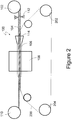
- an apparatus 100 for texturing the conduit comprises a first feed spool 102 for feeding the conduit 104 towards a guide tube 106 and an optional curing chamber 108.
- the conduit 104 is wound around a first take-up spool 110 after being fed through the guide tube 106 and the curing chamber 108.
- the apparatus 100 also comprises a second feed spool 202 and a second take-up spool 204 for feeding the template 206 and taking up the template 206 respectively.
- the template 206 contains an opposing image of the texture to be transmitted to the guide tube 106.
- An optional centering device 112 may be used to accurately feed the conduit to the guide tube 106.
- the conduit 104 is fed from the first feed spool 102 through the guide tube 106 and the curing chamber 108 and taken up by the first take-up spool 110.
- the template 206 is fed from the second feed spool 202 through the guide tube 106 and the curing chamber 108 to the second take-up spool 204.
- the template 206 is wrapped around a portion of the conduit 104.
- the template 206 is wrapped around the entire circumference of the conduit 104 that is present in the guide tube 106.
- a conical guide 114 in communication with the guide tube 106 facilitates the guiding of the conduit 104 into the guide tube 106.
- the conical guide 104 also facilitates the wrapping of the template 206 around the conduit 104.
- the pressure between the conduit 104 and the guide tube 106 causes the template to transfer an image of the desired texture to the conduit 104.
- the template is removed from the conduit 104 and rewound around the second take-up spool 204.
- the template 206 is a continuous belt that continuously travels around the second feed spool 202 and the second take-up spool 204 and contacts the conduit 104 during its travel through the guide tube 106.
- pressure may be applied to the conduit, the template and/or to the guide tube 106 to transfer the texture to the conduit.
- the pressure may be applied by pressurizing the conduit 104. Pressurizing the conduit 104 can be accomplished by increasing the fluid pressure within the conduit 104, forcing the conduit 104 radially outwards against the guide tube 106 thereby facilitating a transfer of the image from the template 206 to the conduit 104 as a result of the pressure.
- Fluids used within the conduit 104 may include air, water, magneto-rheo logical fluids and electro-rheological fluids.
- the use of magnetic field or an electrical field respectively may be used to increase the stiffness of the conduit 104, thereby increasing the pressure between the guide tube 106 and the conduit 104 resulting in a transfer of the image from the template 206 to the conduit 104.
- the pressure in the conduit may be about 0.01 to about 1.0 kilograms per square centimeter.
- a preferred pressure in the conduit is about 0.09 to about 0.45 kilograms per square centimeter.
- a solid mandrel (not shown) that has a higher stiffness than the guide tube may be disposed inside the conduit 104 during the travel of the conduit 104 through the guide tube 106.
- the use of a mandrel promotes an increase in pressure between the guide tube 106 and the conduit 104 resulting in a transfer of the image from the template 206 to the conduit 104.
- the mandrel may be hollow or have a solid core, but has a higher stiffness than the guide tube.
- the template 206 may be manufactured in the form of a balloon (i.e., a tube similar to a bicycle tube that can wrap itself around the conduit, but from which air cannot escape without intervention). During the passage through the guide tube 106, the pressure within the template 206 is increased resulting in a transfer of the image from the template 206 to the conduit 104. Fluids used within the template 206 may include air, water, magneto-rheological fluids and electro-rheological fluids.
- the guide tube 106 can be manufactured from a metal, a ceramic or a polymer.
- the guide tube is manufactured from a metal and has a low friction polymeric coating disposed on the inner surface thereof.
- low friction polymeric coatings include polymers that comprise polydimethylsiloxane and/or fluoropolymers.
- the guide tube is manufactured from a piezoelectric material that can have an electric field applied to it during the travel of the conduit and the template through it.
- Piezoelectric materials can change their dimensions upon the application of an electric field and conversely can generate an electric field when pressure is applied to the piezoelectric material.
- radial pressure can be applied by the guide tube to the template which then transfers an opposing image to the conduit.
- the guide tube 106 may be heated using resistive heating, electromagnetic radiation or a combination of resistive heating and electromagnetic radiation.
- the curing chamber 108 may be used to cure (crosslink) any reactive species on the conduit 104.
- the crosslinking can be accomplished using radiation (e.g., ultraviolet, infrared, microwave, radiofrequency, electron beam, xrays, or the like) or by heating. Curing can improve chemical resistance and/or thermal resistance of the conduit.
- the conduit 104 may comprise a metal, a ceramic an organic polymer, or a combination comprising at least one of a metal, a ceramic, or an organic polymer.
- the organic polymer may comprise a glassy polymer (i.e., a polymer that is below its glass temperature at the temperature of the human body), an elastomer (a polymer that is above its temperature at the temperature of the human body), an amorphous polymer or a semicrystalline polymer.
- Organic polymers may comprise thermosets, thermoplastics or a combination comprising at least one of a thermoset or a thermoplastic.
- the organic polymer may comprise a block copolymer, a diblock copolymer, a star block copolymer, a triblock copolymer, a dendrimer, an ionic copolymer, a polyelectrolyte, or the like.
- thermoplastic polymers are polyacetals, polyolefins, polyacrylics, polycarbonates, polystyrenes, polyesters, polyamides, polyamideimides, polyarylates, polyarylsulfones, polyethersulfones, polyphenylene sulfides, polyvinyl chlorides, polysulfones, polyimides, polyetherimides, polytetrafluoroethylenes, polyetherketones, polyether etherketones, polyether ketone ketones, polybenzoxazoles, polyphthalides, polyacetals, polyanhydrides, polyvinyl ethers, polyvinyl thioethers, polyvinyl alcohols, polyvinyl ketones, polyvinyl halides, polyvinyl nitriles, polyvinyl esters, polysulfonates, polysulfides, polythioesters, polysulfones, polysulfonamides, polyureas, polyphospha
- thermosetting polymers suitable for use in the polymeric composition include epoxy polymers, unsaturated polyester polymers, polyimide polymers, bismaleimide polymers, bismaleimide triazine polymers, cyanate ester polymers, vinyl polymers, benzoxazine polymers, benzocyclobutene polymers, acrylics, alkyds, phenol-formaldehyde polymers, novolacs, resoles, melamine-formaldehyde polymers, urea-formaldehyde polymers, hydroxymethylfurans, isocyanates, diallyl phthalate, triallyl cyanurate, triallyl isocyanurate, unsaturated polyesterimides, or the like, or a combination comprising at least one of the foregoing thermosetting polymers.
- thermoplastic polymers examples include acrylonitrile-butadiene-styrene/nylon, polycarbonate/acrylonitrile-butadiene-styrene, acrylonitrile butadiene styrene/polyvinyl chloride, polyphenylene ether/polystyrene, polyphenylene ether/nylon, polysulfone/acrylonitrile-butadiene-styrene, polycarbonate/thermoplastic urethane, polycarbonate/polyethylene terephthalate, polycarbonate/polybutylene terephthalate, thermoplastic elastomer alloys, nylon/elastomers, polyester/elastomers, polyethylene terephthalate/polybutylene terephthalate, acetal/elastomer, styrene-maleicanhydride/acrylonitrile-butadiene-styrene, polyether etherketone/polyethersulf
- thermoplastic polymer comprises polysiloxane or a fluoropolymer.
- thermosetting polymer comprises polysiloxane or a fluoropolymer.
- the conduit it is desirable for the conduit to be manufactured from an elastomer.
- suitable elastomers are polydimethylsiloxane, polybutadiene, polyisoprene, styrene-butadiene-styrene (SBS), styrene-isoprene-styrene (SIS), styrene-ethylene/butylene-styrene (S-EB-S) block copolymers, thermoplastic polyurethanes, copolyester-ethers (block copolymers derived from terephthalic acid, polytetramethylene glycol, and 1,4-butanediol), natural rubber, synthetic polyisoprene, butyl rubber, halogenated butyl rubbers, polybutadiene, styrene-butadiene rubber, nitrile rubber, hydrogenated nitrile rubbers, chloroprene rubber, polychloroprene,
- the texture comprises a plurality of patterns.
- the pattern generally has some features that are of the order of a few nanometers to several hundreds of millimeters in size.
- Each pattern is defined by a plurality of spaced apart features attached to or projected into the curved surface.
- the plurality of features on the surface each has at least one neighboring feature that has a substantially different geometry or a substantially different size.
- the average spacing between adjacent features on the surface is between about 1 nanometer to about 1 millimeter in at least a portion of the curved surface.
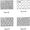
- the plurality of spaced apart features when viewed in a first direction, are represented by a periodic function. In another embodiment, the plurality of spaced apart features form a pattern. Each pattern is separated from a neighboring pattern by a pathway that has a periodicity to it. The periodicity of this pathway may be sinusoidal. Examples of the texture are shown in the Figures 3 , 4A, 4B, 4C and 4D .
- the conduit can comprise a pattern that comprises a plurality of spaced features.
- the spaced features are arranged in a plurality of groupings.
- the groupings of features comprise repeat units that can be repeated laterally and longitudinally across the surface.
- the spaced features within a grouping are spaced apart at an average distance of about 1 nanometer to about 500 micrometers.
- Each spaced feature has a surface that is substantially parallel to a surface on a neighboring feature.
- Each feature is separated from a neighboring feature and the groupings of features are arranged with respect to one another so as to define a tortuous pathway.
- the conduit comprises a plurality of spaced features.
- the features are arranged in a plurality of groupings such that the groupings of features comprise repeat units.
- the spaced features within a grouping are spaced apart at an average distance of about 1 nanometer to about 500 micrometers.
- the groupings of features are arranged with respect to one another so as to define a tortuous pathway where a tangent to the tortuous pathway intersects with a spaced feature.
- the spaced feature is different in geometry (shape or size) from each nearest neighbor and is not in contact with the nearest neighbor.
- the surface of the conduit has a topography that comprises a pattern defined by a plurality of spaced apart features attached to or projected into a base surface of the device (i.e., the base surface of the conduit).
- the plurality of features comprise at least one feature having a substantially different geometry, wherein neighboring patterns share a common feature, the plurality of spaced apart features having at least one dimension that is about 1 nanometer to about 1,000 micrometers.
- the neighboring spaced apart features can be spaced apart by a distance of about 5 nanometers to about 500 micrometers, specifically about 10 nanometers to about 100 micrometers, specifically about 1 micrometer to about 50 micrometers, and more specifically about 2 micrometers to about 25 micrometers.
- the surface after the texturing comprises a plurality of spaced features; the features being arranged in a plurality of groupings; the groupings of features comprising repeat units; the spaced features within a grouping being spaced apart at an average distance of about 1 nanometer to about 200 millimeters; the groupings of features being arranged with respect to one another so as to define a tortuous path.
- a tangent to the tortuous path intersects with at least one of the features.
- the tortuous path can be represented by a periodic function.
- the periodic function may be sinusoidal.
- the pathway between the features when viewed in a second direction, may be non-linear and non-sinusoidal. In other words, the pathway can be non-linear and aperiodic. In another embodiment, the pathway between the features may be linear but of a varying thickness.
- the plurality of spaced features may be projected outwards from a surface or projected into the surface. In one embodiment, the plurality of spaced features may have the same chemical composition as the surface. In another embodiment, the plurality of spaced features may have a different chemical composition from the surface.
- the surface of the conduit is monolithically integrated with the base of the conduit, wherein a composition of the conduit is the same as the composition of the surface of the conduit.
- the surface of the conduit comprises a coating layer disposed on the conduit.
- the composition of the coating layer is different from the composition of the conduit.
- the topography provides an average roughness factor (R) of from 2 to 50.
- the surface may comprise an elastomer that has an elastic modulus of about 10 kPa to about 10 MPa.
- the pattern is separated from a neighboring pattern by a tortuous pathway.
- the tortuous pathway may be represented by a periodic function.
- the periodic functions may be different for each tortuous pathway.
- the patterns can be separated from one another by tortuous pathways that can be represented by two or more periodic functions.
- the periodic functions may comprise a sinusoidal wave.
- the periodic function may comprise two or more sinusoidal waves.
- the respective periodic functions when a plurality of different tortuous pathways are represented by a plurality of periodic functions respectively, the respective periodic functions may be separated by a fixed phase difference. In yet another embodiment, when a plurality of different tortuous pathways are represented by a plurality of periodic functions respectively, the respective periodic functions may be separated by a variable phase difference.
- the plurality of spaced apart features have a substantially curved top surface that is concentric with the inner surface of the conduit.
- a multi-element plateau layer can be disposed on a portion of the surface of the conduit, wherein a spacing distance between elements of said surface layer provide a second feature spacing; the second feature spacing being substantially different when compared to the first feature spacing.
- each feature of a pattern has at least one neighboring feature that has a different geometry (e.g., size or shape).
- a feature of a pattern is a single element.
- Each feature of a pattern has at least 2, 3, 4, 5, or 6 neighboring features that have a different geometry from the feature.
- At least two identical features of the pattern have at least one neighboring feature that has a different geometry (e.g., size or shape).
- a feature of a pattern is a single element.
- two identical features of the pattern have at least 2, 3, 4, 5, or 6 neighboring features that have a different geometry from the identical features.
- three identical features of the pattern have at least 2, 3, 4, 5, or 6 neighboring features that have a different geometry from the identical features.
- each pattern has at least one or more neighboring patterns that have a different size or shape.
- a first pattern can have a second neighboring pattern that while comprising the same features as the first pattern can have a different shape from the first pattern.
- each pattern has at least two or more neighboring patterns that have a different size or shape.
- each pattern has at least three or more neighboring patterns that have a different size or shape.
- each pattern has at least four or more neighboring patterns that have a different size or shape.
- the template can be in the form of a film or in the form of a tube. It is desirable for the film or the tube to be flexible so that it can contact the conduit, be wrapped around it and be removed from it after transferring its texture to the conduit. It is desirable for the template to be wrapped completely around the conduit so that the texture can be transferred to the entire circumferential surface of the conduit. It is also desirable for the template to be reusable.
- a plurality of templates can be used to transfer the texture to the conduit.
- the lower half of the conduit can be textured by a first template while the upper half of the conduit can be textured by a second template.
- three or four different templates can contact different portions of the conduit and transfer the texture to the conduit.
- the template can comprise a polymer (e.g., those polymers listed above), or a metal or ceramic that is flexible enough to be wrapped around the conduit and unwrapped from the conduit upon completion of the transfer of the texture to the conduit.
- a polymer e.g., those polymers listed above
- An exemplary polymeric film is polycarbonate.
- Other polymers, blends of polymers, and copolymers listed above can also be used to manufacture the template.
- Metals such as aluminum foil, copper foil and the like can be used to manufacture the template.
- the template may also be in the form of a tube that can be filled with a fluid. It is desirable for the tube to be capable of being wrapped around the conduit and being removed from it after effecting the transfer of the pattern to the conduit.
- the tube can be inflated using a fluid such as, for example, air, water, volatile organic solvents, oils, and the like, or a combination comprising at least one of the foregoing fluids. Fluids that can be easily heated are desirable. Heated fluids can facilitate the heating of the template, which in turn can raise the temperature of the surface of the conduit above the softening point. The pressure and the temperature of the fluids can be controlled to vary the depth of the pattern in the surface of the conduit.
- the conduit with the texture disposed thereon can be used in a wide variety of applications.
- the conduit is generally used in applications where it is used under water.
- the texture can also be disposed on conduits used in water filtration used in fresh and saline water treatment facilities. For example, it can be used on the inner and outer surfaces of pipes and hoses used to transfer water or other fluids, filters, nozzles, valves, heaters, granular particles, and the like.
- the texture can also be disposed on surfaces that contact the mucous membranes of living beings.
- it can be used on all surfaces that are contacted by the human mouth especially those surfaces that contact the mouths of toddlers.
- surfaces that are contacted by the mouths of toddlers are frames and supporting rods of high chair trays, pacifiers, diaper changing pads, crib frames and rails, reusable and disposable water bottles, cups and mugs, coffee thermos, toys, blocks, coins, and the like.
- the texture can also be disposed on the surfaces of marine vessels and other devices that contact water.
- it can be used on intake and outlet pipes for industrial and power plants, drilling rigs for underwater surfaces, conduits used in fish tanks and aquariums, bilge tanks, water treatment plants and pumping station surfaces - any surface inside such as in a water treatment plant and pumping station where organism growth and colonization is an issue.
- the pattern can be disposed on the surfaces of bags used to grow algae, for example, it can be used on the surface of a bag used to grow any microorganism but prevent attachment of the microorganism onto the surface of bag (medical or marine - e.g., blood bags where it is desirable to deter organism attachment to bag).
- the surface texture or the size of the texture dimensions it can be used on the surface of a bag used to grow any microorganism and encourage attachment of the microorganism to surface of the bag (e.g., a stem cell culture where it is desirable to encourage growth and attachment to surface).
- a bag used to grow any microorganism and encourage attachment of the microorganism to surface of the bag (e.g., a stem cell culture where it is desirable to encourage growth and attachment to surface).
- the texture can also be used on the surfaces of body parts that are used in surgeries such as, for example, in a colostomy, and the like.
- the texture may also be used on the inner and outer surfaces of periodontal dressings; intravenous catheters and ports; foley catheters; surfaces in contact with tissues such as, for example, plates; adhesive tapes, patches, bandages, and the like; electronic leads; dental implants; orthodontia devices; iols (intraocular lenses); hydrogel films for tissue enhancement, skin grafting, isolation of bacteria or other microorganisms from tissues; heart-lung machine surfaces to reduce infection, clotting/thrombosis, enhance flow; tissue constructs for organ/tissue genesis; dialysis machine components, tubing and control panels; cochlear/otolaryngology implants and electronic devices; pace maker leads and body; fibrillator leads and body; heart valve flow surfaces and fixation surfaces; spinal implants; cranial/facial implants; biomedical instruments such as, for example, heart valves; scalp
Landscapes
- Health & Medical Sciences (AREA)
- Engineering & Computer Science (AREA)
- Life Sciences & Earth Sciences (AREA)
- Mechanical Engineering (AREA)
- Hematology (AREA)
- Anesthesiology (AREA)
- Biomedical Technology (AREA)
- Heart & Thoracic Surgery (AREA)
- Pulmonology (AREA)
- Animal Behavior & Ethology (AREA)
- General Health & Medical Sciences (AREA)
- Public Health (AREA)
- Veterinary Medicine (AREA)
- Biophysics (AREA)
- Materials For Medical Uses (AREA)
- Prostheses (AREA)
- Media Introduction/Drainage Providing Device (AREA)
Applications Claiming Priority (1)
| Application Number | Priority Date | Filing Date | Title |
|---|---|---|---|
| US13/161,137 US9937655B2 (en) | 2011-06-15 | 2011-06-15 | Method of manufacturing catheter for antimicrobial control |
Publications (3)
| Publication Number | Publication Date |
|---|---|
| EP2535077A2 EP2535077A2 (en) | 2012-12-19 |
| EP2535077A3 EP2535077A3 (en) | 2012-12-26 |
| EP2535077B1 true EP2535077B1 (en) | 2020-10-07 |
Family
ID=46465024
Family Applications (1)
| Application Number | Title | Priority Date | Filing Date |
|---|---|---|---|
| EP12172148.4A Not-in-force EP2535077B1 (en) | 2011-06-15 | 2012-06-15 | Method of manufacturing a catheter for antimicrobial control and device for manufacturing thereof. |
Country Status (6)
| Country | Link |
|---|---|
| US (3) | US9937655B2 (enExample) |
| EP (1) | EP2535077B1 (enExample) |
| JP (1) | JP6062165B2 (enExample) |
| KR (1) | KR102027585B1 (enExample) |
| AU (1) | AU2012203477B9 (enExample) |
| CA (1) | CA2779987C (enExample) |
Families Citing this family (15)
| Publication number | Priority date | Publication date | Assignee | Title |
|---|---|---|---|---|
| AU2009314119B2 (en) | 2008-11-11 | 2016-03-03 | University Of Florida Research Foundation, Inc. | Method of patterning a surface and articles comprising the same |
| US9937655B2 (en) | 2011-06-15 | 2018-04-10 | University Of Florida Research Foundation, Inc. | Method of manufacturing catheter for antimicrobial control |
| EP2893950A1 (en) * | 2014-01-14 | 2015-07-15 | Alvimedica Vascular Research B.V. | Catheter and method for manufacturing such catheter |
| MX2014004232A (es) * | 2014-04-08 | 2015-10-08 | Equipos Médicos Vizcarra S A | Sonda foley texturizada hidrofobica de baja adherencia microbiana. |
| BR112017002484A2 (pt) * | 2014-08-07 | 2017-12-05 | Sharklet Tech Inc | artigo, e artigo tubular |
| WO2017011050A2 (en) | 2015-04-23 | 2017-01-19 | University Of Florida Research Foundation, Inc. | Bilayered devices for enhanced healing |
| EP3328454A4 (en) * | 2015-07-30 | 2019-03-20 | Sharklet Technologies, Inc. | TEXTURED ARTICLES FOR IMPROVED CELL FORMATION AND METHOD FOR THE PRODUCTION THEREOF |
| US10500370B2 (en) * | 2015-09-02 | 2019-12-10 | Syracuse University | Antifouling urinary catheters with shape-memory topographic patterns |
| WO2018057582A1 (en) * | 2016-09-20 | 2018-03-29 | Sharklet Technologies, Inc. | Die for continuously manufacturing textured surfaces and methods of manufacture thereof |
| KR20190090782A (ko) * | 2016-09-20 | 2019-08-02 | 샤크렛 테크놀러지스, 아이엔씨. | 임프린팅 테이프, 이를 제조하는 방법 및 이를 포함하는 물품 |
| JP7099123B2 (ja) * | 2018-03-05 | 2022-07-12 | 大日本印刷株式会社 | 抗菌性および抗カビ性の少なくともいずれかを有する物品、ならびに抗菌性および抗カビ性の少なくともいずれかを有する物品製造用離型シート |
| US11717991B2 (en) | 2018-03-20 | 2023-08-08 | Sharklet Technologies, Inc. | Molds for manufacturing textured articles, methods of manufacturing thereof and articles manufactured therefrom |
| US12420456B2 (en) | 2018-03-20 | 2025-09-23 | Sharklet Technologies, Inc. | Molds for manufacturing textured articles, methods of manufacturing thereof and articles manufactured therefrom |
| JP2022513690A (ja) * | 2018-11-29 | 2022-02-09 | シャークレット テクノロジーズ インコーポレイテッド | 可溶性テンプレートを使用してテクスチャ加工表面を製造する方法 |
| KR20220024785A (ko) * | 2019-06-19 | 2022-03-03 | 샤크렛 테크놀러지스, 아이엔씨. | 텍스처링된 표면 배경을 갖는 물품을 형성하기 위한 방법 및 장치 |
Citations (3)
| Publication number | Priority date | Publication date | Assignee | Title |
|---|---|---|---|---|
| GB722591A (en) * | 1953-01-30 | 1955-01-26 | Telecommunications Sa | Improvements in or relating to the manufacture of tubular insulators for electric conductors |
| US3243850A (en) * | 1959-02-21 | 1966-04-05 | Fraenk Isolierrohr & Metall | Apparatus for the production of corrugated tubes |
| US3996323A (en) * | 1974-03-22 | 1976-12-07 | Wilhelm Hegler | Method of producing double-walled synthetic plastics tubes having an outer wall with annular or helical corrugations |
Family Cites Families (100)
| Publication number | Priority date | Publication date | Assignee | Title |
|---|---|---|---|---|
| DE403375C (de) | 1923-03-24 | 1924-09-30 | Georges Gustave Urbain Marie M | Verfahren zur Herstellung von farbigem Praegedruck auf Geweben, Leder oder anderen Stoffen |
| US3992162A (en) | 1955-06-09 | 1976-11-16 | Marc Wood International, Inc. | Sheet with alternate protrusions and recesses |
| US3351441A (en) | 1963-11-01 | 1967-11-07 | Wood Marc Sa | Shape, constitution and processes for manufacturing materials derived from developable chevroned configurations |
| GB1100423A (en) | 1964-02-24 | 1968-01-24 | American Can Co | Method and device for treating a smooth plastic sheet surface to reduce its coefficient of friction with respect to a smooth body surface |
| US3354022A (en) | 1964-03-31 | 1967-11-21 | Du Pont | Water-repellant surface |
| NL126099C (enExample) | 1964-11-02 | 1900-01-01 | ||
| ZA721376B (en) * | 1971-03-05 | 1972-11-29 | Amut Spa | Method and apparatus for shaping hollow extrudates of a plastics material |
| CA1026237A (en) | 1973-09-17 | 1978-02-14 | Kureha Kagaku Kogyo Kabushiki Kaisha | Key board switch |
| US3971084A (en) | 1974-03-07 | 1976-07-27 | Spier Martin I | Hull construction and method for forming same |
| JPS608986Y2 (ja) | 1976-02-28 | 1985-04-01 | 共同印刷株式会社 | 化粧板 |
| GB1536178A (en) | 1976-12-09 | 1978-12-20 | Boeing Co | Method and apparatus for printing indicia on a continuous elongate flexible three-dimensional member |
| US4101625A (en) | 1977-01-10 | 1978-07-18 | Fmc Corporation | Method for making corrugated molecularly oriented plastic strapping |
| DE2908487A1 (de) | 1979-03-05 | 1980-09-11 | Roehm Gmbh | Extrudierter hohlprofilstrang aus thermoplastischem kunststoff mit oberflaechenstruktur |
| US4297394A (en) | 1979-05-31 | 1981-10-27 | The United States Of America As Represented By The Secretary Of The Navy | Piezoelectric polymer antifouling coating and method of use and application |
| US4283461A (en) | 1979-05-31 | 1981-08-11 | The United States Of America As Represented By The Secretary Of The Navy | Piezoelectric polymer antifouling coating |
| US4284689A (en) | 1980-04-07 | 1981-08-18 | Bell Telephone Laboratories, Incorporated | Light-absorbing materials |
| US4640859A (en) | 1983-12-27 | 1987-02-03 | Minnesota Mining And Manufacturing Company | Inelastic, heat-elasticizable sheet material for diapers |
| US4637743A (en) | 1984-09-21 | 1987-01-20 | Aron Kerner | Matrix printer and inker for indefinite length articles |
| US4655986A (en) * | 1984-12-03 | 1987-04-07 | Dayco Products, Inc. | Blow molded tubing with special holes and method of making same |
| GB8717578D0 (en) | 1987-07-24 | 1987-09-03 | Telephone Cables Ltd | Communication cables |
| DE3801139C1 (enExample) | 1988-01-16 | 1989-03-09 | Roechling Haren Kg, 4472 Haren, De | |
| US4865603A (en) | 1988-02-04 | 1989-09-12 | Joint Medical Products Corporation | Metallic prosthetic devices having micro-textured outer surfaces |
| US5403680A (en) | 1988-08-30 | 1995-04-04 | Osaka Gas Company, Ltd. | Photolithographic and electron beam lithographic fabrication of micron and submicron three-dimensional arrays of electronically conductive polymers |
| US5008140A (en) | 1989-06-01 | 1991-04-16 | Schmertz John C | Biaxially corrugated flexible sheet material |
| US5028474A (en) | 1989-07-25 | 1991-07-02 | Czaplicki Ronald M | Cellular core structure providing gridlike bearing surfaces on opposing parallel planes of the formed core |
| US4988400A (en) * | 1989-10-04 | 1991-01-29 | Tremco Incorporated | Method and apparatus for treating the surface of an insulating strip |
| US5344691A (en) | 1990-03-30 | 1994-09-06 | Minnesota Mining And Manufacturing Company | Spatially modified elastic laminates |
| JPH0411620U (enExample) | 1990-05-21 | 1992-01-30 | ||
| US5330458A (en) | 1991-06-13 | 1994-07-19 | The Procter & Gamble Company | Absorbent article with elastic feature having a portion mechanically prestrained |
| FR2679723B1 (fr) | 1991-07-23 | 1994-12-30 | Siemens Automotive Sa | Procede de transmission de donnees numeriques emises sous forme de trames de signaux differentiels. |
| FR2683730B1 (fr) | 1991-11-19 | 1995-03-31 | Rossignol Sa | Ski, ou autre engin ou planche de glisse sur neige, a semelle striee. |
| USD436738S1 (en) | 1993-03-29 | 2001-01-30 | Fort James Corporation | Embossed paper product |
| JP2613844B2 (ja) * | 1993-12-03 | 1997-05-28 | 小松化成株式会社 | 繊維強化プラスチック製ロッドの連続引抜成形方法及びその装置 |
| BE1008153A7 (fr) | 1994-03-22 | 1996-01-30 | Damme Gilbert Van | Tete d'impression. |
| US6075585A (en) | 1994-04-12 | 2000-06-13 | The Board Of Trustees Of The Leland Stanford, Jr. University | Vibrating probe for a scanning probe microscope |
| PL178053B1 (pl) | 1994-07-29 | 2000-02-29 | Wilhelm Barthlott | Samooczyszczająca się powierzchnia elementów |
| US5645764A (en) | 1995-01-19 | 1997-07-08 | International Business Machines Corporation | Electrically conductive pressure sensitive adhesives |
| FR2735720B1 (fr) | 1995-06-26 | 1997-08-22 | Etiquetage Soc Fr | Dispositif d'impression par transfert, sur une bande, de charges initialement situees sur un film |
| US5762631A (en) | 1995-07-14 | 1998-06-09 | Localmed, Inc. | Method and system for reduced friction introduction of coaxial catheters |
| EP1007349B1 (en) | 1995-11-22 | 2004-09-29 | THE GOVERNMENT OF THE UNITED STATES OF AMERICA, as represented by THE SECRETARY OF THE NAVY | Patterned conducting polymer surfaces and process for preparing the same and devices containing the same |
| DE19613304A1 (de) | 1996-04-03 | 1997-10-09 | Ernst Koelle | Oberflächenstruktur für die Außenhaut bewegter oder ruhender Körper, die einem Strömungsmedium ausgesetzt sind |
| US5650214A (en) | 1996-05-31 | 1997-07-22 | The Procter & Gamble Company | Web materials exhibiting elastic-like behavior and soft, cloth-like texture |
| JPH10118188A (ja) | 1996-10-24 | 1998-05-12 | Terumo Corp | 体腔内挿入用医療用器具およびその製造方法 |
| DE19650439C1 (de) | 1996-12-05 | 1998-03-12 | Deutsch Zentr Luft & Raumfahrt | Oberfläche für eine von einer eine Strömungshauptrichtung aufweisenden Strömung turbulent umströmten Wand |
| US6197397B1 (en) | 1996-12-31 | 2001-03-06 | 3M Innovative Properties Company | Adhesives having a microreplicated topography and methods of making and using same |
| US5842937A (en) | 1997-10-22 | 1998-12-01 | Acushnet Company | Golf ball with surface texture defined by fractal geometry |
| WO1999033527A1 (en) | 1997-12-29 | 1999-07-08 | Dunlop-Maxfli Sports Corporation | Golf ball with secondary depressions |
| US6458447B1 (en) | 1998-04-16 | 2002-10-01 | The Proctor & Gamble Company | Extensible paper web and method of forming |
| USD430734S (en) | 1998-08-07 | 2000-09-12 | Fort James Corporation | Pattern for an embossed paper product |
| DE19840303A1 (de) | 1998-09-04 | 2000-03-09 | Brandhorst Ingo | Gezielte Erzeugung von Mikroturbolenzen zum Zwecke der Verminderung von Strömungsverlusten |
| DE19848943C2 (de) | 1998-10-23 | 2001-08-02 | Audi Ag | Verfahren zur Strukturierung der Innenfläche eines Kunststoffrohrs sowie eine Prägevorrichtung und ein Kunststoffrohrstück |
| US6616882B1 (en) | 1998-11-02 | 2003-09-09 | The Goodyear Tire & Rubber Company | Hose texturing apparatus and method |
| HUP0200452A2 (en) | 1999-03-25 | 2002-11-28 | Barthlott Wilhelm Dr | Method of producing self-cleaning detachable surfaces |
| US6394652B2 (en) | 1999-06-18 | 2002-05-28 | The Procter & Gamble Company | Flexible bags having stretch-to-fit conformity to closely accommodate contents in use |
| JP2001207123A (ja) | 1999-11-16 | 2001-07-31 | Sentan Kagaku Gijutsu Incubation Center:Kk | 高硬度高滑水性膜およびその製造方法 |
| US6231463B1 (en) | 1999-12-13 | 2001-05-15 | Spalding Worldwide Sports, Inc. | Golf balls having circular groups of tear-dropped dimples |
| USD459897S1 (en) | 2000-07-25 | 2002-07-09 | Fort James Corporation | Paper towel |
| AU2001284896A1 (en) | 2000-08-14 | 2002-02-25 | Surface Logix, Inc. | Deformable stamp for patterning three-dimensional surfaces |
| US6602225B2 (en) | 2001-02-28 | 2003-08-05 | Scimed Life Systems, Inc | Substantially circular catheter assembly |
| DE10118352A1 (de) | 2001-04-12 | 2002-10-17 | Creavis Tech & Innovation Gmbh | Selbstreinigende Oberflächen durch hydrophobe Strukturen und Verfahren zu deren Herstellung |
| US6569038B2 (en) | 2001-05-02 | 2003-05-27 | Acushnet Company | Golf ball dimples |
| JP2005537034A (ja) | 2001-06-23 | 2005-12-08 | シュペート ベルント | 表面特性を改善した本体 |
| DE20115718U1 (de) | 2001-09-25 | 2002-11-28 | Feintechnik R. Rittmeyer GmbH, 48155 Münster | Vorrichtung zum beidseitigen Bedrucken von Bandware wie Kabel, Schläuche, Litzen etc. mittels Heißprägeverfahren |
| DE10207194C1 (de) | 2002-02-21 | 2003-06-12 | Binder Gottlieb Gmbh & Co | Oberfläche |
| US6946170B2 (en) | 2002-02-21 | 2005-09-20 | Gottlieb Binder Gmbh & Company | Self-cleaning display device |
| US6686026B2 (en) | 2002-04-08 | 2004-02-03 | 3M Innovative Properties Company | Micro-channeled protective film |
| US6846172B2 (en) | 2002-06-07 | 2005-01-25 | The Procter & Gamble Company | Embossing apparatus |
| US20050008828A1 (en) | 2002-07-25 | 2005-01-13 | Trustees Of Stevens Institute Of Technology | Patterned polymer microgel and method of forming same |
| US20040086674A1 (en) | 2002-11-01 | 2004-05-06 | Holman Thomas J. | Laser sintering process and devices made therefrom |
| US20040191538A1 (en) | 2003-02-28 | 2004-09-30 | Xueying Huang | Nanometer-controlled polymeric thin films that resist adsorption of biological molecules and cells |
| EP1469198A1 (de) | 2003-04-17 | 2004-10-20 | Eugen Radtke | Auftriebsverbessernde Oberflächenstruktur für Windenergiekonverter |
| US20050119758A1 (en) | 2003-07-30 | 2005-06-02 | Bio-Lok International Inc. | Surgical implant for promotion of osseo-integration |
| US7117536B2 (en) | 2003-11-20 | 2006-10-10 | Lifetime Hoan Corporation | Silicone grabber |
| US20050119723A1 (en) | 2003-11-28 | 2005-06-02 | Medlogics Device Corporation | Medical device with porous surface containing bioerodable bioactive composites and related methods |
| USD518648S1 (en) | 2003-12-02 | 2006-04-11 | The Procter & Gamble Company | Surface pattern for embossed films |
| US9016221B2 (en) | 2004-02-17 | 2015-04-28 | University Of Florida Research Foundation, Inc. | Surface topographies for non-toxic bioadhesion control |
| US7143709B2 (en) | 2004-02-17 | 2006-12-05 | University Of Florida Research Foundation, Inc. | Surface topography for non-toxic bioadhesion control |
| US7650848B2 (en) * | 2004-02-17 | 2010-01-26 | University Of Florida Research Foundation, Inc. | Surface topographies for non-toxic bioadhesion control |
| US7117807B2 (en) | 2004-02-17 | 2006-10-10 | University Of Florida Research Foundation, Inc. | Dynamically modifiable polymer coatings and devices |
| US8075298B2 (en) * | 2004-09-08 | 2011-12-13 | Nil Technology Aps | Flexible nano-imprint stamp |
| EP1795363B1 (en) | 2004-09-10 | 2013-03-13 | Shuhou Co., Ltd. | Printing method on curved surface |
| US7303491B2 (en) | 2005-02-03 | 2007-12-04 | Acushnet Company | Golf ball with improved dimple pattern |
| DE102008015085A1 (de) | 2007-04-11 | 2008-10-16 | Eleonore Hanzel | Druckeinrichtung zum Drucken von Kennzeichnungen auf isolierte Runddrähte |
| JP5151496B2 (ja) | 2008-01-17 | 2013-02-27 | ソニー株式会社 | 画像形成装置及びそれに用いる改質シートカートリッジ |
| KR20110053333A (ko) | 2008-08-07 | 2011-05-20 | 유니-픽셀 디스플레이스, 인코포레이티드 | 표면상의 지문 현상을 줄이기 위한 미세구조 |
| AU2009314119B2 (en) | 2008-11-11 | 2016-03-03 | University Of Florida Research Foundation, Inc. | Method of patterning a surface and articles comprising the same |
| US9943402B2 (en) | 2008-11-20 | 2018-04-17 | Insight Innovations, Llc | Micropatterned intraocular implant |
| US8551386B2 (en) | 2009-08-03 | 2013-10-08 | S.D. Warren Company | Imparting texture to cured powder coatings |
| US9937655B2 (en) | 2011-06-15 | 2018-04-10 | University Of Florida Research Foundation, Inc. | Method of manufacturing catheter for antimicrobial control |
| US10221274B2 (en) | 2014-06-25 | 2019-03-05 | University Of Florida Research Foundation, Incorporated | Polyurethanes, articles comprising the same and methods of manufacture thereof |
| BR112017002484A2 (pt) | 2014-08-07 | 2017-12-05 | Sharklet Tech Inc | artigo, e artigo tubular |
| US9903792B2 (en) | 2014-10-30 | 2018-02-27 | Sharklet Technologies, Inc. | Ventilator-endotracheal tube-lung benchtop model |
| WO2017011050A2 (en) | 2015-04-23 | 2017-01-19 | University Of Florida Research Foundation, Inc. | Bilayered devices for enhanced healing |
| MX2017015526A (es) | 2015-06-03 | 2018-04-30 | Sharklet Tech Inc | Topografias de superficie para control de bioadhesión no tóxica. |
| EP3328454A4 (en) | 2015-07-30 | 2019-03-20 | Sharklet Technologies, Inc. | TEXTURED ARTICLES FOR IMPROVED CELL FORMATION AND METHOD FOR THE PRODUCTION THEREOF |
| CN109790404B (zh) | 2016-05-20 | 2021-12-14 | 佛罗里达大学研究基金会公司 | 新型raft聚合防污技术 |
| WO2018057582A1 (en) | 2016-09-20 | 2018-03-29 | Sharklet Technologies, Inc. | Die for continuously manufacturing textured surfaces and methods of manufacture thereof |
| KR20190090782A (ko) | 2016-09-20 | 2019-08-02 | 샤크렛 테크놀러지스, 아이엔씨. | 임프린팅 테이프, 이를 제조하는 방법 및 이를 포함하는 물품 |
| US10592018B2 (en) | 2017-03-14 | 2020-03-17 | Tactus Technology, Inc. | Elastomer tie layer and methods |
| US11717991B2 (en) | 2018-03-20 | 2023-08-08 | Sharklet Technologies, Inc. | Molds for manufacturing textured articles, methods of manufacturing thereof and articles manufactured therefrom |
-
2011
- 2011-06-15 US US13/161,137 patent/US9937655B2/en active Active
-
2012
- 2012-06-14 AU AU2012203477A patent/AU2012203477B9/en not_active Ceased
- 2012-06-15 KR KR1020120064447A patent/KR102027585B1/ko not_active Expired - Fee Related
- 2012-06-15 JP JP2012135807A patent/JP6062165B2/ja not_active Expired - Fee Related
- 2012-06-15 EP EP12172148.4A patent/EP2535077B1/en not_active Not-in-force
- 2012-06-15 CA CA2779987A patent/CA2779987C/en not_active Expired - Fee Related
-
2018
- 2018-02-27 US US15/906,497 patent/US10625465B2/en active Active
-
2020
- 2020-03-25 US US16/829,611 patent/US11491700B2/en active Active
Patent Citations (3)
| Publication number | Priority date | Publication date | Assignee | Title |
|---|---|---|---|---|
| GB722591A (en) * | 1953-01-30 | 1955-01-26 | Telecommunications Sa | Improvements in or relating to the manufacture of tubular insulators for electric conductors |
| US3243850A (en) * | 1959-02-21 | 1966-04-05 | Fraenk Isolierrohr & Metall | Apparatus for the production of corrugated tubes |
| US3996323A (en) * | 1974-03-22 | 1976-12-07 | Wilhelm Hegler | Method of producing double-walled synthetic plastics tubes having an outer wall with annular or helical corrugations |
Also Published As
| Publication number | Publication date |
|---|---|
| KR102027585B1 (ko) | 2019-11-04 |
| EP2535077A3 (en) | 2012-12-26 |
| US9937655B2 (en) | 2018-04-10 |
| US10625465B2 (en) | 2020-04-21 |
| AU2012203477B2 (en) | 2016-12-15 |
| US20120319325A1 (en) | 2012-12-20 |
| US20180186061A1 (en) | 2018-07-05 |
| AU2012203477A1 (en) | 2013-01-10 |
| CA2779987A1 (en) | 2012-12-15 |
| AU2012203477B9 (en) | 2017-02-02 |
| KR20120138709A (ko) | 2012-12-26 |
| CA2779987C (en) | 2019-08-20 |
| EP2535077A2 (en) | 2012-12-19 |
| JP6062165B2 (ja) | 2017-01-18 |
| JP2013046744A (ja) | 2013-03-07 |
| US20200238598A1 (en) | 2020-07-30 |
| US11491700B2 (en) | 2022-11-08 |
Similar Documents
| Publication | Publication Date | Title |
|---|---|---|
| US11491700B2 (en) | Method of manufacturing catheter for antimicrobial control | |
| US11383426B2 (en) | Method of patterning a surface and articles comprising the same | |
| CA2906920C (en) | Medical device curving apparatus, system, and method of use | |
| EP2632613B1 (en) | Engineered surfaces for reducing bacterial adhesion | |
| US11465332B2 (en) | Imprinting tape, method of manufacture thereof and articles comprising the same | |
| WO2013003373A1 (en) | Microstructured surfaces for reducing bacterial adhesion | |
| CN115551413A (zh) | 具有微结构化表面的医疗制品 | |
| JP7794635B2 (ja) | 生体組織に接触するための装置および方法 |
Legal Events
| Date | Code | Title | Description |
|---|---|---|---|
| PUAL | Search report despatched |
Free format text: ORIGINAL CODE: 0009013 |
|
| PUAI | Public reference made under article 153(3) epc to a published international application that has entered the european phase |
Free format text: ORIGINAL CODE: 0009012 |
|
| AK | Designated contracting states |
Kind code of ref document: A2 Designated state(s): AL AT BE BG CH CY CZ DE DK EE ES FI FR GB GR HR HU IE IS IT LI LT LU LV MC MK MT NL NO PL PT RO RS SE SI SK SM TR |
|
| AX | Request for extension of the european patent |
Extension state: BA ME |
|
| AK | Designated contracting states |
Kind code of ref document: A3 Designated state(s): AL AT BE BG CH CY CZ DE DK EE ES FI FR GB GR HR HU IE IS IT LI LT LU LV MC MK MT NL NO PL PT RO RS SE SI SK SM TR |
|
| AX | Request for extension of the european patent |
Extension state: BA ME |
|
| RIC1 | Information provided on ipc code assigned before grant |
Ipc: A61M 25/00 20060101AFI20121119BHEP Ipc: B29C 59/04 20060101ALI20121119BHEP Ipc: B29C 59/02 20060101ALI20121119BHEP |
|
| 17P | Request for examination filed |
Effective date: 20130620 |
|
| RBV | Designated contracting states (corrected) |
Designated state(s): AL AT BE BG CH CY CZ DE DK EE ES FI FR GB GR HR HU IE IS IT LI LT LU LV MC MK MT NL NO PL PT RO RS SE SI SK SM TR |
|
| 17Q | First examination report despatched |
Effective date: 20130725 |
|
| GRAP | Despatch of communication of intention to grant a patent |
Free format text: ORIGINAL CODE: EPIDOSNIGR1 |
|
| STAA | Information on the status of an ep patent application or granted ep patent |
Free format text: STATUS: GRANT OF PATENT IS INTENDED |
|
| INTG | Intention to grant announced |
Effective date: 20200420 |
|
| GRAS | Grant fee paid |
Free format text: ORIGINAL CODE: EPIDOSNIGR3 |
|
| GRAA | (expected) grant |
Free format text: ORIGINAL CODE: 0009210 |
|
| STAA | Information on the status of an ep patent application or granted ep patent |
Free format text: STATUS: THE PATENT HAS BEEN GRANTED |
|
| AK | Designated contracting states |
Kind code of ref document: B1 Designated state(s): AL AT BE BG CH CY CZ DE DK EE ES FI FR GB GR HR HU IE IS IT LI LT LU LV MC MK MT NL NO PL PT RO RS SE SI SK SM TR |
|
| REG | Reference to a national code |
Ref country code: GB Ref legal event code: FG4D |
|
| REG | Reference to a national code |
Ref country code: AT Ref legal event code: REF Ref document number: 1320496 Country of ref document: AT Kind code of ref document: T Effective date: 20201015 Ref country code: CH Ref legal event code: EP |
|
| REG | Reference to a national code |
Ref country code: IE Ref legal event code: FG4D |
|
| REG | Reference to a national code |
Ref country code: DE Ref legal event code: R096 Ref document number: 602012072637 Country of ref document: DE |
|
| REG | Reference to a national code |
Ref country code: NL Ref legal event code: MP Effective date: 20201007 |
|
| REG | Reference to a national code |
Ref country code: AT Ref legal event code: MK05 Ref document number: 1320496 Country of ref document: AT Kind code of ref document: T Effective date: 20201007 |
|
| PG25 | Lapsed in a contracting state [announced via postgrant information from national office to epo] |
Ref country code: GR Free format text: LAPSE BECAUSE OF FAILURE TO SUBMIT A TRANSLATION OF THE DESCRIPTION OR TO PAY THE FEE WITHIN THE PRESCRIBED TIME-LIMIT Effective date: 20210108 Ref country code: NO Free format text: LAPSE BECAUSE OF FAILURE TO SUBMIT A TRANSLATION OF THE DESCRIPTION OR TO PAY THE FEE WITHIN THE PRESCRIBED TIME-LIMIT Effective date: 20210107 Ref country code: PT Free format text: LAPSE BECAUSE OF FAILURE TO SUBMIT A TRANSLATION OF THE DESCRIPTION OR TO PAY THE FEE WITHIN THE PRESCRIBED TIME-LIMIT Effective date: 20210208 Ref country code: NL Free format text: LAPSE BECAUSE OF FAILURE TO SUBMIT A TRANSLATION OF THE DESCRIPTION OR TO PAY THE FEE WITHIN THE PRESCRIBED TIME-LIMIT Effective date: 20201007 Ref country code: RS Free format text: LAPSE BECAUSE OF FAILURE TO SUBMIT A TRANSLATION OF THE DESCRIPTION OR TO PAY THE FEE WITHIN THE PRESCRIBED TIME-LIMIT Effective date: 20201007 Ref country code: FI Free format text: LAPSE BECAUSE OF FAILURE TO SUBMIT A TRANSLATION OF THE DESCRIPTION OR TO PAY THE FEE WITHIN THE PRESCRIBED TIME-LIMIT Effective date: 20201007 |
|
| REG | Reference to a national code |
Ref country code: LT Ref legal event code: MG4D |
|
| PG25 | Lapsed in a contracting state [announced via postgrant information from national office to epo] |
Ref country code: SE Free format text: LAPSE BECAUSE OF FAILURE TO SUBMIT A TRANSLATION OF THE DESCRIPTION OR TO PAY THE FEE WITHIN THE PRESCRIBED TIME-LIMIT Effective date: 20201007 Ref country code: PL Free format text: LAPSE BECAUSE OF FAILURE TO SUBMIT A TRANSLATION OF THE DESCRIPTION OR TO PAY THE FEE WITHIN THE PRESCRIBED TIME-LIMIT Effective date: 20201007 Ref country code: LV Free format text: LAPSE BECAUSE OF FAILURE TO SUBMIT A TRANSLATION OF THE DESCRIPTION OR TO PAY THE FEE WITHIN THE PRESCRIBED TIME-LIMIT Effective date: 20201007 Ref country code: IS Free format text: LAPSE BECAUSE OF FAILURE TO SUBMIT A TRANSLATION OF THE DESCRIPTION OR TO PAY THE FEE WITHIN THE PRESCRIBED TIME-LIMIT Effective date: 20210207 Ref country code: ES Free format text: LAPSE BECAUSE OF FAILURE TO SUBMIT A TRANSLATION OF THE DESCRIPTION OR TO PAY THE FEE WITHIN THE PRESCRIBED TIME-LIMIT Effective date: 20201007 Ref country code: BG Free format text: LAPSE BECAUSE OF FAILURE TO SUBMIT A TRANSLATION OF THE DESCRIPTION OR TO PAY THE FEE WITHIN THE PRESCRIBED TIME-LIMIT Effective date: 20210107 Ref country code: AT Free format text: LAPSE BECAUSE OF FAILURE TO SUBMIT A TRANSLATION OF THE DESCRIPTION OR TO PAY THE FEE WITHIN THE PRESCRIBED TIME-LIMIT Effective date: 20201007 |
|
| PG25 | Lapsed in a contracting state [announced via postgrant information from national office to epo] |
Ref country code: HR Free format text: LAPSE BECAUSE OF FAILURE TO SUBMIT A TRANSLATION OF THE DESCRIPTION OR TO PAY THE FEE WITHIN THE PRESCRIBED TIME-LIMIT Effective date: 20201007 |
|
| REG | Reference to a national code |
Ref country code: DE Ref legal event code: R097 Ref document number: 602012072637 Country of ref document: DE |
|
| PG25 | Lapsed in a contracting state [announced via postgrant information from national office to epo] |
Ref country code: LT Free format text: LAPSE BECAUSE OF FAILURE TO SUBMIT A TRANSLATION OF THE DESCRIPTION OR TO PAY THE FEE WITHIN THE PRESCRIBED TIME-LIMIT Effective date: 20201007 Ref country code: SK Free format text: LAPSE BECAUSE OF FAILURE TO SUBMIT A TRANSLATION OF THE DESCRIPTION OR TO PAY THE FEE WITHIN THE PRESCRIBED TIME-LIMIT Effective date: 20201007 Ref country code: RO Free format text: LAPSE BECAUSE OF FAILURE TO SUBMIT A TRANSLATION OF THE DESCRIPTION OR TO PAY THE FEE WITHIN THE PRESCRIBED TIME-LIMIT Effective date: 20201007 Ref country code: SM Free format text: LAPSE BECAUSE OF FAILURE TO SUBMIT A TRANSLATION OF THE DESCRIPTION OR TO PAY THE FEE WITHIN THE PRESCRIBED TIME-LIMIT Effective date: 20201007 Ref country code: EE Free format text: LAPSE BECAUSE OF FAILURE TO SUBMIT A TRANSLATION OF THE DESCRIPTION OR TO PAY THE FEE WITHIN THE PRESCRIBED TIME-LIMIT Effective date: 20201007 Ref country code: CZ Free format text: LAPSE BECAUSE OF FAILURE TO SUBMIT A TRANSLATION OF THE DESCRIPTION OR TO PAY THE FEE WITHIN THE PRESCRIBED TIME-LIMIT Effective date: 20201007 |
|
| PLBE | No opposition filed within time limit |
Free format text: ORIGINAL CODE: 0009261 |
|
| STAA | Information on the status of an ep patent application or granted ep patent |
Free format text: STATUS: NO OPPOSITION FILED WITHIN TIME LIMIT |
|
| PG25 | Lapsed in a contracting state [announced via postgrant information from national office to epo] |
Ref country code: DK Free format text: LAPSE BECAUSE OF FAILURE TO SUBMIT A TRANSLATION OF THE DESCRIPTION OR TO PAY THE FEE WITHIN THE PRESCRIBED TIME-LIMIT Effective date: 20201007 |
|
| 26N | No opposition filed |
Effective date: 20210708 |
|
| PG25 | Lapsed in a contracting state [announced via postgrant information from national office to epo] |
Ref country code: IT Free format text: LAPSE BECAUSE OF FAILURE TO SUBMIT A TRANSLATION OF THE DESCRIPTION OR TO PAY THE FEE WITHIN THE PRESCRIBED TIME-LIMIT Effective date: 20201007 Ref country code: AL Free format text: LAPSE BECAUSE OF FAILURE TO SUBMIT A TRANSLATION OF THE DESCRIPTION OR TO PAY THE FEE WITHIN THE PRESCRIBED TIME-LIMIT Effective date: 20201007 |
|
| PG25 | Lapsed in a contracting state [announced via postgrant information from national office to epo] |
Ref country code: SI Free format text: LAPSE BECAUSE OF FAILURE TO SUBMIT A TRANSLATION OF THE DESCRIPTION OR TO PAY THE FEE WITHIN THE PRESCRIBED TIME-LIMIT Effective date: 20201007 |
|
| REG | Reference to a national code |
Ref country code: DE Ref legal event code: R119 Ref document number: 602012072637 Country of ref document: DE |
|
| PG25 | Lapsed in a contracting state [announced via postgrant information from national office to epo] |
Ref country code: MC Free format text: LAPSE BECAUSE OF FAILURE TO SUBMIT A TRANSLATION OF THE DESCRIPTION OR TO PAY THE FEE WITHIN THE PRESCRIBED TIME-LIMIT Effective date: 20201007 |
|
| REG | Reference to a national code |
Ref country code: CH Ref legal event code: PL |
|
| GBPC | Gb: european patent ceased through non-payment of renewal fee |
Effective date: 20210615 |
|
| REG | Reference to a national code |
Ref country code: BE Ref legal event code: MM Effective date: 20210630 |
|
| PG25 | Lapsed in a contracting state [announced via postgrant information from national office to epo] |
Ref country code: LU Free format text: LAPSE BECAUSE OF NON-PAYMENT OF DUE FEES Effective date: 20210615 |
|
| PG25 | Lapsed in a contracting state [announced via postgrant information from national office to epo] |
Ref country code: LI Free format text: LAPSE BECAUSE OF NON-PAYMENT OF DUE FEES Effective date: 20210630 Ref country code: IE Free format text: LAPSE BECAUSE OF NON-PAYMENT OF DUE FEES Effective date: 20210615 Ref country code: GB Free format text: LAPSE BECAUSE OF NON-PAYMENT OF DUE FEES Effective date: 20210615 Ref country code: DE Free format text: LAPSE BECAUSE OF NON-PAYMENT OF DUE FEES Effective date: 20220101 Ref country code: CH Free format text: LAPSE BECAUSE OF NON-PAYMENT OF DUE FEES Effective date: 20210630 |
|
| PG25 | Lapsed in a contracting state [announced via postgrant information from national office to epo] |
Ref country code: IS Free format text: LAPSE BECAUSE OF FAILURE TO SUBMIT A TRANSLATION OF THE DESCRIPTION OR TO PAY THE FEE WITHIN THE PRESCRIBED TIME-LIMIT Effective date: 20210207 Ref country code: FR Free format text: LAPSE BECAUSE OF NON-PAYMENT OF DUE FEES Effective date: 20210630 |
|
| PG25 | Lapsed in a contracting state [announced via postgrant information from national office to epo] |
Ref country code: BE Free format text: LAPSE BECAUSE OF NON-PAYMENT OF DUE FEES Effective date: 20210630 |
|
| PG25 | Lapsed in a contracting state [announced via postgrant information from national office to epo] |
Ref country code: HU Free format text: LAPSE BECAUSE OF FAILURE TO SUBMIT A TRANSLATION OF THE DESCRIPTION OR TO PAY THE FEE WITHIN THE PRESCRIBED TIME-LIMIT; INVALID AB INITIO Effective date: 20120615 Ref country code: CY Free format text: LAPSE BECAUSE OF FAILURE TO SUBMIT A TRANSLATION OF THE DESCRIPTION OR TO PAY THE FEE WITHIN THE PRESCRIBED TIME-LIMIT Effective date: 20201007 |
|
| PG25 | Lapsed in a contracting state [announced via postgrant information from national office to epo] |
Ref country code: MK Free format text: LAPSE BECAUSE OF FAILURE TO SUBMIT A TRANSLATION OF THE DESCRIPTION OR TO PAY THE FEE WITHIN THE PRESCRIBED TIME-LIMIT Effective date: 20201007 |
|
| PG25 | Lapsed in a contracting state [announced via postgrant information from national office to epo] |
Ref country code: TR Free format text: LAPSE BECAUSE OF FAILURE TO SUBMIT A TRANSLATION OF THE DESCRIPTION OR TO PAY THE FEE WITHIN THE PRESCRIBED TIME-LIMIT Effective date: 20201007 |
|
| PG25 | Lapsed in a contracting state [announced via postgrant information from national office to epo] |
Ref country code: MT Free format text: LAPSE BECAUSE OF FAILURE TO SUBMIT A TRANSLATION OF THE DESCRIPTION OR TO PAY THE FEE WITHIN THE PRESCRIBED TIME-LIMIT Effective date: 20201007 |