EP2535018A1 - Vorrichtung für temporären Embolieschutz - Google Patents
Vorrichtung für temporären Embolieschutz Download PDFInfo
- Publication number
- EP2535018A1 EP2535018A1 EP20120180196 EP12180196A EP2535018A1 EP 2535018 A1 EP2535018 A1 EP 2535018A1 EP 20120180196 EP20120180196 EP 20120180196 EP 12180196 A EP12180196 A EP 12180196A EP 2535018 A1 EP2535018 A1 EP 2535018A1
- Authority
- EP
- European Patent Office
- Prior art keywords
- unit
- aortic arch
- side branch
- protection
- aortic
- Prior art date
- Legal status (The legal status is an assumption and is not a legal conclusion. Google has not performed a legal analysis and makes no representation as to the accuracy of the status listed.)
- Granted
Links
- 230000003073 embolic effect Effects 0.000 title claims abstract description 123
- 210000002376 aorta thoracic Anatomy 0.000 claims abstract description 256
- 239000000463 material Substances 0.000 claims abstract description 104
- 230000017531 blood circulation Effects 0.000 claims abstract description 28
- 210000000709 aorta Anatomy 0.000 claims description 40
- 210000003270 subclavian artery Anatomy 0.000 claims description 28
- 210000001367 artery Anatomy 0.000 claims description 23
- 210000004369 blood Anatomy 0.000 claims description 22
- 239000008280 blood Substances 0.000 claims description 22
- 239000012530 fluid Substances 0.000 claims description 15
- 239000004744 fabric Substances 0.000 claims description 12
- 210000001168 carotid artery common Anatomy 0.000 claims description 10
- 230000002209 hydrophobic effect Effects 0.000 claims description 8
- 235000001674 Agaricus brunnescens Nutrition 0.000 claims description 6
- 239000013013 elastic material Substances 0.000 claims description 5
- 238000000034 method Methods 0.000 description 66
- 230000001681 protective effect Effects 0.000 description 54
- 210000001715 carotid artery Anatomy 0.000 description 21
- 239000010410 layer Substances 0.000 description 13
- 230000002669 organ and tissue protective effect Effects 0.000 description 11
- 239000002245 particle Substances 0.000 description 10
- 210000005259 peripheral blood Anatomy 0.000 description 9
- 239000011886 peripheral blood Substances 0.000 description 9
- 238000009954 braiding Methods 0.000 description 8
- 210000004556 brain Anatomy 0.000 description 8
- 230000002490 cerebral effect Effects 0.000 description 8
- 239000002184 metal Substances 0.000 description 7
- 238000007789 sealing Methods 0.000 description 6
- 230000006835 compression Effects 0.000 description 5
- 238000007906 compression Methods 0.000 description 5
- 230000010102 embolization Effects 0.000 description 5
- 230000002093 peripheral effect Effects 0.000 description 5
- 230000002792 vascular Effects 0.000 description 5
- 238000005452 bending Methods 0.000 description 4
- 230000008901 benefit Effects 0.000 description 4
- 238000007675 cardiac surgery Methods 0.000 description 4
- 238000000576 coating method Methods 0.000 description 4
- 206010008088 Cerebral artery embolism Diseases 0.000 description 3
- 229920000544 Gore-Tex Polymers 0.000 description 3
- 208000006011 Stroke Diseases 0.000 description 3
- 230000000747 cardiac effect Effects 0.000 description 3
- 239000003795 chemical substances by application Substances 0.000 description 3
- 239000011247 coating layer Substances 0.000 description 3
- 238000004891 communication Methods 0.000 description 3
- 230000006378 damage Effects 0.000 description 3
- 230000002526 effect on cardiovascular system Effects 0.000 description 3
- 230000006870 function Effects 0.000 description 3
- 201000010849 intracranial embolism Diseases 0.000 description 3
- HLXZNVUGXRDIFK-UHFFFAOYSA-N nickel titanium Chemical compound [Ti].[Ti].[Ti].[Ti].[Ti].[Ti].[Ti].[Ti].[Ti].[Ti].[Ti].[Ni].[Ni].[Ni].[Ni].[Ni].[Ni].[Ni].[Ni].[Ni].[Ni].[Ni].[Ni].[Ni].[Ni] HLXZNVUGXRDIFK-UHFFFAOYSA-N 0.000 description 3
- 229910001000 nickel titanium Inorganic materials 0.000 description 3
- 210000000056 organ Anatomy 0.000 description 3
- 230000035699 permeability Effects 0.000 description 3
- 229920001343 polytetrafluoroethylene Polymers 0.000 description 3
- 239000004810 polytetrafluoroethylene Substances 0.000 description 3
- 239000011148 porous material Substances 0.000 description 3
- 230000002265 prevention Effects 0.000 description 3
- 239000002344 surface layer Substances 0.000 description 3
- 208000007536 Thrombosis Diseases 0.000 description 2
- 238000004026 adhesive bonding Methods 0.000 description 2
- 230000036772 blood pressure Effects 0.000 description 2
- 208000029028 brain injury Diseases 0.000 description 2
- 230000004087 circulation Effects 0.000 description 2
- 230000000694 effects Effects 0.000 description 2
- 230000007831 electrophysiology Effects 0.000 description 2
- 238000002001 electrophysiology Methods 0.000 description 2
- 210000001105 femoral artery Anatomy 0.000 description 2
- 238000002594 fluoroscopy Methods 0.000 description 2
- 230000000642 iatrogenic effect Effects 0.000 description 2
- 238000002513 implantation Methods 0.000 description 2
- 208000014674 injury Diseases 0.000 description 2
- 238000004519 manufacturing process Methods 0.000 description 2
- 230000003446 memory effect Effects 0.000 description 2
- 238000002360 preparation method Methods 0.000 description 2
- 238000003825 pressing Methods 0.000 description 2
- 230000009993 protective function Effects 0.000 description 2
- 210000002321 radial artery Anatomy 0.000 description 2
- 230000008733 trauma Effects 0.000 description 2
- 238000011144 upstream manufacturing Methods 0.000 description 2
- 238000012800 visualization Methods 0.000 description 2
- 238000003466 welding Methods 0.000 description 2
- 206010003210 Arteriosclerosis Diseases 0.000 description 1
- 208000037260 Atherosclerotic Plaque Diseases 0.000 description 1
- 241000894006 Bacteria Species 0.000 description 1
- 208000022306 Cerebral injury Diseases 0.000 description 1
- 238000002679 ablation Methods 0.000 description 1
- 238000009825 accumulation Methods 0.000 description 1
- 239000000853 adhesive Substances 0.000 description 1
- 230000001070 adhesive effect Effects 0.000 description 1
- 210000003484 anatomy Anatomy 0.000 description 1
- 210000001765 aortic valve Anatomy 0.000 description 1
- 210000002302 brachial artery Anatomy 0.000 description 1
- 230000002612 cardiopulmonary effect Effects 0.000 description 1
- 238000013131 cardiovascular procedure Methods 0.000 description 1
- 210000000269 carotid artery external Anatomy 0.000 description 1
- 210000004004 carotid artery internal Anatomy 0.000 description 1
- 206010008118 cerebral infarction Diseases 0.000 description 1
- 208000026106 cerebrovascular disease Diseases 0.000 description 1
- 210000000038 chest Anatomy 0.000 description 1
- 239000011248 coating agent Substances 0.000 description 1
- 210000004351 coronary vessel Anatomy 0.000 description 1
- 230000007812 deficiency Effects 0.000 description 1
- 230000006735 deficit Effects 0.000 description 1
- 230000001419 dependent effect Effects 0.000 description 1
- 238000013461 design Methods 0.000 description 1
- 238000000605 extraction Methods 0.000 description 1
- 239000012634 fragment Substances 0.000 description 1
- 238000009998 heat setting Methods 0.000 description 1
- 230000001771 impaired effect Effects 0.000 description 1
- 238000003780 insertion Methods 0.000 description 1
- 230000037431 insertion Effects 0.000 description 1
- 208000037906 ischaemic injury Diseases 0.000 description 1
- 230000000302 ischemic effect Effects 0.000 description 1
- 150000002632 lipids Chemical class 0.000 description 1
- 230000007774 longterm Effects 0.000 description 1
- 210000001349 mammary artery Anatomy 0.000 description 1
- 238000005259 measurement Methods 0.000 description 1
- 230000007246 mechanism Effects 0.000 description 1
- 239000012528 membrane Substances 0.000 description 1
- 210000002418 meninge Anatomy 0.000 description 1
- 239000007769 metal material Substances 0.000 description 1
- 230000009461 neurocognitive dysfunction Effects 0.000 description 1
- 230000003557 neuropsychological effect Effects 0.000 description 1
- 229920000642 polymer Polymers 0.000 description 1
- -1 polytetrafluoroethylene Polymers 0.000 description 1
- 230000008569 process Effects 0.000 description 1
- 239000012858 resilient material Substances 0.000 description 1
- 229920000431 shape-memory polymer Polymers 0.000 description 1
- 239000002356 single layer Substances 0.000 description 1
- 239000007779 soft material Substances 0.000 description 1
- 210000000278 spinal cord Anatomy 0.000 description 1
- 229910001220 stainless steel Inorganic materials 0.000 description 1
- 239000010935 stainless steel Substances 0.000 description 1
- 238000001356 surgical procedure Methods 0.000 description 1
- 238000010408 sweeping Methods 0.000 description 1
- 230000008961 swelling Effects 0.000 description 1
- 230000009885 systemic effect Effects 0.000 description 1
- 210000000779 thoracic wall Anatomy 0.000 description 1
- 210000004881 tumor cell Anatomy 0.000 description 1
- 238000002604 ultrasonography Methods 0.000 description 1
- 210000002385 vertebral artery Anatomy 0.000 description 1
Images


Classifications
-
- A—HUMAN NECESSITIES
- A61—MEDICAL OR VETERINARY SCIENCE; HYGIENE
- A61F—FILTERS IMPLANTABLE INTO BLOOD VESSELS; PROSTHESES; DEVICES PROVIDING PATENCY TO, OR PREVENTING COLLAPSING OF, TUBULAR STRUCTURES OF THE BODY, e.g. STENTS; ORTHOPAEDIC, NURSING OR CONTRACEPTIVE DEVICES; FOMENTATION; TREATMENT OR PROTECTION OF EYES OR EARS; BANDAGES, DRESSINGS OR ABSORBENT PADS; FIRST-AID KITS
- A61F2/00—Filters implantable into blood vessels; Prostheses, i.e. artificial substitutes or replacements for parts of the body; Appliances for connecting them with the body; Devices providing patency to, or preventing collapsing of, tubular structures of the body, e.g. stents
- A61F2/02—Prostheses implantable into the body
-
- A—HUMAN NECESSITIES
- A61—MEDICAL OR VETERINARY SCIENCE; HYGIENE
- A61B—DIAGNOSIS; SURGERY; IDENTIFICATION
- A61B17/00—Surgical instruments, devices or methods, e.g. tourniquets
- A61B17/12—Surgical instruments, devices or methods, e.g. tourniquets for ligaturing or otherwise compressing tubular parts of the body, e.g. blood vessels, umbilical cord
- A61B17/12022—Occluding by internal devices, e.g. balloons or releasable wires
- A61B17/12099—Occluding by internal devices, e.g. balloons or releasable wires characterised by the location of the occluder
- A61B17/12109—Occluding by internal devices, e.g. balloons or releasable wires characterised by the location of the occluder in a blood vessel
-
- A—HUMAN NECESSITIES
- A61—MEDICAL OR VETERINARY SCIENCE; HYGIENE
- A61B—DIAGNOSIS; SURGERY; IDENTIFICATION
- A61B17/00—Surgical instruments, devices or methods, e.g. tourniquets
- A61B17/12—Surgical instruments, devices or methods, e.g. tourniquets for ligaturing or otherwise compressing tubular parts of the body, e.g. blood vessels, umbilical cord
- A61B17/12022—Occluding by internal devices, e.g. balloons or releasable wires
- A61B17/12027—Type of occlusion
- A61B17/12036—Type of occlusion partial occlusion
-
- A—HUMAN NECESSITIES
- A61—MEDICAL OR VETERINARY SCIENCE; HYGIENE
- A61B—DIAGNOSIS; SURGERY; IDENTIFICATION
- A61B17/00—Surgical instruments, devices or methods, e.g. tourniquets
- A61B17/12—Surgical instruments, devices or methods, e.g. tourniquets for ligaturing or otherwise compressing tubular parts of the body, e.g. blood vessels, umbilical cord
- A61B17/12022—Occluding by internal devices, e.g. balloons or releasable wires
- A61B17/12027—Type of occlusion
- A61B17/1204—Type of occlusion temporary occlusion
-
- A—HUMAN NECESSITIES
- A61—MEDICAL OR VETERINARY SCIENCE; HYGIENE
- A61B—DIAGNOSIS; SURGERY; IDENTIFICATION
- A61B17/00—Surgical instruments, devices or methods, e.g. tourniquets
- A61B17/12—Surgical instruments, devices or methods, e.g. tourniquets for ligaturing or otherwise compressing tubular parts of the body, e.g. blood vessels, umbilical cord
- A61B17/12022—Occluding by internal devices, e.g. balloons or releasable wires
- A61B17/12131—Occluding by internal devices, e.g. balloons or releasable wires characterised by the type of occluding device
- A61B17/12159—Solid plugs; being solid before insertion
-
- A—HUMAN NECESSITIES
- A61—MEDICAL OR VETERINARY SCIENCE; HYGIENE
- A61B—DIAGNOSIS; SURGERY; IDENTIFICATION
- A61B17/00—Surgical instruments, devices or methods, e.g. tourniquets
- A61B17/12—Surgical instruments, devices or methods, e.g. tourniquets for ligaturing or otherwise compressing tubular parts of the body, e.g. blood vessels, umbilical cord
- A61B17/12022—Occluding by internal devices, e.g. balloons or releasable wires
- A61B17/12131—Occluding by internal devices, e.g. balloons or releasable wires characterised by the type of occluding device
- A61B17/12168—Occluding by internal devices, e.g. balloons or releasable wires characterised by the type of occluding device having a mesh structure
- A61B17/12172—Occluding by internal devices, e.g. balloons or releasable wires characterised by the type of occluding device having a mesh structure having a pre-set deployed three-dimensional shape
-
- A—HUMAN NECESSITIES
- A61—MEDICAL OR VETERINARY SCIENCE; HYGIENE
- A61F—FILTERS IMPLANTABLE INTO BLOOD VESSELS; PROSTHESES; DEVICES PROVIDING PATENCY TO, OR PREVENTING COLLAPSING OF, TUBULAR STRUCTURES OF THE BODY, e.g. STENTS; ORTHOPAEDIC, NURSING OR CONTRACEPTIVE DEVICES; FOMENTATION; TREATMENT OR PROTECTION OF EYES OR EARS; BANDAGES, DRESSINGS OR ABSORBENT PADS; FIRST-AID KITS
- A61F2/00—Filters implantable into blood vessels; Prostheses, i.e. artificial substitutes or replacements for parts of the body; Appliances for connecting them with the body; Devices providing patency to, or preventing collapsing of, tubular structures of the body, e.g. stents
- A61F2/0063—Implantable repair or support meshes, e.g. hernia meshes
-
- A—HUMAN NECESSITIES
- A61—MEDICAL OR VETERINARY SCIENCE; HYGIENE
- A61F—FILTERS IMPLANTABLE INTO BLOOD VESSELS; PROSTHESES; DEVICES PROVIDING PATENCY TO, OR PREVENTING COLLAPSING OF, TUBULAR STRUCTURES OF THE BODY, e.g. STENTS; ORTHOPAEDIC, NURSING OR CONTRACEPTIVE DEVICES; FOMENTATION; TREATMENT OR PROTECTION OF EYES OR EARS; BANDAGES, DRESSINGS OR ABSORBENT PADS; FIRST-AID KITS
- A61F2/00—Filters implantable into blood vessels; Prostheses, i.e. artificial substitutes or replacements for parts of the body; Appliances for connecting them with the body; Devices providing patency to, or preventing collapsing of, tubular structures of the body, e.g. stents
- A61F2/01—Filters implantable into blood vessels
- A61F2/013—Distal protection devices, i.e. devices placed distally in combination with another endovascular procedure, e.g. angioplasty or stenting
-
- A—HUMAN NECESSITIES
- A61—MEDICAL OR VETERINARY SCIENCE; HYGIENE
- A61M—DEVICES FOR INTRODUCING MEDIA INTO, OR ONTO, THE BODY; DEVICES FOR TRANSDUCING BODY MEDIA OR FOR TAKING MEDIA FROM THE BODY; DEVICES FOR PRODUCING OR ENDING SLEEP OR STUPOR
- A61M29/00—Dilators with or without means for introducing media, e.g. remedies
-
- A—HUMAN NECESSITIES
- A61—MEDICAL OR VETERINARY SCIENCE; HYGIENE
- A61B—DIAGNOSIS; SURGERY; IDENTIFICATION
- A61B17/00—Surgical instruments, devices or methods, e.g. tourniquets
- A61B17/12—Surgical instruments, devices or methods, e.g. tourniquets for ligaturing or otherwise compressing tubular parts of the body, e.g. blood vessels, umbilical cord
- A61B17/12022—Occluding by internal devices, e.g. balloons or releasable wires
- A61B2017/1205—Introduction devices
-
- A—HUMAN NECESSITIES
- A61—MEDICAL OR VETERINARY SCIENCE; HYGIENE
- A61F—FILTERS IMPLANTABLE INTO BLOOD VESSELS; PROSTHESES; DEVICES PROVIDING PATENCY TO, OR PREVENTING COLLAPSING OF, TUBULAR STRUCTURES OF THE BODY, e.g. STENTS; ORTHOPAEDIC, NURSING OR CONTRACEPTIVE DEVICES; FOMENTATION; TREATMENT OR PROTECTION OF EYES OR EARS; BANDAGES, DRESSINGS OR ABSORBENT PADS; FIRST-AID KITS
- A61F2/00—Filters implantable into blood vessels; Prostheses, i.e. artificial substitutes or replacements for parts of the body; Appliances for connecting them with the body; Devices providing patency to, or preventing collapsing of, tubular structures of the body, e.g. stents
- A61F2/0063—Implantable repair or support meshes, e.g. hernia meshes
- A61F2002/0068—Implantable repair or support meshes, e.g. hernia meshes having a special mesh pattern
-
- A—HUMAN NECESSITIES
- A61—MEDICAL OR VETERINARY SCIENCE; HYGIENE
- A61F—FILTERS IMPLANTABLE INTO BLOOD VESSELS; PROSTHESES; DEVICES PROVIDING PATENCY TO, OR PREVENTING COLLAPSING OF, TUBULAR STRUCTURES OF THE BODY, e.g. STENTS; ORTHOPAEDIC, NURSING OR CONTRACEPTIVE DEVICES; FOMENTATION; TREATMENT OR PROTECTION OF EYES OR EARS; BANDAGES, DRESSINGS OR ABSORBENT PADS; FIRST-AID KITS
- A61F2/00—Filters implantable into blood vessels; Prostheses, i.e. artificial substitutes or replacements for parts of the body; Appliances for connecting them with the body; Devices providing patency to, or preventing collapsing of, tubular structures of the body, e.g. stents
- A61F2/01—Filters implantable into blood vessels
- A61F2002/018—Filters implantable into blood vessels made from tubes or sheets of material, e.g. by etching or laser-cutting
-
- A—HUMAN NECESSITIES
- A61—MEDICAL OR VETERINARY SCIENCE; HYGIENE
- A61F—FILTERS IMPLANTABLE INTO BLOOD VESSELS; PROSTHESES; DEVICES PROVIDING PATENCY TO, OR PREVENTING COLLAPSING OF, TUBULAR STRUCTURES OF THE BODY, e.g. STENTS; ORTHOPAEDIC, NURSING OR CONTRACEPTIVE DEVICES; FOMENTATION; TREATMENT OR PROTECTION OF EYES OR EARS; BANDAGES, DRESSINGS OR ABSORBENT PADS; FIRST-AID KITS
- A61F2230/00—Geometry of prostheses classified in groups A61F2/00 - A61F2/26 or A61F2/82 or A61F9/00 or A61F11/00 or subgroups thereof
- A61F2230/0002—Two-dimensional shapes, e.g. cross-sections
- A61F2230/0004—Rounded shapes, e.g. with rounded corners
- A61F2230/0008—Rounded shapes, e.g. with rounded corners elliptical or oval
-
- A—HUMAN NECESSITIES
- A61—MEDICAL OR VETERINARY SCIENCE; HYGIENE
- A61F—FILTERS IMPLANTABLE INTO BLOOD VESSELS; PROSTHESES; DEVICES PROVIDING PATENCY TO, OR PREVENTING COLLAPSING OF, TUBULAR STRUCTURES OF THE BODY, e.g. STENTS; ORTHOPAEDIC, NURSING OR CONTRACEPTIVE DEVICES; FOMENTATION; TREATMENT OR PROTECTION OF EYES OR EARS; BANDAGES, DRESSINGS OR ABSORBENT PADS; FIRST-AID KITS
- A61F2230/00—Geometry of prostheses classified in groups A61F2/00 - A61F2/26 or A61F2/82 or A61F9/00 or A61F11/00 or subgroups thereof
- A61F2230/0063—Three-dimensional shapes
- A61F2230/0069—Three-dimensional shapes cylindrical
-
- A—HUMAN NECESSITIES
- A61—MEDICAL OR VETERINARY SCIENCE; HYGIENE
- A61F—FILTERS IMPLANTABLE INTO BLOOD VESSELS; PROSTHESES; DEVICES PROVIDING PATENCY TO, OR PREVENTING COLLAPSING OF, TUBULAR STRUCTURES OF THE BODY, e.g. STENTS; ORTHOPAEDIC, NURSING OR CONTRACEPTIVE DEVICES; FOMENTATION; TREATMENT OR PROTECTION OF EYES OR EARS; BANDAGES, DRESSINGS OR ABSORBENT PADS; FIRST-AID KITS
- A61F2230/00—Geometry of prostheses classified in groups A61F2/00 - A61F2/26 or A61F2/82 or A61F9/00 or A61F11/00 or subgroups thereof
- A61F2230/0063—Three-dimensional shapes
- A61F2230/0073—Quadric-shaped
- A61F2230/0076—Quadric-shaped ellipsoidal or ovoid
-
- A—HUMAN NECESSITIES
- A61—MEDICAL OR VETERINARY SCIENCE; HYGIENE
- A61F—FILTERS IMPLANTABLE INTO BLOOD VESSELS; PROSTHESES; DEVICES PROVIDING PATENCY TO, OR PREVENTING COLLAPSING OF, TUBULAR STRUCTURES OF THE BODY, e.g. STENTS; ORTHOPAEDIC, NURSING OR CONTRACEPTIVE DEVICES; FOMENTATION; TREATMENT OR PROTECTION OF EYES OR EARS; BANDAGES, DRESSINGS OR ABSORBENT PADS; FIRST-AID KITS
- A61F2230/00—Geometry of prostheses classified in groups A61F2/00 - A61F2/26 or A61F2/82 or A61F9/00 or A61F11/00 or subgroups thereof
- A61F2230/0063—Three-dimensional shapes
- A61F2230/0093—Umbrella-shaped, e.g. mushroom-shaped
Definitions
- This invention pertains in general to the field of medical devices and medical procedures applying such medical devices. More particularly, the invention relates to an embolic protection device preventing undesired embolic material from entering one or more branch vessels of a main vessel, such as the aortic arch, as well as a method of deploying such a device in the aortic arch for cerebral protection.
- Cerebral embolism is a known complication of cardiac surgery, cardiopulmonary bypass and catheter-based interventional cardiology and electrophysiology procedures. Embolic particles, which may include thrombus, atheroma and lipids, may become dislodged by surgical or catheter manipulations and enter the bloodstream, embolizing in the brain or other vital organs downstream. Cerebral embolism can lead to neuropsychological deficits, stroke and even death. Prevention of cerebral embolism benefits patients and improves the outcome of these procedures.
- embolic protection devices are known in the art.
- An embolic protection device for side branch vessels of the aortic arch has for instance been disclosed in US 2004/0215167 .
- This embolic protection device has an expandable tubular structure supporting a filter mesh material.
- the embolic protection device is compressed to a small diameter for insertion into a patient's aorta, and then expanded within the aorta with the filter mesh material positioned to allow blood to enter side branch vessels connected to the aorta and to prevent embolic material from entering the side branch vessels.
- the device is deployed and left in place for long-term protection. Alternatively, the device may be compressed and withdrawn from the aorta.
- the embolic protection devices disclosed in 2004/0215167 have a number of drawbacks.
- the device may be difficult to extract from the aortic arch as a stent like design is devised for permanent implantation and removing a stent may harm the implantation site.
- the device also forms along the aorta and may at least partly be pressed against or into the ostia regions of the side vessels. Most often these ostia regions are subject to sedimented plaque on the outside of the tissue in these ostia regions.
- a stent like device When a stent like device is pressed against the plaque, the latter loosens from the tissue on which it is situated and is washed along the side branch vessels as debris.
- this debris is an undesired embolic material, which the device should avoid to enter the branch vessels.
- aortic diverters that generally comprise a hollow tube with a substantially cylindrical or conical wall, which is impermeable to emboli and which has open ends that allow blood to enter one end, flow through the tube and exit the other end.
- the proximal end of the hollow tube is circumferentially sized to completely fill the lumen of the aorta.
- snowshoe aortic diverters which are planar rather than cylindrical, are also disclosed.
- US patent 6,258,120 include the steps of providing an aortic diverter carried by an intravascular catheter, introducing the intravascular catheter into the vascular system, advancing the intravascular catheter into the aortic arch to the region of the carotid arteries, and deploying the aortic diverter.
- the devices and methods of US 6,258,120 may damage the aortic vessel wall.
- a leakage of embolic material into the side branch vessels of the aortic arch may be present, e.g. past the periphery of the tubular structure, or of the snowshoe like embodiments disclosed.
- the devices disclosed may, at least partly, contact the ostia of the side branch vessels, and thus set free embolic debris from the ostia which is carried to the carotid arteries and may lead to cerebral damage.
- a backflow carrying embolic material may occur from the distal end of the devices of US 6,258,120 into the side branch vessels.
- the snowshoe like devices have and attached handle or cannula and need to be installed by means of open chest surgery comprising incising the aorta, which has numerous drawbacks compared to intravascular delivery, including aortic trauma.
- the devices need to be secured to the lumen of the aorta through various mechanisms including sutures, surgical clips, hooks, adhesive material, substantially rigid sleeves, or frictional engagement. Such securing is difficult to accomplish in a reliable manner via transvascular access.
- a blood debris deflector umbrella which has a blood flow permeable covering.
- the umbrella is extending over the ostia of the brachiocephalic artery and the left carotid artery.
- the deflector is inserted percutaneously and placed by means of a catheter, either via the right arteria subclavia ending in the aortic arch via the brachiocephalic artery, or the femoral artery and into the brachiocephalic artery and the right arteria subclavia.
- the device has in any case a guide wire arranged extending between the aortic arch and the brachiocephalic artery, which is to be protected by the device.
- the device will inevitably be intravascularly manipulated and thus it will likely contact the ostia of the brachiocephalic artery, i.e. the side branch vessel of the aorta leading to the right carotid artery.
- a risk for iatrogenic caused embolization is present, i.e. the physician likely will set free embolic debris from the ostia of the brachiocephalic artery when using the device.
- the embolic debris is carried to the right carotid artery and may lead to cerebral damage.
- the dome shaped device of US 2008/0065145 appears to be difficult, to work in practice du to the anatomical structure and position of the afore described access way via the brachiocephalic artery.
- the device will have to be very large in order to cover the ostia of the brachiocephalic artery and the left carotid artery.
- the device will be very voluminous in the aortic arch.
- known cerebral embolic protection devices have shortcomings, including: difficult to position in a vessel, and even more difficult to position in two vessels; they may cause damage to the vessel wall and potentially cause an emboli themselves; they are hindering surgeons when trying to achieve a good result with some intended intervention/operation; visualization of the protective device may impair visualization of other components used during concurrent medical procedures; they may cause impaired flow if they are designed to collect the embolic material.
- embodiments of the present invention preferably seek to mitigate, alleviate or eliminate one or more deficiencies, disadvantages or issues in the art, such as the above-identified, singly or in any combination by providing a device or method according to the appended patent claims for providing temporary embolic protection to a patient's aortic arch vessels during medical procedures, such as cardiac surgery and interventional cardiology and electrophysiology procedures. Embolic particles in the aortic blood flow are prevented from entering the aortic arch side branch vessels, including the carotid arteries that lead to the brain.
- a device is provided.
- the device is a collapsible embolic protection device devised for temporary transvascular delivery to an aortic arch of a patient, the device having a protection unit comprising a selectively permeable material or unit adapted to prevent embolic material from passage with a blood flow into a plurality of aortic side branch vessels at the aortic arch, wherein the protection unit is permanently or releasably (for assembly prior to introduction into the body) attached to a transvascular delivery unit at a connection point or region, or an attachment point, provided at the selectively permeable unit, and a first support member for the protection unit that is at least partly arranged at a periphery of the selectively permeable unit.
- connection point In an expanded state of the device, the connection point is enclosed by the first support member or integral therewith, wherein the transvascular delivery unit is connected off-center to the protection unit at the connection point.
- connection point or region, or attachment point is enclosed by the first support member.
- the device is devised for percutaneous transvascular delivery to the aortic arch through one of the aortic side branch vessels that is different from aortic side branch vessels leading to the head or neck of the patient such as the brachiocephalic artery and the left carotid artery, in a collapsed state.
- the device is devised for percutaneous transvascular delivery through one of the aortic side branch vessels different than the aortic side branch vessels temporary protected by the device when delivered to the aortic arch.
- the aortic side branch vessel for the delivery is the left subclavian artery of the patient, for instance directly accessed via a puncture in a vessel of the left arm of the patient.
- the device is devised to extend over the ostia of a first, second and third of the side branch vessels, wherein the first side branch vessel is the left subclavian artery, the second side branch vessel is the left common carotid artery, and the third side branch vessel is the brachiocephalic artery.
- connection point may be provided at the selectively permeable unit or at the first support member.
- the first support member may be shaped to apposition to tissue of a vessel wall portion of the aortic arch or releasably engage with the tissue of the vessel wall portion, and wherein the first support member is formed to encircle a plurality of ostia regions of the aortic side branch vessels into the aortic arch, and at a distance to the ostia regions, such that the selectively permeable unit is arranged to separate a first fluid volume of the aortic side branch vessels from a second fluid volume in the aortic arch when the protection unit is positioned in the aortic arch.
- connection point may be provided on a surface of the selectively permeable unit devised to be oriented towards the aortic side branch vessels from inside the aortic arch and at a distance from the ostia regions when the protection unit is positioned in the aortic arch.
- the selectively permeable unit is in embodiment non-tubular, extending substantially planar in the expanded state.
- the selectively permeable unit may be non-tubular, extending substantially in form of a flat umbrella, parachute, or mushroom which opening edge is formed by the first support member and which opening is devised to be oriented towards the aortic side branch vessels from inside the aortic arch when the protection unit is positioned in the aortic arch, in the expanded state, and wherein the delivery unit is at least partly arranged in the left subclavian artery.
- the selectively permeable unit may be devised to be arranged at a distance from ostia regions of the aortic side branch vessels of the aortic arch, when the protection unit is positioned in the aortic arch, in the expanded state.
- the first support member may be arranged at a perimeter of the device, and is configured for tissue apposition in the aortic arch, wherein the shape is ovale, elongate or patient-configured to the interior of the aortic arch.
- the ovale form has an increasing width towards the distal end of the device in some embodiments.
- the delivery device is arranged at an angle with the support member in a longitudinal direction of the device.
- the selectively permeable unit is devised to be repellant to embolic material.
- the selectively permeable unit is stretched over the first support member, such as a sock, in a double layer configuration.
- the protective unit is sized and shaped to extend across an apex of the aortic arch.
- the device has a perimeter adapted to be arranged towards tissue of the aortic arch, wherein a tissue protective unit is provided at least partly at the perimeter of the device.
- the tissue protective unit may be a cuff that is inflatable via an inflation lumen or self-inflatable; a hollow, porous, spongy, and/or resilient unit; or a soft and/or elastic unit in the form of a coating or surface layer arranged at least along a portion of the perimeter of the protection device.
- the selectively permeable unit is of a rigid, non-elastic material, substantially non-flexible, material, whereby the permeable unit is non-conformable to ostia regions of the side branch vessels.
- the device may comprise a plurality of struts extending from the support member and arranged to support the selectively permeable unit in form of a framework.
- the struts may be resilient.
- the device comprises at least one wing sections shaped to extend a certain distance down into an ascendant and/or descendant aorta from the aortic arch, at an end portion thereof.
- the device comprises a plurality of sub-sections of the protection device arranged as multi-layers, wherein a plurality of peripheral support units and/or sealing units is provided in series.
- the selectively permeable unit may comprises a mesh material or fabric comprising a mesh of strands, and/or a hydrophobic material and/or a hydrophobic agent.
- the selectively permeable unit may be devised to substantially not trap the embolic material in the selectively permeable unit.
- the selectively permeable unit may be devised to releasably trap at least a part of the embolic material from a blood flow in the aortic arch.
- the selectively permeable unit comprises a first portion devised to extend in a first direction towards a descending aorta of the aortic arch from the connection point, and a second portion devised to extend in a second direction, opposite to the first direction, towards an ascending aorta of the aortic arch from the connection point, when the protection unit is positioned in the aortic arch , in the expanded state.
- the selectively permeable unit is arranged to asymmetrically extend from the connection point in a first direction towards a descending aorta of the aortic arch and in a second direction towards an ascending aorta of the aortic arch, when the protection unit is positioned in the aortic arch, in the expanded state.
- the selectively permeable unit is devised for percutaneous transvascular delivery through one of the aortic side branch vessels to the aortic arch, in a collapsed state.
- the protective device comprises a safety connection for preventing loosening of the device into the descending aorta .
- a distal portion of the device is provided in form of an angled extension, or a nose.
- a method is provided.
- the method is a medical procedure.
- a method of preventing embolic material from entering side branch vessels with a blood flow from an aortic arch of a patient comprising percutaneously introducing a collapsible embolic protection device in a collapsed state into a peripheral blood vessel in fluid communication to a first side branch vessel of the side branch vessels; transvascularly delivering the collapsible embolic protection device in a collapsed state into the aortic arch via the peripheral blood vessel and the first side branch vessel, and through an ostium of the first side branch vessel, while avoiding contact with the ostium, and attached to a transvascular delivery unit at a connection point or region, or an attachment point thereof; expanding a protection unit of the collapsible embolic protection device in the aortic arch, wherein the expanding comprises asymmetrically expanding a first portion of the protection unit and a second portion of the protection unit from the connection point or region, or attachment point, in a
- a second branch vessel different from the branch vessel through which delivery is made, is protected from embolic material by the embolic protective device.
- embolic protective device by access via the left arm and the left subclavian artery, one or more of the left or right carotid artery are effectively protected.
- the method may comprises percutaneous transvascular delivery of the embolic protection to the aortic arch through one of the aortic side branch vessels that is different from aortic side branch vessels leading to the head or neck of the patient such as the brachiocephalic artery and the left carotid artery, in a collapsed state.
- the method may comprises percutaneous transvascular delivery of the embolic protection through one of the aortic side branch vessels different than the aortic side branch vessels temporary protected by the device when delivered to the aortic arch.
- the aortic side branch vessel for the delivery is the left subclavian artery of the patient, for instance directly accessed via a puncture in a vessel of the left arm of the patient.
- the method may comprises positioning the device to extend over the ostia of a first, second and third of the side branch vessels, wherein the first side branch vessel is the left subclavian artery, the second side branch vessel is the left common carotid artery, and the third side branch vessel is the brachiocephalic artery.
- the protection unit is delivered off-center by the transvascular delivery unit being connected off-center at the connection point.
- the embolic protective device is attached to an introducer sheet in the subclavian artery such that the embolic protective device is in position in the aortic arch protecting the carotid arteries.
- Embolic material generally ranges from 0.02 mm (20/ ⁇ m) to 5 mm in particle size or diameter.
- Embolic material consists predominantly of atheromatous fragments dislodged from the aortic wall, but also includes platelet aggregates which form during cardiac surgery, thrombus in general, globules of fat, clumps of bacteria and/or other foreign matter, tumor cells, or any other bits of tissue.
- emboli are transported with the blood stream and enter either the cerebral circulation or systemic arterial system. Those entering the cerebral circulation obstruct small arteries and lead to macroscopic or microscopic cerebral infarction, with ensuing neurocognitive dysfunction. Specifically, cerebral embolization contributes significantly to problems such as stroke, lengthy hospital stays, and, in some cases, death.
- embolization contributes significantly to problems such as stroke, lengthy hospital stays, and, in some cases, death.
- the term "embolic material” used in the context of the present application means material in blood having the aforementioned structural properties and/or effects; broadly, the term refers to any undesired or occluding material in vessels or other body lume
- a branch vessel is an entirely new vessel branching from a first vessel and typically has a different name.
- the present invention addresses the dangers in particular associated with cerebral embolization.
- the device is intended for usage during cardiovascular procedures/operations within the field of invasive cardiology or cardiac surgery, where protection against embolization of particles into the head vessels is desired.
- the device improves patient safety during medical procedures, such as cardiovascular interventions or cardiac operations where the manipulation of the aorta, coronary vessels, bypass grafts, and the heart's valves otherwise can result in embolization of particles into the head vessels causing an ischemic injury to the brain.
- the medical procedures may be minimally invasive themselves.
- the device may be positioned in the aortic arch by using a standard Seldinger technique and fluoroscopy with access through an introducer in the radial- or brachial artery.
- the protective device is delivered using a catheter that is positioned in the aorta through the subclavian artery. Once the collapsible protective device is delivered/released out of the catheter it expands and can be placed to cover the head vessels working as a "lock", letting through blood but not embolized particles. When the cardiovascular intervention or cardiac operation is over the device is retracted into the catheter again.
- Some embodiments of the invention provide for a reliable and safe cerebral embolic protection. Leakage of embolic material to the brain is effectively prevented.
- Some embodiments provide for a mechanical protective function of certain tissue or certain organs in the vicinity of the device, when at its position in the body.
- Some embodiments of the device provide for instance a protection of the aorta side branch vessels' ostia, i.e. the tissue islands of the side branch vessels in the aortic arch, wherein protection means mechanical protection preventing physical access to the ostia from the aorta side, e.g. by surgical tools manipulated in or close to the aortic arch.
- the tissue islands are protected from mechanical compression by the embolic protection device. Mechanical compression may for instance arise from other devices that are manipulated in the aortic arch when the protection device is positioned therein.
- Other devices comprise transvascular medical instruments, such as surgical instruments, guidewires, catheters, etc.
- Some embodiments provide for a device adapted for delivery via another branch vessel than one of the at least one branch vessel to be protected.
- Some embodiments provide for less bulky devices, e.g. by having an attachment point or connection point that is arranged off centre at the embolic protection device.
- the off centre position of the embolic protective device offers the possibility to attach it to an introducer sheet. For example if working via an introducer sheet in the subclavian artery the embolic protective device could be in position, protecting the carotid arteries, when carrying out the intervention.
- off centre used in the context of the present application means eccentric, or not arranged or located in a center.
- the center is e.g. a center of a circular unit, a focal point of an elliptical unit, a point on a center line, such as a longitudinal center line of an elongated unit, etc.
- a periphery of a unit is located “off centre” as it is arranged at a distance in relation to a center of the unit.
- collapsible used in the context of the present application means that a dimension of a device is reducible to a lesser dimension such that it is arrangeable in a tubular delivery unit, such as a catheter.
- a collapsible unit is expandable when released or pushed out of the delivery unit. Expandable comprises self expandable, e.g. by a shape memory effect and/or resilient elasticity.
- a collapsible unit is the re-collapsible for withdrawal into the delivery unit and out of the patient.
- Some embodiments provide for a device adapted for delivery via the left arm and the left subclavian artery as an access point.
- Using the left subclavian artery as an access point has advantages in certain interventions as it offers a shorter distance and less angulations than when compared to using for example the femoral artery as an access point.
- FIG. 1 shows a schematic illustration of an aortic arch 100 and a plurality of side branch vessels, including a third side branch vessel 116, a second side branch vessel 118, and a first side branch vessel 120.
- the aortic arch 100 describes a large bend in the ascending aorta 112 after it leaves the heart 110 via the aortic valve.
- the ascending aorta 112 makes a sweeping, double twisting bend toward the dorsal surface of the body.
- the twisting and bending ultimately results in a generalized 180-degree bend or arch, namely the aortic arch 100 that transforms into the descending aorta 114.
- the side branch vessels 116, 118, 120 comprise important arteries that supply oxygenated blood to the neck and head.
- the side branch vessels 116, 118, 120 have their origin in branches off the aortic arch 100.
- the opening in the aorta towards a side branch vessel is called ostium.
- the third side branch vessel 116 is called the brachiocephalic artery
- the second side branch vessel 118 is called the left common carotid artery
- the first side branch vessel 120 is called the left subclavian artery, which usually split from the aortic arch as three separate arterial trunks, arising from different positions on the aortic arch 100. This is illustrated in detail in Fig. 1 .
- the brachiocephalic artery 116 is the largest diameter branch of the aortic arch and normally gives rise to a bifurcation from which extend the right subclavian artery 115, leading blood e.g. to the right arm, and the right common carotid artery 117 conveying arterial blood towards the neck and head.
- the left common carotid artery 118 usually branches directly from the aortic arch 100.
- the common carotid arteries 117, 118 then branch into the external and internal carotid arteries that supply blood to the neck and head regions.
- the left and right subclavian arteries 120, 115 ultimately provide the arterial path for blood destined for the vertebral arteries, the internal thoracic arteries, and other vessels that provide oxygenated blood to the thoracic wall, spinal cord, parts of the upper arm, neck, meninges, and the brain.
- the spacing of the ostia 116a, 118a, 120a relative each other may vary from patient to patient. It is also not uncommon for one or more of these major arteries to be fused for a time. For instance two of the branches may split off from a common trunk, or the number of branches may be increased to four or more if, for example, the right common carotid artery 117 branches directly from the aortic arch 100 instead of from the brachiocephalic artery 116 at a bifurcation with the right subclavian artery 115.
- a collapsible embolic protection device 200 is provided that is devised for temporary transvascular delivery to an aortic arch 100 of a patient, and temporary positioning in the aortic arch 100.
- the devices have a collapsible protection unit 140 for preventing embolic material 150 from entering into at least one of the side branch vessels 116, 118, 120 of the aortic arch 100 in an expanded state thereof when suitably positioned in the aortic arch 100.
- Preferably at least the left and right carotid arteries 118, 117 are protected from embolic material 150 present in the aortic arch 100.
- the protection unit 140 comprises a selectively permeable material or unit 132 adapted to selectively prevent embolic material 150 from passage with a blood flow (symbolic arrows in Fig. 3 ) into the plurality of aortic side branch vessels 116, 118, 120 at the aortic arch 100.
- the blood flow into the side branch vessels is substantially not hindered when passing the embolic protective device 200.
- the protection unit 140 is permanently connected to or attached to a transvascular delivery unit 130 at a connection point or region, or an attachment point 131 provided at the selectively permeable unit 132.
- connection point or region may for instance be provided when the protection unit is integral with a support element thereof, and not attached thereto, but transiting from the transvascular delivery unit 130 to the protection unit 140, e.g. at a support member of the protection unit 140, such as described below.
- the attachment point may be arranged centrally at the protection device 200, as illustrated in Fig. 2 .
- the attachment point is in embodiments arranged off-center in relation to a center of the protection device 200, or the selectively permeable material thereof, such as shown in Fig. 3 or 4A .
- the attachment point may even be provided on the device 200 in a manner that the device is arranged in the aortic arch 100 off-center relative to the ostium through which it is delivered.
- the attachment point may be arranged such that it is positioned upstream or downstream the delivery ostium in the aortic arch, for instance at a distance from that ostium, e.g. at another ostium, or for instance in the descending aorta when the protective device is delivered in the aortic arch. This is for instance illustrated in Fig. 3 , Fig. 4B , or Fig. 6A .
- the embolic protection device 200 further comprises a first support member 133 for the protection unit 140 that is at least partly arranged at a periphery 180 of the selectively permeable unit 132.
- the selectively permeable unit 132 is permeable for blood but impermeable for embolic material.
- the selectively permeable unit 132 is connected or attached to the first support member 133 by in a suitable manner or by suitable means, such as gluing, welding, stretching over around the periphery, e.g. such as a sock in a double layer, or in a single layer.
- the selectively permeable unit 132 may be integral with the first support member 133, e.g.
- the first support member 133 may be provided in form of a wire.
- the wire may be of circular diameter or flattened for improved tissue friendly apposition.
- the wire may be integral with the transvascular delivery unit 130, when the latter comprises an elongate wire transiting to the protection unit 140.
- the attachment point 131 is enclosed by the first support member 133.
- the connection or attachment point 131 is arranged at a location being at least one point of the first support member 133.
- the connection point is integral with the first support member 133, see e.g. Figs. 9 , 10 , or 1 .
- the attachment point 131 is arranged in a plane different than that enclosed by the periphery 180 of the selectively permeable unit 132, see e.g. Fig. 5C , 7B or 8 .
- the attachment point 131 is arranged in a plane oriented away from the ostia 116a, 118a, 120a in relation to the periphery 180.
- the attachment point is for instance provided on a first surface 135 of the selectively permeable unit 132 oriented towards the ostia 116a, 118a, 120a, in the expanded and delivered state of the device 200, see e.g. Fig. 8 .
- the device 200 may thus reliable be positioned. Leakage of blood and embolic material past the periphery 180 may advantageously be minimized or avoided.
- embolic material may be temporary trapped in the selectively permeable unit 132.
- the selectively permeable unit 132 may comprise a filter material.
- the selectively permeable unit 132 may comprise or be made of a porous material, such as a sintered material, including sintered metal.
- the selectively permeable unit 132 may have characteristics that the embolic material glides or slides along a second surface 136 thereof oriented away from the ostia 116a, 118a, 118a.
- the transvascular delivery unit is attached off-center to the selectively permeable material at the attachment point.
- the attachment point 131 is for instance provided on a different location than the center point of the selectively permeable unit 132 on the first surface 135 thereof, as e.g. illustrated in Fig. 3 , in contrast to the illustration of Fig. 2 .
- the first support member 133 is shaped to apposition to tissue of a vessel wall portion of the aortic arch 100.
- the first support member 133 may releasably engage with the tissue of the vessel wall portion.
- the first support member 133 is formed to encircle the plurality of ostia 116a, 118a, 120a of the aortic side branch vessels 116, 118, 120 inside the aortic arch 100, and at a distance to the ostia 116a, 118a, 120a.
- the selectively permeable unit 132 is arranged to separate a first fluid volume of the aortic side branch vessels 116, 118, 120 from a second fluid volume in the aortic arch 100 when the protection unit 140 is positioned in the aortic arch 100, as illustrated in Fig. 3 .
- Figs. 4A and 4B are further detailed illustrations in a view from inside the aortic arch towards the side branch vessel ostia, and a cross sectional view of protective device attached to a transvascular delivery unit in its expanded configuration deployed in the aortic arch. It can be seen that the device 200 is arranged such that the support unit 133 appositions the vessel tissue of the aortic arch, and encloses the ostia 116a, 118a, 120a of the side branch vessels 116, 118, 120 at a distance thereto.
- the selectively permeable unit 132 is arranged in the aortic arch 100, also at a distance from the ostia 116a, 118a, 120a of the side branch vessels 116, 118, 120.
- the device 200 is thus arranged in a flow direction of blood in the aortic arch, as indicated by the dotted arrow in Fig. 4B .
- the expanded device extends generally longitudinally along the aorta at the apex of the aortic arch 100 and at the inside thereof.
- Regions of accumulated plaque 316, 318, 320 at the ostia 116a, 118a, 120a are not contacted by the device 200. Thus the plaque rests at its place and it not released.
- the distal end of the catheter 160 of the transvascular delivery unit, from which the protection unit 200 is released, may be positioned further into the aortic arch 100 as illustrated in Fig. 4B , and thus further improve the protection of regions of accumulated plaque 320 at the delivery vessel 320, due to its relative stiffness of the provided catheter sheath.
- FIG. 13 With reference to Fig. 13 , as well as Figs. 5A-5C and 6A-6C a flow chart illustrating a medical procedure of positioning the device 200 in the aortic arch is now described in more detail, before further embodiments of the device 200 are described thereafter.
- Figs. 5A to 5C are schematic illustrations of different stages during transvascular delivery of a protective device 200 through a side branch vessel into the aortic arch 100 of a patient.
- the device 200 is positioned in the aortic arch 100 by using a standard Seldinger technique and fluoroscopy with access through an introducer in the left radial artery.
- the protective device 200 is delivered using a catheter that is positioned in the aorta through the left subclavian artery. Once the collapsible protective device is delivered/released out of the catheter it expands and is placed to cover the left and right carotid arteries, letting through blood but not embolized particles. When the cardiovascular intervention or cardiac operation is over the device is retracted into the catheter again.
- a collapsible embolic protection device 200 is percutaneously introduced in a collapsed state into a peripheral blood vessel, as illustrated by step 610.
- the peripheral blood vessel is in downstream fluid communication to the first side branch vessel 120 of the plurality of side branch vessels of the aortic arch, namely the left subclavian artery 120.
- the first side branch vessel 120 is oriented downstream the second and third branch vessel 118, 116, seen in the direction of blood flow in the aortic arch.
- This delivery access point via the first side branch vessel downstream the branch vessel(s) to be protected by the device 200 provides a major advantage as iatrogenic debris will not be washed towards the brain of the patient.
- the collapsible embolic protection device 200 is transvascularly delivered in a collapsed state into the aortic arch 100 via the peripheral blood vessel and the first side branch vessel 120, as illustrated by step 620.
- the device 200 is collapsed into a delivery catheter 160 and introduced through the latter to the deployment site inside the aortic arch 100.
- the delivery path comprises the ostium 120a of the first side branch vessel 120. Contact with the ostium 120a and surrounding tissue is avoided, in order to not release any plaque or other debris therefrom.
- the device 200 is attached to a transvascular delivery unit 130, such as a pusher or wire, at an attachment point thereof.
- a transvascular delivery unit 130 such as a pusher or wire
- the embolic protection unit 200 of the collapsible embolic protection device is expanded in the aortic arch, which is illustrated by step 630.
- the expanding comprises asymmetrically expanding a first portion 145 of the protection unit and a second portion 146 of the protection unit from the attachment point 131.
- the first portion 145 is expanded in a first direction towards the descending aorta 114 of the aortic arch 100.
- the second portion 146 is expanded in a second direction towards the ascending aorta 112 of the aortic arch 100.
- the asymmetric arrangement facilitates the positioning of the device 200 from the delivery vessel 120 in relation to the other side branch vessels 116, 118 to be protected. This method stage is illustrated by step 640.
- Alternative devices may only be expanded in the direction of the second and third branch vessels, providing a diverter for embolic material.
- the positioning the protection unit 200 in the aortic arch 100 comprises appositioning a first support member 133 of the selectively permeable unit 132 of the protective unit 200 to tissue of a vessel wall portion of the aortic arch 100, as illustrated by step 650.
- the first support member 133 of the protection unit 200 is at least partly arranged at a periphery 180 of the selectively permeable unit 132 of the protection unit.
- the first support member 133 is enclosing, in an expanded state of the device, the attachment point 131 by the first support member 133.
- the method comprises encircling a plurality of ostia 116a, 118a, 120a of the aortic side branch vessels 116, 118, 120 in the aortic arch 100 with the first support member 133, and positioning the protective unit 200 at a distance to the ostia 116a, 118a, 120a.
- This method stage is illustrated by step 660.
- only the ostia 116a, 118a are protected.
- the protection unit 200 is positioned in the aortic arch 100 in the expanded state thereof, as illustrated in Fig. 6A and in method step 670.
- Embolic material 150 is effectively prevented from passage with a blood flow into a plurality of aortic side branch vessels 116, 118, 120 at the aortic arch 100 by the selectively permeable material of the protection unit 200, see method step 680.
- the method thus provides for concurrently separating a first fluid volume of the aortic side branch vessels from a second fluid volume in the aortic arch when the protection unit 200 is positioned in the aortic arch 100.
- the method may comprise drawing the expanded protection unit 200 into a direction opposite a delivery direction, and thus tensioning and tightening against a vessel tissue portion of the aortic arch 100 encircling the ostia of the side branch vessels.
- This embodied method stage is illustrated by step 690.
- the tightening and sealing around the periphery 180 of the protection unit 200 is further supported by blood pressure and blood flow in the aortic arch pressing the protection unit against the vessel tissue portion.
- the positioning of the protection unit 200 in the aortic arch may comprise releasably engaging the protection unit 200 with tissue of a vessel wall portion of the aortic arch, see step 700. This may be accomplished by the aforementioned drawing the delivery unit 130 against the delivery direction. Thus a further improver leakage tight prevention of passage of embolic material into the side branch vessels is accomplished.
- the tissue of the aorta vessel is not damaged and trauma thereof is effectively prevented.
- the first support member 133 may for instance have a rounded diameter, and/or be of a soft exterior material or comprise a suitable coating for even further improving these characteristics.
- the first support member 133 may be provided in form of a peripheral collar or cuff that is atraumatically protecting the vessel tissue of the aorta wall.
- the method comprises arranging the permeable unit at a distance from ostia of the side branch vessels into the aortic arch.
- the arranging comprises for instance not contacting ostia of the side branch vessels into the aortic arch.
- Triggering of release of embolic material from the ostia, such as debris, is thus effectively prevented by covering all side branch vessels, and not contacting the ostia of the side branch vessels into the aortic arch.
- Prevention of embolic material from entering side branch vessels with a blood flow from an aortic arch of a patient may comprise directing embolic material past the ostia of the aortic side branch vessels of the aortic arch, along a surface of the selectively permeable unit devised to be oriented away from ostia of the aortic side branch vessels of the aortic arch, when the protection unit is positioned in the aortic arch, in the expanded state.
- Figs. 6A to 6C are schematic illustrations of different stages during withdrawal a protective device through a side branch vessel from the aortic arch of a patient.
- Extracting the protection device is done by means of the transvascular delivery unit after a temporary placement of the protection unit for the preventing embolic material from entering side branch vessels.
- the extracting comprises releasing the protection unit 200 from engagement with the vessel tissue portion of the aortic arch 100 by pushing the transvascular delivery unit 130 in delivery direction, see step 710.
- Embolic material trapped in the protection unit 200 may be released or flushed into a corporeal blood flow towards the descending aorta 114 from the aortic arch 100, before collapsing the protection unit into the sheath.
- extraction continues with sliding the sheath of the catheter 160 over the protection unit for collapsing the protection unit into the sheath. Then the collapsible embolic protection device is withdrawn in the sheath through the first side branch vessel 120 and the peripheral blood vessel out of the patient, see step 720.
- the collapsible embolic protection device used in the method is in embodiments a device of embodiments as described herein.
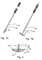
- Figs. 7A and 7B are schematic illustrations of a collapsed and expanded protective device and an attached delivery unit.
- Fig. 8 is a detail of an attachment point of a delivery unit to a protective device 200.
- the attachment point comprises two arms 171, 172.
- This embodiment has improved directional stability facilitating positioning in the aortic arch 100.
- the two arms 171, 172 may also be arranged off-center or asymmetrically.
- the arms may have the function of supporting struts for the selectively permeable unit of the protection device.
- the attachment point of embodiments of the protection device is in some embodiments provided on a surface of the selectively permeable unit 132 devised to be oriented towards the aortic side branch vessels 116, 118, 120 from inside the aortic arch 100 and at a distance from the ostia 116a, 118a, 120a, when the protection unit is positioned in the aortic arch. This is for instance illustrated in Figs. 3 , 4B , 6A .
- a tissue protective unit may be comprised in embodiments of the protection device, such as shown in Fig. 8 .
- the tissue protective unit is provided at the perimeter of the protection device, arranged for apposition to tissue of the aortic arch.
- the tissue protective unit is illustrated as a cuff 210 inflatable via an inflation lumen 211.
- the cuff 210 may also be self-inflatable.
- the cuff 210 may for instance be made of GoreTex® material. When inflated, the cuff 210 provides a protective cushion for particular tissue friendly apposition to the inner aortic arch wall. Even when the cuff 210 is not inflated it provides a certain degree of tissue protection, as it is hollow.
- the tissue protective unit may be a soft and/or elastic material in the form of a coating or surface layer of the perimeter of the protection device.
- the tissue protective unit may be hollow, porous, spongy, and/or resilient.
- the tissue protective unit may be made of a swellable material that swells when in contact with blood.
- swellable materials are for instance swellable polymers, such as disclosed in PCT/EP2007/061116 , which is incorporated by reference in its entirety herein for all purposes.
- the degree of swelling is suitably chosen to provide the protective cushioning effect.
- Such devices, or devices with inflatable cuffs are advantageously delivered in a compact state.
- the protection device is advantageously leak tight, without damaging the aorta wall, during delivery thereof or when in position in the aortic arch 100.
- the selectively permeable unit 132, and thus the protective unit 200 is non-tubular, extending substantially planar in the expanded state.
- the substantially planar shape includes a flat cupped, inverted umbrella, mushroom, or parachute shapes, as shown in the Figures.
- “Flat” in this context means that the thickness of the device 200 is substantially smaller than the longitudinal extension thereof. Moreover, “flat” means such dimensions perpendicular to the longitudinal extension of the protective material, that blood flow through the aortic arch is not hindered by the protective device 200.
- the perimeter of the device 200 is configured for tissue apposition in the aortic arch.
- the shape of the perimeter may be circular, oval, elongate, or even patient-configured adapted to the specific anatomical situation of the patient to be protected by the protective device.
- Patient-configured devices may be based on data derived from image modalities like CT, MR or Ultrasound.
- the device may thus be provided in various longitudinal and transversal extensions, and symmetries.
- the device may be adapted to the shape of the side branch vessel ostia, see e.g. Figs. 4A or 5B .
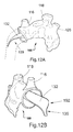
- Wing sections of the protective device may be shaped to extend a certain distance down into the ascendant and/or descendant aorta in order to further improve stability and/or sealing efficiency at the periphery 180 of the protection device 200. Wing sections are e.g. illustrated in Figs. 12A and 12B .
- a plurality of sub-sections of the protection device may be arranged as multi-layers inside each other. In this manner a plurality of peripheral support units and/or sealing units may be provided in series, in order to further improve stability and/or sealing efficiency at the periphery 180 of the protection device 200.
- the selectively permeable unit is non-tubular, extending substantially planar, which peripheral edge is formed by the first support member 133.
- the first side of the device 200 is devised to be oriented towards the aortic side branch vessels from inside the aortic arch when the protection unit is positioned in the aortic arch, in the expanded state.
- the selectively permeable unit 132 is devised to be arranged at a distance from ostia of the aortic side branch vessels of the aortic arch, when the protection unit 200 is positioned in the aortic arch 100, in the expanded state.
- the selectively permeable unit 132 is in some embodiments a rigid, non-elastic material, substantially non-flexible, material, which is non-conformable to ostia of the side branch vessels.
- the support frame of the periphery of the device 200 may provide this rigidity to the device.
- the selectively permeable unit 132 may be stretched by the support frame in the expanded state of the device 200.
- a mechanical protective function of certain tissue or certain organs in the vicinity of the device is provided, when the device is at its position in the body.
- a protection of the aorta side branch vessels' ostia, i.e. the tissue islands of the side branch vessels in the aortic arch is provided.
- the tissue islands are protected from mechanical compression by means of the protection device.
- Mechanical compression may for instance arise from other devices that are manipulated in the aortic arch when the protection device is positioned therein.
- Other devices comprise transvascular medical instruments, such as surgical instruments, guidewires, catheters, balloons, filters, ablation instruments, intracardiac electrodes, etc.
- the protection device lies like a cover or lid (planar or in an inverted flat umbrella /mushroom / parachute shape) over the ostia, at a distance there from, a certain movement towards the ostia due to mechanical pressure from inside the aorta arch is permitted by the protective device.
- the protective device may comprise struts across which the selectively permeable material of the unit 132 is arranged.
- the struts are configured to provide a counter force, such that the selectively permeable unit resiliently returns to an initial position upon a mechanical compression.
- a plurality of struts may be arranged like struts supporting fabric of an umbrella.
- the struts may be of a resilient material.
- the struts may be implemented in from of thicker wires in the braiding.
- the remaining braiding may be made of thinner wires and thus provide the selectively permeability of the selectively permeable unit.
- the struts keep up and support the selectively permeable material of unit 132.
- the struts may be implemented as a plurality of arms 171, 172.
- the struts are provided as a protective framework for the selectively permeable unit of the protection device.
- the selectively permeable unit 132 is a mesh material comprising a mesh of strands.
- the strands may be of a metallic material, such as stainless steel or Nitinol.
- at least some of the strands may be made of a polymeric material, such as a shape memory polymer.
- the mesh of strands forming the protection device may be made of a heat set braiding.
- the expanded configuration of the device is set.
- the collapsed device returns to the heat set shape upon delivery. This may be based on an elastic return or a shape memory effect.
- a manufacturing method that may be modified for protection devices according to the invention is disclosed in WO9742878A1 and WO9912478A1 of AGA Medical Corporation, which are incorporated by reference in their entirety herein for all purposes.
- a fabric of resilient metal fabric material is brought to a desired expanded configuration by a mould in a heat setting process.
- the mould has a shape corresponding to the shape of the protection device in its expanded shape, e.g. the planar shape, or the flat parachute, mushroom, or umbrella shape described herein.
- the metal fabric is formed from a plurality of metal strands and is heat treated within the mold in order to substantially set the desired shape of the device.
- the medical device may include a fastener for attaching to the end of a guide wire or delivery catheter.
- the shape of the medical device may be formed such that the fastener is attached to the metal fabric within a recess formed in the shape of the medical device.
- the device is capable of assuming both an expanded configuration and a collapsed configuration. Once expelled out of a delivery catheter the device returns to its expanded configuration, e.g. in either a planar shape, or a generally flat umbrella-shaped configuration, a generally flat mushroom-shaped configuration, or a generally flat parachute-shaped configuration.
- the protective device may be made of plural layers of fabric, such as disclosed in WO07149107A1 of AGA Medical Corporation, which is incorporated by reference in its entirety herein for all purposes.
- the collapsible medical protection device is shaped from plural layers of a heat-treatable metal fabric. Each of the fabric layers is formed from a plurality of metal strands and the assembly is heat-treated within a mold in order to substantially set a desired shape of the device.
- the strands of the braiding of the protective device is for instance made of NiTinol.
- NiTinol is a superelastic material ensuring that the compressed device reliable returns to its heats set shape when released from the delivery catheter.
- a protective framework may be implemented in from of thicker wires provided within the braiding.
- the protective framework may be implemented in from of a separate layer of a multi-layer braided structure.
- the braiding may has rounded edges at the periphery 180, similar to that shown in Fig. 8 .
- the braided fabric has edges that are provided as tissue protection units, adapted to be appositioned to the aortic wall tissue without damaging the latter.
- the braid may have a support frame, e.g. shown in Figs. 10A or 11 .
- the selectively permeable unit 132 can comprise a hydrophobic material, or comprises a hydrophobic agent, or be made of such a material. This is particularly advantageous to prevent trapping of embolic material in the selectively permeable unit 132.
- the selectively permeable unit 132 may be devised to substantially not trap the embolic material in the selectively permeable unit.
- the selectively permeable unit 132 is devised to releasably trap at least a part of the embolic material 150 from the blood flow in the aortic arch 100.
- the embolic material may e.g. be trapped in pores or a filter structure of the permeable unit 132.
- the selectively permeable unit 132 is devised to be repellant to embolic material.
- embolic material glides of the selectively permeable unit 132 when the protection device 200 is positioned inside the aortic arch.
- a material is e.g. polytetrafluoroethylene PTFE, commercially available as Goretex®.
- the selectively permeable unit 132 comprises a first portion devised to extend in a first direction towards a descending aorta of the aortic arch from the attachment point, and a second portion devised to extend in a second direction, opposite to the first direction, towards the ascending aorta of the aortic arch from the attachment point, when the protection unit is positioned in the aortic arch, in the expanded state.
- the first and second portions may have different longitudinal extensions.
- the selectively permeable unit is arranged to asymmetrically extend from the attachment point in a first direction towards a descending aorta of the aortic arch and in a second direction towards an ascending aorta of the aortic arch, when the protection unit is positioned in the aortic arch, in the expanded state.
- the selectively permeable unit is devised for percutaneous transvascular delivery through one of the aortic side branch vessels to the aortic arch, in a collapsed state.
- the protective device may comprise an additional safety connection in order to prevent loosening of the device into the descending aorta 114.
- the safety connection may comprise a safety wire, thread, tether, string, strand, or similar.
- the safety connection may be attached to the delivery unit or extend all the way through the sheath of the catheter.
- the device has a substantially oval form, approximately 6-10 cm in the longitudinal direction and approximately 3-6 cm in the transversal direction. Wings, or multi-layer structures, as described above, may be provided in addition.
- a mesh size or pore size of a material of the selectively permeable unit 132 may be in the range of 20 ⁇ m to 100 ⁇ m, such as 30-90 ⁇ m or 60-80 ⁇ m. In this manner embolic material is effectively hindered from passing into the side branch vessels, whereas a passage of blood is not substantially hindered. However, as explained above, trapping of embolic particles, i.e. a collection and accumulation thereof, is primarily not provided by the selectively permeable unit 132.
- the selectively material may be manufactured from a flat sheet of material, such as PTFE, which is perforated with holes of suitable diameter to provide the permeability for blood.
- the holes are provided in a sufficient number to not hinder blood flow across the material, while providing the embolic protection.
- Fig. 10A shows permeable material 132 in form of such a flat sheet material.
- a GoreTex® membrane was laser perforated to the desired permeability.
- Fig. 9 is a perspective view of another embodiment having a support member 133 in a generally oval configuration.
- the support member 133 is made of a single wire suitably brought into shape by bending.
- Fig. 9 illustrates the expanded configuration of the protective device.
- Two branches of the wire cross each other at a crossing 196 towards the delivery unit 130.
- the wires are joined at attachment point 131, e.g. by clamping, welding, gluing.
- the delivery device is arranged at an angle with the support member 133 in the longitudinal direction of the device 200.
- This configuration provides for specifically easy introduction into the aortic arch via the left subclavian artery.
- the angled configuration provides for improved leak protection as it is facilitated to provide a force onto the device towards the aortic wall from the delivery unit 130.
- the crossing 196 provides for a certain resiliency or flexibility out of the longitudinal direction of the device.
- Figs. 10A-C are a perspective view, a plan view and a lateral view of another embodiment of the device 200.
- the measurement units in millimeters in Figs. 10B and 10C are solely given as an example and are not to be interpreted as limiting the invention in any way. However, typical dimensions can be seen in the Figs. for a specific embodiment.
- the device illustrated in Figs. 10A-C is also angled (here 106°) and has a crossing 196 of a wire of the support member 133.
- the wire has a first branch 197 and a second branch 198.
- the ovale form has an increasing width towards the distal end of the device. This shape allows for an improved retraction when retracting the device back into the delivery catheter.
- a tongue 199 is arranged at the distal end of the device.
- the tongue 199 is made by suitably bending the wire of the support member 133.
- the tongue has a width B.
- the tongue 199 facilitates introduction of the device into the delivery catheter by bending the two branches 197, 198 towards each other while pushing the distal end into a proximal catheter lumen opening.
- the width B is preferably as large as, or smaller as, the inner diameter of the lumen of the catheter.
- the tongue 199 further is arranged at an angle deviating longitudinally from the protection plane of the permeable unit 132 extending between the expanded lateral branches 197, 198, see Figs. 10A , and 10C .
- This angled arrangement provides for the tongue 199 to be arranged in the aortic arch in smooth apposition to the vessel wall thereof, without damaging the latter.
- such a tongue may be attached to the distal end as a separate element.
- Fig. 11 is a perspective view of another embodiment made of two wires 197, 198.
- the attachment point 131 is integral with the device.
- the two wires are affixed to each other at the proximal portion to constitute the delivery device 130 as a double wire.
- the two wires may be soldered, welded, press-fit, or attached to each other at the proximal portion and the distal portion of the device by other suitable means. Manufacturing of this type of device is particularly advantageous, as it is made time and cost efficiently.
- the distal portion of the device is provided in form of an angled extension or nose 199.
- the selectively permeable unit 132 is arranged substantially planar between the lateral wires 197, 198 extending between the attachment point 131 and the nose 199.
- a typical duration of use of the device is approximately one hour.
- a kit comprises such a collapsible embolic protection device and a transvascular delivery unit adapted for delivery of the collapsible embolic protection device through a side branch vessel of the aortic arch into the aortic arch.
- a particle trap or filter may be arranged proximally on the delivery unit, in combination to the latter.
- a trap or filter may be provided in a separate lumen of the catheter for release in the delivery vessel upstream the ostium of delivery to the aortic arch 100.
- the trap or filter may for instance be a vascular filter for positioning in a lumen of the type as disclosed in WO 2007/035885 , US 2006/0025806 , which are incorporated by reference herein in their entirety for all purposes.
- Suitable commercially available vascular filters, traps or embolic protection devices are e.g. the SpiderFXTM or Fibernet® EP system. Any embolic material that by accident ends up in the delivery vessel is thus securely trapped and removed when withdrawing the combined device 200 and vascular trap.
- the kit may comprise such a vascular particle trap or filter.
- Figs. 12A and 12B are different perspective views of schematic illustrations of a preparation of an aortic arch 100 from animal trials performed to prove the function of the concept of embodiments of the protective device.
- the device comprises a distal wing portion 139 at the distal end 192.
- Five devices were successfully positioned via the subclavian artery 120 in the aortic arch. Passage of embolic material into the carotid arteries was significantly reduced when the protection device was in place.
Priority Applications (1)
| Application Number | Priority Date | Filing Date | Title |
|---|---|---|---|
| EP14183541.3A EP2837360B1 (de) | 2008-09-04 | 2009-09-04 | Temporäre Embolieschutzvorrichtung mit Metallgewebe |
Applications Claiming Priority (3)
| Application Number | Priority Date | Filing Date | Title |
|---|---|---|---|
| US9428308P | 2008-09-04 | 2008-09-04 | |
| SE0801901 | 2008-09-04 | ||
| EP09782655.6A EP2337521B3 (de) | 2008-09-04 | 2009-09-04 | Temporäre embolie-schutzvorrichtung |
Related Parent Applications (3)
| Application Number | Title | Priority Date | Filing Date |
|---|---|---|---|
| EP09782655.6 Division | 2009-09-04 | ||
| EP09782655.6A Division EP2337521B3 (de) | 2008-09-04 | 2009-09-04 | Temporäre embolie-schutzvorrichtung |
| EP09782655.6A Division-Into EP2337521B3 (de) | 2008-09-04 | 2009-09-04 | Temporäre embolie-schutzvorrichtung |
Related Child Applications (2)
| Application Number | Title | Priority Date | Filing Date |
|---|---|---|---|
| EP14183541.3A Division-Into EP2837360B1 (de) | 2008-09-04 | 2009-09-04 | Temporäre Embolieschutzvorrichtung mit Metallgewebe |
| EP14183541.3A Division EP2837360B1 (de) | 2008-09-04 | 2009-09-04 | Temporäre Embolieschutzvorrichtung mit Metallgewebe |
Publications (2)
| Publication Number | Publication Date |
|---|---|
| EP2535018A1 true EP2535018A1 (de) | 2012-12-19 |
| EP2535018B1 EP2535018B1 (de) | 2015-10-21 |
Family
ID=41258202
Family Applications (5)
| Application Number | Title | Priority Date | Filing Date |
|---|---|---|---|
| EP12180197.1A Active EP2537488B1 (de) | 2008-09-04 | 2009-09-04 | Vorrichtung für temporären Embolieschutz |
| EP14183541.3A Active EP2837360B1 (de) | 2008-09-04 | 2009-09-04 | Temporäre Embolieschutzvorrichtung mit Metallgewebe |
| EP12180198.9A Active EP2537489B1 (de) | 2008-09-04 | 2009-09-04 | Vorrichtung für temporären embolieschutz |
| EP09782655.6A Active EP2337521B3 (de) | 2008-09-04 | 2009-09-04 | Temporäre embolie-schutzvorrichtung |
| EP12180196.3A Active EP2535018B1 (de) | 2008-09-04 | 2009-09-04 | Vorrichtung für temporären Embolieschutz |
Family Applications Before (4)
| Application Number | Title | Priority Date | Filing Date |
|---|---|---|---|
| EP12180197.1A Active EP2537488B1 (de) | 2008-09-04 | 2009-09-04 | Vorrichtung für temporären Embolieschutz |
| EP14183541.3A Active EP2837360B1 (de) | 2008-09-04 | 2009-09-04 | Temporäre Embolieschutzvorrichtung mit Metallgewebe |
| EP12180198.9A Active EP2537489B1 (de) | 2008-09-04 | 2009-09-04 | Vorrichtung für temporären embolieschutz |
| EP09782655.6A Active EP2337521B3 (de) | 2008-09-04 | 2009-09-04 | Temporäre embolie-schutzvorrichtung |
Country Status (19)
| Country | Link |
|---|---|
| US (6) | US10610229B2 (de) |
| EP (5) | EP2537488B1 (de) |
| JP (3) | JP5967937B2 (de) |
| KR (2) | KR101720149B1 (de) |
| CN (2) | CN107028678B (de) |
| AU (1) | AU2009289174B2 (de) |
| BR (1) | BRPI0918573A2 (de) |
| CA (2) | CA2976481C (de) |
| CR (1) | CR20110179A (de) |
| DE (7) | DE202009018975U1 (de) |
| DK (2) | DK2537488T3 (de) |
| ES (1) | ES2614186T3 (de) |
| IL (2) | IL211562A (de) |
| MX (1) | MX2011002473A (de) |
| MY (1) | MY178907A (de) |
| RU (1) | RU2518457C2 (de) |
| SG (1) | SG171706A1 (de) |
| WO (1) | WO2010026240A1 (de) |
| ZA (2) | ZA201101990B (de) |
Families Citing this family (65)
| Publication number | Priority date | Publication date | Assignee | Title |
|---|---|---|---|---|
| CA2759746C (en) | 2001-12-05 | 2018-05-22 | Smt Research And Development Ltd. | Endovascular device for entrapment of particulate matter and method for use |
| US9707071B2 (en) | 2004-11-24 | 2017-07-18 | Contego Medical Llc | Percutaneous transluminal angioplasty device with integral embolic filter |
| US20080255603A1 (en) * | 2005-06-10 | 2008-10-16 | Sagax, Inc. | Implant Device Particularly Useful For Implantation In the Intravascular System For Diverting Emboli |
| US20100179647A1 (en) * | 2006-09-11 | 2010-07-15 | Carpenter Judith T | Methods of reducing embolism to cerebral circulation as a consequence of an index cardiac procedure |
| US9339367B2 (en) * | 2006-09-11 | 2016-05-17 | Edwards Lifesciences Ag | Embolic deflection device |
| US20100179583A1 (en) * | 2006-09-11 | 2010-07-15 | Carpenter Judith T | Methods of deploying and retrieving an embolic diversion device |
| US9480548B2 (en) * | 2006-09-11 | 2016-11-01 | Edwards Lifesciences Ag | Embolic protection device and method of use |
| US20100179584A1 (en) * | 2006-09-11 | 2010-07-15 | Carpenter Judith T | Methods of diverting embolic debris away from the cerebral circulation |
| KR101720149B1 (ko) | 2008-09-04 | 2017-03-27 | 앤덜스 존슨 | 일시적인 색전 방지 장치 및 그것의 전달을 위한 의료 방법 |
| WO2010121192A1 (en) * | 2009-04-16 | 2010-10-21 | Cvdevices, Llc | Devices, systems, and methods for the prevention of stroke |
| WO2012085916A2 (en) * | 2010-12-23 | 2012-06-28 | Smt Research And Development Ltd. | Device and method for deflecting emboli in an aorta |
| US8948848B2 (en) | 2011-01-07 | 2015-02-03 | Innovative Cardiovascular Solutions, Llc | Angiography catheter |
| EP2522307B1 (de) | 2011-05-08 | 2020-09-30 | ITSO Medical AB | Vorrichtung zur Lieferung von medizinischen Geräten an eine Herzklappe |
| ITMI20110796A1 (it) * | 2011-05-10 | 2012-11-11 | Fabrizio Farneti | Dispositivo medico impiantabile rimovibile in vasi sanguigni, particolarmente nell'aorta toracica con aneurisma. |
| WO2012160556A1 (en) * | 2011-05-26 | 2012-11-29 | Keystone Heart Ltd. | An embolic filter device and method of use thereof |
| WO2013063124A1 (en) * | 2011-10-25 | 2013-05-02 | Boston Scientific Scimed, Inc. | Embolic debris deflector |
| US8968354B2 (en) | 2011-10-26 | 2015-03-03 | Boston Scientific Scimed, Inc. | Extended protection embolic filter |
| US20130123835A1 (en) * | 2011-11-14 | 2013-05-16 | Boston Scientific Scimed, Inc. | Embolic protection device and method |
| WO2013103979A1 (en) | 2012-01-06 | 2013-07-11 | Emboline, Inc. | Integrated embolic protection devices |
| WO2013126618A1 (en) * | 2012-02-21 | 2013-08-29 | Synecor Llc | Embolic protection system and method for use in an aortic arch |
| US20150039016A1 (en) * | 2012-03-09 | 2015-02-05 | Keystone Heart Ltd. | Device and method for deflecting emboli in an aorta |
| US9888994B2 (en) * | 2012-05-15 | 2018-02-13 | Transverse Medical, Inc. | Catheter-based apparatuses and methods |
| US9707076B2 (en) * | 2012-08-23 | 2017-07-18 | Minimally Invasive Surgical Access Limited | Direct aortic access system for transcatheter aortic valve procedures |
| WO2014032038A1 (en) * | 2012-08-24 | 2014-02-27 | Synecor Llc | System for facilitating transcatheter aortic valve procedures using femoral access |
| US9456834B2 (en) | 2012-10-31 | 2016-10-04 | Covidien Lp | Thrombectomy device with distal protection |
| EP2732794A1 (de) | 2012-11-14 | 2014-05-21 | Contego AB | Verbesserte Embolieschutzvorrichtung und Verfahren |
| US20140257362A1 (en) * | 2013-03-07 | 2014-09-11 | St. Jude Medical, Cardiology Division, Inc. | Filtering and removing particulates from bloodstream |
| CN108852555A (zh) | 2013-03-14 | 2018-11-23 | 瓣膜医学有限公司 | 临时的瓣膜和瓣膜-过滤器 |
| EP2996630B1 (de) | 2013-05-14 | 2022-04-06 | Transverse Medical, Inc. | Katheterbasierte vorrichtungen |
| JP2016527002A (ja) * | 2013-07-17 | 2016-09-08 | レイク リージョン マニュファクチュアリング インコーポレイテッド | 大流量域での塞栓症保護装置 |
| US9402708B2 (en) | 2013-07-25 | 2016-08-02 | Covidien Lp | Vascular devices and methods with distal protection |
| EP2859864A1 (de) * | 2013-10-14 | 2015-04-15 | Protembis GmbH | Medizinische Vorrichtung für Embolieschutz |
| JP6761345B2 (ja) * | 2014-01-10 | 2020-09-23 | キーストーン ハート リミテッド | 生体構造非依存性偏向装置 |
| WO2015177322A1 (en) | 2014-05-21 | 2015-11-26 | Swat Medical Ab | Improved embolic protection device and method |
| EP2987463A1 (de) * | 2014-08-21 | 2016-02-24 | Noureddine Frid | 3D-Filter zur Vorbeugung eines Schlaganfalls |
| KR102452779B1 (ko) * | 2014-09-14 | 2022-10-07 | 엠볼린, 인크. | 색전 보호를 동반하는 도입 시스 |
| WO2016116816A2 (en) * | 2015-01-20 | 2016-07-28 | Keystone Heart Ltd. | Intravascular devices and delivery systems and uses thereof |
| WO2016118958A1 (en) | 2015-01-23 | 2016-07-28 | Contego Medical Llc | Interventional device having an integrated embolic filter and associated methods |
| AU2015411406B2 (en) * | 2015-10-09 | 2019-02-14 | Transverse Medical, Inc. | Catheter-based apparatuses and methods |
| CN105662654A (zh) * | 2016-02-25 | 2016-06-15 | 复旦大学附属中山医院 | 一种冠状动脉保护装置 |
| US11007045B2 (en) | 2016-03-02 | 2021-05-18 | C.R. Bard, Inc. | Embolic protection basket apparatus |
| RU168007U1 (ru) * | 2016-03-09 | 2017-01-16 | Федеральное государственное бюджетное образовательное учреждение высшего образования "Самарский государственный медицинский университет" Министерства здравоохранения Российской Федерации | Устройство для защиты почечных артерий от дистальной эмболии при эндоваскулярных вмешательствах |
| US20190076231A1 (en) | 2016-03-10 | 2019-03-14 | Keystone Heart Ltd. | Intra-Aortic Device |
| ES2941807T3 (es) * | 2016-05-13 | 2023-05-25 | Swiss Vx Venentherapie Und Forschung Gmbh | Dispositivo no implantable para la oclusión temporal de vasos sanguíneos y uso del mismo |
| CN109152908B (zh) | 2016-05-16 | 2021-06-08 | 瓣膜医学有限公司 | 反转的临时瓣膜鞘 |
| DE102016012869A1 (de) * | 2016-10-28 | 2018-05-03 | Protembis Gmbh | Embolieschutzvorrichtung, Verfahren zu deren Faltung und Formvorrichtung |
| US11337790B2 (en) * | 2017-02-22 | 2022-05-24 | Boston Scientific Scimed, Inc. | Systems and methods for protecting the cerebral vasculature |
| EP3585305A1 (de) * | 2017-02-23 | 2020-01-01 | Boston Scientific Scimed, Inc. | Medizinische drainagevorrichtung |
| EP3432825A4 (de) * | 2017-03-27 | 2019-05-22 | Transverse Medical, Inc. | Filtervorrichtungen und -verfahren |
| EP3400901A1 (de) | 2017-05-12 | 2018-11-14 | Keystone Heart Ltd. | Vorrichtung zum filtern von embolischem material in einem gefässsystem |
| EP3476365A1 (de) * | 2017-10-27 | 2019-05-01 | Keystone Heart Ltd. | Kuppelförmige filtervorrichtung und verfahren zur herstellung davon |
| USD908875S1 (en) * | 2017-11-09 | 2021-01-26 | Keystone Heart Ltd. | Medical instrument, instrument and tool for laboratory use |
| KR20200130351A (ko) | 2018-03-07 | 2020-11-18 | 이너베이티브 카디오배스큘러 솔류션스, 엘엘씨 | 색전 보호 디바이스 |
| CN110393605B (zh) * | 2018-04-23 | 2022-11-04 | 黄健兵 | 一种主动脉弓部带分支覆膜支架血管组合装置 |
| CN109009563B (zh) * | 2018-08-27 | 2024-01-23 | 复旦大学附属中山医院 | 一种改进的主动脉弓覆膜支架型血管 |
| CN113677296A (zh) | 2019-02-13 | 2021-11-19 | 艾姆伯莱恩公司 | 具有整合的栓塞防护装置的导管 |
| CN109771090B (zh) * | 2019-03-19 | 2020-09-11 | 武汉唯柯医疗科技有限公司 | 预防脑栓塞的血栓过滤器 |
| US11707351B2 (en) | 2019-08-19 | 2023-07-25 | Encompass Technologies, Inc. | Embolic protection and access system |
| US20220331084A1 (en) | 2019-09-19 | 2022-10-20 | Transverse Medical, Inc. | Filter apparatuses and methods |
| CN114901208A (zh) * | 2019-11-01 | 2022-08-12 | 丝路医疗公司 | 用于经导管的主动脉瓣膜治疗的系统和方法 |
| CN112914789A (zh) * | 2020-11-05 | 2021-06-08 | 上海微创医疗器械(集团)有限公司 | 抗栓塞保护装置及医疗器械 |
| RU205369U1 (ru) * | 2020-12-14 | 2021-07-12 | Федеральное государственное бюджетное учреждение высшего образования "Тамбовский государственный технический университет" (ФГБОУ ВО "ТГТУ") | Устройство интраваскулярного зонда для совместного использования ротационной атерэктомии и оптической когерентной томографии |
| CN113229886B (zh) * | 2021-04-16 | 2022-07-01 | 核工业总医院 | 一种脑保护系统 |
| US20230414337A1 (en) * | 2022-06-22 | 2023-12-28 | Fortuna Clinical, Llc | Embolic Protection Device |
| CN115969572B (zh) * | 2023-03-13 | 2023-06-23 | 乐普(北京)医疗器械股份有限公司 | 一种主动脉弓覆膜支架及其输送系统 |
Citations (11)
| Publication number | Priority date | Publication date | Assignee | Title |
|---|---|---|---|---|
| WO1997042878A1 (en) | 1996-05-14 | 1997-11-20 | Aga Medical Corporation | Percutaneous catheter directed intravascular occlusion devices |
| WO1999012478A1 (en) | 1997-09-08 | 1999-03-18 | Aga Medical Corporation | Percutaneous catheter directed occlusion devices |
| US6258120B1 (en) | 1997-12-23 | 2001-07-10 | Embol-X, Inc. | Implantable cerebral protection device and methods of use |
| US20030171803A1 (en) * | 2001-12-05 | 2003-09-11 | Shimon Dov V. | Endovascular device for entrapment of particulate matter and method for use |
| US20040215167A1 (en) | 2002-08-27 | 2004-10-28 | Amir Belson | Embolic protection device |
| US20060025806A1 (en) | 2001-07-24 | 2006-02-02 | Jeffrey Krolik | Apparatus and methods for aspirating emboli |
| US20060241678A1 (en) * | 2005-01-03 | 2006-10-26 | Eric Johnson | Retrievable endoluminal filter |
| WO2007035885A2 (en) | 2005-09-20 | 2007-03-29 | Emerge Medsystems, Llc | Embolic filter device and related systems and methods |
| WO2007129323A2 (en) * | 2006-05-08 | 2007-11-15 | Sagax, Inc. | Device and method for vascular filter |
| WO2007149107A1 (en) | 2006-06-23 | 2007-12-27 | Aga Medical Corporation | Multi-layer braided structures for occluding vascular defects and for occluding fluid flow through portions of the vasculature of the body |
| US20080065145A1 (en) | 2006-09-11 | 2008-03-13 | Carpenter Judith T | Embolic protection device and method of use |
Family Cites Families (33)
| Publication number | Priority date | Publication date | Assignee | Title |
|---|---|---|---|---|
| SU764684A1 (ru) * | 1978-01-31 | 1980-09-25 | Челябинский государственный медицинский институт | Фильтр-ловушка |
| US6350266B1 (en) * | 1995-02-02 | 2002-02-26 | Scimed Life Systems, Inc. | Hybrid stone retrieval device |
| US5911734A (en) * | 1997-05-08 | 1999-06-15 | Embol-X, Inc. | Percutaneous catheter and guidewire having filter and medical device deployment capabilities |
| US6245088B1 (en) * | 1997-07-07 | 2001-06-12 | Samuel R. Lowery | Retrievable umbrella sieve and method of use |
| US6371935B1 (en) * | 1999-01-22 | 2002-04-16 | Cardeon Corporation | Aortic catheter with flow divider and methods for preventing cerebral embolization |
| US6395014B1 (en) * | 1997-09-26 | 2002-05-28 | John A. Macoviak | Cerebral embolic protection assembly and associated methods |
| US6361545B1 (en) * | 1997-09-26 | 2002-03-26 | Cardeon Corporation | Perfusion filter catheter |
| BR9813935A (pt) * | 1997-11-07 | 2000-09-19 | Salviac Ltd | Dispositivos de filtragem vascular para remoção de material embólico de fluidos corpóreos |
| IL128938A0 (en) * | 1999-03-11 | 2000-02-17 | Mind Guard Ltd | Implantable stroke treating device |
| CA2378715C (en) * | 1999-07-30 | 2011-09-06 | Incept Llc | Vascular device for emboli, thrombus and foreign body removal and methods of use |
| US6235044B1 (en) | 1999-08-04 | 2001-05-22 | Scimed Life Systems, Inc. | Percutaneous catheter and guidewire for filtering during ablation of mycardial or vascular tissue |
| US6689150B1 (en) | 1999-10-27 | 2004-02-10 | Atritech, Inc. | Filter apparatus for ostium of left atrial appendage |
| US6663650B2 (en) * | 2000-06-29 | 2003-12-16 | Concentric Medical, Inc. | Systems, methods and devices for removing obstructions from a blood vessel |
| IL137326A0 (en) * | 2000-07-17 | 2001-07-24 | Mind Guard Ltd | Implantable braided stroke preventing device and method of manufacturing |
| EP1231194B1 (de) | 2001-02-10 | 2003-11-12 | Oxeno Olefinchemie GmbH | Herstellung von 1-Olefinen |
| US7214237B2 (en) * | 2001-03-12 | 2007-05-08 | Don Michael T Anthony | Vascular filter with improved strength and flexibility |
| US6878153B2 (en) * | 2001-07-02 | 2005-04-12 | Rubicon Medical, Inc. | Methods, systems, and devices for providing embolic protection and removing embolic material |
| US6958074B2 (en) * | 2002-01-07 | 2005-10-25 | Cordis Corporation | Releasable and retrievable vascular filter system |
| US7137991B2 (en) * | 2003-02-24 | 2006-11-21 | Scimed Life Systems, Inc. | Multi-wire embolic protection filtering device |
| DE10318639A1 (de) | 2003-04-24 | 2004-11-11 | Robert Bosch Gmbh | Brennstoffeinspritzventil |
| WO2006055052A2 (en) * | 2004-07-19 | 2006-05-26 | Michael Gertner | Methods and devices for chronic embolic protection |
| US20060020285A1 (en) * | 2004-07-22 | 2006-01-26 | Volker Niermann | Method for filtering blood in a vessel with helical elements |
| US20080147111A1 (en) * | 2005-01-03 | 2008-06-19 | Eric Johnson | Endoluminal Filter With Fixation |
| US20060161241A1 (en) | 2005-01-14 | 2006-07-20 | Denise Barbut | Methods and devices for treating aortic atheroma |
| US20060253148A1 (en) * | 2005-05-04 | 2006-11-09 | Leone James E | Apparatus and method of using an occluder for embolic protection |
| RU2294717C2 (ru) * | 2005-09-29 | 2007-03-10 | Александр Наумович Балан | Устройство для защиты сосудов большого диаметра при осуществлении манипуляций |
| US8632562B2 (en) * | 2005-10-03 | 2014-01-21 | Cook Medical Technologies Llc | Embolic protection device |
| WO2007049677A1 (ja) | 2005-10-27 | 2007-05-03 | Kao Corporation | 脱酸素剤、脱酸素剤中間体、脱酸素剤複合体及びその製造方法 |
| JP4925650B2 (ja) | 2005-11-28 | 2012-05-09 | 東京エレクトロン株式会社 | 基板処理装置 |
| EP2217152A1 (de) | 2007-10-17 | 2010-08-18 | Syntach AG | Die form verändernde medizinische vorrichtung, kit, herstellungsverfahren und anwendungsverfahren |
| AU2009232400B2 (en) * | 2008-04-03 | 2013-09-12 | Cook Medical Technologies Llc | Self cleaning devices, systems and methods of use |
| JP5762955B2 (ja) * | 2008-06-23 | 2015-08-12 | ルーメン・バイオメディカル・インコーポレイテッドLumen Biomedical, Inc. | 経皮的心臓弁置換および類似処置時の塞栓予防 |
| KR101720149B1 (ko) | 2008-09-04 | 2017-03-27 | 앤덜스 존슨 | 일시적인 색전 방지 장치 및 그것의 전달을 위한 의료 방법 |
-
2009
- 2009-09-04 KR KR1020117007742A patent/KR101720149B1/ko active IP Right Grant
- 2009-09-04 DE DE202009018975.9U patent/DE202009018975U1/de not_active Expired - Lifetime
- 2009-09-04 CA CA2976481A patent/CA2976481C/en active Active
- 2009-09-04 EP EP12180197.1A patent/EP2537488B1/de active Active
- 2009-09-04 DK DK12180197.1T patent/DK2537488T3/en active
- 2009-09-04 MX MX2011002473A patent/MX2011002473A/es active IP Right Grant
- 2009-09-04 US US13/062,499 patent/US10610229B2/en active Active
- 2009-09-04 CN CN201610834884.XA patent/CN107028678B/zh active Active
- 2009-09-04 WO PCT/EP2009/061509 patent/WO2010026240A1/en active Application Filing
- 2009-09-04 SG SG2011016367A patent/SG171706A1/en unknown
- 2009-09-04 DK DK09782655.6T patent/DK2337521T6/en active
- 2009-09-04 DE DE202009018998.8U patent/DE202009018998U1/de not_active Expired - Lifetime
- 2009-09-04 EP EP14183541.3A patent/EP2837360B1/de active Active
- 2009-09-04 DE DE202009019000.5U patent/DE202009019000U1/de not_active Expired - Lifetime
- 2009-09-04 DE DE202009018977.5U patent/DE202009018977U1/de not_active Expired - Lifetime
- 2009-09-04 AU AU2009289174A patent/AU2009289174B2/en active Active
- 2009-09-04 EP EP12180198.9A patent/EP2537489B1/de active Active
- 2009-09-04 DE DE202009019019.6U patent/DE202009019019U1/de not_active Expired - Lifetime
- 2009-09-04 DE DE202009018976.7U patent/DE202009018976U1/de not_active Expired - Lifetime
- 2009-09-04 MY MYPI2011000995A patent/MY178907A/en unknown
- 2009-09-04 CA CA2824897A patent/CA2824897C/en active Active
- 2009-09-04 CN CN200980143474.9A patent/CN102256566B/zh active Active
- 2009-09-04 BR BRPI0918573A patent/BRPI0918573A2/pt not_active Application Discontinuation
- 2009-09-04 KR KR1020177007726A patent/KR101772089B1/ko active IP Right Grant
- 2009-09-04 ES ES12180198.9T patent/ES2614186T3/es active Active
- 2009-09-04 EP EP09782655.6A patent/EP2337521B3/de active Active
- 2009-09-04 JP JP2011525568A patent/JP5967937B2/ja active Active
- 2009-09-04 EP EP12180196.3A patent/EP2535018B1/de active Active
- 2009-09-04 DE DE202009018999.6U patent/DE202009018999U1/de not_active Expired - Lifetime
- 2009-09-04 RU RU2011112428/14A patent/RU2518457C2/ru active
-
2011
- 2011-03-03 IL IL211562A patent/IL211562A/en active IP Right Grant
- 2011-04-01 ZA ZA2011/01990A patent/ZA201101990B/en unknown
- 2011-04-01 CR CR20110179A patent/CR20110179A/es not_active Application Discontinuation
-
2012
- 2012-08-02 ZA ZA2012/05823A patent/ZA201205823B/en unknown
-
2013
- 2013-03-21 US US13/848,673 patent/US8974490B2/en active Active
- 2013-12-11 IL IL229923A patent/IL229923A/en active IP Right Grant
-
2014
- 2014-05-19 US US14/281,720 patent/US10512468B2/en active Active
- 2014-05-19 US US14/281,734 patent/US9968359B2/en active Active
- 2014-05-19 US US14/281,708 patent/US10575852B2/en active Active
- 2014-09-17 JP JP2014189360A patent/JP6124084B2/ja active Active
-
2017
- 2017-03-21 JP JP2017055130A patent/JP6315359B2/ja active Active
-
2020
- 2020-02-27 US US16/803,901 patent/US20200197016A1/en active Pending
Patent Citations (11)
| Publication number | Priority date | Publication date | Assignee | Title |
|---|---|---|---|---|
| WO1997042878A1 (en) | 1996-05-14 | 1997-11-20 | Aga Medical Corporation | Percutaneous catheter directed intravascular occlusion devices |
| WO1999012478A1 (en) | 1997-09-08 | 1999-03-18 | Aga Medical Corporation | Percutaneous catheter directed occlusion devices |
| US6258120B1 (en) | 1997-12-23 | 2001-07-10 | Embol-X, Inc. | Implantable cerebral protection device and methods of use |
| US20060025806A1 (en) | 2001-07-24 | 2006-02-02 | Jeffrey Krolik | Apparatus and methods for aspirating emboli |
| US20030171803A1 (en) * | 2001-12-05 | 2003-09-11 | Shimon Dov V. | Endovascular device for entrapment of particulate matter and method for use |
| US20040215167A1 (en) | 2002-08-27 | 2004-10-28 | Amir Belson | Embolic protection device |
| US20060241678A1 (en) * | 2005-01-03 | 2006-10-26 | Eric Johnson | Retrievable endoluminal filter |
| WO2007035885A2 (en) | 2005-09-20 | 2007-03-29 | Emerge Medsystems, Llc | Embolic filter device and related systems and methods |
| WO2007129323A2 (en) * | 2006-05-08 | 2007-11-15 | Sagax, Inc. | Device and method for vascular filter |
| WO2007149107A1 (en) | 2006-06-23 | 2007-12-27 | Aga Medical Corporation | Multi-layer braided structures for occluding vascular defects and for occluding fluid flow through portions of the vasculature of the body |
| US20080065145A1 (en) | 2006-09-11 | 2008-03-13 | Carpenter Judith T | Embolic protection device and method of use |
Also Published As
Similar Documents
| Publication | Publication Date | Title |
|---|---|---|
| US20200197016A1 (en) | Temporary Embolic Protection Device And Medical Procedure For Delivery Thereof | |
| EP3586793B1 (de) | Emboliedeflektionsvorrichtung |
Legal Events
| Date | Code | Title | Description |
|---|---|---|---|
| PUAI | Public reference made under article 153(3) epc to a published international application that has entered the european phase |
Free format text: ORIGINAL CODE: 0009012 |
|
| AC | Divisional application: reference to earlier application |
Ref document number: 2337521 Country of ref document: EP Kind code of ref document: P |
|
| AK | Designated contracting states |
Kind code of ref document: A1 Designated state(s): AT BE BG CH CY CZ DE DK EE ES FI FR GB GR HR HU IE IS IT LI LT LU LV MC MK MT NL NO PL PT RO SE SI SK SM TR |
|
| 17P | Request for examination filed |
Effective date: 20130619 |
|
| RBV | Designated contracting states (corrected) |
Designated state(s): AT BE BG CH CY CZ DE DK EE ES FI FR GB GR HR HU IE IS IT LI LT LU LV MC MK MT NL NO PL PT RO SE SI SK SM TR |
|
| RAP1 | Party data changed (applicant data changed or rights of an application transferred) |
Owner name: SWAT MEDICAL AB |
|
| GRAP | Despatch of communication of intention to grant a patent |
Free format text: ORIGINAL CODE: EPIDOSNIGR1 |
|
| INTG | Intention to grant announced |
Effective date: 20150623 |
|
| GRAS | Grant fee paid |
Free format text: ORIGINAL CODE: EPIDOSNIGR3 |
|
| GRAA | (expected) grant |
Free format text: ORIGINAL CODE: 0009210 |
|
| AC | Divisional application: reference to earlier application |
Ref document number: 2337521 Country of ref document: EP Kind code of ref document: P |
|
| AK | Designated contracting states |
Kind code of ref document: B1 Designated state(s): AT BE BG CH CY CZ DE DK EE ES FI FR GB GR HR HU IE IS IT LI LT LU LV MC MK MT NL NO PL PT RO SE SI SK SM TR |
|
| REG | Reference to a national code |
Ref country code: GB Ref legal event code: FG4D |
|
| REG | Reference to a national code |
Ref country code: CH Ref legal event code: EP |
|
| REG | Reference to a national code |
Ref country code: AT Ref legal event code: REF Ref document number: 756076 Country of ref document: AT Kind code of ref document: T Effective date: 20151115 |
|
| REG | Reference to a national code |
Ref country code: IE Ref legal event code: FG4D |
|
| REG | Reference to a national code |
Ref country code: DE Ref legal event code: R096 Ref document number: 602009034431 Country of ref document: DE |
|
| REG | Reference to a national code |
Ref country code: LT Ref legal event code: MG4D |
|
| REG | Reference to a national code |
Ref country code: NL Ref legal event code: FP |
|
| REG | Reference to a national code |
Ref country code: AT Ref legal event code: MK05 Ref document number: 756076 Country of ref document: AT Kind code of ref document: T Effective date: 20151021 |
|
| PG25 | Lapsed in a contracting state [announced via postgrant information from national office to epo] |
Ref country code: ES Free format text: LAPSE BECAUSE OF FAILURE TO SUBMIT A TRANSLATION OF THE DESCRIPTION OR TO PAY THE FEE WITHIN THE PRESCRIBED TIME-LIMIT Effective date: 20151021 Ref country code: NO Free format text: LAPSE BECAUSE OF FAILURE TO SUBMIT A TRANSLATION OF THE DESCRIPTION OR TO PAY THE FEE WITHIN THE PRESCRIBED TIME-LIMIT Effective date: 20160121 Ref country code: HR Free format text: LAPSE BECAUSE OF FAILURE TO SUBMIT A TRANSLATION OF THE DESCRIPTION OR TO PAY THE FEE WITHIN THE PRESCRIBED TIME-LIMIT Effective date: 20151021 Ref country code: IT Free format text: LAPSE BECAUSE OF FAILURE TO SUBMIT A TRANSLATION OF THE DESCRIPTION OR TO PAY THE FEE WITHIN THE PRESCRIBED TIME-LIMIT Effective date: 20151021 Ref country code: IS Free format text: LAPSE BECAUSE OF FAILURE TO SUBMIT A TRANSLATION OF THE DESCRIPTION OR TO PAY THE FEE WITHIN THE PRESCRIBED TIME-LIMIT Effective date: 20160221 Ref country code: LT Free format text: LAPSE BECAUSE OF FAILURE TO SUBMIT A TRANSLATION OF THE DESCRIPTION OR TO PAY THE FEE WITHIN THE PRESCRIBED TIME-LIMIT Effective date: 20151021 |
|
| PG25 | Lapsed in a contracting state [announced via postgrant information from national office to epo] |
Ref country code: AT Free format text: LAPSE BECAUSE OF FAILURE TO SUBMIT A TRANSLATION OF THE DESCRIPTION OR TO PAY THE FEE WITHIN THE PRESCRIBED TIME-LIMIT Effective date: 20151021 Ref country code: GR Free format text: LAPSE BECAUSE OF FAILURE TO SUBMIT A TRANSLATION OF THE DESCRIPTION OR TO PAY THE FEE WITHIN THE PRESCRIBED TIME-LIMIT Effective date: 20160122 Ref country code: PT Free format text: LAPSE BECAUSE OF FAILURE TO SUBMIT A TRANSLATION OF THE DESCRIPTION OR TO PAY THE FEE WITHIN THE PRESCRIBED TIME-LIMIT Effective date: 20160222 Ref country code: PL Free format text: LAPSE BECAUSE OF FAILURE TO SUBMIT A TRANSLATION OF THE DESCRIPTION OR TO PAY THE FEE WITHIN THE PRESCRIBED TIME-LIMIT Effective date: 20151021 Ref country code: LV Free format text: LAPSE BECAUSE OF FAILURE TO SUBMIT A TRANSLATION OF THE DESCRIPTION OR TO PAY THE FEE WITHIN THE PRESCRIBED TIME-LIMIT Effective date: 20151021 Ref country code: SE Free format text: LAPSE BECAUSE OF FAILURE TO SUBMIT A TRANSLATION OF THE DESCRIPTION OR TO PAY THE FEE WITHIN THE PRESCRIBED TIME-LIMIT Effective date: 20151021 Ref country code: FI Free format text: LAPSE BECAUSE OF FAILURE TO SUBMIT A TRANSLATION OF THE DESCRIPTION OR TO PAY THE FEE WITHIN THE PRESCRIBED TIME-LIMIT Effective date: 20151021 |
|
| REG | Reference to a national code |
Ref country code: DE Ref legal event code: R026 Ref document number: 602009034431 Country of ref document: DE |
|
| PG25 | Lapsed in a contracting state [announced via postgrant information from national office to epo] |
Ref country code: CZ Free format text: LAPSE BECAUSE OF FAILURE TO SUBMIT A TRANSLATION OF THE DESCRIPTION OR TO PAY THE FEE WITHIN THE PRESCRIBED TIME-LIMIT Effective date: 20151021 |
|
| PLBI | Opposition filed |
Free format text: ORIGINAL CODE: 0009260 |
|
| 26 | Opposition filed |
Opponent name: KEYSTONE HEART LTD. Effective date: 20160721 |
|
| PG25 | Lapsed in a contracting state [announced via postgrant information from national office to epo] |
Ref country code: SM Free format text: LAPSE BECAUSE OF FAILURE TO SUBMIT A TRANSLATION OF THE DESCRIPTION OR TO PAY THE FEE WITHIN THE PRESCRIBED TIME-LIMIT Effective date: 20151021 Ref country code: RO Free format text: LAPSE BECAUSE OF FAILURE TO SUBMIT A TRANSLATION OF THE DESCRIPTION OR TO PAY THE FEE WITHIN THE PRESCRIBED TIME-LIMIT Effective date: 20151021 Ref country code: SK Free format text: LAPSE BECAUSE OF FAILURE TO SUBMIT A TRANSLATION OF THE DESCRIPTION OR TO PAY THE FEE WITHIN THE PRESCRIBED TIME-LIMIT Effective date: 20151021 Ref country code: EE Free format text: LAPSE BECAUSE OF FAILURE TO SUBMIT A TRANSLATION OF THE DESCRIPTION OR TO PAY THE FEE WITHIN THE PRESCRIBED TIME-LIMIT Effective date: 20151021 Ref country code: DK Free format text: LAPSE BECAUSE OF FAILURE TO SUBMIT A TRANSLATION OF THE DESCRIPTION OR TO PAY THE FEE WITHIN THE PRESCRIBED TIME-LIMIT Effective date: 20151021 |
|
| PLAX | Notice of opposition and request to file observation + time limit sent |
Free format text: ORIGINAL CODE: EPIDOSNOBS2 |
|
| REG | Reference to a national code |
Ref country code: FR Ref legal event code: PLFP Year of fee payment: 8 |
|
| PG25 | Lapsed in a contracting state [announced via postgrant information from national office to epo] |
Ref country code: SI Free format text: LAPSE BECAUSE OF FAILURE TO SUBMIT A TRANSLATION OF THE DESCRIPTION OR TO PAY THE FEE WITHIN THE PRESCRIBED TIME-LIMIT Effective date: 20151021 |
|
| PLBP | Opposition withdrawn |
Free format text: ORIGINAL CODE: 0009264 |
|
| PG25 | Lapsed in a contracting state [announced via postgrant information from national office to epo] |
Ref country code: BE Free format text: LAPSE BECAUSE OF FAILURE TO SUBMIT A TRANSLATION OF THE DESCRIPTION OR TO PAY THE FEE WITHIN THE PRESCRIBED TIME-LIMIT Effective date: 20151021 |
|
| PLBB | Reply of patent proprietor to notice(s) of opposition received |
Free format text: ORIGINAL CODE: EPIDOSNOBS3 |
|
| PLBD | Termination of opposition procedure: decision despatched |
Free format text: ORIGINAL CODE: EPIDOSNOPC1 |
|
| REG | Reference to a national code |
Ref country code: DE Ref legal event code: R100 Ref document number: 602009034431 Country of ref document: DE |
|
| PG25 | Lapsed in a contracting state [announced via postgrant information from national office to epo] |
Ref country code: MC Free format text: LAPSE BECAUSE OF FAILURE TO SUBMIT A TRANSLATION OF THE DESCRIPTION OR TO PAY THE FEE WITHIN THE PRESCRIBED TIME-LIMIT Effective date: 20151021 |
|
| REG | Reference to a national code |
Ref country code: CH Ref legal event code: PL |
|
| REG | Reference to a national code |
Ref country code: IE Ref legal event code: MM4A |
|
| PLBM | Termination of opposition procedure: date of legal effect published |
Free format text: ORIGINAL CODE: 0009276 |
|
| STAA | Information on the status of an ep patent application or granted ep patent |
Free format text: STATUS: OPPOSITION PROCEDURE CLOSED |
|
| PG25 | Lapsed in a contracting state [announced via postgrant information from national office to epo] |
Ref country code: LI Free format text: LAPSE BECAUSE OF NON-PAYMENT OF DUE FEES Effective date: 20160930 Ref country code: IE Free format text: LAPSE BECAUSE OF NON-PAYMENT OF DUE FEES Effective date: 20160904 Ref country code: CH Free format text: LAPSE BECAUSE OF NON-PAYMENT OF DUE FEES Effective date: 20160930 |
|
| 27C | Opposition proceedings terminated |
Effective date: 20170402 |
|
| PG25 | Lapsed in a contracting state [announced via postgrant information from national office to epo] |
Ref country code: LU Free format text: LAPSE BECAUSE OF NON-PAYMENT OF DUE FEES Effective date: 20160904 |
|
| REG | Reference to a national code |
Ref country code: FR Ref legal event code: PLFP Year of fee payment: 9 |
|
| PG25 | Lapsed in a contracting state [announced via postgrant information from national office to epo] |
Ref country code: CY Free format text: LAPSE BECAUSE OF FAILURE TO SUBMIT A TRANSLATION OF THE DESCRIPTION OR TO PAY THE FEE WITHIN THE PRESCRIBED TIME-LIMIT Effective date: 20151021 Ref country code: HU Free format text: LAPSE BECAUSE OF FAILURE TO SUBMIT A TRANSLATION OF THE DESCRIPTION OR TO PAY THE FEE WITHIN THE PRESCRIBED TIME-LIMIT; INVALID AB INITIO Effective date: 20090904 |
|
| PG25 | Lapsed in a contracting state [announced via postgrant information from national office to epo] |
Ref country code: MK Free format text: LAPSE BECAUSE OF FAILURE TO SUBMIT A TRANSLATION OF THE DESCRIPTION OR TO PAY THE FEE WITHIN THE PRESCRIBED TIME-LIMIT Effective date: 20151021 Ref country code: TR Free format text: LAPSE BECAUSE OF FAILURE TO SUBMIT A TRANSLATION OF THE DESCRIPTION OR TO PAY THE FEE WITHIN THE PRESCRIBED TIME-LIMIT Effective date: 20151021 Ref country code: MT Free format text: LAPSE BECAUSE OF NON-PAYMENT OF DUE FEES Effective date: 20160930 |
|
| REG | Reference to a national code |
Ref country code: FR Ref legal event code: PLFP Year of fee payment: 10 |
|
| PG25 | Lapsed in a contracting state [announced via postgrant information from national office to epo] |
Ref country code: BG Free format text: LAPSE BECAUSE OF FAILURE TO SUBMIT A TRANSLATION OF THE DESCRIPTION OR TO PAY THE FEE WITHIN THE PRESCRIBED TIME-LIMIT Effective date: 20151021 |
|
| P01 | Opt-out of the competence of the unified patent court (upc) registered |
Effective date: 20230529 |
|
| PGFP | Annual fee paid to national office [announced via postgrant information from national office to epo] |
Ref country code: NL Payment date: 20230927 Year of fee payment: 15 Ref country code: GB Payment date: 20230904 Year of fee payment: 15 |
|
| PGFP | Annual fee paid to national office [announced via postgrant information from national office to epo] |
Ref country code: FR Payment date: 20230904 Year of fee payment: 15 Ref country code: DE Payment date: 20230927 Year of fee payment: 15 |