EP2532049B1 - Gefaltete zweipolige planarantenne - Google Patents
Gefaltete zweipolige planarantenne Download PDFInfo
- Publication number
- EP2532049B1 EP2532049B1 EP11708903.7A EP11708903A EP2532049B1 EP 2532049 B1 EP2532049 B1 EP 2532049B1 EP 11708903 A EP11708903 A EP 11708903A EP 2532049 B1 EP2532049 B1 EP 2532049B1
- Authority
- EP
- European Patent Office
- Prior art keywords
- antenna
- radiating plate
- plane
- wing
- distance
- Prior art date
- Legal status (The legal status is an assumption and is not a legal conclusion. Google has not performed a legal analysis and makes no representation as to the accuracy of the status listed.)
- Not-in-force
Links
Images

Classifications
-
- H—ELECTRICITY
- H01—ELECTRIC ELEMENTS
- H01Q—ANTENNAS, i.e. RADIO AERIALS
- H01Q9/00—Electrically-short antennas having dimensions not more than twice the operating wavelength and consisting of conductive active radiating elements
- H01Q9/04—Resonant antennas
- H01Q9/16—Resonant antennas with feed intermediate between the extremities of the antenna, e.g. centre-fed dipole
- H01Q9/28—Conical, cylindrical, cage, strip, gauze, or like elements having an extended radiating surface; Elements comprising two conical surfaces having collinear axes and adjacent apices and fed by two-conductor transmission lines
- H01Q9/285—Planar dipole
-
- H—ELECTRICITY
- H01—ELECTRIC ELEMENTS
- H01Q—ANTENNAS, i.e. RADIO AERIALS
- H01Q19/00—Combinations of primary active antenna elements and units with secondary devices, e.g. with quasi-optical devices, for giving the antenna a desired directional characteristic
- H01Q19/28—Combinations of primary active antenna elements and units with secondary devices, e.g. with quasi-optical devices, for giving the antenna a desired directional characteristic using a secondary device in the form of two or more substantially straight conductive elements
- H01Q19/30—Combinations of primary active antenna elements and units with secondary devices, e.g. with quasi-optical devices, for giving the antenna a desired directional characteristic using a secondary device in the form of two or more substantially straight conductive elements the primary active element being centre-fed and substantially straight, e.g. Yagi antenna
-
- H—ELECTRICITY
- H01—ELECTRIC ELEMENTS
- H01Q—ANTENNAS, i.e. RADIO AERIALS
- H01Q9/00—Electrically-short antennas having dimensions not more than twice the operating wavelength and consisting of conductive active radiating elements
- H01Q9/04—Resonant antennas
- H01Q9/16—Resonant antennas with feed intermediate between the extremities of the antenna, e.g. centre-fed dipole
- H01Q9/26—Resonant antennas with feed intermediate between the extremities of the antenna, e.g. centre-fed dipole with folded element or elements, the folded parts being spaced apart a small fraction of operating wavelength
Definitions
- the present invention generally relates to antennas adapted to transmit and receive UHF signals of the TNT (Digital Terrestrial Television) or analog type, in a frequency band more particularly between 471 and 783 MHz.
- TNT Digital Terrestrial Television
- the rake antennas comprise a plurality of rods mounted on a support arm, including a rear rod called reflector, an intermediate rod said radiating and a front rod called director. These different rods are tuned according to the wavelengths of the signals to be received.
- the radiating rod constitutes the active element of this antenna, since it transmits the UHF signals to the television set via a coaxial cable. It forms a loop around the support arm, with two strands respectively connected to the inner and outer electrical conductors of the coaxial cable. This radiating stem is commonly called a paper clip.
- FR 2 841 688 a plane antenna comprising a rectangular radiating plate open by two parallel main slots connected to one another by a slot of small width. Thanks to these slots, this antenna has a broad frequency band for transmitting and receiving signals. This antenna is in particular adapted to receive all the frequencies of UHF signals TNT type.
- the main disadvantage of this antenna is that the slots, which are cut into the radiating plate at a distance from its peripheral edge and which are sized to match the frequencies of the UHF type signals TNT, require the use of a large radiating plate, to the detriment of the size of the antenna.
- Document is also known WO2005 / 041355 an antenna of the "folded doublet" type, which comprises, on the one hand, a flat plate in which are formed three T-shaped slots which delimit two wings, and, on the other hand, a cable of which a conductor is connected to the one of these two wings and another driver is connected to the other of these two wings.
- the connection of the electrical conductors is here carried out on tabs which extend in extension of the wings.
- the present invention proposes an antenna having dimensions reduced by approximately 40% compared to the antenna disclosed in the document.
- FR 2 841 688 for a substantially identical gain over the entire frequency band of UHF signals TNT type, and which has an optimum impedance.
- the radiating plate forms a doublet folded in the manner of a staple, the two ends of which delimit the third slot. Thanks to this folded staple form, the radiating plate of the antenna has a small footprint. It is further adapted to radiate over a sufficiently wide frequency band to capture all the UHF signals of the TNT type.
- the connection of the electrical conduction element to the wings finally allows the antenna to be perfectly tuned impedance, so that it has a significant gain for capturing signals of reduced power.
- the plane antenna 1 is designed to pick up UHF signals. It is also designed to have a significant gain, so as to capture low power signals.
- This flat antenna 1 is thus particularly adapted to the reception of digital terrestrial television (DTT) type digital radio signals whose power is often inferior to that of the radio analogue signals.
- DTT digital terrestrial television
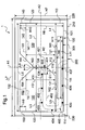
- This flat antenna 1 is directive. It is therefore designed to be placed in an optimal position of receiving signals, facing the main direction of propagation of the signals. In this position, the height and the width of the plane antenna are respectively defined as the two vertical and horizontal dimensions of this plane antenna 1, which are perpendicular to said main direction of propagation of the signals.
- This plane antenna 1 comprises two essential elements, namely a radiating plate 100 and an electric cable 400 connected to this radiating plate 100.
- the radiating plate 100 constitutes the active element of this plane antenna 1, since it transmits the signals to the television set via the electric cable 400.
- the radiating plate 100 is substantially rectangular and flat. It is cut so as to delimit three slots 161, 162, 163 in T, of which only one of the slots 163 opens on the rectangular peripheral edge 101 of this radiating plate 100.
- the two slots 161, 162 which form the base of the T then define, with the lower side of the peripheral edge 101 of the radiating plate 100, a so-called support portion 110.
- the third slot 163 which forms the foot of the T defines, in turn, with the upper side of the peripheral edge 101 of the radiating plate 100 and with the two slots 161, 162, two wings 120, 130.
- the electrical conductors 401, 402 of the electrical cable 400 are respectively connected to these two wings 120, 130.
- this plane antenna 1 also comprises, on either side of the radiating plate 100, a reflector 200 and a director 300. These two elements 200, 300 are tuned in frequency with the radiating plate 100 to allow performance optimization of the radiant plate 100.
- planar antenna 1 is devoid of one and / or the other of these two elements 200, 300, in which case it would however have reduced performance.
- the radiating plate 100 forms a folded and flat doublet, which can be likened to the trombone rod of a rakes antenna.
- This radiating plate 100 here has a vertical axis of symmetry A1.
- the radiating plate 100 has a reduced footprint of the order of 40% compared to a standard flat antenna, and therefore a lower wind resistance.
- the total width L6 of the radiating plate 100 is chosen as a function of the low frequency of the plane antenna 1.
- the radiating plate 100 has a total width L6 equal, within 20%, to 200 millimeters.
- the total height H6 of the radiating plate 100 is in turn chosen according to the high frequency of the plane antenna 1. It is not chosen to be higher, so as not to reduce the gain of the antenna plane 1.
- the radiating plate 100 has a total height H6 equal, within 20%, to 100 millimeters.
- the thickness of the radiating plate 100 is here particularly small, of the order of 0.3 millimeters, so as to reduce the cost of the raw materials necessary for the manufacture of the plane antenna 1.
- the support portion 110 of the radiating plate 100 has an elongate rectangle shape along the width of the antenna. It therefore has a lower edge 111 and an upper edge 112 parallel to each other, and two end edges 113, 114 also parallel to each other.
- Each wing 120, 130 has a rectangular flat plate shape elongated along the width of the antenna, and has a horizontal axis of symmetry A2.
- Each wing 120, 130 therefore has a lower edge 121, 131 and an upper edge 122, 132 parallel to each other, and an outer edge 123, 133 and a free end edge 124, 134 also parallel to each other.
- the free end edges 124, 134 of the two wings are rotated towards each other to define between them the third slot 163.
- Each wing 120, 130 has a height H2, H3 at least twice the height H8 of the support portion 110.
- the two corners of the free end edge 124, 134 of each wing 120, 130 are here and so preferential bevelled at 45 degrees.
- the third slot 163 has a desired length, tuned to the frequency band of TNT type digital radio signals.
- Each wing 120, 130 here has a height H2, H3 equal to 70 millimeters, to 20%.
- the wings 120, 130 also have widths L2, L3 such that the third slot 163 located between their free end edges 124, 134 has a reduced width L8, less than 5 millimeters. Due to this small width, the third slot 163 allows the plane antenna 1 to radiate over the entire frequency band of TNT type digital radio signals.
- Each wing 120, 130 here has a width L2, L3 equal to 98 millimeters, to 20%.
- the wings 120, 130 and the support portion 110 extend edge to edge.
- the lower edge 121, 131 of each wing 120, 130 is attached to the upper edge 112 of the support portion 110 for only a portion of its length.
- the lower edge 121, 131 of each wing 120, 130 is for the remainder remote from the upper edge 112 of the support portion 110 to delimit the first or second slot 161, 162.
- the first and second slots 161, 162 extend in length from the third slot 163 towards the outer edges 123, 133 of the wings 120, 130, to a distance L4, L5 of these edges between 5 and 65 millimeters, and preferably equal to 50 millimeters, to 20%.
- the first and second slots 162, 163 thus have reduced lengths, in favor of the gain of the plane antenna 1.
- each wing 120, 130 is extended on its upper edge 122, 132 by a flap 140, 150 which widens the width of the frequency band at which the plane antenna 1 radiates.
- Each shutter 140, 150 here has a trapezoidal shape, with a lower edge 141, 151 which is attached to the upper edge 122, 132 of the corresponding wing 120, 130, an outer edge 143, 153 which extends the outer edge 123, 133 of the wing 120 130, corresponding, and an inner edge 144, 154 which extends the bevel of the free end edge 124, 134 of the wing 120, 130 corresponding.
- Each shutter 140, 150 here has a height H9, H10 of between 5 and 20 millimeters.
- the radiating plate 100 comes here from forming by cutting a metal strip.
- the material of this metal is chosen to be not only very conductive but also inexpensive.
- the radiating plate 100 is made of a single piece of copper. It could alternatively be cut from a different material, such as for example aluminum or brass.
- the antenna could provide to manufacture the antenna from an integrated circuit comprising a rigid substrate covered on one side by a metal sheet forming said radiating plate.
- This antenna would be less easily recyclable than the antenna described above.
- the electrical cable 400 is designed for transmitting to the demodulator of the television set the signals collected by the radiating plate 100.
- This electrical cable 400 is preferably a coaxial cable comprising a central core 401 surrounded by an insulating dielectric material 403, itself surrounded by a braided conductive sheath, called the shield 402, covered with an insulating envelope (not shown).
- This coaxial cable 400 here has a standard impedance of 75 Ohm, optimized for the transmission of video signals. It is also chosen to present reduced losses.
- the central core 401 of the coaxial cable 400 is connected to the free end edge 124 of the flange 120, while the shield 402 is connected at a distance from the free end edge 134 of the flange 130 so as not to be in direct electrical contact with this free end edge.
- the end of the shield 402 is for this purpose cut away from the end of the central core 401, so that only the insulating dielectric material 403 comes into contact with the free end edge 134 of the flange 130.
- This asymmetry of connection of the coaxial cable 400 on the two wings 120, 130 optimizes the impedance matching of the plane antenna 1, so that it best captures the TNT type digital radio signals.
- the shielding 402 is more precisely here connected to a distance D1 from the free end edge 134 of the wing 130 which is between one fifth and one half of the width L3 of this wing 130.
- the central core 401 is connected to the free end edge 124 of the wing 120 by a single weld point.
- the shield 402 is connected to the flange 130 by four separate welding points 431 - 434 distributed at regular intervals along the cable. It is also connected to the support part 110 by three other soldering points 435 - 437.
- This plurality of soldering points located at a distance from the free end edge 134 of the wing 130, makes it possible to reduce the impedance of the antenna at 75 Ohm without the aid of electronic components (resistors, ...) while this impedance would be about 300 Ohm if the shielding 402 was connected by a single point of contact at the free end edge 134 of the wing 130. It thus improves the impedance matching of the plane antenna 1.
- the shield 402 is connected to the wing 130 by a different number of welding spots, or by a continuous weld line.
- the weld points of the central core 401 and the shield 402 on the wings 120, 130 are located at a distance from the horizontal axis of symmetry A2 of the wings 120, 130.
- this plane antenna 1 it is not possible to indeed not necessary to connect the coaxial cable 400 along the horizontal axis of symmetry A2 of each wing 120, 130, which facilitates the manufacturing operations of the plane antenna 1.
- these points are located below the axis of horizontal symmetry A2 wings 120, 130. Alternatively, they could be located above this axis.
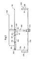
- the plane antenna 1 comprises here, in addition to the two essential elements that are the radiating plate 100 and the coaxial cable 400, a reflector 200.
- This reflector 200 makes it possible, on the one hand, to concentrate the digital radio signals on the radiating plate 100, and, on the other hand, to reduce the echo phenomena. With this reflector 200, the directivity of the plane antenna 1 is substantially increased, so that it has a gain of about 3 dB higher than a planar antenna that would be devoid of this reflector.
- the reflector 200 comprises a rectangular plane base 210, which is positioned parallel and remote from the radiating plate 100. This plane base 210 is thus positioned at the rear of the radiating plate 100 to form a ground plane favoring the ratio before rear of the plane antenna 1.
- the flat base 210 of the reflector 200 is preferably positioned at a distance D2 from the radiating plate 100 which is between 50 and 100 millimeters and which is here equal to 70 millimeters.
- This flat base 210 of the reflector has a height H7 and a width L7 greater than or equal to the total height H6 and total width L6 of the radiating plate 100.
- the dimensions of the base 210 are more precisely from a compromise between the size of the planar antenna 1 and the performance of the reflector 200.
- the widths L7 and height H7 of the plane base 210 are chosen to be 10 mm greater than the total height H6 and total width L6 of the radiating plate 100, so that as seen from the front as shown in FIG. figure 1 , the plane base 210 of the reflector 200 projects one-half centimeter on each side of the radiating plate 100.
- the flat base 210 of the reflector 200 has two rectangular flanges 220, 230 which extend from the two small opposite sides of the flat base 210, perpendicularly thereto, towards the radiating plate 100.
- These two edges 220, 230 thus extend orthogonally to the plane of polarization of the radiating plate 100. They optimize the performance of the reflector without increasing the size of the antenna.
- these two edges 220, 230 extend in length over the entire height H7 of the flat base 210 of the reflector 200. They also extend towards the radiating plate 100 over a distance D3, D4 lower or equal to half the distance D2 separating the radiating plate 100 from the plane base 210 of the reflector 200, so as not to degrade the impedance of the plane antenna 1.
- this distance D3, D4 is equal to 30 millimeters.
- the reflector 200 is derived from a cutting and folding operation of a copper or aluminum metal strip, so that its manufacturing cost is reduced.
- the plane antenna 1 comprises at least one director 300 positioned parallel to the radiating plate 100, in front of the latter.
- Such a director 300 makes it possible to increase the gain of the plane antenna 1 in the high frequencies to which it radiates.
- the plane antenna 1 here comprises a single director 300 positioned at a distance D5 from the radiating plate 100.
- This distance D5 is greater than 20 millimeters for the antenna to remain in a transmission and reception frequency band which covers the TNT type signals.
- the plane antenna 1 comprises a greater number of directors, for example two or three, superimposed parallel and at a distance from each other.
- This director 300 here has the shape of a rectangular plate of height and width less than the height and width of the support portion 110 of the radiating plate 100. It more particularly has a height H11 of between 2 and 10 millimeters, here equal at 8 millimeters, and a width L11 of between 100 and 200 millimeters, here equal to 150 millimeters.
- This director 300 is, like the radiating plate 100 and the reflector 200, obtained by cutting a metal strip of copper or aluminum, so that the total manufacturing cost of the planar antenna 1 is limited.
- the director has a different shape, for example a tubular shape with a diameter of between 2 and 10 millimeters.
- the radiating plate 100 and the reflector 200 are held in a fixed position and parallel to one another.
- This box thus makes it possible not only to protect the radiating plate 100 and the reflector 200, but also to ensure perfect parallelism between these two elements.
- the box is here made of a composite material based on wood to be less polluting than a plastic box, and therefore more easily recyclable.
- the director is arranged to emerge at the front of the box. It is for this purpose maintained parallel to the radiating plate 100 by a rigid foot 310, conductive or not, which extends between the front face of the support portion 110 of the radiating plate 100 and the rear face of the director 300, through an opening in the box.
- the box only acts as a protective member of the planar antenna 1, in which case the radiating plate 100 and the reflector 200 will be held parallel and at a distance from each other by spacers. in the form of a rod.
- the circular section coaxial cable can be replaced by a flat-section electrical conduction element.
- the antenna comprises a printed circuit formed of an insulating substrate (for example Bakelite) and at least one conductive track (for example made of copper) extending on one of the faces of the substrate. .
- an insulating substrate for example Bakelite
- at least one conductive track for example made of copper
- the radiating plate is then formed by a thin metallic layer, of identical shape to the radiating plate illustrated on the figure 1 , extending on the other side of the substrate of the printed circuit.
- the insulating substrate carries, on one of its two faces, the radiating plate, and on the other of its two faces, the conductive track.
- the electrical conduction element is partly formed by this conductive track.
- This electrical conduction element more precisely comprises, on the one hand, an electrical wire connected to the support part of the radiating plate at a point situated on the vertical axis of symmetry A1 of the antenna, and, on the other hand , said conductive track.
- This track then extends on the substrate in a path substantially identical to that of the coaxial cable shown in FIG. figure 1 , with a first portion extending along the support portion of the radiating plate, on the opposite side of the substrate, and a second portion extending along one of the wings of the radiating plate, on the opposite side of the substrate, along the axis of horizontal symmetry A2 of the wing.
- This track here has a width substantially equal to 3 millimeters, to 20%. It thus presents an optimal impedance adaptation.
- the end of this track extends at a distance D1 from the third slot of the radiating plate, which is between one fifth and one half of the width of the corresponding wing of the radiating plate.
- This end is extended by a wire of reduced diameter, of the order of 0.3 millimeters, which extends beyond the third slot and which is connected to the other wing of the radiating plate, via a hole made in the substrate of the printed circuit.
- the thickness and the material of the substrate are chosen here so that the electrical conductor has a characteristic impedance of 75 Ohm.
- This particularly flat antenna is preferably devoid of reflector and director, to have a particularly low thickness.
- This antenna may further comprise a protective envelope molded on the printed circuit, so as to be easily transportable.
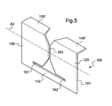
- This radiating plate 100 has a shape close to that of the radiating plate illustrated on the figure 1 . It comes in effect from a flat plate of equal width, to 20%, to 200 millimeters and height equal to 20%, 100 millimeters. It is cut in three slots 161, 162, 163 T, so as to delimit a support portion 110 and two wings 120, 130 which each have an axis of symmetry A2.
- the wings of the radiating plate 100 extending on their edge opposite the support portion 110, by flaps 140 ', 150' which are folded at right angles to the plane of the wings 120, 130.
- the directivity of the antenna is slightly reduced compared with that illustrated in FIG. figure 1 (The gain of this antenna is about 0.3 dB less than that of this antenna), but its size is much lower.
Landscapes
- Aerials With Secondary Devices (AREA)
- Waveguide Aerials (AREA)
- Variable-Direction Aerials And Aerial Arrays (AREA)
- Details Of Aerials (AREA)
Claims (15)
- Antenne (1) mit:- einer ebenen oder zusammengefalteten Strahlplatte (100), in die drei T-förmige Schlitze (161, 162, 163) eingearbeitet sind, wobei ein erster Schlitz (161) und ein zweiter Schlitz (162) das Dach des T bilden und ein dritter Schlitz (163) den Fuß des T bildet, wobei der dritte Schlitz (163) der einzige ist, der in den peripheren Rand (101) der Strahlplatte (100) mündet, wobei diese drei Schlitze (161, 162, 163) zwei Flügel (120, 130) abgrenzen, die auf den zwei Seiten des dritten Schlitzes (163) liegen und zwei gegenüberliegende Endränder (124, 134) aufweisen, die den dritten Schlitz (163) abgrenzen, und- einem elektrischen Leiter (400), der einen ersten, am Endrand (124) eines ersten (120) der beiden Flügel angeschlossenen, elektrischen Leiter (401) umfasst, sowie einen zweiten, vom Endrand (134) eines zweiten (130) der beiden Flügel über mindestens zwei verschiedene Kontaktpunkte (431 - 437) oder über eine durchgehende Kontaktleitung entfernt angeschlossenen elektrischen Leiter (402) umfasst.
- Antenne (1) nach Anspruch 1, mit mindestens einem Direktorelement (300), das parallel zur Ebene der Strahlplatte (100) angeordnet ist.
- Antenne (1) nach einem der Ansprüche 1 und 2, bei der der zweite Flügel (130) eine in der Ebene der Strahlplatte (100) definierte Höhe (H3) und Breite (L3) aufweist und der zweite elektrische Leiter (402) in einer Entfernung (D1) des Endrandes (134) des zweiten Flügels (130) angeschlossen ist, die zwischen einem Fünftel und der Hälfte der Breite (L3) des zweiten Flügels (130) beträgt.
- Antenne (1) nach einem der Ansprüche 1 bis 3, bei der die Strahlplatte (100) in der auseinandergefalteten Form eine Breite aufweist, die mit einer Genauigkeit von 20 % 200 Millimeter beträgt.
- Antenne (1) nach einem der Ansprüche 1 bis 4, bei der die Strahlplatte (100) in der auseinandergefalteten Form eine Höhe (H6) aufweist, die mit einer Genauigkeit von 20 % 100 Millimeter beträgt.
- Antenne (1) nach einem der Ansprüche 1 bis 5, bei der der elektrische Leiter (400) ein koaxiales Kabel mit einer Impedanz von 75 Ohm ist.
- Antenne (1) nach einem der Ansprüche 1 bis 6, bei der sich jeder Flügel (120, 130) entlang einer Symmetrieachse (A2) erstreckt.
- Antenne (1) nach Anspruch 7, bei der der erste und zweite elektrische Leiter (401, 402) jeweils von dieser Symmetrieachse (A2) entfernt an den ersten und zweiten Flügel (120, 130) angeschlossen sind.
- Antenne (1) nach einem der Ansprüche 7 und 8, bei der jeder Flügel (120, 130) einen dem ersten und zweiten Schlitz (161, 162) gegenüberliegenden Rand (122, 132) aufweist, der mit einer Blende (140, 150, 140', 150') ausgestattet ist.
- Antenne (1) nach Anspruch 9, bei der sich jede Blende (140, 150) in der Ebene der Strahlplatte (100) befindet.
- Antenne (1) nach Anspruch 9, bei der jede Blende (140', 150') in einer zur Ebene der Strahlplatte (100) geneigten Ebene zusammengefaltet ist.
- Antenne (1) nach einem der Ansprüche 1 bis 11, bei der sich der erste und zweite Schlitz (162, 163) der Länge nach bis zu einer Entfernung (L4, L5) von 5 bis 65 Millimeter zum peripheren Rand (101) der Strahlptatte (100) erstrecken.
- Antenne (1) nach einem der Ansprüche 1 bis 12 mit einem Reflektor (200), der eine ebene Grundfläche (210) umfasst, die parallel zur Ebene der Strahlplatte (100) angeordnet ist, deren Höhe (H7) und Breite (L7) größer gleich der Höhe (H6) und Breite (L6) der Strahlplatte (100) sind.
- Antenne (1) nach Anspruch 13, bei der die ebene Grundfläche (210) des Reflektors (200) von zwei Rändern (220, 230) eingefasst ist, die sich in einer Entfernung (D3, D4) in Richtung der Strahlplatte (100) erstrecken, die kleiner gleich der Hälfte der Entfernung (D2) ist, welche die Strahlplatte (100) von der ebenen Grundfläche (210) des Reflektors (200) trennt.
- Antenne (1) nach einem der Ansprüche 1 bis 14, bei der sich die Strahlplatte auf einer der Seiten eines Substrats einer Leiterplatte erstreckt und bei der mindestens einer der elektrischen Leiter durch eine Leiterbahn gebildet wird, die sich auf der anderen Seite dieses Substrats erstreckt.
Applications Claiming Priority (2)
| Application Number | Priority Date | Filing Date | Title |
|---|---|---|---|
| FR1000472A FR2956251B1 (fr) | 2010-02-05 | 2010-02-05 | Antenne plane a doublet replie |
| PCT/FR2011/000071 WO2011095712A1 (fr) | 2010-02-05 | 2011-02-04 | Antenne plane à doublet replié |
Publications (2)
| Publication Number | Publication Date |
|---|---|
| EP2532049A1 EP2532049A1 (de) | 2012-12-12 |
| EP2532049B1 true EP2532049B1 (de) | 2014-08-06 |
Family
ID=42735251
Family Applications (1)
| Application Number | Title | Priority Date | Filing Date |
|---|---|---|---|
| EP11708903.7A Not-in-force EP2532049B1 (de) | 2010-02-05 | 2011-02-04 | Gefaltete zweipolige planarantenne |
Country Status (7)
| Country | Link |
|---|---|
| US (1) | US20120299790A1 (de) |
| EP (1) | EP2532049B1 (de) |
| BR (1) | BR112012018455A2 (de) |
| ES (1) | ES2523224T3 (de) |
| FR (1) | FR2956251B1 (de) |
| PT (1) | PT2532049E (de) |
| WO (1) | WO2011095712A1 (de) |
Families Citing this family (6)
| Publication number | Priority date | Publication date | Assignee | Title |
|---|---|---|---|---|
| US20150263427A1 (en) * | 2014-03-12 | 2015-09-17 | Cambridge Silicon Radio Limited | Antenna |
| CN107078383B (zh) * | 2014-10-24 | 2020-01-03 | 华为技术有限公司 | 用于基站天线系统的天线设备 |
| CN105161830B (zh) * | 2015-10-14 | 2017-11-03 | 苏州大学 | 一种宽带领结形对称折合振子天线 |
| US10998636B2 (en) | 2016-04-05 | 2021-05-04 | Nokia Shanghai Bell Co., Ltd | Broadband cavity-backed slot antenna |
| WO2017174900A1 (fr) | 2016-04-08 | 2017-10-12 | Khamprasith Bounpraseuth | Boite pour terminal de communication mobile |
| FR3050077B1 (fr) * | 2016-04-08 | 2019-07-26 | Khamprasith Bounpraseuth | Antenne plane |
Family Cites Families (11)
| Publication number | Priority date | Publication date | Assignee | Title |
|---|---|---|---|---|
| US3074064A (en) * | 1960-02-24 | 1963-01-15 | Pickles Sidney | Self-supporting dipole antenna with balanced-to-unbalanced transformer |
| FR2298200A1 (fr) * | 1975-01-17 | 1976-08-13 | France Etat | Doublet replie epais accordable dans une bande de frequence de deux octaves |
| US5539414A (en) * | 1993-09-02 | 1996-07-23 | Inmarsat | Folded dipole microstrip antenna |
| US6317099B1 (en) * | 2000-01-10 | 2001-11-13 | Andrew Corporation | Folded dipole antenna |
| NZ504042A (en) * | 2000-04-14 | 2002-12-20 | Gregory Daniel Hall | A wide-band high-gain plate dipole antenna using a pair of plate elements arranged in the same plane |
| FR2841688B1 (fr) | 2002-06-28 | 2006-06-30 | Antennes Ft | Antenne plane du type patch, notamment pour l'emission et/ou la reception de signaux de television terrestre numerique et/ou analogique |
| WO2005041355A1 (ja) * | 2003-10-27 | 2005-05-06 | Murata Manufacturing.Co., Ltd. | 折り返しアンテナおよびそれを備えた通信機 |
| JP5016790B2 (ja) * | 2005-05-12 | 2012-09-05 | 株式会社フジクラ | アンテナ |
| JP4712550B2 (ja) * | 2005-06-21 | 2011-06-29 | Dxアンテナ株式会社 | アンテナ装置 |
| JP2010016460A (ja) * | 2008-07-01 | 2010-01-21 | Dx Antenna Co Ltd | 八木形アンテナ |
| JP4431632B2 (ja) * | 2009-02-20 | 2010-03-17 | 八木アンテナ株式会社 | Uhf帯アンテナ |
-
2010
- 2010-02-05 FR FR1000472A patent/FR2956251B1/fr not_active Expired - Fee Related
-
2011
- 2011-02-04 EP EP11708903.7A patent/EP2532049B1/de not_active Not-in-force
- 2011-02-04 WO PCT/FR2011/000071 patent/WO2011095712A1/fr not_active Ceased
- 2011-02-04 BR BR112012018455A patent/BR112012018455A2/pt not_active IP Right Cessation
- 2011-02-04 PT PT117089037T patent/PT2532049E/pt unknown
- 2011-02-04 US US13/576,244 patent/US20120299790A1/en not_active Abandoned
- 2011-02-04 ES ES11708903.7T patent/ES2523224T3/es active Active
Also Published As
| Publication number | Publication date |
|---|---|
| FR2956251B1 (fr) | 2012-12-28 |
| BR112012018455A2 (pt) | 2016-04-19 |
| PT2532049E (pt) | 2014-11-11 |
| US20120299790A1 (en) | 2012-11-29 |
| FR2956251A1 (fr) | 2011-08-12 |
| ES2523224T3 (es) | 2014-11-24 |
| EP2532049A1 (de) | 2012-12-12 |
| WO2011095712A1 (fr) | 2011-08-11 |
Similar Documents
| Publication | Publication Date | Title |
|---|---|---|
| EP2532049B1 (de) | Gefaltete zweipolige planarantenne | |
| EP2058901B1 (de) | Antenne mit reflektierender Störstelle | |
| EP0205212B1 (de) | Modulare Mikrowellenantenneneinheiten und Antenne mit solchen Einheiten | |
| EP0899814B1 (de) | Strahlende Struktur | |
| FR2752646A1 (fr) | Antenne imprimee plane a elements superposes court-circuites | |
| EP3189557B1 (de) | Antenne mit mechanisch umkonfigurierbarem strahlungsmuster | |
| FR2860927A1 (fr) | Antenne interne de faible volume | |
| EP1042845B1 (de) | Antenne | |
| EP0098192B1 (de) | Multiplexanordnung zum Zusammenfügen von zwei Frequenzbändern | |
| EP2416449A1 (de) | Parabolantenne | |
| EP3235058B1 (de) | Drahtplattenantenne mit einem kapazitiven dach mit einem schlitz zwischen der speisungssonde und dem kurzschlussdraht | |
| EP1516393B1 (de) | Doppelpolarisations-doppelbandstrahlungseinrichtung | |
| EP1181744B1 (de) | Antenne mit vertikaler polarisation | |
| FR2950745A1 (fr) | Element rayonnant d'antenne a double polarisation | |
| EP1518296B1 (de) | Mehrband-planarantenne | |
| WO2008125662A1 (fr) | Antenne a éléments rayonnants inclines | |
| EP2432072B1 (de) | Breitband-Symmetrieüberträger auf mehrlagigem Schaltkreis für eine Netzantenne | |
| WO2006125925A1 (fr) | Antenne monopole | |
| EP3547449B1 (de) | Drahtlose kommunikationsvorrichtung, die eine mehrzahl von hornantennen auf einer leiterplatte (pcb) umfasst, entsprechendes herstellungs- und verwendungsverfahren | |
| EP2879233A1 (de) | Integrierte Funkantenne mit Windungen | |
| FR3050077B1 (fr) | Antenne plane | |
| EP0082053B1 (de) | Strahlungssystem mit zwei im selben Frequenzbereich arbeitenden übereinander angebrachten Antennen | |
| WO2016139403A1 (fr) | Structure antennaire omnidirectionnelle large bande | |
| FR2677493A1 (fr) | Reseau d'elements rayonnants a topologie autocomplementaire, et antenne utilisant un tel reseau. | |
| FR3007213A1 (fr) | Procede pour radioelectrifier un objet installe dans un espace public et objet ainsi radioelectrifie. |
Legal Events
| Date | Code | Title | Description |
|---|---|---|---|
| PUAI | Public reference made under article 153(3) epc to a published international application that has entered the european phase |
Free format text: ORIGINAL CODE: 0009012 |
|
| 17P | Request for examination filed |
Effective date: 20120830 |
|
| AK | Designated contracting states |
Kind code of ref document: A1 Designated state(s): AL AT BE BG CH CY CZ DE DK EE ES FI FR GB GR HR HU IE IS IT LI LT LU LV MC MK MT NL NO PL PT RO RS SE SI SK SM TR |
|
| DAX | Request for extension of the european patent (deleted) | ||
| GRAP | Despatch of communication of intention to grant a patent |
Free format text: ORIGINAL CODE: EPIDOSNIGR1 |
|
| INTG | Intention to grant announced |
Effective date: 20140417 |
|
| GRAS | Grant fee paid |
Free format text: ORIGINAL CODE: EPIDOSNIGR3 |
|
| GRAA | (expected) grant |
Free format text: ORIGINAL CODE: 0009210 |
|
| AK | Designated contracting states |
Kind code of ref document: B1 Designated state(s): AL AT BE BG CH CY CZ DE DK EE ES FI FR GB GR HR HU IE IS IT LI LT LU LV MC MK MT NL NO PL PT RO RS SE SI SK SM TR |
|
| REG | Reference to a national code |
Ref country code: GB Ref legal event code: FG4D Free format text: NOT ENGLISH |
|
| REG | Reference to a national code |
Ref country code: CH Ref legal event code: EP Ref country code: AT Ref legal event code: REF Ref document number: 681404 Country of ref document: AT Kind code of ref document: T Effective date: 20140815 |
|
| REG | Reference to a national code |
Ref country code: IE Ref legal event code: FG4D Free format text: LANGUAGE OF EP DOCUMENT: FRENCH |
|
| REG | Reference to a national code |
Ref country code: DE Ref legal event code: R096 Ref document number: 602011008888 Country of ref document: DE Effective date: 20140918 |
|
| REG | Reference to a national code |
Ref country code: PT Ref legal event code: SC4A Free format text: AVAILABILITY OF NATIONAL TRANSLATION Effective date: 20141103 |
|
| REG | Reference to a national code |
Ref country code: CH Ref legal event code: NV Representative=s name: KIRKER AND CIE S.A., CH |
|
| REG | Reference to a national code |
Ref country code: ES Ref legal event code: FG2A Ref document number: 2523224 Country of ref document: ES Kind code of ref document: T3 Effective date: 20141124 |
|
| REG | Reference to a national code |
Ref country code: AT Ref legal event code: MK05 Ref document number: 681404 Country of ref document: AT Kind code of ref document: T Effective date: 20140806 |
|
| REG | Reference to a national code |
Ref country code: NL Ref legal event code: VDEP Effective date: 20140806 |
|
| REG | Reference to a national code |
Ref country code: LT Ref legal event code: MG4D |
|
| PG25 | Lapsed in a contracting state [announced via postgrant information from national office to epo] |
Ref country code: GR Free format text: LAPSE BECAUSE OF FAILURE TO SUBMIT A TRANSLATION OF THE DESCRIPTION OR TO PAY THE FEE WITHIN THE PRESCRIBED TIME-LIMIT Effective date: 20141107 Ref country code: SE Free format text: LAPSE BECAUSE OF FAILURE TO SUBMIT A TRANSLATION OF THE DESCRIPTION OR TO PAY THE FEE WITHIN THE PRESCRIBED TIME-LIMIT Effective date: 20140806 Ref country code: BG Free format text: LAPSE BECAUSE OF FAILURE TO SUBMIT A TRANSLATION OF THE DESCRIPTION OR TO PAY THE FEE WITHIN THE PRESCRIBED TIME-LIMIT Effective date: 20141106 Ref country code: NO Free format text: LAPSE BECAUSE OF FAILURE TO SUBMIT A TRANSLATION OF THE DESCRIPTION OR TO PAY THE FEE WITHIN THE PRESCRIBED TIME-LIMIT Effective date: 20141106 Ref country code: LT Free format text: LAPSE BECAUSE OF FAILURE TO SUBMIT A TRANSLATION OF THE DESCRIPTION OR TO PAY THE FEE WITHIN THE PRESCRIBED TIME-LIMIT Effective date: 20140806 Ref country code: FI Free format text: LAPSE BECAUSE OF FAILURE TO SUBMIT A TRANSLATION OF THE DESCRIPTION OR TO PAY THE FEE WITHIN THE PRESCRIBED TIME-LIMIT Effective date: 20140806 |
|
| PG25 | Lapsed in a contracting state [announced via postgrant information from national office to epo] |
Ref country code: HR Free format text: LAPSE BECAUSE OF FAILURE TO SUBMIT A TRANSLATION OF THE DESCRIPTION OR TO PAY THE FEE WITHIN THE PRESCRIBED TIME-LIMIT Effective date: 20140806 Ref country code: PL Free format text: LAPSE BECAUSE OF FAILURE TO SUBMIT A TRANSLATION OF THE DESCRIPTION OR TO PAY THE FEE WITHIN THE PRESCRIBED TIME-LIMIT Effective date: 20140806 Ref country code: IS Free format text: LAPSE BECAUSE OF FAILURE TO SUBMIT A TRANSLATION OF THE DESCRIPTION OR TO PAY THE FEE WITHIN THE PRESCRIBED TIME-LIMIT Effective date: 20141206 Ref country code: NL Free format text: LAPSE BECAUSE OF FAILURE TO SUBMIT A TRANSLATION OF THE DESCRIPTION OR TO PAY THE FEE WITHIN THE PRESCRIBED TIME-LIMIT Effective date: 20140806 Ref country code: LV Free format text: LAPSE BECAUSE OF FAILURE TO SUBMIT A TRANSLATION OF THE DESCRIPTION OR TO PAY THE FEE WITHIN THE PRESCRIBED TIME-LIMIT Effective date: 20140806 Ref country code: RS Free format text: LAPSE BECAUSE OF FAILURE TO SUBMIT A TRANSLATION OF THE DESCRIPTION OR TO PAY THE FEE WITHIN THE PRESCRIBED TIME-LIMIT Effective date: 20140806 Ref country code: AT Free format text: LAPSE BECAUSE OF FAILURE TO SUBMIT A TRANSLATION OF THE DESCRIPTION OR TO PAY THE FEE WITHIN THE PRESCRIBED TIME-LIMIT Effective date: 20140806 Ref country code: CY Free format text: LAPSE BECAUSE OF FAILURE TO SUBMIT A TRANSLATION OF THE DESCRIPTION OR TO PAY THE FEE WITHIN THE PRESCRIBED TIME-LIMIT Effective date: 20140806 |
|
| PG25 | Lapsed in a contracting state [announced via postgrant information from national office to epo] |
Ref country code: DK Free format text: LAPSE BECAUSE OF FAILURE TO SUBMIT A TRANSLATION OF THE DESCRIPTION OR TO PAY THE FEE WITHIN THE PRESCRIBED TIME-LIMIT Effective date: 20140806 Ref country code: RO Free format text: LAPSE BECAUSE OF FAILURE TO SUBMIT A TRANSLATION OF THE DESCRIPTION OR TO PAY THE FEE WITHIN THE PRESCRIBED TIME-LIMIT Effective date: 20140806 Ref country code: CZ Free format text: LAPSE BECAUSE OF FAILURE TO SUBMIT A TRANSLATION OF THE DESCRIPTION OR TO PAY THE FEE WITHIN THE PRESCRIBED TIME-LIMIT Effective date: 20140806 Ref country code: SK Free format text: LAPSE BECAUSE OF FAILURE TO SUBMIT A TRANSLATION OF THE DESCRIPTION OR TO PAY THE FEE WITHIN THE PRESCRIBED TIME-LIMIT Effective date: 20140806 Ref country code: EE Free format text: LAPSE BECAUSE OF FAILURE TO SUBMIT A TRANSLATION OF THE DESCRIPTION OR TO PAY THE FEE WITHIN THE PRESCRIBED TIME-LIMIT Effective date: 20140806 |
|
| REG | Reference to a national code |
Ref country code: DE Ref legal event code: R097 Ref document number: 602011008888 Country of ref document: DE |
|
| PLBE | No opposition filed within time limit |
Free format text: ORIGINAL CODE: 0009261 |
|
| STAA | Information on the status of an ep patent application or granted ep patent |
Free format text: STATUS: NO OPPOSITION FILED WITHIN TIME LIMIT |
|
| PG25 | Lapsed in a contracting state [announced via postgrant information from national office to epo] |
Ref country code: BE Free format text: LAPSE BECAUSE OF NON-PAYMENT OF DUE FEES Effective date: 20150228 |
|
| 26N | No opposition filed |
Effective date: 20150507 |
|
| PG25 | Lapsed in a contracting state [announced via postgrant information from national office to epo] |
Ref country code: MC Free format text: LAPSE BECAUSE OF FAILURE TO SUBMIT A TRANSLATION OF THE DESCRIPTION OR TO PAY THE FEE WITHIN THE PRESCRIBED TIME-LIMIT Effective date: 20140806 |
|
| REG | Reference to a national code |
Ref country code: IE Ref legal event code: MM4A |
|
| PG25 | Lapsed in a contracting state [announced via postgrant information from national office to epo] |
Ref country code: SI Free format text: LAPSE BECAUSE OF FAILURE TO SUBMIT A TRANSLATION OF THE DESCRIPTION OR TO PAY THE FEE WITHIN THE PRESCRIBED TIME-LIMIT Effective date: 20140806 |
|
| REG | Reference to a national code |
Ref country code: FR Ref legal event code: PLFP Year of fee payment: 6 |
|
| PG25 | Lapsed in a contracting state [announced via postgrant information from national office to epo] |
Ref country code: IE Free format text: LAPSE BECAUSE OF NON-PAYMENT OF DUE FEES Effective date: 20150204 |
|
| PGFP | Annual fee paid to national office [announced via postgrant information from national office to epo] |
Ref country code: LU Payment date: 20160224 Year of fee payment: 6 |
|
| PGFP | Annual fee paid to national office [announced via postgrant information from national office to epo] |
Ref country code: IT Payment date: 20160127 Year of fee payment: 6 Ref country code: DE Payment date: 20160119 Year of fee payment: 6 Ref country code: TR Payment date: 20160106 Year of fee payment: 6 Ref country code: CH Payment date: 20160229 Year of fee payment: 6 Ref country code: ES Payment date: 20160129 Year of fee payment: 6 |
|
| PGFP | Annual fee paid to national office [announced via postgrant information from national office to epo] |
Ref country code: GB Payment date: 20160115 Year of fee payment: 6 Ref country code: PT Payment date: 20160104 Year of fee payment: 6 |
|
| PG25 | Lapsed in a contracting state [announced via postgrant information from national office to epo] |
Ref country code: MT Free format text: LAPSE BECAUSE OF FAILURE TO SUBMIT A TRANSLATION OF THE DESCRIPTION OR TO PAY THE FEE WITHIN THE PRESCRIBED TIME-LIMIT Effective date: 20140806 |
|
| REG | Reference to a national code |
Ref country code: FR Ref legal event code: PLFP Year of fee payment: 7 |
|
| PG25 | Lapsed in a contracting state [announced via postgrant information from national office to epo] |
Ref country code: SM Free format text: LAPSE BECAUSE OF FAILURE TO SUBMIT A TRANSLATION OF THE DESCRIPTION OR TO PAY THE FEE WITHIN THE PRESCRIBED TIME-LIMIT Effective date: 20140806 Ref country code: HU Free format text: LAPSE BECAUSE OF FAILURE TO SUBMIT A TRANSLATION OF THE DESCRIPTION OR TO PAY THE FEE WITHIN THE PRESCRIBED TIME-LIMIT; INVALID AB INITIO Effective date: 20110204 |
|
| REG | Reference to a national code |
Ref country code: DE Ref legal event code: R119 Ref document number: 602011008888 Country of ref document: DE |
|
| REG | Reference to a national code |
Ref country code: CH Ref legal event code: PL |
|
| GBPC | Gb: european patent ceased through non-payment of renewal fee |
Effective date: 20170204 |
|
| PG25 | Lapsed in a contracting state [announced via postgrant information from national office to epo] |
Ref country code: CH Free format text: LAPSE BECAUSE OF NON-PAYMENT OF DUE FEES Effective date: 20170228 Ref country code: LI Free format text: LAPSE BECAUSE OF NON-PAYMENT OF DUE FEES Effective date: 20170228 |
|
| PG25 | Lapsed in a contracting state [announced via postgrant information from national office to epo] |
Ref country code: PT Free format text: LAPSE BECAUSE OF NON-PAYMENT OF DUE FEES Effective date: 20170804 |
|
| PG25 | Lapsed in a contracting state [announced via postgrant information from national office to epo] |
Ref country code: LU Free format text: LAPSE BECAUSE OF NON-PAYMENT OF DUE FEES Effective date: 20170204 |
|
| PG25 | Lapsed in a contracting state [announced via postgrant information from national office to epo] |
Ref country code: DE Free format text: LAPSE BECAUSE OF NON-PAYMENT OF DUE FEES Effective date: 20170901 |
|
| REG | Reference to a national code |
Ref country code: FR Ref legal event code: PLFP Year of fee payment: 8 |
|
| PG25 | Lapsed in a contracting state [announced via postgrant information from national office to epo] |
Ref country code: IT Free format text: LAPSE BECAUSE OF NON-PAYMENT OF DUE FEES Effective date: 20170204 Ref country code: GB Free format text: LAPSE BECAUSE OF NON-PAYMENT OF DUE FEES Effective date: 20170204 |
|
| PG25 | Lapsed in a contracting state [announced via postgrant information from national office to epo] |
Ref country code: MK Free format text: LAPSE BECAUSE OF FAILURE TO SUBMIT A TRANSLATION OF THE DESCRIPTION OR TO PAY THE FEE WITHIN THE PRESCRIBED TIME-LIMIT Effective date: 20140806 |
|
| REG | Reference to a national code |
Ref country code: ES Ref legal event code: FD2A Effective date: 20180705 |
|
| PG25 | Lapsed in a contracting state [announced via postgrant information from national office to epo] |
Ref country code: ES Free format text: LAPSE BECAUSE OF NON-PAYMENT OF DUE FEES Effective date: 20170205 |
|
| PG25 | Lapsed in a contracting state [announced via postgrant information from national office to epo] |
Ref country code: AL Free format text: LAPSE BECAUSE OF FAILURE TO SUBMIT A TRANSLATION OF THE DESCRIPTION OR TO PAY THE FEE WITHIN THE PRESCRIBED TIME-LIMIT Effective date: 20140806 |
|
| PGFP | Annual fee paid to national office [announced via postgrant information from national office to epo] |
Ref country code: FR Payment date: 20230228 Year of fee payment: 13 |
|
| PG25 | Lapsed in a contracting state [announced via postgrant information from national office to epo] |
Ref country code: TR Free format text: LAPSE BECAUSE OF NON-PAYMENT OF DUE FEES Effective date: 20170204 |
|
| PG25 | Lapsed in a contracting state [announced via postgrant information from national office to epo] |
Ref country code: FR Free format text: LAPSE BECAUSE OF NON-PAYMENT OF DUE FEES Effective date: 20240229 |
|
| PG25 | Lapsed in a contracting state [announced via postgrant information from national office to epo] |
Ref country code: FR Free format text: LAPSE BECAUSE OF NON-PAYMENT OF DUE FEES Effective date: 20240229 |