EP2528094B1 - Halbleiterstrommodul, stromumwandlungsvorrichtung und schienenfahrzeug - Google Patents
Halbleiterstrommodul, stromumwandlungsvorrichtung und schienenfahrzeug Download PDFInfo
- Publication number
- EP2528094B1 EP2528094B1 EP10843063.8A EP10843063A EP2528094B1 EP 2528094 B1 EP2528094 B1 EP 2528094B1 EP 10843063 A EP10843063 A EP 10843063A EP 2528094 B1 EP2528094 B1 EP 2528094B1
- Authority
- EP
- European Patent Office
- Prior art keywords
- module
- fwd
- igbt
- power
- converting apparatus
- Prior art date
- Legal status (The legal status is an assumption and is not a legal conclusion. Google has not performed a legal analysis and makes no representation as to the accuracy of the status listed.)
- Active
Links
Images


Classifications
-
- H—ELECTRICITY
- H02—GENERATION; CONVERSION OR DISTRIBUTION OF ELECTRIC POWER
- H02M—APPARATUS FOR CONVERSION BETWEEN AC AND AC, BETWEEN AC AND DC, OR BETWEEN DC AND DC, AND FOR USE WITH MAINS OR SIMILAR POWER SUPPLY SYSTEMS; CONVERSION OF DC OR AC INPUT POWER INTO SURGE OUTPUT POWER; CONTROL OR REGULATION THEREOF
- H02M7/00—Conversion of AC power input into DC power output; Conversion of DC power input into AC power output
- H02M7/003—Constructional details, e.g. physical layout, assembly, wiring or busbar connections
-
- B—PERFORMING OPERATIONS; TRANSPORTING
- B60—VEHICLES IN GENERAL
- B60L—PROPULSION OF ELECTRICALLY-PROPELLED VEHICLES; SUPPLYING ELECTRIC POWER FOR AUXILIARY EQUIPMENT OF ELECTRICALLY-PROPELLED VEHICLES; ELECTRODYNAMIC BRAKE SYSTEMS FOR VEHICLES IN GENERAL; MAGNETIC SUSPENSION OR LEVITATION FOR VEHICLES; MONITORING OPERATING VARIABLES OF ELECTRICALLY-PROPELLED VEHICLES; ELECTRIC SAFETY DEVICES FOR ELECTRICALLY-PROPELLED VEHICLES
- B60L15/00—Methods, circuits, or devices for controlling the traction-motor speed of electrically-propelled vehicles
- B60L15/007—Physical arrangements or structures of drive train converters specially adapted for the propulsion motors of electric vehicles
-
- B—PERFORMING OPERATIONS; TRANSPORTING
- B60—VEHICLES IN GENERAL
- B60L—PROPULSION OF ELECTRICALLY-PROPELLED VEHICLES; SUPPLYING ELECTRIC POWER FOR AUXILIARY EQUIPMENT OF ELECTRICALLY-PROPELLED VEHICLES; ELECTRODYNAMIC BRAKE SYSTEMS FOR VEHICLES IN GENERAL; MAGNETIC SUSPENSION OR LEVITATION FOR VEHICLES; MONITORING OPERATING VARIABLES OF ELECTRICALLY-PROPELLED VEHICLES; ELECTRIC SAFETY DEVICES FOR ELECTRICALLY-PROPELLED VEHICLES
- B60L3/00—Electric devices on electrically-propelled vehicles for safety purposes; Monitoring operating variables, e.g. speed, deceleration or energy consumption
- B60L3/0023—Detecting, eliminating, remedying or compensating for drive train abnormalities, e.g. failures within the drive train
- B60L3/003—Detecting, eliminating, remedying or compensating for drive train abnormalities, e.g. failures within the drive train relating to inverters
-
- B—PERFORMING OPERATIONS; TRANSPORTING
- B60—VEHICLES IN GENERAL
- B60L—PROPULSION OF ELECTRICALLY-PROPELLED VEHICLES; SUPPLYING ELECTRIC POWER FOR AUXILIARY EQUIPMENT OF ELECTRICALLY-PROPELLED VEHICLES; ELECTRODYNAMIC BRAKE SYSTEMS FOR VEHICLES IN GENERAL; MAGNETIC SUSPENSION OR LEVITATION FOR VEHICLES; MONITORING OPERATING VARIABLES OF ELECTRICALLY-PROPELLED VEHICLES; ELECTRIC SAFETY DEVICES FOR ELECTRICALLY-PROPELLED VEHICLES
- B60L50/00—Electric propulsion with power supplied within the vehicle
- B60L50/50—Electric propulsion with power supplied within the vehicle using propulsion power supplied by batteries or fuel cells
- B60L50/51—Electric propulsion with power supplied within the vehicle using propulsion power supplied by batteries or fuel cells characterised by AC-motors
-
- B—PERFORMING OPERATIONS; TRANSPORTING
- B60—VEHICLES IN GENERAL
- B60L—PROPULSION OF ELECTRICALLY-PROPELLED VEHICLES; SUPPLYING ELECTRIC POWER FOR AUXILIARY EQUIPMENT OF ELECTRICALLY-PROPELLED VEHICLES; ELECTRODYNAMIC BRAKE SYSTEMS FOR VEHICLES IN GENERAL; MAGNETIC SUSPENSION OR LEVITATION FOR VEHICLES; MONITORING OPERATING VARIABLES OF ELECTRICALLY-PROPELLED VEHICLES; ELECTRIC SAFETY DEVICES FOR ELECTRICALLY-PROPELLED VEHICLES
- B60L7/00—Electrodynamic brake systems for vehicles in general
- B60L7/10—Dynamic electric regenerative braking
- B60L7/14—Dynamic electric regenerative braking for vehicles propelled by AC motors
-
- H—ELECTRICITY
- H10—SEMICONDUCTOR DEVICES; ELECTRIC SOLID-STATE DEVICES NOT OTHERWISE PROVIDED FOR
- H10W—GENERIC PACKAGES, INTERCONNECTIONS, CONNECTORS OR OTHER CONSTRUCTIONAL DETAILS OF DEVICES COVERED BY CLASS H10
- H10W90/00—Package configurations
-
- B—PERFORMING OPERATIONS; TRANSPORTING
- B60—VEHICLES IN GENERAL
- B60L—PROPULSION OF ELECTRICALLY-PROPELLED VEHICLES; SUPPLYING ELECTRIC POWER FOR AUXILIARY EQUIPMENT OF ELECTRICALLY-PROPELLED VEHICLES; ELECTRODYNAMIC BRAKE SYSTEMS FOR VEHICLES IN GENERAL; MAGNETIC SUSPENSION OR LEVITATION FOR VEHICLES; MONITORING OPERATING VARIABLES OF ELECTRICALLY-PROPELLED VEHICLES; ELECTRIC SAFETY DEVICES FOR ELECTRICALLY-PROPELLED VEHICLES
- B60L2200/00—Type of vehicles
- B60L2200/26—Rail vehicles
-
- Y—GENERAL TAGGING OF NEW TECHNOLOGICAL DEVELOPMENTS; GENERAL TAGGING OF CROSS-SECTIONAL TECHNOLOGIES SPANNING OVER SEVERAL SECTIONS OF THE IPC; TECHNICAL SUBJECTS COVERED BY FORMER USPC CROSS-REFERENCE ART COLLECTIONS [XRACs] AND DIGESTS
- Y02—TECHNOLOGIES OR APPLICATIONS FOR MITIGATION OR ADAPTATION AGAINST CLIMATE CHANGE
- Y02T—CLIMATE CHANGE MITIGATION TECHNOLOGIES RELATED TO TRANSPORTATION
- Y02T10/00—Road transport of goods or passengers
- Y02T10/60—Other road transportation technologies with climate change mitigation effect
- Y02T10/64—Electric machine technologies in electromobility
-
- Y—GENERAL TAGGING OF NEW TECHNOLOGICAL DEVELOPMENTS; GENERAL TAGGING OF CROSS-SECTIONAL TECHNOLOGIES SPANNING OVER SEVERAL SECTIONS OF THE IPC; TECHNICAL SUBJECTS COVERED BY FORMER USPC CROSS-REFERENCE ART COLLECTIONS [XRACs] AND DIGESTS
- Y02—TECHNOLOGIES OR APPLICATIONS FOR MITIGATION OR ADAPTATION AGAINST CLIMATE CHANGE
- Y02T—CLIMATE CHANGE MITIGATION TECHNOLOGIES RELATED TO TRANSPORTATION
- Y02T10/00—Road transport of goods or passengers
- Y02T10/60—Other road transportation technologies with climate change mitigation effect
- Y02T10/70—Energy storage systems for electromobility, e.g. batteries
Definitions
- the present invention relates to a power converting apparatus applicable to a railway car and, more particularly, to a power semiconductor module mountable on the power converting apparatus of this type.
- Patent Literature 1 Although not limited to the use in railway cars, as a power semiconductor module applicable to the use for relatively-high output power conversion, there is a power semiconductor module disclosed in Patent Literature 1 mentioned above, for example.
- a configuration is disclosed that includes two sets of element pairs each formed by connecting a switching element called IGBT (Insulated Gate Bipolar Transistor) and a diode element called fry wheel diode (FWD) in anti-parallel to each other.
- IGBT Insulated Gate Bipolar Transistor
- FWD fry wheel diode
- the power semiconductor module is configured as a power semiconductor module of so-called "2-in-1" (see FIGS. 1 to 4 and more of the literature).
- Patent Literature 1 Japanese Patent Application Laid-open No. 2009-059923
- the element pairs constituting a 2-in-1 type power semiconductor module (hereinafter referred to as "2-in-1 module” according to necessity) as mentioned above are connected in series in a module, the element pairs can be used as negative arm elements on a positive side and a negative side in an inverter and a converter. Therefore, for example, a three-phase inverter can be configured by three 2-in-1 modules. This enables reduction in size of the apparatus.
- an electric current and a switching frequency have to be set or controlled such that a bonding temperature for IGBT chips in the power running mode and a bonding temperature for FWD chips in the regenerative mode become equal to or lower than their respective allowable bonding temperatures.
- the present 2-in-1 module it has been difficult to set the electric current and the switching frequency such that the bonding temperature for the FWD chips in the regenerative mode becomes equal to or lower than the allowable bonding temperature.
- the size of the IGBT chips and the size of the FWD chips are in a trade-off relation. Therefore, it is also conceivable to reduce the size of the IGBT chips and allocate the reduction to the FWD chips.
- the chip size of the IGBT is set as small as possible. A further reduction in size exceeds a limit because it is difficult to secure an electric current capacity in the power running mode.
- a power semiconductor module of the same electric current class has to be configured using six power semiconductor modules of so-called “1-in-1” (hereinafter referred to as “1-in-1 modules” according to necessity), in each of which one set of an IGBT and an FWD are mounted. So, it is difficult to further reduce the size of a power converting apparatus.
- a converter circuit having at least one switching device and a diode, made of SiC is disclosed, which is arranged to conduct when the device is turned off and reverse biased when the device is turned on.
- This document discloses a power semiconductor module according to the preamble of claim 1.
- the present invention has been devised in view of the above-mentioned circumstances, and it is an object of the present invention to provide a power semiconductor module that can be further downsized and is applicable to a power converting apparatus for a railway car.
- the present invention which is defined in claim 1, provides a power semiconductor module applied to a power converting apparatus for a railway car, the power semiconductor module comprising: a first element pair formed by connecting a first switching element and a first diode element in anti-parallel to each other; and a second element pair formed by connecting a second switching element and a second diode element in anti-parallel to each other, wherein the first and second diode elements are formed of wideband gap semiconductor; and the first element pair and the second element pair are housed in one module and configured as a 2-in-1 module in a manner that the first element pair operates as a positive side arm of the power converting apparatus and the second element pair operates as a negative side arm of the power converting apparatus.
- the power semiconductor module according to the present invention there is an advantageous effect that it is possible to provide a power semiconductor module of the 2-in-1 type that can use the existing module of the 1-in-1 type without increasing the module size and is applicable to a railway car.
- the inventor of this application focused on an SiC diode that can reduce an ON voltage and, as a result, can substantially reduce a recovery loss.
- the inventor came to derive a power semiconductor module and a power converting apparatus suitable for a railway application by applying the SiC diode to the 2-in-1 module to configure a power converting apparatus.
- a power semiconductor module and a power converting apparatus according to an embodiment of the present invention are described below with reference to the accompanying drawings. The present invention is no limited to the embodiments described below.
- FIG. 1 is a diagram showing a schematic functional configuration of the power converting apparatus according to this embodiment.
- the power converting apparatus 50 includes a converter 10, a capacitor 20 and an inverter 30.
- the railway car 100 is mounted with a transformer 6 that is arranged on an input end side of the power converting apparatus 50 and connected to the converter 10, and a motor 40 that is arranged on an output end side of the power converting apparatus 50, connected to the inverter 30 and receives power supply from the power converting apparatus 50 to drive the car.
- the motor 40 an induction motor or a synchronous motor is suitable.
- One end of a primary winding of the transformer 6 is connected to an overhead line 1 via a current collector 2.
- the other end of the primary winding is connected to a rail 4, which is ground potential, via a wheel 3.
- Electric power supplied from the overhead line 1 is inputted to the primary winding of the transformer 6 via the current collector 2, while electric power generated in a secondary winding of the transformer 6 is inputted to the converter 10.
- the converter 10 includes circuit sections (hereinafter referred to as "legs") in which a positive side arm composed of switching elements UPC and VPC (e.g., for a U phase, UPC) and a negative side arm composed of switching elements UNC and VNC (e.g., for the U phase, UNC) are respectively connected in series.
- a single-phase bridge circuit including two sets (for a U phase and a V phase) of legs is configured.
- the converter 10 subjects the switching elements UPC, VPC, UNC and VNC to PWM control to convert an input alternating-current voltage into a desired direct-current voltage and output the direct-current voltage.
- An output end of the converter 10 is connected to the capacitor 20 functioning as a direct-current power supply in parallel, and connected to the inverter 30 that receives a direct-current voltage of the capacitor 20 as an input, converts the direct-current voltage into an alternating-current voltage having an arbitrary voltage and an arbitrary frequency, and outputs the alternating-current voltage.
- the inverter 30 includes legs in which a positive side arm composed of switching elements UPI, VPI and WPI (e.g., for the U phase, UPI) and a negative side arm composed of switching elements UNI, VNI and WNI (e.g., for the U phase, UNI) are respectively connected in series.
- a three-phase bridge circuit including three sets (for the U phase, the V phase and the W phase) of legs is configured.
- the inverter 30 subjects the switching elements UPI, VPI, WPI, UNI, VNI and WNI to PWM control to convert an input direct-current voltage into a desired alternating-current voltage and outputs the alternating-current voltage.
- FIG. 1 as a preferred example of the power converting apparatus according to this embodiment, there is shown one case where the power converting apparatus is applied to an alternating-current input electric rolling stock.
- the power converting apparatus can also be applied to a direct-current input electric rolling stock frequently used in subways, suburban electric rolling stocks or the like in the same manner.
- the power converting apparatus is applied to the direct-current input electric rolling stock, a configuration equivalent to the configuration shown in FIG. 1 can be adopted except that the configuration of the transformer 6 and the converter 10 is unnecessary. It is naturally possible to apply the contents according to this embodiment to the direct-current input electric rolling stock.
- FIG. 2 is a perspective view showing a schematic shape of a power semiconductor module according to this embodiment configured as a 2-in-1 module.
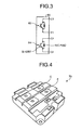
- FIG. 3 is a diagram schematically showing a circuit configuration owned by the power semiconductor module shown in FIG. 2 .
- FIG. 4 is a perspective view showing a schematic shape of a power semiconductor module shown as a comparative example, which is a 1-in-1 module used in the past.
- FIG. 5 is a diagram schematically showing a circuit configuration owned by the power semiconductor module shown in FIG. 4 .
- a silicon-based IGBT (Si-IGBT) and a silicon-based FWD (Si-FWD) are connected in anti-parallel to each other is housed in a package.
- a collector of the Si-IGBT and a cathode of the Si-FWD are connected within the module.
- a connection end of the collector and the cathode is drawn out and connected to a collector electrode C provided on the upper surface of the 1-in-1 module 70.
- an emitter of the Si-IGBT and an anode of the Si-FWD are connected within the module.
- a connection end of the emitter and the anode is drawn out and connected to an emitter electrode E provided on the upper surface of the 1-in-1 module 70.
- a first element pair 62 and a second element pair 64 which are two sets of element pairs, in each of which silicon (Si)-based IGBT (Si-IGBTs) and silicon carbide (SiC)-based FWD (SiC-FWD) are connected in anti-parallel to each other, are housed in a package.
- Silicon carbide is one example of semiconductor called wideband gap semiconductor.
- semiconductor formed using a gallium nitride based material or diamond also belongs to the wideband gap semiconductor. Therefore, a configuration in which other wideband gap semiconductor different from silicon carbide is used may also constitute the gist of the present invention.
- a collector of the Si-IGBT and a cathode of the SiC-FWD are connected within the module.
- a connection end of the collector and the cathode is drawn out and connected to a collector electrode C1 provided on the upper surface of the 2-in-1 module 60.
- An emitter of the Si-IGBT and an anode of the SiC-FWD are connected within the module.
- a connection end of the emitter and the anode is drawn out and connected to an emitter electrode E1 provided on the upper surface of the 2-in-1 module 60.
- a collector of the Si-IGBT and a cathode of the SiC-FWD are connected within the module.
- a connection end of the collector and the cathode is drawn out and connected to a collector electrode C2 provided on the upper surface of the 2-in-1 module 60.
- An emitter of the Si-IGBT and an anode of the SiC-FWD are connected within the module.
- a connection end of the emitter and the anode is drawn out and connected to an emitter electrode E2 provided on the upper surface of the 2-in-1 module 60.
- the power semiconductor module according to this embodiment can be configured as a 2-in-1 module compatibly using a package of the existing 1-in-1 module and without increasing the size of the existing 1-in-1 module is explained.
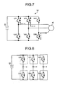
- the motor 40 functions as an electricity generator and an electric current from the motor 40 flows into the positive electrode side of the capacitor 20. Therefore, for example, in a period in which an induced voltage for the U phase and the V phase in the motor 40 is positive and an induced voltage for the W phase is negative, as shown in FIG. 7 , an electric current flows into the capacitor 20 side through the FWDs of the switching elements UPI and VPI, and a return electric current of the electric current returns to the motor 40 through the FWD of the switching element WNI. As a result, during the regenerative mode, the FWDs generate higher heat compared with the IGBTs.
- a heat value of a general-purpose 2-in-1 module is calculated using parameters shown in Table 1 below.
- the 2-in-1 module used herein includes silicon-based IGBTs (Si-IGBTs) and silicon-based FWDs (Si-FWDs).
- Table 1 Parameters of the 2-in-1 module (Si-FWD) (Rated voltage: 1700 V, rated current: 1200 A) IGBT ON voltage during 600 A energization 1.65 V Switching loss during 600 A energization (Loss per one pulse) 0.32 J/P Heat resistance between a bonding section and a case 0.019 K/W Si-FWD ON voltage during 600 A energization 2.1 V Switching loss during 600 A energization (Loss per one pulse) 0.17 J/P Heat resistance between a bonding section and a case 0.042 K/W
- the ON losses of the IGBT and the FWD are calculated by dividing a product of a voltage and an electric current by 2 because it is assumed that an electric current for a half period flows to one IGBT, i.e., one IGBT and one FWD operate only for a half period of one period. The same holds true for the switching losses of the IGBT and the FWD, and so the number of pulses (switching frequency) is divided by 2.
- a cooler is selected to set a case temperature of the module to 110°C such that a bonding temperature for the IGBT becomes equal to or lower than an allowable bonding temperature.
- a cooler adapted to the temperature rise in the FWD is selected.
- a cooler having higher performance is required. Therefore, the size of the cooler increases and a cost of the cooler increases.
- a heat value of a general-purpose 1-in-1 module is calculated using parameters shown in Table 3 below.
- the 1-in-1 module used herein includes a silicon-based IGBT (Si-IGBT) and a silicon-based FWD (Si-FWD).
- the 1-in-1 module has a margin in terms of space compared with the 2-in-1 module, and so it can house one having less diode loss and less heat resistance than those of the FWD shown in Table 1.
- a cooler is selected to set a case temperature of the module to 110°C.
- the temperature rise in the FWD is about twice as large as the temperature rise in the IGBT. Therefore, if the cooler has cooling performance adapted to the temperature rise in the IGBT, then the temperature rise in the FWD exceeds the allowable value. Therefore, the module can not be used for the application. On the contrary, if the cooler has cooling performance adapted to the temperature rise in the FWD, then the size of the cooler increases and a cost of the cooler increases.
- a three-phase inverter is configured using six 1-in-1 modules having a small FWD loss and small heat resistance in order to prevent the size of the cooler from increasing and prevent a cost of the cooler from increasing (see FIG. 8 ).
- FIG. 9 is a diagram showing an arrangement example of one element pair in the 2-in-1 module according to this embodiment configured using the SiC-FWDs.
- FIG. 10 an arrangement example of one element pair in the conventional 2-in-1 module configured using the Si-FWDs is shown as a comparative example.
- the conventional 2-in-1 module is configured using four IGBT chips and two Si-FWD chips per one element pair.
- an occupied area of the Si-FWD chips is about a half (50%) of an occupied area of the IGBT chips.
- the 2-in-1 module according to this embodiment, SiC is used for the FWD, so that it is possible to make an occupied area of the SiC-FWD chips smaller than the occupied area of the conventional Si-FWD chips.
- the 2-in-1 module has a configuration including four IGBT chips and eight SiC FWD chips per one element pair.
- the occupied area of the SiC-FWD chips is about a quarter (25%) of the occupied area of the IGBT chips.
- the ON voltage of the FWD can be reduced, so that the recovery loss can also be substantially reduced.
- chip thickness can also be reduced, so that heat resistance also decreases. For this reason, as shown in FIG. 9 , it is possible to suppress the temperature rise in the FWDs to the same degree as the temperature rise in the IGBT module of the 1-in-1 type without changing the layout of the chips.
- the temperature rise in the SiC-FWD chips is the same degree as the temperature rise in the IGBT chips.
- the temperature rise in the SiC-FWD chips can be reduced to a temperature rise value equal to or smaller than a half of 30°C (see Table 2), which is a temperature rise value of the Si-FWD chips in the conventional 2-in-1 module. Even if a cooler adapted to the temperature rise in the IGBT chips to set a case temperature of the module to 110°C is used, the bonding temperature of the FWD chips can be set to be equal to or lower than 125°C of the bonding temperature allowable value.
- an allowable operating temperature of the SiC-FWD chips can be increased to 150°C or higher and the occupied area of the SiC-FWD chips can be further reduced. Therefore, it is possible to further reduce the module size.
- the performance of the cooler for SiC can be reduced by virtue of increase in the allowable operating temperature of the SiC-FWD chips. Therefore, it is possible to reduce the size and costs of the cooler.
- the significance of the present invention resides in providing a 2-in-1 module applicable to a power converting apparatus for a railway application. Therefore, the FWD chip occupied area ratio can be any value as long as the significance can be realized.
- the characteristic of SiC in that SiC can be used at high temperature is utilized as explained above or the reduction in the occupied area of the SiC-FWD chips is allocated to the IGBT chips is used, it is possible to further reduce the FWD chip occupied area ratio according to a synergistic effect of the reduction in the occupied area of the SiC-FWD chips and the increase in the occupied area of the IGBT chips.
- a reduction effect by the former is estimated as 20% and a reduction effect by the latter is estimated as 20%
- an incidental effect that the chip size of the 2-in-1 module can be reduced is obtained.
- This effect is obtained under the condition that the FWD chip occupied area ratio in the conventional 2-in-1 module can be reduced to be smaller than 1/2 by using SiC for the FWDs.
- the IGBTs are explained as an example of the switching elements for constructing the 2-in-1 module.
- MOSFETs can be mounted instead of the IGBTs. Because the MOSFETs have a switching loss smaller than that of the IGBTs, it is possible to realize reduction in size and reduction in cost of the module and the cooler by use of the MOSFETs.
- the SiC-FWD chips are formed in a size for equalizing the temperature rise in the SiC-FWD chips to the temperature rise in the IGBT chips forming the respective element pairs, the design of the cooler is easy. This is effective for reduction in size and reduction in cost of the cooler.
- the application to the inverter is explained as an example.
- application to a converter is naturally possible.
- the converter in the conventional art, the converter is configured using four 1-in-1 modules.
- the converter can be configured using two 2-in-1 modules.
- an electric current flowing to the FWDs is larger than an electric current flowing to the IGBTs. Therefore, by applying SiC to the FWDs, it is possible to realize reduction in size and reduction in cost of the apparatus through reduction in loss and realize improvement of reliability through reduction in the number of components.
- the present invention is useful for a power semiconductor module and a power converting apparatus that can be a further downsized and are applicable to a railway car.
Landscapes
- Engineering & Computer Science (AREA)
- Power Engineering (AREA)
- Transportation (AREA)
- Mechanical Engineering (AREA)
- Life Sciences & Earth Sciences (AREA)
- Sustainable Development (AREA)
- Sustainable Energy (AREA)
- Inverter Devices (AREA)
- Electric Propulsion And Braking For Vehicles (AREA)
Claims (5)
- Leistungshalbleitermodul (60), das auf eine Energieumwandlungsvorrichtung (50) für ein Schienenfahrzeug (100) angewendet wird, wobei
ein erstes Elementpaar (62) und ein zweites Elementpaar (64) in Reihe geschaltet und in einem Modul (60) untergebracht sind,
das erste Elementpaar (62) gebildet ist, indem ein erstes Schaltelement (IGBT) und ein erstes Diodenelement (SiC-FWD) zueinander antiparallel geschaltet und dazu ausgelegt sind, als ein positivseitiger Zweig der Energieumwandlungsvorrichtung (50) zu wirken, und
das zweite Elementpaar (64) gebildet ist, indem ein zweites Schaltelement (Si-IGBT) und ein zweites Diodenelement (SiC-FWD) zueinander antiparallel geschaltet und dazu ausgelegt sind, als ein negativseitiger Zweig der Energieumwandlungsvorrichtung (50) zu wirken,
das erste Elementpaar (62) und das zweite Elementpaar (64) als ein 2-in-1-Modul (60) ausgelegt sind, in dem ein elektrischer Strom im ersten Schaltelement und zweiten Schaltelement während einer Beschleunigung des Fahrzeugs (100) fließt, und ein elektrischer Strom im ersten Diodenelement und zweiten Diodenelement während eines Abbremsens des Fahrzeugs fließt, wobei das erste und zweite Diodenelement (FWD) aus einem Halbleiter mit großer Bandlücke gebildet sind, dadurch gekennzeichnet, dass:ein Verhältnis eines eingenommenen Bereichs der Diodenelemente (FWD) zu einem eingenommenen Bereich der Schaltelemente (IGBT) in den Elementpaaren (62, 64) gleich oder größer als 15% und kleiner als 45% ist, unddas erste und zweite Diodenelement (FWD) in einer Größe ausgebildet sind, um einen Temperaturanstieg im ersten und zweiten Diodenelement (FWD) an einen Temperaturanstieg im ersten und zweiten Schaltelement (IGBT) anzugleichen. - Leistungshalbleitermodul (60) nach Anspruch 1, wobei es sich bei dem Halbleiter mit großer Bandlücke um einen Halbleiter handelt, der unter Verwendung von Siliciumcarbid, einem Galliumnitridgrundmaterial oder Diamant ausgebildet ist.
- Leistungshalbleitermodul (60) nach Anspruch 1, wobei es sich bei dem ersten und zweiten Schaltelement (IGBT) um IGBT-Elemente oder MOSFET-Elemente handelt.
- Energieumwandlungsvorrichtung (50), die in einem Schienenfahrzeug (100) installiert und dazu ausgelegt ist, eine eingegebene Gleichstromspannung oder Wechselstromspannung in eine gewünschte Wechselstromspannung umzuwandeln und die Wechselstromspannung auszugeben, wobei
die Energieumwandlungsvorrichtung (50) das Leistungshalbleitermodul (60) nach Anspruch 1 enthält,
ein Zweig (UPC, UNC, VPC, VNC) gebildet ist, indem der positivseitige Zweig und der negativseitige Zweig in Reihe geschaltet sind, und
mehrere Zweige (UPC, UNC, VPC, VNC) in einem Modul (60) untergebracht sind. - Schienenfahrzeug (100), Folgendes umfassend:eine Energieumwandlungsvorrichtung (50), die dazu ausgelegt ist, eine eingegebene Gleichstromspannung oder Wechselstromspannung in eine gewünschte Wechselstromspannung umzuwandeln und die Wechselstromspannung auszugeben; undeinen Motor (40), der dazu ausgelegt ist, eine Energieversorgung aus der Energieumwandlungsvorrichtung (50) zu erhalten und das Fahrzeug (100) anzutreiben, wobeidie Energieumwandlungsvorrichtung (50) das Leistungshalbleiterbauteil (60) nach Anspruch 1 enthält,ein Zweig (UPC, UNC, VPC, VNC) gebildet ist, indem der positivseitige Zweig und der negativseitige Zweig in Reihe geschaltet sind, undmehrere Zweige (UPC, UNC, VPC, VNC) in einem Modul (60) untergebracht sind.
Applications Claiming Priority (1)
| Application Number | Priority Date | Filing Date | Title |
|---|---|---|---|
| PCT/JP2010/050512 WO2011086705A1 (ja) | 2010-01-18 | 2010-01-18 | パワー半導体モジュール、電力変換装置および鉄道車両 |
Publications (3)
| Publication Number | Publication Date |
|---|---|
| EP2528094A1 EP2528094A1 (de) | 2012-11-28 |
| EP2528094A4 EP2528094A4 (de) | 2014-03-12 |
| EP2528094B1 true EP2528094B1 (de) | 2015-04-01 |
Family
ID=44304008
Family Applications (1)
| Application Number | Title | Priority Date | Filing Date |
|---|---|---|---|
| EP10843063.8A Active EP2528094B1 (de) | 2010-01-18 | 2010-01-18 | Halbleiterstrommodul, stromumwandlungsvorrichtung und schienenfahrzeug |
Country Status (9)
| Country | Link |
|---|---|
| US (1) | US9520802B2 (de) |
| EP (1) | EP2528094B1 (de) |
| JP (1) | JP4722229B1 (de) |
| KR (1) | KR101387515B1 (de) |
| CN (1) | CN102714203B (de) |
| AU (1) | AU2010342148B2 (de) |
| BR (1) | BR112012016900A2 (de) |
| MX (1) | MX2012008026A (de) |
| WO (1) | WO2011086705A1 (de) |
Families Citing this family (14)
| Publication number | Priority date | Publication date | Assignee | Title |
|---|---|---|---|---|
| JP6007578B2 (ja) * | 2012-05-10 | 2016-10-12 | 富士電機株式会社 | パワー半導体モジュールおよびその組立方法 |
| JP6187819B2 (ja) * | 2013-12-19 | 2017-08-30 | パナソニックIpマネジメント株式会社 | 回路モジュール、電力制御装置及び電力制御回路の製造方法 |
| JP6366612B2 (ja) * | 2014-02-11 | 2018-08-01 | 三菱電機株式会社 | 電力用半導体モジュール |
| JP6384406B2 (ja) * | 2015-06-18 | 2018-09-05 | 株式会社デンソー | 半導体装置 |
| US9997476B2 (en) | 2015-10-30 | 2018-06-12 | Infineon Technologies Ag | Multi-die package having different types of semiconductor dies attached to the same thermally conductive flange |
| WO2017175326A1 (ja) | 2016-04-06 | 2017-10-12 | 新電元工業株式会社 | パワーモジュール |
| JP6610406B2 (ja) * | 2016-04-19 | 2019-11-27 | 株式会社デンソー | 電力変換装置 |
| JP6957383B2 (ja) * | 2018-02-21 | 2021-11-02 | 株式会社日立産機システム | 電力変換装置 |
| JP6981316B2 (ja) * | 2018-03-14 | 2021-12-15 | 株式会社豊田自動織機 | 車載用電動圧縮機 |
| DE112018007976T5 (de) * | 2018-09-11 | 2021-05-20 | Kyushu Railway Company | Steuervorrichtung für einen zug mit variabler spurweite undantriebssteuersystem für einen zug mit variabler spurweite |
| KR102047852B1 (ko) * | 2019-10-29 | 2019-11-22 | 현대일렉트릭앤에너지시스템(주) | 모듈형 igbt를 이용한 고속전철용 추진제어장치의 전력스택을 갖는 고속 전철용 추진 장치 |
| DE112020006282T5 (de) | 2019-12-25 | 2022-10-20 | Rohm Co., Ltd. | Halbleitermodul |
| DE102020213627A1 (de) * | 2020-10-29 | 2022-05-05 | Zf Friedrichshafen Ag | Kombinierte Leistungselektronik für einen elektrischen Antrieb und eine Getriebesteuerung des elektrischen Antriebs, Inverter mit einer solchen kombinierten Leistungselektronik, elektrischer Antrieb mit einem solchen Inverter |
| CN120658058A (zh) * | 2025-03-07 | 2025-09-16 | 上海理想汽车科技有限公司 | 功率模块及包含其的电机控制器、驱动总成和车辆 |
Family Cites Families (14)
| Publication number | Priority date | Publication date | Assignee | Title |
|---|---|---|---|---|
| SE9502249D0 (sv) * | 1995-06-21 | 1995-06-21 | Abb Research Ltd | Converter circuitry having at least one switching device and circuit module |
| JP2001045772A (ja) * | 1999-08-03 | 2001-02-16 | Yaskawa Electric Corp | 3レベルインバータまたはpwmサイクロコンバータ |
| JP4594477B2 (ja) * | 2000-02-29 | 2010-12-08 | 三菱電機株式会社 | 電力半導体モジュール |
| JP3850739B2 (ja) * | 2002-02-21 | 2006-11-29 | 三菱電機株式会社 | 半導体装置 |
| US7034345B2 (en) * | 2003-03-27 | 2006-04-25 | The Boeing Company | High-power, integrated AC switch module with distributed array of hybrid devices |
| JP4164409B2 (ja) * | 2003-06-13 | 2008-10-15 | 三菱電機株式会社 | 半導体パワーモジュール |
| CN1914786B (zh) * | 2004-08-26 | 2012-02-08 | 松下电器产业株式会社 | 变换器模块 |
| JP2006229180A (ja) * | 2005-01-24 | 2006-08-31 | Toyota Motor Corp | 半導体モジュールおよび半導体装置 |
| US7443014B2 (en) * | 2005-10-25 | 2008-10-28 | Infineon Technologies Ag | Electronic module and method of assembling the same |
| JP2007294716A (ja) * | 2006-04-26 | 2007-11-08 | Hitachi Ltd | 半導体装置 |
| JP5099417B2 (ja) * | 2007-05-22 | 2012-12-19 | アイシン・エィ・ダブリュ株式会社 | 半導体モジュール及びインバータ装置 |
| JP5272191B2 (ja) * | 2007-08-31 | 2013-08-28 | 三菱電機株式会社 | 半導体装置および半導体装置の製造方法 |
| JP2009159184A (ja) * | 2007-12-26 | 2009-07-16 | Hitachi Ltd | フリーホイールダイオードとを有する回路装置、及び、ダイオードを用いた回路装置とそれを用いた電力変換器 |
| JP4803241B2 (ja) * | 2008-11-27 | 2011-10-26 | 三菱電機株式会社 | 半導体モジュール |
-
2010
- 2010-01-18 JP JP2010527274A patent/JP4722229B1/ja active Active
- 2010-01-18 CN CN201080061688.4A patent/CN102714203B/zh active Active
- 2010-01-18 WO PCT/JP2010/050512 patent/WO2011086705A1/ja not_active Ceased
- 2010-01-18 KR KR1020127018045A patent/KR101387515B1/ko not_active Expired - Fee Related
- 2010-01-18 BR BR112012016900-9A patent/BR112012016900A2/pt not_active IP Right Cessation
- 2010-01-18 US US13/517,904 patent/US9520802B2/en active Active
- 2010-01-18 EP EP10843063.8A patent/EP2528094B1/de active Active
- 2010-01-18 MX MX2012008026A patent/MX2012008026A/es active IP Right Grant
- 2010-01-18 AU AU2010342148A patent/AU2010342148B2/en not_active Ceased
Also Published As
| Publication number | Publication date |
|---|---|
| KR20120112536A (ko) | 2012-10-11 |
| EP2528094A4 (de) | 2014-03-12 |
| WO2011086705A1 (ja) | 2011-07-21 |
| BR112012016900A2 (pt) | 2018-06-05 |
| MX2012008026A (es) | 2012-08-01 |
| JPWO2011086705A1 (ja) | 2013-05-16 |
| AU2010342148B2 (en) | 2013-05-16 |
| JP4722229B1 (ja) | 2011-07-13 |
| EP2528094A1 (de) | 2012-11-28 |
| KR101387515B1 (ko) | 2014-04-21 |
| CN102714203A (zh) | 2012-10-03 |
| CN102714203B (zh) | 2015-04-22 |
| US9520802B2 (en) | 2016-12-13 |
| US20120256574A1 (en) | 2012-10-11 |
| AU2010342148A1 (en) | 2012-07-19 |
Similar Documents
| Publication | Publication Date | Title |
|---|---|---|
| EP2528094B1 (de) | Halbleiterstrommodul, stromumwandlungsvorrichtung und schienenfahrzeug | |
| CN103125022B (zh) | 功率半导体模块、电力转换装置和铁路车辆 | |
| Dieckerhoff et al. | Power loss-oriented evaluation of high voltage IGBTs and multilevel converters in transformerless traction applications | |
| US9270193B2 (en) | Power semiconductor module, power converting apparatus, and railway car | |
| US20160016475A1 (en) | Power converter for vehicle | |
| JP5546664B2 (ja) | パワー半導体モジュール、電力変換装置および鉄道車両 | |
| US11267351B2 (en) | Power conversion device | |
| JP2009529307A (ja) | 永久励磁同期発電機を備えたディーゼル電気駆動システム | |
| JP5933873B1 (ja) | 回生コンバータ | |
| JP5264863B2 (ja) | パワー半導体モジュール、電力変換装置および鉄道車両 | |
| JP5851267B2 (ja) | インバータ及び車両制御装置 | |
| JP2012039866A (ja) | パワー半導体モジュール、電力変換装置および鉄道車両 | |
| US10312227B2 (en) | Power semiconductor module | |
| JP6778160B2 (ja) | 電力変換装置及び電力変換方法 | |
| EP3032728A1 (de) | Schaltungsanordnung | |
| JP6302862B2 (ja) | 鉄道車両用の電力変換装置及びこれを備えた鉄道車両 | |
| Eckel et al. | A new family of modular IGBT converters for traction applications | |
| EP3091631A1 (de) | Verfahren zum betreiben einer bidirektionalen wandleranordnung | |
| JP6906431B2 (ja) | 減流装置 | |
| JP7278917B2 (ja) | 電力変換システム、および電力変換システムにおける電流制御方法 | |
| US20210167683A1 (en) | Voltage Supply Device having an Intermediate Circuit, A Power Converter and Braking Chopper | |
| US10937737B2 (en) | Wiring member and power conversion device | |
| US20210399649A1 (en) | Inverter |
Legal Events
| Date | Code | Title | Description |
|---|---|---|---|
| PUAI | Public reference made under article 153(3) epc to a published international application that has entered the european phase |
Free format text: ORIGINAL CODE: 0009012 |
|
| 17P | Request for examination filed |
Effective date: 20120814 |
|
| AK | Designated contracting states |
Kind code of ref document: A1 Designated state(s): AT BE BG CH CY CZ DE DK EE ES FI FR GB GR HR HU IE IS IT LI LT LU LV MC MK MT NL NO PL PT RO SE SI SK SM TR |
|
| DAX | Request for extension of the european patent (deleted) | ||
| A4 | Supplementary search report drawn up and despatched |
Effective date: 20140206 |
|
| RIC1 | Information provided on ipc code assigned before grant |
Ipc: H01L 25/07 20060101AFI20140131BHEP Ipc: B60L 3/00 20060101ALI20140131BHEP Ipc: H01L 25/18 20060101ALI20140131BHEP Ipc: H02M 7/12 20060101ALI20140131BHEP Ipc: H02M 7/04 20060101ALI20140131BHEP |
|
| GRAP | Despatch of communication of intention to grant a patent |
Free format text: ORIGINAL CODE: EPIDOSNIGR1 |
|
| INTG | Intention to grant announced |
Effective date: 20141024 |
|
| GRAS | Grant fee paid |
Free format text: ORIGINAL CODE: EPIDOSNIGR3 |
|
| GRAA | (expected) grant |
Free format text: ORIGINAL CODE: 0009210 |
|
| AK | Designated contracting states |
Kind code of ref document: B1 Designated state(s): AT BE BG CH CY CZ DE DK EE ES FI FR GB GR HR HU IE IS IT LI LT LU LV MC MK MT NL NO PL PT RO SE SI SK SM TR |
|
| REG | Reference to a national code |
Ref country code: GB Ref legal event code: FG4D |
|
| REG | Reference to a national code |
Ref country code: CH Ref legal event code: EP |
|
| REG | Reference to a national code |
Ref country code: IE Ref legal event code: FG4D |
|
| REG | Reference to a national code |
Ref country code: DE Ref legal event code: R096 Ref document number: 602010023672 Country of ref document: DE Effective date: 20150513 |
|
| REG | Reference to a national code |
Ref country code: AT Ref legal event code: REF Ref document number: 719531 Country of ref document: AT Kind code of ref document: T Effective date: 20150515 |
|
| REG | Reference to a national code |
Ref country code: NL Ref legal event code: VDEP Effective date: 20150401 |
|
| REG | Reference to a national code |
Ref country code: AT Ref legal event code: MK05 Ref document number: 719531 Country of ref document: AT Kind code of ref document: T Effective date: 20150401 |
|
| REG | Reference to a national code |
Ref country code: LT Ref legal event code: MG4D |
|
| PG25 | Lapsed in a contracting state [announced via postgrant information from national office to epo] |
Ref country code: NL Free format text: LAPSE BECAUSE OF FAILURE TO SUBMIT A TRANSLATION OF THE DESCRIPTION OR TO PAY THE FEE WITHIN THE PRESCRIBED TIME-LIMIT Effective date: 20150401 |
|
| PG25 | Lapsed in a contracting state [announced via postgrant information from national office to epo] |
Ref country code: NO Free format text: LAPSE BECAUSE OF FAILURE TO SUBMIT A TRANSLATION OF THE DESCRIPTION OR TO PAY THE FEE WITHIN THE PRESCRIBED TIME-LIMIT Effective date: 20150701 Ref country code: CZ Free format text: LAPSE BECAUSE OF FAILURE TO SUBMIT A TRANSLATION OF THE DESCRIPTION OR TO PAY THE FEE WITHIN THE PRESCRIBED TIME-LIMIT Effective date: 20150401 Ref country code: LT Free format text: LAPSE BECAUSE OF FAILURE TO SUBMIT A TRANSLATION OF THE DESCRIPTION OR TO PAY THE FEE WITHIN THE PRESCRIBED TIME-LIMIT Effective date: 20150401 Ref country code: ES Free format text: LAPSE BECAUSE OF FAILURE TO SUBMIT A TRANSLATION OF THE DESCRIPTION OR TO PAY THE FEE WITHIN THE PRESCRIBED TIME-LIMIT Effective date: 20150401 Ref country code: PT Free format text: LAPSE BECAUSE OF FAILURE TO SUBMIT A TRANSLATION OF THE DESCRIPTION OR TO PAY THE FEE WITHIN THE PRESCRIBED TIME-LIMIT Effective date: 20150803 Ref country code: HR Free format text: LAPSE BECAUSE OF FAILURE TO SUBMIT A TRANSLATION OF THE DESCRIPTION OR TO PAY THE FEE WITHIN THE PRESCRIBED TIME-LIMIT Effective date: 20150401 Ref country code: FI Free format text: LAPSE BECAUSE OF FAILURE TO SUBMIT A TRANSLATION OF THE DESCRIPTION OR TO PAY THE FEE WITHIN THE PRESCRIBED TIME-LIMIT Effective date: 20150401 |
|
| PG25 | Lapsed in a contracting state [announced via postgrant information from national office to epo] |
Ref country code: LV Free format text: LAPSE BECAUSE OF FAILURE TO SUBMIT A TRANSLATION OF THE DESCRIPTION OR TO PAY THE FEE WITHIN THE PRESCRIBED TIME-LIMIT Effective date: 20150401 Ref country code: IS Free format text: LAPSE BECAUSE OF FAILURE TO SUBMIT A TRANSLATION OF THE DESCRIPTION OR TO PAY THE FEE WITHIN THE PRESCRIBED TIME-LIMIT Effective date: 20150801 Ref country code: AT Free format text: LAPSE BECAUSE OF FAILURE TO SUBMIT A TRANSLATION OF THE DESCRIPTION OR TO PAY THE FEE WITHIN THE PRESCRIBED TIME-LIMIT Effective date: 20150401 Ref country code: GR Free format text: LAPSE BECAUSE OF FAILURE TO SUBMIT A TRANSLATION OF THE DESCRIPTION OR TO PAY THE FEE WITHIN THE PRESCRIBED TIME-LIMIT Effective date: 20150702 |
|
| REG | Reference to a national code |
Ref country code: FR Ref legal event code: PLFP Year of fee payment: 7 |
|
| REG | Reference to a national code |
Ref country code: DE Ref legal event code: R097 Ref document number: 602010023672 Country of ref document: DE |
|
| PG25 | Lapsed in a contracting state [announced via postgrant information from national office to epo] |
Ref country code: DK Free format text: LAPSE BECAUSE OF FAILURE TO SUBMIT A TRANSLATION OF THE DESCRIPTION OR TO PAY THE FEE WITHIN THE PRESCRIBED TIME-LIMIT Effective date: 20150401 Ref country code: EE Free format text: LAPSE BECAUSE OF FAILURE TO SUBMIT A TRANSLATION OF THE DESCRIPTION OR TO PAY THE FEE WITHIN THE PRESCRIBED TIME-LIMIT Effective date: 20150401 |
|
| PLBE | No opposition filed within time limit |
Free format text: ORIGINAL CODE: 0009261 |
|
| STAA | Information on the status of an ep patent application or granted ep patent |
Free format text: STATUS: NO OPPOSITION FILED WITHIN TIME LIMIT |
|
| PG25 | Lapsed in a contracting state [announced via postgrant information from national office to epo] |
Ref country code: RO Free format text: LAPSE BECAUSE OF NON-PAYMENT OF DUE FEES Effective date: 20150401 Ref country code: PL Free format text: LAPSE BECAUSE OF FAILURE TO SUBMIT A TRANSLATION OF THE DESCRIPTION OR TO PAY THE FEE WITHIN THE PRESCRIBED TIME-LIMIT Effective date: 20150401 Ref country code: SK Free format text: LAPSE BECAUSE OF FAILURE TO SUBMIT A TRANSLATION OF THE DESCRIPTION OR TO PAY THE FEE WITHIN THE PRESCRIBED TIME-LIMIT Effective date: 20150401 |
|
| 26N | No opposition filed |
Effective date: 20160105 |
|
| PG25 | Lapsed in a contracting state [announced via postgrant information from national office to epo] |
Ref country code: IT Free format text: LAPSE BECAUSE OF FAILURE TO SUBMIT A TRANSLATION OF THE DESCRIPTION OR TO PAY THE FEE WITHIN THE PRESCRIBED TIME-LIMIT Effective date: 20150401 |
|
| PG25 | Lapsed in a contracting state [announced via postgrant information from national office to epo] |
Ref country code: SI Free format text: LAPSE BECAUSE OF FAILURE TO SUBMIT A TRANSLATION OF THE DESCRIPTION OR TO PAY THE FEE WITHIN THE PRESCRIBED TIME-LIMIT Effective date: 20150401 Ref country code: BE Free format text: LAPSE BECAUSE OF NON-PAYMENT OF DUE FEES Effective date: 20160131 |
|
| PG25 | Lapsed in a contracting state [announced via postgrant information from national office to epo] |
Ref country code: BE Free format text: LAPSE BECAUSE OF FAILURE TO SUBMIT A TRANSLATION OF THE DESCRIPTION OR TO PAY THE FEE WITHIN THE PRESCRIBED TIME-LIMIT Effective date: 20150401 Ref country code: LU Free format text: LAPSE BECAUSE OF FAILURE TO SUBMIT A TRANSLATION OF THE DESCRIPTION OR TO PAY THE FEE WITHIN THE PRESCRIBED TIME-LIMIT Effective date: 20160118 |
|
| REG | Reference to a national code |
Ref country code: CH Ref legal event code: PL |
|
| GBPC | Gb: european patent ceased through non-payment of renewal fee |
Effective date: 20160118 |
|
| PG25 | Lapsed in a contracting state [announced via postgrant information from national office to epo] |
Ref country code: MC Free format text: LAPSE BECAUSE OF FAILURE TO SUBMIT A TRANSLATION OF THE DESCRIPTION OR TO PAY THE FEE WITHIN THE PRESCRIBED TIME-LIMIT Effective date: 20150401 |
|
| PG25 | Lapsed in a contracting state [announced via postgrant information from national office to epo] |
Ref country code: GB Free format text: LAPSE BECAUSE OF NON-PAYMENT OF DUE FEES Effective date: 20160118 Ref country code: LI Free format text: LAPSE BECAUSE OF NON-PAYMENT OF DUE FEES Effective date: 20160131 Ref country code: CH Free format text: LAPSE BECAUSE OF NON-PAYMENT OF DUE FEES Effective date: 20160131 |
|
| REG | Reference to a national code |
Ref country code: IE Ref legal event code: MM4A |
|
| REG | Reference to a national code |
Ref country code: FR Ref legal event code: PLFP Year of fee payment: 8 |
|
| PG25 | Lapsed in a contracting state [announced via postgrant information from national office to epo] |
Ref country code: IE Free format text: LAPSE BECAUSE OF NON-PAYMENT OF DUE FEES Effective date: 20160118 |
|
| REG | Reference to a national code |
Ref country code: DE Ref legal event code: R084 Ref document number: 602010023672 Country of ref document: DE |
|
| PG25 | Lapsed in a contracting state [announced via postgrant information from national office to epo] |
Ref country code: SE Free format text: LAPSE BECAUSE OF FAILURE TO SUBMIT A TRANSLATION OF THE DESCRIPTION OR TO PAY THE FEE WITHIN THE PRESCRIBED TIME-LIMIT Effective date: 20150401 |
|
| PG25 | Lapsed in a contracting state [announced via postgrant information from national office to epo] |
Ref country code: MT Free format text: LAPSE BECAUSE OF FAILURE TO SUBMIT A TRANSLATION OF THE DESCRIPTION OR TO PAY THE FEE WITHIN THE PRESCRIBED TIME-LIMIT Effective date: 20150401 |
|
| REG | Reference to a national code |
Ref country code: FR Ref legal event code: PLFP Year of fee payment: 9 |
|
| PG25 | Lapsed in a contracting state [announced via postgrant information from national office to epo] |
Ref country code: CY Free format text: LAPSE BECAUSE OF FAILURE TO SUBMIT A TRANSLATION OF THE DESCRIPTION OR TO PAY THE FEE WITHIN THE PRESCRIBED TIME-LIMIT Effective date: 20150401 Ref country code: SM Free format text: LAPSE BECAUSE OF FAILURE TO SUBMIT A TRANSLATION OF THE DESCRIPTION OR TO PAY THE FEE WITHIN THE PRESCRIBED TIME-LIMIT Effective date: 20150401 Ref country code: HU Free format text: LAPSE BECAUSE OF FAILURE TO SUBMIT A TRANSLATION OF THE DESCRIPTION OR TO PAY THE FEE WITHIN THE PRESCRIBED TIME-LIMIT; INVALID AB INITIO Effective date: 20100118 |
|
| PG25 | Lapsed in a contracting state [announced via postgrant information from national office to epo] |
Ref country code: TR Free format text: LAPSE BECAUSE OF FAILURE TO SUBMIT A TRANSLATION OF THE DESCRIPTION OR TO PAY THE FEE WITHIN THE PRESCRIBED TIME-LIMIT Effective date: 20150401 Ref country code: MK Free format text: LAPSE BECAUSE OF FAILURE TO SUBMIT A TRANSLATION OF THE DESCRIPTION OR TO PAY THE FEE WITHIN THE PRESCRIBED TIME-LIMIT Effective date: 20150401 Ref country code: MT Free format text: LAPSE BECAUSE OF FAILURE TO SUBMIT A TRANSLATION OF THE DESCRIPTION OR TO PAY THE FEE WITHIN THE PRESCRIBED TIME-LIMIT Effective date: 20160131 |
|
| PG25 | Lapsed in a contracting state [announced via postgrant information from national office to epo] |
Ref country code: BG Free format text: LAPSE BECAUSE OF FAILURE TO SUBMIT A TRANSLATION OF THE DESCRIPTION OR TO PAY THE FEE WITHIN THE PRESCRIBED TIME-LIMIT Effective date: 20150401 |
|
| PGFP | Annual fee paid to national office [announced via postgrant information from national office to epo] |
Ref country code: FR Payment date: 20191216 Year of fee payment: 11 |
|
| PG25 | Lapsed in a contracting state [announced via postgrant information from national office to epo] |
Ref country code: FR Free format text: LAPSE BECAUSE OF NON-PAYMENT OF DUE FEES Effective date: 20210131 |
|
| P01 | Opt-out of the competence of the unified patent court (upc) registered |
Effective date: 20230512 |
|
| REG | Reference to a national code |
Ref country code: DE Ref legal event code: R079 Ref document number: 602010023672 Country of ref document: DE Free format text: PREVIOUS MAIN CLASS: H01L0025070000 Ipc: H10D0080200000 |
|
| PGFP | Annual fee paid to national office [announced via postgrant information from national office to epo] |
Ref country code: DE Payment date: 20241203 Year of fee payment: 16 |