EP2526344B1 - Verfahren zum betrieb einer kraft-wärme-kopplungsanlage - Google Patents
Verfahren zum betrieb einer kraft-wärme-kopplungsanlage Download PDFInfo
- Publication number
- EP2526344B1 EP2526344B1 EP11700747.6A EP11700747A EP2526344B1 EP 2526344 B1 EP2526344 B1 EP 2526344B1 EP 11700747 A EP11700747 A EP 11700747A EP 2526344 B1 EP2526344 B1 EP 2526344B1
- Authority
- EP
- European Patent Office
- Prior art keywords
- fuel
- fuel cell
- heat
- plant
- fraction
- Prior art date
- Legal status (The legal status is an assumption and is not a legal conclusion. Google has not performed a legal analysis and makes no representation as to the accuracy of the status listed.)
- Not-in-force
Links
Images
Classifications
-
- F—MECHANICAL ENGINEERING; LIGHTING; HEATING; WEAPONS; BLASTING
- F24—HEATING; RANGES; VENTILATING
- F24D—DOMESTIC- OR SPACE-HEATING SYSTEMS, e.g. CENTRAL HEATING SYSTEMS; DOMESTIC HOT-WATER SUPPLY SYSTEMS; ELEMENTS OR COMPONENTS THEREFOR
- F24D19/00—Details
- F24D19/10—Arrangement or mounting of control or safety devices
- F24D19/1006—Arrangement or mounting of control or safety devices for water heating systems
- F24D19/1009—Arrangement or mounting of control or safety devices for water heating systems for central heating
-
- F—MECHANICAL ENGINEERING; LIGHTING; HEATING; WEAPONS; BLASTING
- F24—HEATING; RANGES; VENTILATING
- F24D—DOMESTIC- OR SPACE-HEATING SYSTEMS, e.g. CENTRAL HEATING SYSTEMS; DOMESTIC HOT-WATER SUPPLY SYSTEMS; ELEMENTS OR COMPONENTS THEREFOR
- F24D11/00—Central heating systems using heat accumulated in storage masses
- F24D11/002—Central heating systems using heat accumulated in storage masses water heating system
-
- F—MECHANICAL ENGINEERING; LIGHTING; HEATING; WEAPONS; BLASTING
- F24—HEATING; RANGES; VENTILATING
- F24D—DOMESTIC- OR SPACE-HEATING SYSTEMS, e.g. CENTRAL HEATING SYSTEMS; DOMESTIC HOT-WATER SUPPLY SYSTEMS; ELEMENTS OR COMPONENTS THEREFOR
- F24D18/00—Small-scale combined heat and power [CHP] generation systems specially adapted for domestic heating, space heating or domestic hot-water supply
-
- F—MECHANICAL ENGINEERING; LIGHTING; HEATING; WEAPONS; BLASTING
- F24—HEATING; RANGES; VENTILATING
- F24H—FLUID HEATERS, e.g. WATER OR AIR HEATERS, HAVING HEAT-GENERATING MEANS, e.g. HEAT PUMPS, IN GENERAL
- F24H15/00—Control of fluid heaters
- F24H15/20—Control of fluid heaters characterised by control inputs
- F24H15/212—Temperature of the water
-
- F—MECHANICAL ENGINEERING; LIGHTING; HEATING; WEAPONS; BLASTING
- F24—HEATING; RANGES; VENTILATING
- F24H—FLUID HEATERS, e.g. WATER OR AIR HEATERS, HAVING HEAT-GENERATING MEANS, e.g. HEAT PUMPS, IN GENERAL
- F24H15/00—Control of fluid heaters
- F24H15/20—Control of fluid heaters characterised by control inputs
- F24H15/258—Outdoor temperature
-
- F—MECHANICAL ENGINEERING; LIGHTING; HEATING; WEAPONS; BLASTING
- F24—HEATING; RANGES; VENTILATING
- F24H—FLUID HEATERS, e.g. WATER OR AIR HEATERS, HAVING HEAT-GENERATING MEANS, e.g. HEAT PUMPS, IN GENERAL
- F24H15/00—Control of fluid heaters
- F24H15/30—Control of fluid heaters characterised by control outputs; characterised by the components to be controlled
- F24H15/305—Control of valves
-
- F—MECHANICAL ENGINEERING; LIGHTING; HEATING; WEAPONS; BLASTING
- F24—HEATING; RANGES; VENTILATING
- F24H—FLUID HEATERS, e.g. WATER OR AIR HEATERS, HAVING HEAT-GENERATING MEANS, e.g. HEAT PUMPS, IN GENERAL
- F24H15/00—Control of fluid heaters
- F24H15/30—Control of fluid heaters characterised by control outputs; characterised by the components to be controlled
- F24H15/335—Control of pumps, e.g. on-off control
-
- F—MECHANICAL ENGINEERING; LIGHTING; HEATING; WEAPONS; BLASTING
- F24—HEATING; RANGES; VENTILATING
- F24H—FLUID HEATERS, e.g. WATER OR AIR HEATERS, HAVING HEAT-GENERATING MEANS, e.g. HEAT PUMPS, IN GENERAL
- F24H15/00—Control of fluid heaters
- F24H15/30—Control of fluid heaters characterised by control outputs; characterised by the components to be controlled
- F24H15/375—Control of heat pumps
- F24H15/38—Control of compressors of heat pumps
-
- H—ELECTRICITY
- H01—ELECTRIC ELEMENTS
- H01M—PROCESSES OR MEANS, e.g. BATTERIES, FOR THE DIRECT CONVERSION OF CHEMICAL ENERGY INTO ELECTRICAL ENERGY
- H01M8/00—Fuel cells; Manufacture thereof
- H01M8/04—Auxiliary arrangements, e.g. for control of pressure or for circulation of fluids
- H01M8/04298—Processes for controlling fuel cells or fuel cell systems
- H01M8/04694—Processes for controlling fuel cells or fuel cell systems characterised by variables to be controlled
- H01M8/04746—Pressure; Flow
- H01M8/04753—Pressure; Flow of fuel cell reactants
-
- H—ELECTRICITY
- H01—ELECTRIC ELEMENTS
- H01M—PROCESSES OR MEANS, e.g. BATTERIES, FOR THE DIRECT CONVERSION OF CHEMICAL ENERGY INTO ELECTRICAL ENERGY
- H01M8/00—Fuel cells; Manufacture thereof
- H01M8/06—Combination of fuel cells with means for production of reactants or for treatment of residues
- H01M8/0662—Treatment of gaseous reactants or gaseous residues, e.g. cleaning
-
- F—MECHANICAL ENGINEERING; LIGHTING; HEATING; WEAPONS; BLASTING
- F24—HEATING; RANGES; VENTILATING
- F24D—DOMESTIC- OR SPACE-HEATING SYSTEMS, e.g. CENTRAL HEATING SYSTEMS; DOMESTIC HOT-WATER SUPPLY SYSTEMS; ELEMENTS OR COMPONENTS THEREFOR
- F24D2101/00—Electric generators of small-scale CHP systems
- F24D2101/30—Fuel cells
-
- F—MECHANICAL ENGINEERING; LIGHTING; HEATING; WEAPONS; BLASTING
- F24—HEATING; RANGES; VENTILATING
- F24D—DOMESTIC- OR SPACE-HEATING SYSTEMS, e.g. CENTRAL HEATING SYSTEMS; DOMESTIC HOT-WATER SUPPLY SYSTEMS; ELEMENTS OR COMPONENTS THEREFOR
- F24D2103/00—Thermal aspects of small-scale CHP systems
- F24D2103/10—Small-scale CHP systems characterised by their heat recovery units
- F24D2103/17—Storage tanks
-
- F—MECHANICAL ENGINEERING; LIGHTING; HEATING; WEAPONS; BLASTING
- F24—HEATING; RANGES; VENTILATING
- F24D—DOMESTIC- OR SPACE-HEATING SYSTEMS, e.g. CENTRAL HEATING SYSTEMS; DOMESTIC HOT-WATER SUPPLY SYSTEMS; ELEMENTS OR COMPONENTS THEREFOR
- F24D2103/00—Thermal aspects of small-scale CHP systems
- F24D2103/20—Additional heat sources for supporting thermal peak loads
-
- F—MECHANICAL ENGINEERING; LIGHTING; HEATING; WEAPONS; BLASTING
- F24—HEATING; RANGES; VENTILATING
- F24D—DOMESTIC- OR SPACE-HEATING SYSTEMS, e.g. CENTRAL HEATING SYSTEMS; DOMESTIC HOT-WATER SUPPLY SYSTEMS; ELEMENTS OR COMPONENTS THEREFOR
- F24D2200/00—Heat sources or energy sources
- F24D2200/16—Waste heat
- F24D2200/19—Fuel cells
-
- H—ELECTRICITY
- H01—ELECTRIC ELEMENTS
- H01M—PROCESSES OR MEANS, e.g. BATTERIES, FOR THE DIRECT CONVERSION OF CHEMICAL ENERGY INTO ELECTRICAL ENERGY
- H01M2250/00—Fuel cells for particular applications; Specific features of fuel cell system
- H01M2250/40—Combination of fuel cells with other energy production systems
- H01M2250/405—Cogeneration of heat or hot water
-
- H—ELECTRICITY
- H01—ELECTRIC ELEMENTS
- H01M—PROCESSES OR MEANS, e.g. BATTERIES, FOR THE DIRECT CONVERSION OF CHEMICAL ENERGY INTO ELECTRICAL ENERGY
- H01M8/00—Fuel cells; Manufacture thereof
- H01M8/06—Combination of fuel cells with means for production of reactants or for treatment of residues
- H01M8/0606—Combination of fuel cells with means for production of reactants or for treatment of residues with means for production of gaseous reactants
- H01M8/0612—Combination of fuel cells with means for production of reactants or for treatment of residues with means for production of gaseous reactants from carbon-containing material
- H01M8/0618—Reforming processes, e.g. autothermal, partial oxidation or steam reforming
-
- Y—GENERAL TAGGING OF NEW TECHNOLOGICAL DEVELOPMENTS; GENERAL TAGGING OF CROSS-SECTIONAL TECHNOLOGIES SPANNING OVER SEVERAL SECTIONS OF THE IPC; TECHNICAL SUBJECTS COVERED BY FORMER USPC CROSS-REFERENCE ART COLLECTIONS [XRACs] AND DIGESTS
- Y02—TECHNOLOGIES OR APPLICATIONS FOR MITIGATION OR ADAPTATION AGAINST CLIMATE CHANGE
- Y02B—CLIMATE CHANGE MITIGATION TECHNOLOGIES RELATED TO BUILDINGS, e.g. HOUSING, HOUSE APPLIANCES OR RELATED END-USER APPLICATIONS
- Y02B90/00—Enabling technologies or technologies with a potential or indirect contribution to GHG emissions mitigation
- Y02B90/10—Applications of fuel cells in buildings
-
- Y—GENERAL TAGGING OF NEW TECHNOLOGICAL DEVELOPMENTS; GENERAL TAGGING OF CROSS-SECTIONAL TECHNOLOGIES SPANNING OVER SEVERAL SECTIONS OF THE IPC; TECHNICAL SUBJECTS COVERED BY FORMER USPC CROSS-REFERENCE ART COLLECTIONS [XRACs] AND DIGESTS
- Y02—TECHNOLOGIES OR APPLICATIONS FOR MITIGATION OR ADAPTATION AGAINST CLIMATE CHANGE
- Y02E—REDUCTION OF GREENHOUSE GAS [GHG] EMISSIONS, RELATED TO ENERGY GENERATION, TRANSMISSION OR DISTRIBUTION
- Y02E60/00—Enabling technologies; Technologies with a potential or indirect contribution to GHG emissions mitigation
- Y02E60/30—Hydrogen technology
- Y02E60/50—Fuel cells
-
- Y—GENERAL TAGGING OF NEW TECHNOLOGICAL DEVELOPMENTS; GENERAL TAGGING OF CROSS-SECTIONAL TECHNOLOGIES SPANNING OVER SEVERAL SECTIONS OF THE IPC; TECHNICAL SUBJECTS COVERED BY FORMER USPC CROSS-REFERENCE ART COLLECTIONS [XRACs] AND DIGESTS
- Y02—TECHNOLOGIES OR APPLICATIONS FOR MITIGATION OR ADAPTATION AGAINST CLIMATE CHANGE
- Y02P—CLIMATE CHANGE MITIGATION TECHNOLOGIES IN THE PRODUCTION OR PROCESSING OF GOODS
- Y02P80/00—Climate change mitigation technologies for sector-wide applications
- Y02P80/10—Efficient use of energy, e.g. using compressed air or pressurized fluid as energy carrier
- Y02P80/15—On-site combined power, heat or cool generation or distribution, e.g. combined heat and power [CHP] supply
Definitions
- the invention relates to a method for operating a combined heat and power plant according to the preamble of claim 1. Furthermore, the invention relates to a combined heat and power plant according to the preamble of claim 9. Such a method or such a combined heat and power plant eg from the JP 2006 073316 A known.
- a heating circuit for a space heating and / or a hot water system is provided.
- a current heat requirement i. the heat needed for space heating and / or for the hot water system, which exceeds the waste heat generated during power generation.
- the DE 102 58 707 A1 discloses a plant with a fuel cell heater and with one in addition to the fuel cell heater in the plant arranged additional heater. Furthermore, a layer memory for storing hot water is provided. The auxiliary heater is switched on when in an upper part of the stratified storage tank, the temperature of the hot water falls below a target temperature and thus is no longer enough hot water available. So enough heat can be generated even with peaks in heat demand.
- the publication JP2006 073316 A discloses a combined heat and power plant in which the fuel supply to the fuel cell and / or to a Nachracermbrenner is increased with increased heat demand.
- a fuel cell system If a fuel cell system is operated to generate electricity without heat extraction, it is attempted to allow the highest possible proportion of the supplied fuel to react electrochemically, without resulting in aging of the fuel cell. To generate a desired electrical power so little fuel is supplied. It must be implemented electrochemically as high a proportion of fuel in order to achieve the highest possible efficiency, the efficiency refers to the electrical power output per supplied amount of fuel. On the other hand, however, in order to avoid aging, the fuel cell system, which usually has a plurality of fuel cells, must be operated stoichiometrically. This means that more fuel must be supplied to the anode and more oxidant to the cathode than there is electrochemically reacted. This makes it possible to avoid a shortage of individual electrodes or electrode areas.
- An undersupply leads to undesirable side reactions, to unequal electrical voltage and, if necessary, electrical current distribution and to an unequal temperature distribution in the fuel cells, as a result of which the fuel cells age.
- a maximum possible proportion of fuel in the fuel cells is converted electrochemically, without resulting in a rapid aging of the fuel cell.
- Optimal operating points can be defined for operation at full load and for different partial load conditions.
- the unused fuel that is not converted into the fuel cells can be recirculated or incinerated in an afterburner.
- aging at the optimum operating point of the fuel cell is not minimal. Under aging, here is a decline in efficiency or performance understood at least one fuel cell over time, which may have different causes.
- a combined heat and power plant has a fuel cell system with at least one fuel cell and an afterburner.
- the fuel cell system is an electrical voltage and optionally generates an electric current in the fuel cell and heat in the fuel cell and in the afterburner.
- the combined heat and power plant has an additional heater, is generated in the heat by burning a second fuel when the heat demand can not be covered by the heat emitted in the fuel cell system heat.
- the auxiliary heater can be a boiler, a spa or a burner. It can be integrated with the fuel cell system in a device or designed as a separate device.
- the fuel cell system and the auxiliary heater can share components, for. B. a heat exchanger or a fuel supply.
- a heat storage can be used, the z. B. may be a buffer memory, a hot water tank or a combination memory.
- the invention is based on the recognition that an optimum operating point of the fuel cell does not have to correspond to a most advantageous operating point of the combined heat and power plant.
- the optimum point of operation of the fuel cell is considered to be the operating point at which the highest possible first proportion of first fuel in the fuel cell is converted electrochemically without exceeding a predetermined rate of aging of the fuel cell.
- the first portion of the first fuel is also referred to as a gas utilization rate and corresponds to the proportion of the first fuel that is reacted in the fuel cell, based on the amount of the first fuel that is supplied to the fuel cell system. It may, for example, be 70% to 80% at the optimum operating point of the fuel cell and is referred to as the optimum first fraction.
- a reduced first portion of the first fuel hereinafter denotes a first portion which is below the first portion at the optimum operating point of the fuel cell.
- a combined heat and power plant can be operated most advantageously at a point of operation other than a power generation only fuel cell, since in a combined heat and power plant both the electrical power generated and the heat generated are used and thus in the efficiency of the force Heat-coupling system.
- the method according to the invention is described below with an operating point compared the combined heat and power plant, where the fuel cell is operated at its optimum operating point and thus not covered, high heat demand is covered by the burning of the second fuel in the auxiliary heater.
- a first portion of the first fuel is lowered so that more first fuel, the fuel cell unreacted happens and can be burned in the afterburner.
- the comparisons refer to an optimum operating point of the fuel cell. It may be that the first portion of the first fuel is lowered, because due to a reduced power production at the same throughput of the first fuel by the fuel cell less fuel in the fuel cell is electrochemically reacted. Preferably, however, the decreased first portion of the first fuel is generated by passing more first fuel through the fuel cell and increasing throughput through the fuel cell. In both cases, the local concentration of the first fuel is increased at an anode of the fuel cell, so that a higher electrical voltage is generated in the fuel cell. This results in the advantage that for the same electrical power, the fuel cell has to produce a lower power. This additionally prevents aging of the fuel cell.
- the electrical power is kept constant.
- an electric current generated by the fuel cell is kept constant.
- the throughput of the first fuel through the fuel cell must be increased in order to obtain a reduced first share with the same power production.
- the voltage can be kept constant.
- the inverter can adjust the fuel cell to a constant current, a constant power or a constant voltage.
- the first portion of the first fuel can only be lowered to a lower limit.
- This lower limit may correspond, for example, to a degree of gas utilization of about 50 to 60%. Further lowering of the first portion may be undesirable for reasons of flow resistance of the fuel cell, excessive pressure in the fuel cell, and / or unnecessary reforming of the first fuel.
- a following control and / or regulation of the combined heat and power plant can be provided: If a heat requirement is less than or equal to a heat that can be made available by the fuel cell system at an optimum operating point of the fuel cell, then a corresponding optimum first fraction of the Fuel, eg 70-80%, implemented in the fuel cell electrochemically. However, if the heat demand is so high, as can be made available by the fuel cell system at an adjustment of the first portion of the first fuel between the lower limit and the optimum first proportion, so only in the fuel cell system, the required heat is generated. The auxiliary heater does not burn any second fuel.
- a second fuel in the auxiliary heater is burned to generate additional heat. That is, the second fuel is burned in the auxiliary heater only when even with a first proportion of the first fuel at the lower limit, for example 50-60%, the heat coming from the fuel cell system no longer meets the heat demand. So is the heat demand based on a heat demand that is less than or equal to a heat that can be provided by the fuel cell system at an optimum operating point of the fuel cell, increased, so that the heat demand at an optimal first portion of the first fuel are no longer covered can, then the first portion of the first fuel is minimized to minimum to the lower limit.
- the heat demand continues to increase, so that the heat demand with a first Part of the first fuel at the lower limit can not be met, then causes a control and / or regulation that a second fuel is supplied to the auxiliary heater and burned there. If the heat requirement decreases again, the supply of the second fuel to the additional heater is initially prevented. If the heat requirement falls even further, the first portion of the first fuel is increased to a maximum of the optimal first portion.
- the heat provided by the combined heat and power plant may be used for various purposes, e.g. a space heating and / or for a hot water system of public or private buildings and / or for industrial processes, e.g. used as a process heat of the chemical industry or in a food production.
- a space heating and / or for a hot water system of public or private buildings and / or for industrial processes, e.g. used as a process heat of the chemical industry or in a food production.
- the following is an example of a use of heat for a space heating and a hot water system in a household.
- Water as a heat-absorbing medium flows through the fuel cell system and the auxiliary heater in succession or in parallel in a circuit and transports the heat of the combined heat and power plant to the use facilities.
- the heat demand by measuring an outside temperature of the building, one or more temperatures of the circuit of the heat-absorbing medium, one or more temperatures of a heating circuit of the space heating, a withdrawn amount of hot water of the hot water system and / or at least one temperature of a heat storage, in particular several temperatures at different points of the heat storage, is determined.
- the heat storage is used to store heat in the times in which the electricity production exceeds the heat demand.
- a heat demand can be determined proactively.
- the time course of the measured temperatures, in particular the temperature or the temperatures in the heat storage can be used to determine the heat demand be used.
- the cycle of the heat-absorbing medium may include the heating of the space heating, ie the heat-absorbing medium can both transport the heat of the cogeneration plant to the use facilities as well as undergo a heating circuit of the space heating and release heat there again.
- the temperature of the heat-absorbing medium can be measured at any point of the circuit and / or the heating circuit.
- the temperature of the heat-absorbing medium is measured behind hinterst behind arranged by the auxiliary heater and the afterburner.
- the temperature is preferably measured after merging a flow path of the circuit containing the afterburner and a flow path of the circuit containing the auxiliary heater.
- the supply of second fuel to the auxiliary heater and / or the supply of first fuel to the fuel cell and / or the fuel cell system is adjusted by a common control and / or regulation.
- at least one of the above-mentioned temperatures is transmitted to the control and / or regulation, which then adjusts the supply of first fuel and possibly the additional supply of second fuel according to the heat demand, as described above.
- the supply of second fuel to the auxiliary heater and / or the supply of first fuel to the fuel cell or the fuel cell system can each be done by an independent control and / or regulation, wherein in particular each control and / or regulation the temperature of a heat storage, and / / or knows at least one temperature of the heat-absorbing medium.
- the supply of the second fuel to the auxiliary heater and / or the supply of the first fuel to the fuel cell may be controlled or regulated by compressors disposed behind the auxiliary heater and / or the fuel cell.
- compressors disposed in front of the auxiliary heater and / or the fuel cell may affect a ratio of an oxidant supplied to a cathode of the fuel cell and the first fuel. Should the ratio of Oxidants are not changed to the first fuel, throttles can be used instead of the valves.
- compressors may be located in front of the auxiliary heater and / or the fuel cell.
- the object is also achieved by a combined heat and power plant with a fuel cell system according to claim 9.
- the fuel cell may be a SOFC (Solid Oxide Fuel Cell).
- the fuel cell system may have a plurality of fuel cells, which may be combined to form a fuel cell stack or a fuel cell bundle.
- the first fuel can be natural gas, biogas, pure methane or longer-chain hydrocarbons such as propane, diesel, gasoline, kerosene, LPG or heating oil.
- the first fuel may be methanol or a longer chain alcohol.
- the first fuel may be partially or completely reformed prior to entering the fuel cell or in the fuel cell. This creates a fuel that is rich in hydrogen and / or carbon monoxide.
- the first fuel is understood to mean both reformed and unreformed fuel. Part of the heat generated in the fuel cell and / or in the afterburner may be needed for reforming.
- a third portion of the first fuel leaving the fuel cell is made available to the fuel cell by recirculation.
- the second portion of the first fuel is thus around reduced the third share.
- the third portion can also be adjusted according to the heat demand and reduced in particular with increasing heat demand.
- the second and third portions are also based on the amount of the first fuel supplied to the fuel cell system.
- the afterburner of the fuel cell system and designed as a burner auxiliary heater may have a common combustion chamber.
- the first fuel is supplied to the common combustion chamber through the fuel cell.
- the second fuel is fed directly to the common combustion chamber without flowing through the fuel cell.
- the method according to the invention and the control and / or regulating device of the combined heat and power plant according to the invention can be used to control and / or regulate the ratio of the first fuel to the second fuel to the common combustion chamber.
- the second fuel may be the same substance as the first fuel. However, the second fuel and the first fuel may also be different substances.
- the auxiliary heater may be a gas fired value heater.
- FIGS. 1 and 2 provided with the same reference numerals.
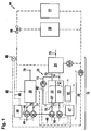
- a first embodiment of a combined heat and power plant 10 is shown.
- the combined heat and power plant 10 provides heat for two utilities, a space heating heating circuit 50, and a hot water system 51 for a building, not shown.
- the combined heat and power plant 10 has a fuel cell system 20 with an exemplary fuel cell 21, an anode 22 and a cathode 23 and an afterburner 24.
- Natural gas is supplied as a first fuel to the anode 22 in a flow path 70 through a first compressor 27.
- oxygen-containing air is supplied as an oxidizing agent to the cathode 23 in a flow path 71 through a second compressor 28.
- the first and second compressors 27, 28 are disposed in front of the fuel cell 21.
- the natural gas is reformed, inter alia, to hydrogen and carbon monoxide, and a first portion of the hydrogen and the carbon monoxide are electrochemically converted to produce an electric current and heat.
- a stream of unreacted hydrogen and carbon monoxide, water and carbon dioxide as the reaction product and other reformate products leaves the anode 22 on a flow path 72 and is partially directed in a recirculation flow path 73 to an inlet 22 'of the anode 22 and partially into the afterburner 24.
- a compression device 29 on the recirculation flow path 73 may adjust how much hydrogen returns to the anode 22 and how much hydrogen reaches the afterburner 24.
- the first proportion of hydrogen may vary between the optimum proportion and the lower limit value, ie approximately between 50 to 80%, depending on whether and to what extent the heat which is produced in accordance with the electric power demand Heat requirement covers.
- auxiliary heater 30 natural gas is burned as a second fuel.
- the natural gas is supplied to the auxiliary heater 30 on a flow path 76 and air by means of a fourth compressor 34 on a flow path 77 with the aid of a third compressor 33.
- Flow paths of the fuels and the air 70, 71, 72, 73, 74, 75, 76, 77, 78 are shown by solid lines.
- an inverter 41 which converts the direct current produced by the fuel cell 21 into alternating current, a constant current, a constant power or a constant voltage can be preset. Electrical leads to and from the inverter 41 are shown dotted. A connection to an electrical circuit with a consumer is not shown.
- Water as a heat receiving medium is circulated in a circuit 60.
- Flow paths of the circuit 60 are shown in dashed lines.
- the water flows through the afterburner 24 with the aid of a pump 61 and optionally with the aid of a pump 65, the auxiliary heater 30 arranged in parallel in terms of flow and absorbs heat, which is then released again in the use devices 50, 51.
- the use devices 50, 51 are fluidically arranged in parallel.
- the proportion of the water flowing through each of the use devices 50, 51 can be adjusted by a 3/2 way valve 66.
- the heat generated in the fuel cell 21 itself is transported by the streams of the flow paths 72, 74 in the afterburner 24 and transmitted from there to the water.
- the auxiliary heater 30 and the fuel cell system 20 have two separate control devices 47, 48. To both control devices 47, 48, a temperature of the water, which has left the afterburner 24 and optionally the auxiliary heater 30, transmitted. The temperature of the water is determined in a temperature measuring device 46, wherein the temperature measuring device 46 is arranged after a merger of the parallel flow paths through the auxiliary heater 30 and the afterburner 24 in the circuit 60.
- the control device 47 of the fuel cell system 20 sets the electric power of the first and second compressors 27, 28 and the compression device 29 on the basis of the determined temperature.
- the control device 47 also communicates with the inverter 41.
- the control device 48 of the auxiliary heater 30 sets the electric power of the third and fourth compressors 33, 34 on the basis of the determined temperature.
- control and / or regulation device 47 may also include a measurement of the requested electrical power of the building in the control and / or regulation, for example, with the aim of generating as little electrical power that can not be consumed in the same building.
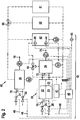
- Fig. 2 is a further embodiment of a combined heat and power plant 10 according to the invention with two use devices 50, 51 shown. The following is only on the differences compared to Fig. 1 received.
- the natural gas and the air are sucked in the auxiliary heater 30 by means of a compressor 35 arranged in a common exhaust stream 78, wherein the ratio of natural gas and air can be adjusted by a valve 31 in the flow path 76 and a valve 32 in the flow path 77.
- a compressor 27 'in the exhaust stream 75 the amount of natural gas and air and by valves 25, 26 in the flow paths 70, 71 set the ratio of natural gas to air. A recirculation does not take place.
- the afterburner 24 and the auxiliary heater 30 are fluidically arranged in the circuit 60 in series.
- a 3/2-way valve 64 behind the afterburner 24 may in times of high heat production of the fuel cell system 20 so be switched that the water does not transport the heat of the fuel cell system 20 to the use of devices 50, 51, but to a heat storage 42.
- the heat stored in this way can be made available to the use devices 50, 51 in times of high heat demand with the aid of the pump 63.
- the combined heat and power plant 10 has a common control device 40, which measures an outside temperature with the aid of a first temperature measuring device 43 and temperatures of the heat accumulator 42 at two different locations with the aid of a second and third temperature measuring device 44, 45.
- the measured temperatures are transmitted to communication means 46 to the control means 40, which then causes the valves 25, 26, 31, 32, the compressors 27 ', 35 and the inverter 41 are adjusted according to the inventive method.
- the control device 40 adjusts the pumps 61, 63, 65 (not shown).
- the controller 40 may also use a measurement of the requested electrical power of the building.
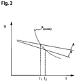
- Fig. 3 shows a plot of an electrical voltage U across an electric current I.
- the straight line A shows the dependence of the voltage U of the current I at a low first portion of the first fuel
- the straight line B shows the dependence of the voltage U of the current I at a represents a high first share of the first fuel.
- the curve P (const.) Shows a line of constant electric power P. At a low first part (straight line A), the current I is reduced with the same power P, so that aging of the fuel cell 21 is further reduced in addition to the effect of the reduced gas efficiency can.
Landscapes
- Engineering & Computer Science (AREA)
- Chemical & Material Sciences (AREA)
- General Engineering & Computer Science (AREA)
- Thermal Sciences (AREA)
- Combustion & Propulsion (AREA)
- Mechanical Engineering (AREA)
- Physics & Mathematics (AREA)
- Life Sciences & Earth Sciences (AREA)
- Manufacturing & Machinery (AREA)
- Sustainable Development (AREA)
- Sustainable Energy (AREA)
- Chemical Kinetics & Catalysis (AREA)
- Electrochemistry (AREA)
- General Chemical & Material Sciences (AREA)
- Fuel Cell (AREA)
Applications Claiming Priority (2)
| Application Number | Priority Date | Filing Date | Title |
|---|---|---|---|
| DE102010001011A DE102010001011A1 (de) | 2010-01-19 | 2010-01-19 | Verfahren zum Betrieb einer Kraft-Wärme-Kopplungsanlage |
| PCT/EP2011/050502 WO2011089082A2 (de) | 2010-01-19 | 2011-01-17 | Verfahren zum betrieb einer kraft-wärme-kopplungsanlage |
Publications (2)
| Publication Number | Publication Date |
|---|---|
| EP2526344A2 EP2526344A2 (de) | 2012-11-28 |
| EP2526344B1 true EP2526344B1 (de) | 2016-04-06 |
Family
ID=44307312
Family Applications (1)
| Application Number | Title | Priority Date | Filing Date |
|---|---|---|---|
| EP11700747.6A Not-in-force EP2526344B1 (de) | 2010-01-19 | 2011-01-17 | Verfahren zum betrieb einer kraft-wärme-kopplungsanlage |
Country Status (4)
| Country | Link |
|---|---|
| EP (1) | EP2526344B1 (enExample) |
| JP (1) | JP2013527555A (enExample) |
| DE (1) | DE102010001011A1 (enExample) |
| WO (1) | WO2011089082A2 (enExample) |
Families Citing this family (8)
| Publication number | Priority date | Publication date | Assignee | Title |
|---|---|---|---|---|
| DE102012221461A1 (de) | 2011-11-30 | 2013-06-06 | Robert Bosch Gmbh | Brennstoffzellensystem und Verfahren zum Betreiben eines Brennstoffzellensystems |
| DE102013204162A1 (de) | 2013-03-11 | 2014-09-11 | Robert Bosch Gmbh | Heizungsanlage sowie Verfahren zum Betreiben einer Heizungsanlage |
| DE102013207349A1 (de) | 2013-04-23 | 2014-10-23 | Robert Bosch Gmbh | Kraft-Wärme-Kopplungsanlage |
| DE102014204789A1 (de) | 2014-03-14 | 2015-09-17 | Volkswagen Aktiengesellschaft | Energiemanagementverfahren für ein Fahrzeug und Energiemanagementvorrichtung |
| DE102014226031A1 (de) | 2014-12-16 | 2016-06-16 | Volkswagen Aktiengesellschaft | Verfahren und Vorrichtung zum Prognostizieren einer Reichweite eines Fahrzeugs mit zumindest teilweise elektrischem Antrieb |
| AT521209B1 (de) * | 2018-05-03 | 2020-11-15 | Avl List Gmbh | Brennstoffzellensystem, stationäres Kraftwerk sowie Verfahren zum Betreiben eines Brennstoffzellensystems |
| CN114335630B (zh) * | 2021-12-30 | 2024-04-23 | 山东国创燃料电池技术创新中心有限公司 | 一种燃料电池热电联供控制方法及系统 |
| DE102023201614A1 (de) * | 2023-02-22 | 2024-08-22 | Robert Bosch Gesellschaft mit beschränkter Haftung | Brennstoffzellenvorrichtung und Brennstoffzellensystem |
Family Cites Families (19)
| Publication number | Priority date | Publication date | Assignee | Title |
|---|---|---|---|---|
| JPH07169474A (ja) * | 1993-12-15 | 1995-07-04 | Toshiba Corp | メタノール切替型燃料電池システム |
| ATE215745T1 (de) * | 1996-07-11 | 2002-04-15 | Sulzer Hexis Ag | Verfahren zur gleichzeitigen erzeugung von elektrischer energie und wärme für heizzwecke |
| JP2001185167A (ja) * | 1999-12-27 | 2001-07-06 | Daikin Ind Ltd | 燃料電池コジェネレーションシステム |
| JP2001185196A (ja) * | 1999-12-28 | 2001-07-06 | Daikin Ind Ltd | 燃料電池システム |
| JP3570355B2 (ja) * | 2000-08-01 | 2004-09-29 | 松下電器産業株式会社 | 燃料電池システム |
| AT410862B (de) | 2001-12-17 | 2003-08-25 | Vaillant Gmbh | Verfahren zum optimierten betrieb einer anlage zur gleichzeitigen erzeugung von elektrischer und thermischer energie mit einem brennstoffzellenheizgerät |
| AT411943B (de) * | 2002-05-06 | 2004-07-26 | Vaillant Gmbh | Verfahren zum betreiben einer brennstoffzellenanlage |
| JP2004150646A (ja) * | 2002-10-28 | 2004-05-27 | Sekisui Chem Co Ltd | コジェネレーションシステム |
| JP2004164868A (ja) * | 2002-11-08 | 2004-06-10 | Sanyo Electric Co Ltd | コージェネレーションシステムにおける貯湯方法及びその装置 |
| JP2004178962A (ja) * | 2002-11-27 | 2004-06-24 | Hitachi Ltd | 燃焼器を有する水素製造装置を用いた燃料電池発電システム |
| JP4831947B2 (ja) * | 2004-09-01 | 2011-12-07 | 東京瓦斯株式会社 | 燃料電池コジェネレーションシステム |
| AT503130B1 (de) * | 2006-03-15 | 2007-08-15 | Vaillant Austria Gmbh | Kombination eines heizgerätes mit einer brennstoffzellenanlage sowie ein verfahren zum betreiben dieser kombination |
| JP4944491B2 (ja) * | 2006-05-11 | 2012-05-30 | パナソニック株式会社 | 燃料電池システム |
| JP5191636B2 (ja) * | 2006-05-19 | 2013-05-08 | パナソニック株式会社 | コージェネレーションシステム |
| DE102007019359A1 (de) * | 2007-04-23 | 2008-10-30 | J. Eberspächer GmbH & Co. KG | Brennstoffzellensystem und zugehöriges Startverfahren |
| JP5185659B2 (ja) * | 2008-02-27 | 2013-04-17 | 三菱重工業株式会社 | コンバインドシステム |
| JP5164657B2 (ja) * | 2008-04-25 | 2013-03-21 | アイシン精機株式会社 | 燃料電池システム |
| JP2009289540A (ja) * | 2008-05-28 | 2009-12-10 | Nissan Motor Co Ltd | 燃料電池システム及びその運転方法 |
| DE102008037028B4 (de) * | 2008-08-08 | 2011-05-26 | Köhne, Stephan, Dr. | Brennstoffzellensystem für gasförmige Kohlenwassserstoffe und dazugehöriges Betriebsverfahren |
-
2010
- 2010-01-19 DE DE102010001011A patent/DE102010001011A1/de not_active Withdrawn
-
2011
- 2011-01-17 EP EP11700747.6A patent/EP2526344B1/de not_active Not-in-force
- 2011-01-17 WO PCT/EP2011/050502 patent/WO2011089082A2/de not_active Ceased
- 2011-01-17 JP JP2012549316A patent/JP2013527555A/ja active Pending
Also Published As
| Publication number | Publication date |
|---|---|
| EP2526344A2 (de) | 2012-11-28 |
| JP2013527555A (ja) | 2013-06-27 |
| WO2011089082A2 (de) | 2011-07-28 |
| DE102010001011A1 (de) | 2011-07-21 |
| WO2011089082A3 (de) | 2013-05-30 |
Similar Documents
| Publication | Publication Date | Title |
|---|---|---|
| EP2526344B1 (de) | Verfahren zum betrieb einer kraft-wärme-kopplungsanlage | |
| DE19857398B4 (de) | Brennstoffzellensystem, insbesondere für elektromotorisch angetriebene Fahrzeuge | |
| AT521209B1 (de) | Brennstoffzellensystem, stationäres Kraftwerk sowie Verfahren zum Betreiben eines Brennstoffzellensystems | |
| DE102007026003B4 (de) | Brennstoffzellensystem mit verbesserten Kaltstarteigenschaften sowie Verfahren | |
| EP2596154B1 (de) | Energiespeichervorrichtung und verfahren zum reversiblen speichern von energie | |
| DE102016203792B4 (de) | Brennstoffzellenmodul | |
| WO2023006724A2 (de) | Elektrolysezelle mit temperiervorrichtung, elektrolyseurstack aufweisend eine temperiervorrichtung, elektrolysesystem aufweisend den elektrolyseurstack und verfahren zur temperierung eines elektrolyseurstacks | |
| DE102017106900A1 (de) | Brennstoffzellensystem | |
| DE69933428T2 (de) | Kontrolvorrichtung für eine Reformierungsvorrichtung von Kraftstoff | |
| EP1906108A2 (de) | Wasserstoffheizung | |
| EP2989706A1 (de) | Kraft-wärme-kopplungsanlage und verfahren | |
| EP2971980A1 (de) | Heizungsanlage sowie verfahren zum betreiben einer heizungsanlage | |
| DE102011121691B4 (de) | Festoxidbrennstoffzellensystem und Verfahren zum Betreiben von Festoxidbrennstoffzellen | |
| DE112005001725B4 (de) | Brennstoffzellensystem | |
| DE10006006B4 (de) | Kraft-Wärme-Kopplungsapparat | |
| AT514511B1 (de) | Verfahren zur Regelung einer Brennstoffzelle | |
| EP2800190B1 (de) | Verfahren und Regelvorrichtung zum Betreiben einer Brennstoffzelle oder eines Brennstoffzellenstapels | |
| EP1726056B1 (de) | Brennstoffzellenanlage, verfahren zum starten und verfahren zum abschalten dieser anlage | |
| DE112015004029T5 (de) | Brennstoffzellensystem und steuerungsverfahren dafür | |
| DE102012221440A1 (de) | Brennstoffzellensystem | |
| EP1243046B1 (de) | Optimierung der betriebsparameter eines direkt-methanol-brennstoffzellensystems | |
| DE102017214726A1 (de) | Verfahren zur Bewertung eines Kühlmittelflusses eines Kühlmittelkreislaufs eines Brennstoffzellensystems, Brennstoffzellensystem und Fahrzeug | |
| DE19958830A1 (de) | Brennstoffzellensystem | |
| DE102011006531B4 (de) | Brennstoffzellensystem und zugehöriges Betriebsverfahren | |
| DE102022201050A1 (de) | Energieversorgungseinrichtung |
Legal Events
| Date | Code | Title | Description |
|---|---|---|---|
| PUAI | Public reference made under article 153(3) epc to a published international application that has entered the european phase |
Free format text: ORIGINAL CODE: 0009012 |
|
| AK | Designated contracting states |
Kind code of ref document: A2 Designated state(s): AL AT BE BG CH CY CZ DE DK EE ES FI FR GB GR HR HU IE IS IT LI LT LU LV MC MK MT NL NO PL PT RO RS SE SI SK SM TR |
|
| AX | Request for extension of the european patent |
Extension state: BA ME |
|
| DAX | Request for extension of the european patent (deleted) | ||
| R17D | Deferred search report published (corrected) |
Effective date: 20130530 |
|
| 17P | Request for examination filed |
Effective date: 20131202 |
|
| RBV | Designated contracting states (corrected) |
Designated state(s): AL AT BE BG CH CY CZ DE DK EE ES FI FR GB GR HR HU IE IS IT LI LT LU LV MC MK MT NL NO PL PT RO RS SE SI SK SM TR |
|
| REG | Reference to a national code |
Ref country code: DE Ref legal event code: R079 Ref document number: 502011009334 Country of ref document: DE Free format text: PREVIOUS MAIN CLASS: F24D0012020000 Ipc: F24D0011000000 |
|
| RIC1 | Information provided on ipc code assigned before grant |
Ipc: H01M 8/04 20060101ALI20150914BHEP Ipc: F24D 11/00 20060101AFI20150914BHEP Ipc: F24D 19/10 20060101ALI20150914BHEP Ipc: H01M 8/06 20060101ALI20150914BHEP |
|
| GRAP | Despatch of communication of intention to grant a patent |
Free format text: ORIGINAL CODE: EPIDOSNIGR1 |
|
| INTG | Intention to grant announced |
Effective date: 20151110 |
|
| GRAS | Grant fee paid |
Free format text: ORIGINAL CODE: EPIDOSNIGR3 |
|
| GRAA | (expected) grant |
Free format text: ORIGINAL CODE: 0009210 |
|
| AK | Designated contracting states |
Kind code of ref document: B1 Designated state(s): AL AT BE BG CH CY CZ DE DK EE ES FI FR GB GR HR HU IE IS IT LI LT LU LV MC MK MT NL NO PL PT RO RS SE SI SK SM TR |
|
| REG | Reference to a national code |
Ref country code: GB Ref legal event code: FG4D Free format text: NOT ENGLISH |
|
| REG | Reference to a national code |
Ref country code: AT Ref legal event code: REF Ref document number: 788254 Country of ref document: AT Kind code of ref document: T Effective date: 20160415 Ref country code: CH Ref legal event code: EP |
|
| REG | Reference to a national code |
Ref country code: IE Ref legal event code: FG4D Free format text: LANGUAGE OF EP DOCUMENT: GERMAN |
|
| REG | Reference to a national code |
Ref country code: DE Ref legal event code: R096 Ref document number: 502011009334 Country of ref document: DE |
|
| REG | Reference to a national code |
Ref country code: LT Ref legal event code: MG4D Ref country code: NL Ref legal event code: MP Effective date: 20160406 |
|
| PG25 | Lapsed in a contracting state [announced via postgrant information from national office to epo] |
Ref country code: NL Free format text: LAPSE BECAUSE OF FAILURE TO SUBMIT A TRANSLATION OF THE DESCRIPTION OR TO PAY THE FEE WITHIN THE PRESCRIBED TIME-LIMIT Effective date: 20160406 |
|
| PG25 | Lapsed in a contracting state [announced via postgrant information from national office to epo] |
Ref country code: PL Free format text: LAPSE BECAUSE OF FAILURE TO SUBMIT A TRANSLATION OF THE DESCRIPTION OR TO PAY THE FEE WITHIN THE PRESCRIBED TIME-LIMIT Effective date: 20160406 Ref country code: IS Free format text: LAPSE BECAUSE OF FAILURE TO SUBMIT A TRANSLATION OF THE DESCRIPTION OR TO PAY THE FEE WITHIN THE PRESCRIBED TIME-LIMIT Effective date: 20160806 Ref country code: FI Free format text: LAPSE BECAUSE OF FAILURE TO SUBMIT A TRANSLATION OF THE DESCRIPTION OR TO PAY THE FEE WITHIN THE PRESCRIBED TIME-LIMIT Effective date: 20160406 Ref country code: LT Free format text: LAPSE BECAUSE OF FAILURE TO SUBMIT A TRANSLATION OF THE DESCRIPTION OR TO PAY THE FEE WITHIN THE PRESCRIBED TIME-LIMIT Effective date: 20160406 Ref country code: NO Free format text: LAPSE BECAUSE OF FAILURE TO SUBMIT A TRANSLATION OF THE DESCRIPTION OR TO PAY THE FEE WITHIN THE PRESCRIBED TIME-LIMIT Effective date: 20160706 |
|
| PG25 | Lapsed in a contracting state [announced via postgrant information from national office to epo] |
Ref country code: GR Free format text: LAPSE BECAUSE OF FAILURE TO SUBMIT A TRANSLATION OF THE DESCRIPTION OR TO PAY THE FEE WITHIN THE PRESCRIBED TIME-LIMIT Effective date: 20160707 Ref country code: SE Free format text: LAPSE BECAUSE OF FAILURE TO SUBMIT A TRANSLATION OF THE DESCRIPTION OR TO PAY THE FEE WITHIN THE PRESCRIBED TIME-LIMIT Effective date: 20160406 Ref country code: HR Free format text: LAPSE BECAUSE OF FAILURE TO SUBMIT A TRANSLATION OF THE DESCRIPTION OR TO PAY THE FEE WITHIN THE PRESCRIBED TIME-LIMIT Effective date: 20160406 Ref country code: RS Free format text: LAPSE BECAUSE OF FAILURE TO SUBMIT A TRANSLATION OF THE DESCRIPTION OR TO PAY THE FEE WITHIN THE PRESCRIBED TIME-LIMIT Effective date: 20160406 Ref country code: PT Free format text: LAPSE BECAUSE OF FAILURE TO SUBMIT A TRANSLATION OF THE DESCRIPTION OR TO PAY THE FEE WITHIN THE PRESCRIBED TIME-LIMIT Effective date: 20160808 Ref country code: LV Free format text: LAPSE BECAUSE OF FAILURE TO SUBMIT A TRANSLATION OF THE DESCRIPTION OR TO PAY THE FEE WITHIN THE PRESCRIBED TIME-LIMIT Effective date: 20160406 Ref country code: ES Free format text: LAPSE BECAUSE OF FAILURE TO SUBMIT A TRANSLATION OF THE DESCRIPTION OR TO PAY THE FEE WITHIN THE PRESCRIBED TIME-LIMIT Effective date: 20160406 |
|
| PG25 | Lapsed in a contracting state [announced via postgrant information from national office to epo] |
Ref country code: IT Free format text: LAPSE BECAUSE OF FAILURE TO SUBMIT A TRANSLATION OF THE DESCRIPTION OR TO PAY THE FEE WITHIN THE PRESCRIBED TIME-LIMIT Effective date: 20160406 |
|
| REG | Reference to a national code |
Ref country code: DE Ref legal event code: R097 Ref document number: 502011009334 Country of ref document: DE |
|
| REG | Reference to a national code |
Ref country code: FR Ref legal event code: PLFP Year of fee payment: 7 |
|
| PG25 | Lapsed in a contracting state [announced via postgrant information from national office to epo] |
Ref country code: SK Free format text: LAPSE BECAUSE OF FAILURE TO SUBMIT A TRANSLATION OF THE DESCRIPTION OR TO PAY THE FEE WITHIN THE PRESCRIBED TIME-LIMIT Effective date: 20160406 Ref country code: RO Free format text: LAPSE BECAUSE OF FAILURE TO SUBMIT A TRANSLATION OF THE DESCRIPTION OR TO PAY THE FEE WITHIN THE PRESCRIBED TIME-LIMIT Effective date: 20160406 Ref country code: CZ Free format text: LAPSE BECAUSE OF FAILURE TO SUBMIT A TRANSLATION OF THE DESCRIPTION OR TO PAY THE FEE WITHIN THE PRESCRIBED TIME-LIMIT Effective date: 20160406 Ref country code: DK Free format text: LAPSE BECAUSE OF FAILURE TO SUBMIT A TRANSLATION OF THE DESCRIPTION OR TO PAY THE FEE WITHIN THE PRESCRIBED TIME-LIMIT Effective date: 20160406 Ref country code: EE Free format text: LAPSE BECAUSE OF FAILURE TO SUBMIT A TRANSLATION OF THE DESCRIPTION OR TO PAY THE FEE WITHIN THE PRESCRIBED TIME-LIMIT Effective date: 20160406 |
|
| PLBE | No opposition filed within time limit |
Free format text: ORIGINAL CODE: 0009261 |
|
| STAA | Information on the status of an ep patent application or granted ep patent |
Free format text: STATUS: NO OPPOSITION FILED WITHIN TIME LIMIT |
|
| PG25 | Lapsed in a contracting state [announced via postgrant information from national office to epo] |
Ref country code: SM Free format text: LAPSE BECAUSE OF FAILURE TO SUBMIT A TRANSLATION OF THE DESCRIPTION OR TO PAY THE FEE WITHIN THE PRESCRIBED TIME-LIMIT Effective date: 20160406 |
|
| 26N | No opposition filed |
Effective date: 20170110 |
|
| PG25 | Lapsed in a contracting state [announced via postgrant information from national office to epo] |
Ref country code: BE Free format text: LAPSE BECAUSE OF NON-PAYMENT OF DUE FEES Effective date: 20170131 Ref country code: SI Free format text: LAPSE BECAUSE OF FAILURE TO SUBMIT A TRANSLATION OF THE DESCRIPTION OR TO PAY THE FEE WITHIN THE PRESCRIBED TIME-LIMIT Effective date: 20160406 |
|
| REG | Reference to a national code |
Ref country code: CH Ref legal event code: PL |
|
| PG25 | Lapsed in a contracting state [announced via postgrant information from national office to epo] |
Ref country code: MC Free format text: LAPSE BECAUSE OF FAILURE TO SUBMIT A TRANSLATION OF THE DESCRIPTION OR TO PAY THE FEE WITHIN THE PRESCRIBED TIME-LIMIT Effective date: 20160406 |
|
| PG25 | Lapsed in a contracting state [announced via postgrant information from national office to epo] |
Ref country code: LI Free format text: LAPSE BECAUSE OF NON-PAYMENT OF DUE FEES Effective date: 20170131 Ref country code: CH Free format text: LAPSE BECAUSE OF NON-PAYMENT OF DUE FEES Effective date: 20170131 |
|
| REG | Reference to a national code |
Ref country code: IE Ref legal event code: MM4A |
|
| PG25 | Lapsed in a contracting state [announced via postgrant information from national office to epo] |
Ref country code: LU Free format text: LAPSE BECAUSE OF NON-PAYMENT OF DUE FEES Effective date: 20170117 |
|
| REG | Reference to a national code |
Ref country code: FR Ref legal event code: PLFP Year of fee payment: 8 |
|
| REG | Reference to a national code |
Ref country code: BE Ref legal event code: MM Effective date: 20170131 |
|
| PG25 | Lapsed in a contracting state [announced via postgrant information from national office to epo] |
Ref country code: IE Free format text: LAPSE BECAUSE OF NON-PAYMENT OF DUE FEES Effective date: 20170117 |
|
| REG | Reference to a national code |
Ref country code: AT Ref legal event code: MM01 Ref document number: 788254 Country of ref document: AT Kind code of ref document: T Effective date: 20170117 |
|
| PG25 | Lapsed in a contracting state [announced via postgrant information from national office to epo] |
Ref country code: AT Free format text: LAPSE BECAUSE OF NON-PAYMENT OF DUE FEES Effective date: 20170117 |
|
| PG25 | Lapsed in a contracting state [announced via postgrant information from national office to epo] |
Ref country code: MT Free format text: LAPSE BECAUSE OF FAILURE TO SUBMIT A TRANSLATION OF THE DESCRIPTION OR TO PAY THE FEE WITHIN THE PRESCRIBED TIME-LIMIT Effective date: 20160406 |
|
| PG25 | Lapsed in a contracting state [announced via postgrant information from national office to epo] |
Ref country code: AL Free format text: LAPSE BECAUSE OF FAILURE TO SUBMIT A TRANSLATION OF THE DESCRIPTION OR TO PAY THE FEE WITHIN THE PRESCRIBED TIME-LIMIT Effective date: 20160406 |
|
| PG25 | Lapsed in a contracting state [announced via postgrant information from national office to epo] |
Ref country code: HU Free format text: LAPSE BECAUSE OF FAILURE TO SUBMIT A TRANSLATION OF THE DESCRIPTION OR TO PAY THE FEE WITHIN THE PRESCRIBED TIME-LIMIT; INVALID AB INITIO Effective date: 20110117 |
|
| PG25 | Lapsed in a contracting state [announced via postgrant information from national office to epo] |
Ref country code: BG Free format text: LAPSE BECAUSE OF FAILURE TO SUBMIT A TRANSLATION OF THE DESCRIPTION OR TO PAY THE FEE WITHIN THE PRESCRIBED TIME-LIMIT Effective date: 20160406 |
|
| PG25 | Lapsed in a contracting state [announced via postgrant information from national office to epo] |
Ref country code: CY Free format text: LAPSE BECAUSE OF NON-PAYMENT OF DUE FEES Effective date: 20160406 |
|
| PG25 | Lapsed in a contracting state [announced via postgrant information from national office to epo] |
Ref country code: MK Free format text: LAPSE BECAUSE OF FAILURE TO SUBMIT A TRANSLATION OF THE DESCRIPTION OR TO PAY THE FEE WITHIN THE PRESCRIBED TIME-LIMIT Effective date: 20160406 |
|
| PG25 | Lapsed in a contracting state [announced via postgrant information from national office to epo] |
Ref country code: TR Free format text: LAPSE BECAUSE OF FAILURE TO SUBMIT A TRANSLATION OF THE DESCRIPTION OR TO PAY THE FEE WITHIN THE PRESCRIBED TIME-LIMIT Effective date: 20160406 |
|
| PGFP | Annual fee paid to national office [announced via postgrant information from national office to epo] |
Ref country code: DE Payment date: 20240322 Year of fee payment: 14 Ref country code: GB Payment date: 20240117 Year of fee payment: 14 |
|
| PGFP | Annual fee paid to national office [announced via postgrant information from national office to epo] |
Ref country code: FR Payment date: 20240124 Year of fee payment: 14 |
|
| REG | Reference to a national code |
Ref country code: DE Ref legal event code: R119 Ref document number: 502011009334 Country of ref document: DE |
|
| GBPC | Gb: european patent ceased through non-payment of renewal fee |
Effective date: 20250117 |
|
| PG25 | Lapsed in a contracting state [announced via postgrant information from national office to epo] |
Ref country code: DE Free format text: LAPSE BECAUSE OF NON-PAYMENT OF DUE FEES Effective date: 20250801 |
|
| PG25 | Lapsed in a contracting state [announced via postgrant information from national office to epo] |
Ref country code: GB Free format text: LAPSE BECAUSE OF NON-PAYMENT OF DUE FEES Effective date: 20250117 |
|
| PG25 | Lapsed in a contracting state [announced via postgrant information from national office to epo] |
Ref country code: FR Free format text: LAPSE BECAUSE OF NON-PAYMENT OF DUE FEES Effective date: 20250131 |