EP2800190B1 - Verfahren und Regelvorrichtung zum Betreiben einer Brennstoffzelle oder eines Brennstoffzellenstapels - Google Patents
Verfahren und Regelvorrichtung zum Betreiben einer Brennstoffzelle oder eines Brennstoffzellenstapels Download PDFInfo
- Publication number
- EP2800190B1 EP2800190B1 EP14164660.4A EP14164660A EP2800190B1 EP 2800190 B1 EP2800190 B1 EP 2800190B1 EP 14164660 A EP14164660 A EP 14164660A EP 2800190 B1 EP2800190 B1 EP 2800190B1
- Authority
- EP
- European Patent Office
- Prior art keywords
- fuel cell
- cell stack
- operating temperature
- gas flow
- value
- Prior art date
- Legal status (The legal status is an assumption and is not a legal conclusion. Google has not performed a legal analysis and makes no representation as to the accuracy of the status listed.)
- Not-in-force
Links
- 239000000446 fuel Substances 0.000 title claims description 233
- 238000000034 method Methods 0.000 title claims description 41
- 239000002737 fuel gas Substances 0.000 claims description 51
- 230000032683 aging Effects 0.000 claims description 43
- 230000007423 decrease Effects 0.000 claims description 26
- 239000007789 gas Substances 0.000 claims description 21
- 230000000750 progressive effect Effects 0.000 claims description 8
- 230000001419 dependent effect Effects 0.000 claims description 5
- 230000001105 regulatory effect Effects 0.000 claims description 5
- 230000003247 decreasing effect Effects 0.000 claims 1
- VNWKTOKETHGBQD-UHFFFAOYSA-N methane Chemical compound C VNWKTOKETHGBQD-UHFFFAOYSA-N 0.000 description 10
- 238000005297 material degradation process Methods 0.000 description 5
- 239000012080 ambient air Substances 0.000 description 3
- 230000001934 delay Effects 0.000 description 3
- 230000000694 effects Effects 0.000 description 3
- UGFAIRIUMAVXCW-UHFFFAOYSA-N Carbon monoxide Chemical compound [O+]#[C-] UGFAIRIUMAVXCW-UHFFFAOYSA-N 0.000 description 2
- UFHFLCQGNIYNRP-UHFFFAOYSA-N Hydrogen Chemical compound [H][H] UFHFLCQGNIYNRP-UHFFFAOYSA-N 0.000 description 2
- 239000003570 air Substances 0.000 description 2
- 229910002091 carbon monoxide Inorganic materials 0.000 description 2
- 238000006243 chemical reaction Methods 0.000 description 2
- 230000005611 electricity Effects 0.000 description 2
- 239000001257 hydrogen Substances 0.000 description 2
- 229910052739 hydrogen Inorganic materials 0.000 description 2
- 239000003345 natural gas Substances 0.000 description 2
- 230000001590 oxidative effect Effects 0.000 description 2
- 239000007787 solid Substances 0.000 description 2
- XLYOFNOQVPJJNP-UHFFFAOYSA-N water Substances O XLYOFNOQVPJJNP-UHFFFAOYSA-N 0.000 description 2
- 230000006978 adaptation Effects 0.000 description 1
- QVGXLLKOCUKJST-UHFFFAOYSA-N atomic oxygen Chemical compound [O] QVGXLLKOCUKJST-UHFFFAOYSA-N 0.000 description 1
- 230000033228 biological regulation Effects 0.000 description 1
- 230000001427 coherent effect Effects 0.000 description 1
- 230000001276 controlling effect Effects 0.000 description 1
- 238000009795 derivation Methods 0.000 description 1
- 238000010438 heat treatment Methods 0.000 description 1
- 239000000203 mixture Substances 0.000 description 1
- 239000001301 oxygen Substances 0.000 description 1
- 229910052760 oxygen Inorganic materials 0.000 description 1
- 239000000376 reactant Substances 0.000 description 1
- 239000007858 starting material Substances 0.000 description 1
- 230000036962 time dependent Effects 0.000 description 1
Images

Classifications
-
- H—ELECTRICITY
- H01—ELECTRIC ELEMENTS
- H01M—PROCESSES OR MEANS, e.g. BATTERIES, FOR THE DIRECT CONVERSION OF CHEMICAL ENERGY INTO ELECTRICAL ENERGY
- H01M8/00—Fuel cells; Manufacture thereof
- H01M8/04—Auxiliary arrangements, e.g. for control of pressure or for circulation of fluids
- H01M8/04298—Processes for controlling fuel cells or fuel cell systems
- H01M8/04694—Processes for controlling fuel cells or fuel cell systems characterised by variables to be controlled
- H01M8/04701—Temperature
-
- H—ELECTRICITY
- H01—ELECTRIC ELEMENTS
- H01M—PROCESSES OR MEANS, e.g. BATTERIES, FOR THE DIRECT CONVERSION OF CHEMICAL ENERGY INTO ELECTRICAL ENERGY
- H01M8/00—Fuel cells; Manufacture thereof
- H01M8/04—Auxiliary arrangements, e.g. for control of pressure or for circulation of fluids
- H01M8/04007—Auxiliary arrangements, e.g. for control of pressure or for circulation of fluids related to heat exchange
-
- H—ELECTRICITY
- H01—ELECTRIC ELEMENTS
- H01M—PROCESSES OR MEANS, e.g. BATTERIES, FOR THE DIRECT CONVERSION OF CHEMICAL ENERGY INTO ELECTRICAL ENERGY
- H01M8/00—Fuel cells; Manufacture thereof
- H01M8/04—Auxiliary arrangements, e.g. for control of pressure or for circulation of fluids
- H01M8/04298—Processes for controlling fuel cells or fuel cell systems
- H01M8/04313—Processes for controlling fuel cells or fuel cell systems characterised by the detection or assessment of variables; characterised by the detection or assessment of failure or abnormal function
- H01M8/0432—Temperature; Ambient temperature
-
- H—ELECTRICITY
- H01—ELECTRIC ELEMENTS
- H01M—PROCESSES OR MEANS, e.g. BATTERIES, FOR THE DIRECT CONVERSION OF CHEMICAL ENERGY INTO ELECTRICAL ENERGY
- H01M8/00—Fuel cells; Manufacture thereof
- H01M8/04—Auxiliary arrangements, e.g. for control of pressure or for circulation of fluids
- H01M8/04298—Processes for controlling fuel cells or fuel cell systems
- H01M8/04313—Processes for controlling fuel cells or fuel cell systems characterised by the detection or assessment of variables; characterised by the detection or assessment of failure or abnormal function
- H01M8/0438—Pressure; Ambient pressure; Flow
-
- H—ELECTRICITY
- H01—ELECTRIC ELEMENTS
- H01M—PROCESSES OR MEANS, e.g. BATTERIES, FOR THE DIRECT CONVERSION OF CHEMICAL ENERGY INTO ELECTRICAL ENERGY
- H01M8/00—Fuel cells; Manufacture thereof
- H01M8/04—Auxiliary arrangements, e.g. for control of pressure or for circulation of fluids
- H01M8/04298—Processes for controlling fuel cells or fuel cell systems
- H01M8/04313—Processes for controlling fuel cells or fuel cell systems characterised by the detection or assessment of variables; characterised by the detection or assessment of failure or abnormal function
- H01M8/04537—Electric variables
- H01M8/04544—Voltage
- H01M8/04559—Voltage of fuel cell stacks
-
- H—ELECTRICITY
- H01—ELECTRIC ELEMENTS
- H01M—PROCESSES OR MEANS, e.g. BATTERIES, FOR THE DIRECT CONVERSION OF CHEMICAL ENERGY INTO ELECTRICAL ENERGY
- H01M8/00—Fuel cells; Manufacture thereof
- H01M8/04—Auxiliary arrangements, e.g. for control of pressure or for circulation of fluids
- H01M8/04298—Processes for controlling fuel cells or fuel cell systems
- H01M8/04313—Processes for controlling fuel cells or fuel cell systems characterised by the detection or assessment of variables; characterised by the detection or assessment of failure or abnormal function
- H01M8/04537—Electric variables
- H01M8/04604—Power, energy, capacity or load
-
- H—ELECTRICITY
- H01—ELECTRIC ELEMENTS
- H01M—PROCESSES OR MEANS, e.g. BATTERIES, FOR THE DIRECT CONVERSION OF CHEMICAL ENERGY INTO ELECTRICAL ENERGY
- H01M8/00—Fuel cells; Manufacture thereof
- H01M8/04—Auxiliary arrangements, e.g. for control of pressure or for circulation of fluids
- H01M8/04298—Processes for controlling fuel cells or fuel cell systems
- H01M8/04313—Processes for controlling fuel cells or fuel cell systems characterised by the detection or assessment of variables; characterised by the detection or assessment of failure or abnormal function
- H01M8/04537—Electric variables
- H01M8/04634—Other electric variables, e.g. resistance or impedance
- H01M8/04641—Other electric variables, e.g. resistance or impedance of the individual fuel cell
-
- H—ELECTRICITY
- H01—ELECTRIC ELEMENTS
- H01M—PROCESSES OR MEANS, e.g. BATTERIES, FOR THE DIRECT CONVERSION OF CHEMICAL ENERGY INTO ELECTRICAL ENERGY
- H01M8/00—Fuel cells; Manufacture thereof
- H01M8/04—Auxiliary arrangements, e.g. for control of pressure or for circulation of fluids
- H01M8/04298—Processes for controlling fuel cells or fuel cell systems
- H01M8/04694—Processes for controlling fuel cells or fuel cell systems characterised by variables to be controlled
- H01M8/04701—Temperature
- H01M8/04731—Temperature of other components of a fuel cell or fuel cell stacks
-
- H—ELECTRICITY
- H01—ELECTRIC ELEMENTS
- H01M—PROCESSES OR MEANS, e.g. BATTERIES, FOR THE DIRECT CONVERSION OF CHEMICAL ENERGY INTO ELECTRICAL ENERGY
- H01M8/00—Fuel cells; Manufacture thereof
- H01M8/04—Auxiliary arrangements, e.g. for control of pressure or for circulation of fluids
- H01M8/04298—Processes for controlling fuel cells or fuel cell systems
- H01M8/04694—Processes for controlling fuel cells or fuel cell systems characterised by variables to be controlled
- H01M8/04746—Pressure; Flow
- H01M8/04753—Pressure; Flow of fuel cell reactants
-
- H—ELECTRICITY
- H01—ELECTRIC ELEMENTS
- H01M—PROCESSES OR MEANS, e.g. BATTERIES, FOR THE DIRECT CONVERSION OF CHEMICAL ENERGY INTO ELECTRICAL ENERGY
- H01M8/00—Fuel cells; Manufacture thereof
- H01M8/04—Auxiliary arrangements, e.g. for control of pressure or for circulation of fluids
- H01M8/04298—Processes for controlling fuel cells or fuel cell systems
- H01M8/04694—Processes for controlling fuel cells or fuel cell systems characterised by variables to be controlled
- H01M8/04858—Electric variables
- H01M8/04865—Voltage
-
- H—ELECTRICITY
- H01—ELECTRIC ELEMENTS
- H01M—PROCESSES OR MEANS, e.g. BATTERIES, FOR THE DIRECT CONVERSION OF CHEMICAL ENERGY INTO ELECTRICAL ENERGY
- H01M8/00—Fuel cells; Manufacture thereof
- H01M8/10—Fuel cells with solid electrolytes
- H01M8/12—Fuel cells with solid electrolytes operating at high temperature, e.g. with stabilised ZrO2 electrolyte
- H01M2008/1293—Fuel cells with solid oxide electrolytes
-
- H—ELECTRICITY
- H01—ELECTRIC ELEMENTS
- H01M—PROCESSES OR MEANS, e.g. BATTERIES, FOR THE DIRECT CONVERSION OF CHEMICAL ENERGY INTO ELECTRICAL ENERGY
- H01M8/00—Fuel cells; Manufacture thereof
- H01M8/04—Auxiliary arrangements, e.g. for control of pressure or for circulation of fluids
- H01M8/04082—Arrangements for control of reactant parameters, e.g. pressure or concentration
-
- Y—GENERAL TAGGING OF NEW TECHNOLOGICAL DEVELOPMENTS; GENERAL TAGGING OF CROSS-SECTIONAL TECHNOLOGIES SPANNING OVER SEVERAL SECTIONS OF THE IPC; TECHNICAL SUBJECTS COVERED BY FORMER USPC CROSS-REFERENCE ART COLLECTIONS [XRACs] AND DIGESTS
- Y02—TECHNOLOGIES OR APPLICATIONS FOR MITIGATION OR ADAPTATION AGAINST CLIMATE CHANGE
- Y02E—REDUCTION OF GREENHOUSE GAS [GHG] EMISSIONS, RELATED TO ENERGY GENERATION, TRANSMISSION OR DISTRIBUTION
- Y02E60/00—Enabling technologies; Technologies with a potential or indirect contribution to GHG emissions mitigation
- Y02E60/30—Hydrogen technology
- Y02E60/50—Fuel cells
Definitions
- the invention relates to a method for operating a fuel cell or a fuel cell stack according to the preamble of claim 1.
- Fuel cells particularly solid oxide fuel cell (SOFC) high temperature fuel cells, allow the energy of a fuel to be utilized through energy conversion.
- SOFC solid oxide fuel cell
- both electrical energy that is generated due to electrochemical processes, as well as thermal energy, which is obtained in the form of hot exhaust gases of the processes can be used.
- Gaseous streams of two educts are passed through the cells separately.
- the first educt which is in particular ambient air, contains oxidizing components, the second educt reducing components.
- a methane-containing gas for example natural gas
- a reformer before it enters the cells where it is introduced, for example by means of an additional feed of water and possibly air and under the supply of process heat into the reducing Components hydrogen and carbon monoxide is converted.
- process heat required in the reformer can be used with advantage the hot exhaust gas.
- a method for operating a fuel cell battery is, for example, document EP1 205 993 A1 known. In this procedure, one of the Power requirement dependent control of the fuel cell battery described.
- fuel cells and fuel cell stacks are usually operated at a constant operating temperature and, as long as the power requirement and the gas composition does not change, with a constant fuel gas flow.
- the operation is usually carried out in the vicinity of the achievable for a given fuel gas flow maximum electrical power, since there the fuel gas utilization is best.
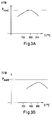
- Fig. 3A shows a typical course of the output electric power P as a function of the operating temperature T for a fuel cell or a fuel cell stack when new for a given fuel gas flow.
- the maximum P max0 of the electrical power output is clearly visible.
- Fig. 3B shows a typical course of the output electric power P as a function of the operating temperature T for a fuel cell or a fuel cell stack after 20,000 hours of operation at an operating temperature of 750 ° C and held constant fuel gas flow.
- the maximum of the electrical power output has dropped from the maximum P max0 in the new state of the fuel cell or the fuel cell stack and has in comparison with the in Fig. 3A shown performance of the power shifted to higher operating temperatures.
- the material degradation also depends on the operating temperature. At lower temperatures, the material degradation is lower, but the internal resistance is higher due to the lower temperature, so that the material degradation makes more noticeable.
- the object of the invention is to provide a method for operating a fuel cell or a fuel cell stack, with which extends the life of the fuel cell or the fuel cell stack and the Effects of aging on the delivered electrical power can be reduced.
- the method according to the invention for operating a fuel cell or a fuel cell stack which, given a fuel gas flow, has an electrical maximum power that can be delivered as a function of the operating temperature and an aging dependent on the operating time, which causes the electrical internal resistance to increase as the operating time progresses , characterized in that for a new fuel cell or for a new fuel cell stack an initial value of the operating temperature is set, which is conveniently smaller than the maximum for the fuel cell or the fuel cell stack specified operating temperature, and the fuel cell or the fuel cell stack is controlled so that the decrease in the electrical power delivered as a result of aging is partially or completely compensated by the operating temperature of the fuel cell or the fuel cell stack with progress aging is increased.
- the operating temperature is increased as the aging proceeds until the maximum specified for the fuel cell or the fuel cell stack operating temperature is reached.
- the initial value of the operating temperature is advantageously less than or equal to the operating temperature at which the maximum electrical power is reached.
- the initial operating temperature is typically between 740 ° C and 800 ° C.
- an upper limit is specified for the electrical power output, which upper limit may be, for example, at most 80% or at most 90% or at most 95% of the maximum electric power of a new fuel cell or a new fuel cell stack.
- the decrease in the electrical power output due to aging is compensated for by lowering the electrical output voltage of the fuel cell or fuel cell stack as the aging progresses, for example, giving an initial value for the output voltage that is higher than the output voltage value. in which for a given fuel gas flow and given operating temperature, the electrical output power is maximum.
- the output voltage is lowered until the output voltage value is reached at which the electrical output power becomes maximum for a given fuel gas flow and given operating temperature.
- the decrease in the electrical power output as a result of aging is compensated for by increasing the fuel gas flow as the aging progresses, whereby, for example, an initial value for the fuel gas flow which is smaller than the maximum for the fuel cell or the fuel cell stack can be specified specified fuel gas flow.
- the fuel gas flow is increased until the maximum specified for the fuel cell or the fuel cell stack fuel gas flow is reached.
- the embodiments described above may be combined in a different order of twos or threes by, for example, setting an initial value for the electrical output voltage which is higher than the output voltage value at which the electrical output power becomes maximum for a given fuel gas flow and given operating temperature, and / or specifying an initial value for the fuel gas flow that is less than the maximum fuel gas flow specified for the fuel cell or the fuel cell stack and an initial value of the operating temperature that is less than the maximum operating temperature specified for the fuel cell or the fuel cell stack, occasionally, in a first phase, compensating for the decrease in electrical power delivered as a result of aging by lowering the electrical output voltage until the output voltage value is reached at which the electrical output power becomes maximum for a given fuel gas flow and given operating temperature, occasionally in a second phase compensating for the decrease in electrical power output due to aging by increasing the fuel gas flow until the maximum fuel gas flow specified for the fuel cell or stack is reached, and wherein occasionally, in a third phase, the decrease in electrical power output due to aging is compensated for by increasing the operating temperature of the fuel cell
- a current-voltage characteristic of the fuel cell or the fuel cell stack whose slope has a minimum, and detected in each case from the detected current-voltage characteristic curve a value for the minimum of the slope or one with the minimum determines the gradient coherent value R min , wherein by a mathematical combination of the determined value with a predetermined offset value R offset , in particular by adding a predetermined offset value to the determined value, a guide value for the operating point determined and the output voltage of the fuel cell or the fuel cell stack using the regulated in this way.
- the output voltage of the fuel cell or the fuel cell stack is controlled via a controllable load or a controllable current sink, which are connected to the output of the fuel cell or the fuel cell stack.
- control device for a fuel cell, a fuel cell stack or a fuel cell system which is adapted to the fuel cell or the fuel cell stack is described or to control and / or regulate the fuel cell system by means of a method according to one of the embodiments and variants described above.
- control device additionally includes a controllable load or a controllable current sink, which are connectable to the output of the fuel cell or the fuel cell stack to regulate the output voltage of the fuel cell or the fuel cell stack via the controllable load or the controllable current sink, wherein the controllable Consumers may be, for example, a voltage converter or an inverter whose outputs can be connected to a power grid to feed the electricity generated in the fuel cell into the power grid.
- the method for operating a fuel cell or a fuel cell stack and the control device as well as the fuel cell and the fuel cell stack according to the present invention have the advantage that, thanks to the lower initial operating temperature, aging can be reduced and the service life of the fuel cell and the fuel cell stack extended, and the user at the same time thanks to the regulation, which partially or completely compensates for the decrease in the electrical power delivered as a result of aging, a substantially constant electric power is available over a large part of the service life.
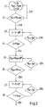
- Fig. 1 shows an embodiment of a fuel cell stack 1 with a control device 8 according to the present invention.
- An arrangement of a fuel cell stack with a control device is also referred to below as a fuel cell system 10.
- the fuel cell stack 1 may be constructed of SOFC (Solid Oxide Fuel Cell) type high temperature fuel cells that are typically operated at a temperature of 600 ° C to 1000 ° C, and allows the use of energy of a fuel by energy conversion , In this case, both electrical energy that is generated due to electrochemical processes, as well as thermal energy, which is obtained in the form of hot exhaust gases of the processes can be used.
- gaseous streams of two educts A, B are passed through the cells separately.
- the first educt A which may be, for example, ambient air, contains oxidizing components, the second educt B reducing components.
- the second reactant B used is a methane-containing gas (for example natural gas) which, before entering the cells, is replaced by a gas containing methane Fig. 1 not shown reformer and there, for example, by means of an additional feed of water W and optionally air and under supply of process heat in the reducing components Hydrogen and carbon monoxide is converted.
- a source for the process heat required in the reformer can be used with advantage the hot exhaust gas.
- the fuel cell stack 1 is usually connected to a heat exchanger 2, in which the hot exhaust gases from the fuel cell stack heat can be withdrawn.
- the heat exchanger 2 is advantageously connected to a heating circuit 2 '.
- the exhaust gases C can then be released into the open or the residual oxygen in the exhaust gases can in an additional burner, the in Fig. 1 not shown, can be used.
- the fuel cell or the fuel cell stack 1 or the fuel cell system according to the present invention contain a control device 8 which is set up to control and / or regulate the fuel cell or the fuel cell stack or the fuel cell system according to a method of the present invention described below.
- the method according to the present invention for operating a fuel cell or a fuel cell stack 1, which for a given fuel gas flow has an electrical maximum power that can be delivered depending on the operating temperature, as well as a function of the operating time dependent aging, which causes, as the operating time of the electrical internal resistance increases and, as a rule, the electrical power output decreases, is characterized in that for a new fuel cell or for a new fuel cell stack an initial value of the operating temperature is set, which is conveniently smaller than the maximum for the fuel cell or the fuel cell stack specified Operating temperature is, and the fuel cell or the fuel cell stack is controlled so that the decrease in the electrical power output due to aging is partially or completely compensated by the operation temperature of the fuel cell or the fuel cell stack is increased with progressive aging.
- a fan 11 can be arranged on the input side or output side of the fuel cell stack 1 or the heat exchanger 2, with which the gas flow, for example the flow rate of educt A (for example ambient air), can be increased by the fuel cell stack.
- the gas flow for example the flow rate of educt A (for example ambient air), can be increased by the fuel cell stack.
- the fan 11 is connected to the control device 8, which may be connected, for example via a line 13 with a temperature sensor, not shown, inside the fuel cell stack to detect the operating temperature of the fuel cell stack 1 and via a To control and / or regulate adaptation of the blower speed.
- a mass flow controller 12 may be provided to control or regulate, for example, the fuel gas flow.
- the mass flow controller may include, for example, a control valve 12b and a mass flow sensor 12a, which is connected via a control unit to the control valve.
- control unit of the mass flow controller 12 is connected to the control device 8 in order to control and / or regulate the mass flow.
- control device 8 is connected to an electrical outlet 9 of the fuel cell stack 1.
- the control device 8 in this embodiment includes a measuring and control unit 6, which is adapted to detect at intervals a current-voltage characteristic of the fuel cell stack whose slope has a minimum, for example by means of a current collector 4 and a voltage pickup 5, and from the detected current-voltage characteristic curve to determine a value for the minimum of the slope or a value associated with the minimum of the slope value R min , by a mathematical combination of the determined value with a predetermined offset value R offset , for example by adding a predetermined offset value to the determined value or by multiplying the determined value with an offset value, to determine a guide value for the operating point, and by the output voltage of the fuel cell stack 1 using the such certain benchmark, for example, with a guideline or derived from the reference value for the output voltage or the output current of the fuel cell stack.
- control device 8 includes a controllable load or a controllable current sink 3, which are connectable to the output 9 of the fuel cell or the fuel cell stack to regulate the output voltage of the fuel cell or the fuel cell stack 1 via the controllable load or the controllable current sink ,
- the measuring and control unit 6 may be connected, for example via a line 7 with the controllable load or the controllable current sink.
- controllable load 3 is a voltage converter or an inverter whose outputs can be connected to a power grid 3 'in order to feed the current generated in the fuel cell stack into the power grid.
- the fuel cell or fuel cell stack has a maximum electric power P el.max that can be delivered depending on the operating temperature and aging dependent on the operating time, which causes the internal electrical resistance to increase as the operating time progresses, and without countermeasures, the delivered electric power P el usually decreases.
- the method is characterized by the fact that, for a new fuel cell or for a new fuel cell stack, an initial value T 0 of the operating temperature is predetermined, which is advantageously smaller is the maximum operating temperature specified for the fuel cell or fuel cell stack, and the fuel cell or fuel cell stack 1 is controlled to partially or fully compensate for the decrease in electrical power output due to aging, by the operating temperature T of the fuel cell or fuel cell stack progressive aging is increased.
- the initial value T 0 of the operating temperature is advantageously less than or equal to the operating temperature at which the maximum electrical power is reached, and is typically between 740 ° C and 800 ° C.
- the operating temperature T is increased as the aging progresses (step 27 in FIG Fig. 2 ) until the maximum specified for the fuel cell or the fuel cell stack operating temperature T max is reached.
- the condition P el ⁇ P el in step 28b stands for a waiting loop which delays the raising of the operating temperature T until the decrease of the output electric power as a result of aging has fallen below a predetermined power value P el . If the termination criterion T ⁇ T max is met, the method can be continued, for example, with a jump instruction 28a.
- the jump instruction 28a may trigger an alarm indicating that the fuel cell stack 1 needs to be replaced within a predetermined time.
- an upper limit P el is specified for the delivered electrical power, which upper limit may be for example at most 80% or at most 90% or at most 95% of the maximum electrical power of a new fuel cell or a new fuel cell stack (condition 22 in Fig. 2 ).
- the decrease in the electrical power delivered as a result of aging is compensated by the electrical output voltage U of the fuel cell or of the fuel cell stack is lowered with progressive aging, for example, an initial value U 0 can be specified for the output voltage, which is higher than the output voltage value U opt , at a given fuel gas flow and given operating temperature, the electrical output power is maximum.
- the output voltage U is lowered as long (step 23 in FIG Fig. 2 ) until the output voltage value U opt is reached at which the electric output power becomes maximum for a given fuel gas flow and given operating temperature.
- the condition P el ⁇ P el in step 24b stands for a holding pattern which delays the lowering of the output voltage U until the decrease in the electrical power delivered as a result of aging has fallen below a predetermined power value P el . If the abort criterion U ⁇ U opt is fulfilled, the method can be continued, for example, with a jump instruction 24a.
- the decrease in the electrical power delivered as a result of aging is compensated by the fuel gas flow P gas is increased with increasing aging, for example, an initial value P gas0 can be specified for the fuel gas flow , which is smaller than the maximum for the Fuel cell or the fuel cell stack specified fuel gas flow P max .
- the fuel gas flow P max to be increased (step 25 in Fig. 2 ), until the maximum for the fuel cell or the fuel cell stack specified fuel gas flow P max is reached.
- an initial value U 0 for the electrical output voltage U is set, which is higher than the output voltage value U opt , at the given fuel gas flow and given Operating temperature, the electrical output power is maximum, and / or an initial value P gas0 for the fuel gas flow P gas is given, which is smaller than the maximum for the fuel cell or the fuel cell stack specified fuel gas flow P max , and an initial value T 0 of the operating temperature T is specified which is smaller than the maximum operating temperature T max specified for the fuel cell or fuel cell stack (step 21 in FIG Fig.
- a current-voltage characteristic of the fuel cell or the fuel cell stack can be detected in operation when required at intervals, the slope of which has a minimum, and in each case from the detected current-voltage characteristic, a value for the minimum of the slope or with the Minimum of the slope related value R min are determined, determined by a mathematical combination of the determined value with a predetermined offset value R offset, for example by adding a predetermined offset value to the determined value or by multiplication by a predetermined offset value, a reference value for the operating point and the output voltage of the fuel cell or the fuel cell stack is controlled using the thus determined benchmark
- a guide value for the output voltage U is determined in this way, wherein the guide value determined in this way can be used as an approximation for the output voltage value U opt at which the electrical output power becomes maximum for a given fuel gas flow and given operating temperature.
- the fuel cell or stack is energized, i. with a nominal value for the cell voltage or the output voltage which is greater than or equal to the above-specified standard value.
- the value for the minimum of the slope may be, for example, the value of the internal resistance or the area-related internal resistance, called the fuel cell or the fuel cell stack, in the minimum of the slope, or may be the value associated with the minimum of the slope R min be linked occasionally with the value of the internal resistance or the surface-related internal resistance of the fuel cell or the fuel cell stack in the minimum of the slope.
- the area-related internal resistance ASR is calculated from the internal resistance of a fuel cell by multiplying the internal resistance with the electrochemically active area of the fuel cell or by multiplying the internal resistance of a repeating unit of a fuel cell stack of the electrochemically active area of a repeating unit.
- the value for the minimum of the slope or the value R min related to the minimum of the slope is calculated mathematically from Current-voltage characteristic determined, for example, numerically or by mathematical derivation of the current-voltage characteristic.
- a current-voltage characteristic of the fuel cell or the fuel cell stack is detected in operation after at least 200 h or at least 500 h or at least 1000 h or every 200 h or 500 h or every 1000 h and from the detected current-voltage characteristic the benchmark is redetermined.
- the output voltage of the fuel cell or the fuel cell stack 1 via a controllable load or a controllable current sink 3, which are connected to the output 9 of the fuel cell or the fuel cell stack, regulated, the controllable load 3 may be, for example, a voltage converter or an inverter whose Outputs 3 'can be connected to a power grid to feed the electricity generated in the fuel cell or in the fuel cell stack in the power grid.
- the method and the control device for controlling a fuel cell or a fuel cell stack and the fuel cell and the fuel cell stack according to the present invention have the advantage that, thanks to the lower initial operating temperature, aging can be reduced and the service life of the fuel cell and of the fuel cell stack can be extended. In addition, the fuel cell and the fuel cell stack can be operated safely even if the operating conditions change over time.
- a further advantage is that the user has a substantially constant electrical power available to the user over a majority of the service life, thanks to the control used in the method.
Landscapes
- Life Sciences & Earth Sciences (AREA)
- Engineering & Computer Science (AREA)
- Manufacturing & Machinery (AREA)
- Sustainable Development (AREA)
- Sustainable Energy (AREA)
- Chemical & Material Sciences (AREA)
- Chemical Kinetics & Catalysis (AREA)
- Electrochemistry (AREA)
- General Chemical & Material Sciences (AREA)
- Fuel Cell (AREA)
Description
- Die Erfindung betrifft ein Verfahren zum Betreiben einer Brennstoffzelle oder eines Brennstoffzellenstapels gemäss Oberbegriff von Anspruch 1.
- Brennstoffzellen, insbesondere Hochtemperatur-Brennstoffzellen des SOFC-Typs ("Solid Oxid Fuel Cell") ermöglichen eine Nutzung der Energie eines Brennstoffs durch Energieumwandlung. Dabei können sowohl elektrische Energie, die aufgrund elektrochemischer Prozesse erzeugt wird, als auch thermische Energie, die in Form von heissen Abgasen der Prozesse anfällt, genutzt werden. Es werden gasförmige Ströme zweier Edukte getrennt durch die Zellen geführt. Das erste Edukt, das insbesondere Umgebungsluft ist, enthält oxidierende Komponenten, das zweite Edukt reduzierende Komponenten. Mit Vorteil wird als zweites Edukt ein Methan enthaltendes Gas (z. B. Erdgas) verwendet, das vor dem Eintritt in die Zellen durch einen Reformer geführt und dort beispielsweise mittels einer zusätzlichen Einspeisung von Wasser und gegebenenfalls Luft und unter Zufuhr von Prozesswärme in die reduzierenden Komponenten Wasserstoff und Kohlenmonoxid umgewandelt wird. Als Quelle für die im Reformer benötigte Prozesswärme kann mit Vorteil das heisse Abgas verwendet werden.
- Ein Verfahren zum Betreiben einer Brennstoffzellenbatterie ist beispielsweise aus Dokument
EP1 205 993 A1 bekannt. In diesem Verfahren wird eine vom Leistungsbedarf abhängige Regelung der Brennstoffzellenbatterie beschrieben. - In der Praxis werden Brennstoffzellen und Brennstoffzellenstapel meist mit konstanter Betriebstemperatur und, solange der Leistungsbedarf und die Gaszusammensetzung nicht ändert, mit konstantem Brenngasfluss betrieben. Darüber hinaus erfolgt der Betrieb in der Regel in der Nähe der für einen gegebenen Brenngasfluss erzielbaren elektrischen Maximalleistung, da dort die Brenngasausnutzung am besten ist.
- Der Betrieb bei konstanter Betriebstemperatur und konstantem Brenngasfluss ist, wie nachfolgend gezeigt wird, nicht optimal.
- Der Innenwiderstand einer Brennstoffzelle oder eines Brennstoffzellenstapels und die damit verbundenen elektrischen Verluste sinken mit steigender Temperatur. Andererseits ist der theoretische Wirkungsgrad ηtheor. bei Innenwiderstand 0 auf Grund der nachfolgenden Gleichung [1] bei tieferen Temperaturen höher.

wobei - G = Gibbs'sche Energie
- H = Enthalpie
- T = Temperatur
- S = Entropie ist.
- Da die Temperatureinflüsse auf den Innenwiderstand und auf den theoretischen Wirkungsgrad gegenläufig sind, gibt es eine optimale Betriebstemperatur, die zusätzlich vom Innenwiderstand abhängt.
-
Fig. 3A zeigt einen typischen Verlauf der abgegebenen elektrischen Leistung P in Funktion der Betriebstemperatur T für eine Brennstoffzelle oder einen Brennstoffzellenstapel im Neuzustand bei gegebenem Brenngasfluss. Das Maximum Pmax0 der abgegebenen elektrischen Leistung ist deutlich erkennbar. - Verursacht durch Materialdegradation (Alterung) nimmt der Innenwiderstand der Brennstoffzelle beziehungsweise des Brennstoffzellenstapels im Laufe der Zeit zu, und die optimale Betriebstemperatur verschiebt sich mit der Zeit zu höheren Temperaturen.
-
Fig. 3B zeigt einen typischen Verlauf der abgegebene elektrische Leistung P in Funktion der Betriebstemperatur T für eine Brennstoffzelle oder einen Brennstoffzellenstapel nach 20'000 h Betriebszeit bei einer Betriebstemperatur von 750 °C und konstant gehaltenem Brenngasfluss. Das Maximum der abgegebenen elektrischen Leistung ist gegenüber dem Maximum Pmax0 im Neuzustand der Brennstoffzelle oder des Brennstoffzellenstapels gesunken und hat sich im Vergleich mit dem inFig. 3A gezeigten Verlauf der Leistung zu höheren Betriebstemperaturen hin verschoben. - Zusätzlich hängt auch die Materialdegradation von der Betriebstemperatur ab. Bei tieferen Temperaturen ist die Materialdegradation zwar geringer, dafür ist der Innenwiderstand in Folge der tiefern Temperatur höher, so dass sich die Materialdegradation stärker bemerkbar macht.
- Neben den genannten Auswirkungen auf den Innenwiderstand und damit auf den elektrischen Wirkungsgrad besteht eine weitere störende Auswirkung der Materialdegradation darin, dass der Benutzer im Laufe der Zeit mit einer Abnahme der von der Brennstoffzelle oder dem Brennstoffzellenstapel abgegebenen elektrischen Leistung konfrontiert ist.
- Die oben beschriebenen Zusammenhänge bleiben grösstenteils unberücksichtigt, wenn die Brennstoffzelle oder der Brennstoffzellenstapel, wie bis anhin üblich, bei konstanter Betriebstemperatur betrieben werden.
- Aufgabe der Erfindung ist es, ein Verfahren zum Betreiben einer Brennstoffzelle oder eines Brennstoffzellenstapels zur Verfügung zu stellen, mit dem die Lebensdauer der Brennstoffzelle oder des Brennstoffzellenstapels verlängert und die Auswirkungen der Alterung auf die abgegebene elektrische Leistung vermindert werden kann.
- Diese Aufgabe wird erfindungsgemäss durch das in Anspruch 1 definierte Verfahren gelöst.
- Das erfindungsgemässe Verfahren zum Betreiben einer Brennstoffzelle oder eines Brennstoffzellenstapels, welche beziehungsweise welcher bei gegebenem Brenngasfluss eine elektrische Maximalleistung, die abhängig von der Betriebstemperatur abgegeben werden kann, sowie eine von der Betriebsdauer abhängige Alterung hat, die bewirkt, dass mit fortschreitender Betriebsdauer der elektrische Innenwiderstand zunimmt, zeichnet sich dadurch aus, dass für eine neue Brennstoffzelle oder für einen neuen Brennstoffzellenstapel ein Anfangswert der Betriebstemperatur vorgegeben wird, der zweckmässigerweise kleiner als die maximal für die Brennstoffzelle oder den Brennstoffzellenstapel spezifizierte Betriebstemperatur ist, und die Brennstoffzelle oder der Brennstoffzellenstapel so geregelt wird, dass die Abnahme der abgegebenen elektrischen Leistung in Folge Alterung teilweise oder ganz kompensiert wird, indem die Betriebstemperatur der Brennstoffzelle oder des Brennstoffzellenstapels mit fortschreitender Alterung erhöht wird. Mit Vorteil wird die Betriebstemperatur mit fortschreitender Alterung solange erhöht wird, bis die maximal für die Brennstoffzelle oder den Brennstoffzellenstapel spezifizierte Betriebstemperatur erreicht ist.
- Der Anfangswert der Betriebstemperatur ist vorteilhafterweise kleiner als oder gleich der Betriebstemperatur, bei der die elektrische Maximalleistung erreicht wird. Für SOFC-Brennstoffzellen liegt der Anfangswert der Betriebstemperatur typisch zwischen 740 °C und 800 °C.
- Vorteilhafterweise wird eine Obergrenze für die abgegebene elektrische Leistung vorgegeben, wobei diese Obergrenze beispielsweise höchstens 80 % oder höchstens 90 % oder höchstens 95 % der elektrischen Maximalleistung einer neuen Brennstoffzelle oder eines neuen Brennstoffzellenstapels betragen kann.
- In einer vorteilhaften Ausführungsform wird die Abnahme der abgegebenen elektrischen Leistung in Folge Alterung kompensiert, indem die elektrische Ausgangsspannung der Brennstoffzelle oder des Brennstoffzellenstapels mit fortschreitender Alterung abgesenkt wird, wobei beispielsweise ein Anfangswert für die Ausgangsspannung vorgegeben werden kann, der höher ist, als der Ausgangsspannungswert, bei dem bei gegebenem Brenngasfluss und gegebener Betriebstemperatur die elektrische Ausgangsleistung maximal wird.
- Vorteilhafterweise wird die Ausgangsspannung solange abgesenkt, bis der Ausgangsspannungswert erreicht ist, bei dem bei gegebenem Brenngasfluss und gegebener Betriebstemperatur die elektrische Ausgangsleistung maximal wird.
- In einer weiteren vorteilhaften Ausführungsform wird die Abnahme der abgegebenen elektrischen Leistung in Folge Alterung kompensiert, indem der Brenngasfluss mit fortschreitender Alterung erhöht wird, wobei beispielsweise ein Anfangswert für den Brenngasfluss vorgegeben werden kann, der kleiner ist, als der maximal für die Brennstoffzelle oder den Brennstoffzellenstapel spezifizierte Brenngasfluss.
- Vorteilhafterweise wird der Brenngasfluss solange erhöht, bis der maximal für die Brennstoffzelle oder den Brennstoffzellenstapel spezifizierte Brenngasfluss erreicht ist.
- Die oben beschriebenen Ausführungsformen können in unterschiedlicher Reihenfolge zu zweit oder dritt miteinander kombiniert werden, indem beispielsweise ein Anfangswert für die elektrische Ausgangsspannung vorgegeben wird, der höher ist, als der Ausgangsspannungswert, bei dem bei gegebenem Brenngasfluss und gegebener Betriebstemperatur die elektrische Ausgangsleistung maximal wird, und/oder ein Anfangswert für den Brenngasfluss vorgegeben wird, der kleiner ist, als der maximal für die Brennstoffzelle oder den Brennstoffzellenstapel spezifizierte Brenngasfluss, und ein Anfangswert der Betriebstemperatur vorgegeben wird, der kleiner ist, als die maximal für die Brennstoffzelle oder den Brennstoffzellenstapel spezifizierte Betriebstemperatur,
wobei fallweise in einer ersten Phase die Abnahme der abgegebenen elektrischen Leistung in Folge Alterung kompensiert wird, indem die elektrische Ausgangsspannung abgesenkt wird, bis der Ausgangsspannungswert erreicht ist, bei dem bei gegebenem Brenngasfluss und gegebener Betriebstemperatur die elektrische Ausgangsleistung maximal wird,
wobei fallweise in einer zweiten Phase die Abnahme der abgegebenen elektrischen Leistung in Folge Alterung kompensiert wird, indem der Brenngasfluss erhöht wird, bis der maximal für die Brennstoffzelle oder den Brennstoffzellenstapel spezifizierte Brenngasfluss erreicht ist, und
wobei fallweise in einer dritten Phase die Abnahme der abgegebenen elektrischen Leistung in Folge Alterung kompensiert wird, indem die Betriebstemperatur der Brennstoffzelle oder des Brennstoffzellenstapels erhöht wird, bis die maximal für die Brennstoffzelle oder den Brennstoffzellenstapel spezifizierte Betriebstemperatur erreicht ist. - Unabhängig von der Ausführungsform wird im Betrieb bei Bedarf in zeitlichen Abständen eine Strom-Spannungskennlinie der Brennstoffzelle bzw. des Brennstoffzellenstapels erfasst, deren Steigung ein Minimum hat, und jeweils aus der erfassten Strom-Spannungskennlinie ein Wert für das Minimum der Steigung oder ein mit dem Minimum der Steigung zusammenhängender Wert Rmin ermittelt, wobei durch eine mathematische Verknüpfung des ermittelten Wertes mit einem vorbestimmten Offsetwert Roffset, insbesondere durch Addition eines vorbestimmten Offsetwertes zum ermittelten Wert, ein Richtwert für den Betriebspunkt bestimmt und die Ausgangsspannung der Brennstoffzelle oder des Brennstoffzellenstapels unter Verwendung des derart bestimmten Richtwertes geregelt wird.
- Vorteilhafterweise wird die Ausgangsspannung der Brennstoffzelle oder des Brennstoffzellenstapels über einen regelbaren Verbraucher oder eine regelbare Stromsenke geregelt, die mit dem Ausgang der Brennstoffzelle oder des Brennstoffzellenstapels verbunden sind.
- Es wird zusätzlich eine Regelvorrichtung für eine Brennstoffzelle, einen Brennstoffzellenstapel oder ein Brennstoffzellensystem, beschrieben, die eingerichtet ist, um die Brennstoffzelle bzw. den Brennstoffzellenstapel bzw. das Brennstoffzellensystem mittels eines Verfahrens nach einem der oben beschriebenen Ausführungsformen und -varianten zu steuern und/oder zu regeln.
- In eine vorteilhaften Ausführungsform enthält die Regelvorrichtung zusätzlich einen regelbaren Verbraucher oder eine regelbare Stromsenke, die mit dem Ausgang der Brennstoffzelle oder des Brennstoffzellenstapels verbindbar sind, um die Ausgangsspannung der Brennstoffzelle oder des Brennstoffzellenstapels über den regelbaren Verbraucher beziehungsweise die regelbare Stromsenke zu regeln, wobei der regelbare Verbraucher beispielsweise ein Spannungswandler oder ein Wechselrichter sein kann, deren Ausgänge mit einem Stromnetz verbunden werden können, um den in der Brennstoffzelle erzeugten Strom in das Stromnetz einzuspeisen.
- Weiter wird eine Brennstoffzelle oder ein Brennstoffzellenstapel mit einer Regelvorrichtung oder Ausführungsform der Regelvorrichtung gemäss oben stehender Beschreibung beschrieben.
- Das Verfahren zum Betreiben einer Brennstoffzelle oder eines Brennstoffzellenstapels und die Regelvorrichtung sowie die Brennstoffzelle und der Brennstoffzellenstapel gemäss vorliegender Erfindung haben den Vorteil, dass dank des tieferen Anfangswertes der Betriebstemperatur die Alterung reduziert und die Lebensdauer der Brennstoffzelle und des Brennstoffzellenstapels verlängert werden kann, und dem Benutzer gleichzeitig dank der Regelung, welche die Abnahme der abgegebenen elektrischen Leistung in Folge Alterung teilweise oder ganz kompensiert, über einen Grossteil der Lebensdauer eine im Wesentlichen konstante elektrische Leistung zur Verfügung steht.
- Die obige Beschreibung von Ausführungsformen und -varianten dient lediglich als Beispiel. Weitere vorteilhafte Ausführungsformen gehen aus den abhängigen Ansprüchen und der Zeichnung hervor. Darüber hinaus können im Rahmen der vorliegenden Erfindung auch einzelne Merkmale aus den beschriebenen oder gezeigten Ausführungsformen und -varianten miteinander kombiniert werden, um neue Ausführungsformen zu bilden.
- Im Folgenden wird die Erfindung an Hand der Ausführungsbeispiele und an Hand der Zeichnung näher erläutert. Es zeigen:
- Fig. 1
- ein Ausführungsbeispiel eines Brennstoffzellenstapels mit einer Regelvorrichtung gemäss vorliegender Erfindung,
- Fig. 2
- eine schematische Darstellung eines Ausführungsbeispiels eines Verfahrens gemäss vorliegender Erfindung, und
- Fig. 3A, B
- einen typischen Verlauf der abgegebene elektrische Leistung in Funktion der Betriebstemperatur für eine Brennstoffzelle oder einen Brennstoffzellenstapel im Neuzustand und nach einer vorgegebenen Betriebszeit.
-
Fig. 1 zeigt ein Ausführungsbeispiel eines Brennstoffzellenstapels 1 mit einer Regelvorrichtung 8 gemäss vorliegender Erfindung. Eine Anordnung eines Brennstoffzellenstapels mit einer Regelvorrichtung wird im Folgenden auch als Brennstoffzellensystem 10 bezeichnet. Der Brennstoffzellenstapel 1 kann beispielsweise aus Hochtemperatur-Brennstoffzellen des SOFC-Typs ("Solid Oxid Fuel Cell") aufgebaut sein, die typisch bei einer Temperatur von 600°C bis 1000°C betrieben werden, und ermöglicht die Nutzung von Energie eines Brennstoffs durch Energieumwandlung. Dabei können sowohl elektrische Energie, die aufgrund elektrochemischer Prozesse erzeugt wird, als auch thermische Energie, die in Form von heissen Abgasen der Prozesse anfällt, genutzt werden. Im Betrieb werden gasförmige Ströme zweier Edukte A, B getrennt durch die Zellen geführt. Das erste Edukt A, das zum Beispiel Umgebungsluft sein kann, enthält oxidierende Komponenten, das zweite Edukt B reduzierende Komponenten. - Vorteilhafterweise wird als zweites Edukt B ein Methan enthaltendes Gas (zum Beispiel Erdgas) verwendet, das vor dem Eintritt in die Zellen durch einen in
Fig. 1 nicht gezeigten Reformer geführt und dort beispielsweise mittels einer zusätzlichen Einspeisung von Wasser W und gegebenenfalls Luft und unter Zufuhr von Prozesswärme in die reduzierenden Komponenten Wasserstoff und Kohlenmonoxid umgewandelt wird. Als Quelle für die im Reformer benötigte Prozesswärme kann mit Vorteil das heisse Abgas verwendet werden. - Der Brennstoffzellenstapel 1 ist in der Regel mit einem Wärmetauscher 2 verbunden, in dem den heissen Abgasen aus dem Brennstoffzellenstapel Wärme entzogen werden kann. Der Wärmetauscher 2 ist mit Vorteil mit einem Heizkreis 2' verbunden. Die Abgase C können anschliessend ins Freie geleitet werden oder der Restsauerstoff in den Abgasen kann in einem zusätzlichen Brenner, der in
Fig. 1 nicht gezeigt ist, genutzt werden. - Die Brennstoffzelle oder der Brennstoffzellenstapel 1 oder das Brennstoffzellensystem gemäss vorliegender Erfindung enthalten eine Regelvorrichtung 8, die eingerichtet ist, um die Brennstoffzelle bzw. den Brennstoffzellenstapel bzw. das Brennstoffzellensystem nach einem nachfolgend beschriebenen Verfahren gemäss vorliegender Erfindung zu steuern und/oder zu regeln.
- Das Verfahren gemäss vorliegender Erfindung zum Betreiben einer Brennstoffzelle oder eines Brennstoffzellenstapels 1, welche beziehungsweise welcher bei gegebenem Brenngasfluss eine elektrische Maximalleistung, die abhängig von der Betriebstemperatur abgegeben werden kann, sowie eine von der Betriebsdauer abhängige Alterung hat, die bewirkt, dass mit fortschreitender Betriebsdauer der elektrische Innenwiderstand zunimmt und, in der Regel, die abgegebene elektrische Leistung abnimmt, zeichnet sich dadurch aus, dass für eine neue Brennstoffzelle oder für einen neuen Brennstoffzellenstapel ein Anfangswert der Betriebstemperatur vorgegeben wird, der zweckmässigerweise kleiner als die maximal für die Brennstoffzelle oder den Brennstoffzellenstapel spezifizierte Betriebstemperatur ist, und die Brennstoffzelle oder der Brennstoffzellenstapel so geregelt wird, dass die Abnahme der abgegebenen elektrischen Leistung in Folge Alterung teilweise oder ganz kompensiert wird, indem die Betriebstemperatur der Brennstoffzelle oder des Brennstoffzellenstapels mit fortschreitender Alterung erhöht wird.
- Vorteilhafte Ausführungsformen und -varianten des Verfahrens werden in einem nachfolgenden Teil der Beschreibung erläutert.
- Bei Bedarf kann eingangsseitig oder ausgangsseitig des Brennstoffzellenstapels 1 oder des Wärmetauschers 2 ein Gebläse 11 angeordnet sein, mit welchem der Gasdurchfluss, beispielsweise der Durchfluss von Edukt A (z.B. Umgebungsluft), durch den Brennstoffzellenstapel erhöht werden kann.
- In einer vorteilhaften Ausführungsform der Brennstoffzelle oder des Brennstoffzellenstapels ist das Gebläse 11 mit der Regelvorrichtung 8 verbunden, welche zum Beispiel über eine Leitung 13 mit einem nicht gezeigten Temperatursensor im Innern des Brennstoffzellenstapels verbunden sein kann, um die Betriebstemperatur des Brennstoffzellenstapels 1 zu erfassen und über eine Anpassung der Gebläsedrehzahl zu steuern und/oder zu regeln.
- Weiter kann in mindestens einer der Zuleitungen für die Edukte A, B zum Brennstoffzellenstapel ein Massenstromregler 12 vorgesehen sein, um beispielsweise den Brenngasfluss zu steuern oder zu regeln. Der Massenstromregler kann beispielsweise ein Regelventil 12b und einen Massenstromsensor 12a enthalten, der über eine Steuereinheit mit dem Regelventil verbunden ist.
- In einer vorteilhaften Ausführungsform ist die Steuereinheit des Massenflussreglers 12 mit der Regelvorrichtung 8 verbunden, um den Massenfluss zu steuern und/oder zu regeln.
- In einer weiteren vorteilhaften Ausführungsform ist die Regelvorrichtung 8 mit einem elektrischen Ausgang 9 des Brennstoffzellenstapels 1 verbunden. Die Regelvorrichtung 8 enthält in dieser Ausführungsform eine Mess- und Regeleinheit 6, die eingerichtet ist, um in zeitlichen Abständen eine Strom-Spannungskennlinie des Brennstoffzellenstapels zu erfassen, deren Steigung ein Minimum hat, beispielsweise mittels eines Stromaufnehmers 4 und eines Spannungsaufnehmers 5, und aus der erfassten Strom-Spannungskennlinie einen Wert für das Minimum der Steigung oder einen mit dem Minimum der Steigung zusammenhängenden Wert Rmin zu ermitteln, um durch eine mathematische Verknüpfung des ermittelten Wertes mit einem vorbestimmten Offsetwert Roffset, beispielsweise durch Addition eines vorbestimmten Offsetwertes zum ermittelten Wert oder durch Multiplikation des ermittelten Wertes mit einem Offsetwert, einen Richtwert für den Betriebspunkt zu bestimmen, und um die Ausgangsspannung des Brennstoffzellenstapels 1 unter Verwendung des derart bestimmten Richtwertes zu regeln, beispielsweise mit einem Richtwert oder einem vom Richtwert abgeleiteten Sollwert für die Ausgangsspannung oder den Ausgangsstrom des Brennstoffzellenstapels.
- In eine weiteren vorteilhaften Ausführungsform enthält die Regelvorrichtung 8 einen regelbaren Verbraucher oder eine regelbare Stromsenke 3, die mit dem Ausgang 9 der Brennstoffzelle oder des Brennstoffzellenstapels verbindbar sind, um die Ausgangsspannung der Brennstoffzelle oder des Brennstoffzellenstapels 1 über den regelbaren Verbraucher beziehungsweise die regelbare Stromsenke zu regeln. Hierzu kann die Mess- und Regeleinheit 6 beispielsweise über eine Leitung 7 mit dem regelbaren Verbraucher beziehungsweise der regelbaren Stromsenke verbunden sein.
- Vorteilhafterweise ist der regelbare Verbraucher 3 ein Spannungswandler oder ein Wechselrichter, deren Ausgänge mit einem Stromnetz 3' verbunden werden können, um den im Brennstoffzellenstapel erzeugten Strom in das Stromnetz einzuspeisen.
- Ein Ausführungsbeispiel eines Verfahrens gemäss vorliegender Erfindung zum Betreiben einer Brennstoffzelle oder eines Brennstoffzellenstapels 1 wird im Folgenden an Hand der
Figuren 1 und2 beschrieben. In dem Verfahren hat die Brennstoffzelle oder der Brennstoffzellenstapel bei gegebenem Brenngasfluss eine elektrische Maximalleistung Pel.max, die abhängig von der Betriebstemperatur abgegeben werden kann, sowie eine von der Betriebsdauer abhängige Alterung, die bewirkt, dass mit fortschreitender Betriebsdauer der elektrische Innenwiderstand zunimmt und, ohne Gegenmassnahmen, die abgegebene elektrische Leistung Pel in der Regel abnimmt. Das Verfahren zeichnet sich dadurch aus, dass für eine neue Brennstoffzelle oder für einen neuen Brennstoffzellenstapel ein Anfangswert T0 der Betriebstemperatur vorgegeben wird, der zweckmässigerweise kleiner als die maximal für die Brennstoffzelle oder den Brennstoffzellenstapel spezifizierte Betriebstemperatur ist, und die Brennstoffzelle oder der Brennstoffzellenstapel 1 so geregelt wird, dass die Abnahme der abgegebenen elektrischen Leistung in Folge Alterung teilweise oder ganz kompensiert wird, indem die Betriebstemperatur T der Brennstoffzelle oder des Brennstoffzellenstapels mit fortschreitender Alterung erhöht wird. - Der Anfangswert T0 der Betriebstemperatur ist mit Vorteil kleiner als oder gleich der Betriebstemperatur, bei der die elektrische Maximalleistung erreicht wird, und liegt typisch zwischen 740 °C und 800 °C.
- Vorteilhafterweise wird die Betriebstemperatur T mit fortschreitender Alterung solange erhöht (Schritt 27 in
Fig. 2 ), bis die maximal für die Brennstoffzelle oder den Brennstoffzellenstapel spezifizierte Betriebstemperatur Tmax erreicht ist. Dies entspricht dem Abbruchkriterium 28 in dem inFig. 2 gezeigten Ausführungsbeispiel, wobei die Schleife gebildet aus den Schritten 27, 28 und 28b solange durchlaufen wird, bis T ≥ Tmax ist. Die Bedingung Pel < P el in Schritt 28b steht für eine Warteschleife, welche das Erhöhen der Betriebstemperatur T solange verzögert, bis die Abnahme der abgegebenen elektrischen Leistung in Folge Alterung einen vorgegebenen Leistungswert P el unterschritten hat. Wenn das Abbruchkriterium T≥ Tmax erfüllt ist, kann das Verfahren beispielsweise mit einer Sprunganweisung 28a fortgesetzt werden. - Die Sprunganweisung 28a kann beispielsweise einen Alarm auslösen, der darauf hinweist, dass der Brennstoffzellenstapel 1 in einer vorgegebenen Frist ausgewechselt werden muss.
- Vorteilhafterweise wird eine Obergrenze P el für die abgegebene elektrische Leistung vorgegeben, wobei diese Obergrenze beispielsweise höchstens 80 % oder höchstens 90 % oder höchstens 95 % der elektrischen Maximalleistung einer neuen Brennstoffzelle oder eines neuen Brennstoffzellenstapels betragen kann (Bedingung 22 in
Fig. 2 ). - In einer vorteilhaften Ausführungsform wird die Abnahme der abgegebenen elektrischen Leistung in Folge Alterung kompensiert, indem die elektrische Ausgangsspannung U der Brennstoffzelle oder des Brennstoffzellenstapels mit fortschreitender Alterung abgesenkt wird, wobei beispielsweise ein Anfangswert U0 für die Ausgangsspannung vorgegeben werden kann, der höher ist, als der Ausgangsspannungswert Uopt, bei dem bei gegebenem Brenngasfluss und gegebener Betriebstemperatur die elektrische Ausgangsleistung maximal wird.
- Vorteilhafterweise wird die Ausgangsspannung U solange abgesenkt (Schritt 23 in
Fig. 2 ), bis der Ausgangsspannungswert Uopt erreicht ist, bei dem bei gegebenem Brenngasfluss und gegebener Betriebstemperatur die elektrische Ausgangsleistung maximal wird. Dies entspricht dem Abbruchkriterium 24 in dem inFig. 2 gezeigten Ausführungsbeispiel, wobei die Schleife gebildet aus den Schritten 23, 24 und 24b solange durchlaufen wird, bis U ≤ Uopt ist. Die Bedingung Pel < P el in Schritt 24b steht für eine Warteschleife, welche die Absenkung der Ausgangspannung U solange verzögert, bis die Abnahme der abgegebenen elektrischen Leistung in Folge Alterung einen vorgegebenen Leistungswert P el unterschritten hat. Wenn das Abbruchkriterium U ≤ Uopt erfüllt ist, kann das Verfahren beispielsweise mit einer Sprunganweisung 24a fortgesetzt werden. - In einer weiteren vorteilhaften Ausführungsform wird die Abnahme der abgegebenen elektrischen Leistung in Folge Alterung kompensiert, indem der Brenngasfluss Pgas mit fortschreitender Alterung erhöht wird, wobei beispielsweise ein Anfangswert Pgas0 für den Brenngasfluss vorgegeben werden kann, der kleiner ist, als der maximal für die Brennstoffzelle oder den Brennstoffzellenstapel spezifizierte Brenngasfluss Pmax.
- Vorteilhafterweise wird der Brenngasfluss Pmax solange erhöht (Schritt 25 in
Fig. 2 ), bis der maximal für die Brennstoffzelle oder den Brennstoffzellenstapel spezifizierte Brenngasfluss Pmax erreicht ist. Dies entspricht dem Abbruchkriterium 26 in dem inFig. 2 gezeigten Ausführungsbeispiel, wobei die Schleife gebildet aus den Schritten 25, 26 und 26b solange durchlaufen wird, bis Pgas ≥ Pmax ist. Die Bedingung Pel < P el in Schritt 26b steht für eine Warteschleife, welche das Erhöhen des Brenngasflusses Pgas solange verzögert, bis die Abnahme der abgegebenen elektrischen Leistung in Folge Alterung einen vorgegebenen Leistungswert P el unterschritten hat. Wenn das Abbruchkriterium Pgas ≥ Pmax erfüllt ist, kann das Verfahren beispielsweise mit einer Sprunganweisung 26a fortgesetzt werden. - Die oben beschriebenen Ausführungsformen und - varianten können in unterschiedlicher Reihenfolge zu zweit oder dritt miteinander kombiniert werden, indem beispielsweise ein Anfangswert U0 für die elektrische Ausgangsspannung U vorgegeben wird, der höher ist, als der Ausgangsspannungswert Uopt, bei dem bei gegebenem Brenngasfluss und gegebener Betriebstemperatur die elektrische Ausgangsleistung maximal wird, und/oder ein Anfangswert Pgas0 für den Brenngasfluss Pgas vorgegeben wird, der kleiner ist, als der maximal für die Brennstoffzelle oder den Brennstoffzellenstapel spezifizierte Brenngasfluss Pmax, und ein Anfangswert T0 der Betriebstemperatur T vorgegeben wird, der kleiner ist, als die maximal für die Brennstoffzelle oder den Brennstoffzellenstapel spezifizierte Betriebstemperatur Tmax (Schritt 21 in
Fig. 2 ),
wobei fallweise in einer ersten Phase die Abnahme der abgegebenen elektrischen Leistung in Folge Alterung kompensiert wird, indem die elektrische Ausgangsspannung U abgesenkt wird, bis der Ausgangsspannungswert Uopt erreicht ist, bei dem bei gegebenem Brenngasfluss und gegebener Betriebstemperatur die elektrische Ausgangsleistung maximal wird,
wobei fallweise in einer zweiten Phase die Abnahme der abgegebenen elektrischen Leistung in Folge Alterung kompensiert wird, indem der Brenngasfluss Pgas erhöht wird, bis der maximal für die Brennstoffzelle oder den Brennstoffzellenstapel spezifizierte Brenngasfluss Pmax erreicht ist, und wobei fallweise in einer dritten Phase die Abnahme der abgegebenen elektrischen Leistung in Folge Alterung kompensiert wird, indem die Betriebstemperatur T der Brennstoffzelle oder des Brennstoffzellenstapels erhöht wird, bis die maximal für die Brennstoffzelle oder den Brennstoffzellenstapel spezifizierte Betriebstemperatur Tmax erreicht ist. - Unabhängig von der Ausführungsform kann im Betrieb bei Bedarf in zeitlichen Abständen eine Strom-Spannungskennlinie der Brennstoffzelle bzw. des Brennstoffzellenstapels erfasst werden, deren Steigung ein Minimum hat, und jeweils aus der erfassten Strom-Spannungskennlinie ein Wert für das Minimum der Steigung oder ein mit dem Minimum der Steigung zusammenhängender Wert Rmin ermittelt werden, wobei durch eine mathematische Verknüpfung des ermittelten Wertes mit einem vorbestimmten Offsetwert Roffset, beispielsweise durch Addition eines vorbestimmten Offsetwertes zum ermittelten Wert oder durch Multiplikation mit einem vorbestimmten Offsetwert, ein Richtwert für den Betriebspunkt bestimmt und die Ausgangsspannung der Brennstoffzelle oder des Brennstoffzellenstapels unter Verwendung des derart bestimmten Richtwertes geregelt wird
- Vorteilhafterweise wird auf diese Weise ein Richtwert für die Ausgangsspannung U bestimmt, wobei der derart bestimmte Richtwert als Näherung für den Ausgangsspannungswert Uopt verwendet werden kann, bei dem bei gegebenem Brenngasfluss und gegebener Betriebstemperatur die elektrische Ausgangsleistung maximal wird.
- In einervorteilhaften Ausführungsvarianten wird die Brennstoffzelle oder der Brennstoffzellenstapel spannungsgeführt, d.h. mit einem Sollwert für die Zellspannung oder die Ausgangsspannung geregelt, der grösser oder gleich dem oben bestimmten Richtwert ist.
- Der Wert für das Minimum der Steigung kann beispielsweise der Wert des Innenwiderstandes oder des flächenbezogenen Innenwiderstandes, im Englischen Area Specific Resistance oder ASR genannt, der Brennstoffzelle oder des Brennstoffzellenstapels im Minimum der Steigung sein, oder der mit dem Minimum der Steigung zusammenhängende Wert Rmin kann fallweise mit dem Wert des Innenwiderstandes oder des flächenbezogenen Innenwiderstandes der Brennstoffzelle oder des Brennstoffzellenstapels im Minimum der Steigung verknüpft sein. Der flächenbezogene Innenwiderstand ASR berechnet sich aus dem Innenwiderstand einer Brennstoffzelle, indem der Innenwiderstand mit der elektrochemisch aktiven Fläche der Brennstoffzelle multipliziert wird, beziehungsweise indem der Innenwiderstand einer Wiederholeinheit eines Brennstoffzellenstapels der elektrochemisch aktiven Fläche einer Wiederholeinheit multipliziert wird.
- Mit Vorteil wird der Wert für das Minimum der Steigung oder der mit dem Minimum der Steigung zusammenhängende Wert Rmin mathematisch aus der Strom-Spannungskennlinie ermittelt, beispielsweise numerisch oder durch mathematische Ableitung der Strom-Spannungskennlinie.
- In einer weiteren vorteilhaften Ausführungsform wird im Betrieb nach mindestens 200 h oder mindestens 500 h oder mindestens 1000 h oder alle 200 h oder 500 h oder alle 1000 h eine Strom-Spannungskennlinie der Brennstoffzelle bzw. des Brennstoffzellenstapels erfasst wird und aus der erfassten Strom-Spannungskennlinie der Richtwert neu bestimmt wird.
- Vorteilhafterweise wird die Ausgangsspannung der Brennstoffzelle oder des Brennstoffzellenstapels 1 über einen regelbaren Verbraucher oder eine regelbare Stromsenke 3, die mit dem Ausgang 9 der Brennstoffzelle oder des Brennstoffzellenstapels verbunden sind, geregelt, wobei der regelbare Verbraucher 3 beispielsweise ein Spannungswandler oder ein Wechselrichter sein kann, deren Ausgänge 3' mit einem Stromnetz verbunden werden können, um den in der Brennstoffzelle bzw im Brennstoffzellenstapel erzeugten Strom in das Stromnetz einzuspeisen.
- Das Verfahren und die Regelvorrichtung zur Regelung einer Brennstoffzelle oder eines Brennstoffzellenstapels sowie die Brennstoffzelle und der Brennstoffzellenstapel gemäss vorliegender Erfindung haben den Vorteil, dass dank des tieferen Anfangswertes der Betriebstemperatur die Alterung reduziert und die Lebensdauer der Brennstoffzelle und des Brennstoffzellenstapels verlängert werden kann. Zudem können die Brennstoffzelle bzw. der Brennstoffzellenstapel sicher betrieben werden, selbst wenn die Betriebsbedingungen im Laufe der Zeit ändern. Ein weiterer Vorteil besteht darin, dass dem Benutzer dank der im Verfahren verwendeten Regelung über einen Grossteil der Lebensdauer eine im Wesentlichen konstante elektrische Leistung zur Verfügung steht.
Claims (11)
- Verfahren zum Betreiben einer Brennstoffzelle oder eines Brennstoffzellenstapels (1), welche beziehungsweise welcher bei gegebenem Brenngasfluss eine elektrische Maximalleistung, die abhängig von der Betriebstemperatur abgegeben werden kann, sowie eine von der Betriebsdauer abhängige Alterung hat, die bewirkt, dass mit fortschreitender Betriebsdauer der elektrische Innenwiderstand zunimmt, gekennzeichnet dadurch, dass in dem Verfahren für eine neue Brennstoffzelle oder für einen neuen Brennstoffzellenstapel ein Anfangswert (T0) der Betriebstemperatur vorgegeben wird, der kleiner ist als die maximal für die Brennstoffzelle oder den Brennstoffzellenstapel spezifizierte Betriebstemperatur (Tmax), und die Brennstoffzelle oder der Brennstoffzellenstapel (1) so geregelt wird, dass die Abnahme der abgegebenen elektrischen Leistung in Folge Alterung teilweise oder ganz kompensiert wird, indem die Betriebstemperatur (T) der Brennstoffzelle oder des Brennstoffzellenstapels mit fortschreitender Alterung erhöht wird.
- Verfahren nach Anspruch 1, wobei der Anfangswert (T0) der Betriebstemperatur kleiner als oder gleich der Betriebstemperatur ist, bei der die elektrische Maximalleistung erreicht wird, und wobei der Anfangswert (T0) der Betriebstemperatur insbesondere zwischen 740 °C und 800 °C liegt.
- Verfahren nach einem der Ansprüche 1 oder 2, wobei die Betriebstemperatur (T) mit fortschreitender Alterung solange erhöht wird, bis die maximal für die Brennstoffzelle oder den Brennstoffzellenstapel spezifizierte Betriebstemperatur(Tmax) erreicht ist.
- Verfahren nach einem der Ansprüche 1 bis 3, wobei eine Obergrenze für die abgegebene elektrische Leistung (P) vorgegeben wird, und wobei diese Obergrenze insbesondere höchstens 80 % oder höchstens 90 % oder höchstens 95 % der elektrischen Maximalleistung einer neuen Brennstoffzelle oder eines neuen Brennstoffzellenstapels beträgt.
- Verfahren nach einem der Ansprüche 1 bis 4, wobei die Abnahme der abgegebenen elektrischen Leistung in Folge Alterung kompensiert wird, indem die elektrische Ausgangsspannung (U) der Brennstoffzelle oder des Brennstoffzellenstapels (1) mit fortschreitender Alterung abgesenkt wird, und wobei insbesondere ein Anfangswert (U0) für die Ausgangsspannung vorgegeben wird, der höher ist, als der Ausgangsspannungswert (Uopt), bei dem bei gegebenem Brenngasfluss und gegebener Betriebstemperatur die elektrische Ausgangsleistung maximal wird.
- Verfahren nach Anspruch 5, wobei die Ausgangsspannung (U) solange abgesenkt wird, bis der Ausgangsspannungswert (Uopt) erreicht ist, bei dem bei gegebenem Brenngasfluss und gegebener Betriebstemperatur die elektrische Ausgangsleistung maximal wird.
- Verfahren nach einem der Ansprüche 1 bis 6, wobei die Abnahme der abgegebenen elektrischen Leistung in Folge Alterung kompensiert wird, indem der Brenngasfluss (Pgas) mit fortschreitender Alterung erhöht wird, und wobei insbesondere ein Anfangswert (Pgas0) für den Brenngasfluss vorgegeben wird, der kleiner ist, als der maximal für die Brennstoffzelle oder den Brennstoffzellenstapel spezifizierte Brenngasfluss (Pmax).
- Verfahren nach Anspruch 7, wobei der Brenngasfluss (Pgas) solange erhöht wird, bis der maximal für die Brennstoffzelle oder den Brennstoffzellenstapel spezifizierte Brenngasfluss (Pmax) erreicht ist.
- Verfahren nach einem der vorangehenden Ansprüche, wobei ein Anfangswert (U0) für die elektrische Ausgangsspannung vorgegeben wird, der höher ist, als der Ausgangsspannungswert (Uopt), bei dem bei gegebenem Brenngasfluss und gegebener Betriebstemperatur die elektrische Ausgangsleistung maximal wird, und ein Anfangswert (Pgas0) für den Brenngasfluss vorgegeben wird, der kleiner ist, als der maximal für die Brennstoffzelle oder den Brennstoffzellenstapel spezifizierte Brenngasfluss (Pmax), und ein Anfangswert (T0) der Betriebstemperatur vorgegeben wird, der kleiner ist, als die maximal für die Brennstoffzelle oder den Brennstoffzellenstapel spezifizierte Betriebstemperatur (Tmax), wobei in einer ersten Phase die Abnahme der abgegebenen elektrischen Leistung in Folge Alterung kompensiert wird, indem die elektrische Ausgangsspannung (U) abgesenkt wird, bis der
Ausgangsspannungswert (Uopt) erreicht ist, bei dem bei gegebenem Brenngasfluss und gegebener Betriebstemperatur die elektrische Ausgangsleistung maximal wird,
wobei in einer zweiten Phase die Abnahme der abgegebenen elektrischen Leistung in Folge Alterung kompensiert wird, indem der Brenngasfluss (Pgas) erhöht wird, bis der maximal für die Brennstoffzelle oder den Brennstoffzellenstapel spezifizierte Brenngasfluss (Pmax) erreicht ist, und
wobei in einer dritten Phase die Betriebstemperatur (T) der Brennstoffzelle oder des Brennstoffzellenstapels erhöht wird, bis die maximal für die Brennstoffzelle oder den Brennstoffzellenstapel spezifizierte Betriebstemperatur (Tmax) erreicht ist. - Verfahren nach einem der vorangehenden Ansprüche, wobei im Betrieb in zeitlichen Abständen eine Strom-Spannungskennlinie der Brennstoffzelle bzw. des Brennstoffzellenstapels erfasst wird, deren Steigung ein Minimum hat, und jeweils aus der erfassten Strom-Spannungskennlinie ein Wert für das Minimum der Steigung oder ein mit dem Minimum der Steigung zusammenhängender Wert (Rmin) ermittelt wird, und wobei durch eine mathematische Verknüpfung des ermittelten Wertes mit einem vorbestimmten Offsetwert (Roffset), insbesondere durch Addition eines vorbestimmten Offsetwertes zum ermittelten Wert, ein Richtwert für den Betriebspunkt bestimmt und die Ausgangsspannung der Brennstoffzelle oder des Brennstoffzellenstapels unter Verwendung des derart bestimmten Richtwertes geregelt wird.
- Verfahren nach einem der vorangehenden Ansprüche, wobei die Ausgangsspannung (U) der Brennstoffzelle oder des Brennstoffzellenstapels über einen regelbaren Verbraucher (3) oder eine regelbare Stromsenke, die mit dem Ausgang (9) der Brennstoffzelle oder des Brennstoffzellenstapels (1) verbunden sind, geregelt wird.
Priority Applications (1)
| Application Number | Priority Date | Filing Date | Title |
|---|---|---|---|
| EP14164660.4A EP2800190B1 (de) | 2013-04-18 | 2014-04-15 | Verfahren und Regelvorrichtung zum Betreiben einer Brennstoffzelle oder eines Brennstoffzellenstapels |
Applications Claiming Priority (2)
| Application Number | Priority Date | Filing Date | Title |
|---|---|---|---|
| EP13164356 | 2013-04-18 | ||
| EP14164660.4A EP2800190B1 (de) | 2013-04-18 | 2014-04-15 | Verfahren und Regelvorrichtung zum Betreiben einer Brennstoffzelle oder eines Brennstoffzellenstapels |
Publications (2)
| Publication Number | Publication Date |
|---|---|
| EP2800190A1 EP2800190A1 (de) | 2014-11-05 |
| EP2800190B1 true EP2800190B1 (de) | 2016-02-17 |
Family
ID=48142666
Family Applications (1)
| Application Number | Title | Priority Date | Filing Date |
|---|---|---|---|
| EP14164660.4A Not-in-force EP2800190B1 (de) | 2013-04-18 | 2014-04-15 | Verfahren und Regelvorrichtung zum Betreiben einer Brennstoffzelle oder eines Brennstoffzellenstapels |
Country Status (3)
| Country | Link |
|---|---|
| US (1) | US9543602B2 (de) |
| EP (1) | EP2800190B1 (de) |
| JP (2) | JP6832051B2 (de) |
Families Citing this family (1)
| Publication number | Priority date | Publication date | Assignee | Title |
|---|---|---|---|---|
| JP6762251B2 (ja) * | 2017-03-24 | 2020-09-30 | 京セラ株式会社 | 発電装置、燃料電池の制御装置、および燃料電池の制御プログラム |
Citations (2)
| Publication number | Priority date | Publication date | Assignee | Title |
|---|---|---|---|---|
| EP1420472A2 (de) | 2002-11-11 | 2004-05-19 | Nippon Telegraph and Telephone Corporation | Energieerzeugungsanlage mit zwei verschiedenen Brennstoffzellentypen und Betriebsverfahren |
| US20050197743A1 (en) | 2003-09-22 | 2005-09-08 | Ali Rusta-Sallehy | Electrolyzer cell stack system |
Family Cites Families (16)
| Publication number | Priority date | Publication date | Assignee | Title |
|---|---|---|---|---|
| JPH11195423A (ja) * | 1997-08-29 | 1999-07-21 | Nippon Telegr & Teleph Corp <Ntt> | 燃料電池発電装置及び燃料電池劣化診断方法 |
| EP1205993B1 (de) | 2000-11-07 | 2012-12-05 | Hexis AG | Verfahren zur Betreiben einer Brennstoffzellenbatterie mit einer Steuerung |
| US20020102444A1 (en) * | 2001-01-31 | 2002-08-01 | Jones Daniel O. | Technique and apparatus to control the response of a fuel cell system to load transients |
| WO2005004261A2 (de) * | 2003-07-01 | 2005-01-13 | Deutsches Zentrum für Luft- und Raumfahrt e.V. | Regelung von brennstoffzellen |
| TWI276240B (en) * | 2003-11-26 | 2007-03-11 | Ind Tech Res Inst | Fuel cell power supply device |
| JP2006085959A (ja) * | 2004-09-15 | 2006-03-30 | Nissan Motor Co Ltd | 燃料電池の運転方法、燃料電池システム及び燃料電池車両 |
| JP4820580B2 (ja) * | 2005-06-09 | 2011-11-24 | 大阪瓦斯株式会社 | 固体酸化物形燃料電池システム |
| JP2009087741A (ja) * | 2007-09-28 | 2009-04-23 | Toshiba Corp | 燃料電池の劣化検出装置及び燃料電池システム |
| JP5336818B2 (ja) * | 2008-11-07 | 2013-11-06 | 大阪瓦斯株式会社 | 固体酸化物形燃料電池システム |
| US20100151287A1 (en) * | 2008-12-16 | 2010-06-17 | Gm Global Technology Operations, Inc | Adaptive anode bleed strategy |
| JP4656610B2 (ja) * | 2009-03-31 | 2011-03-23 | Toto株式会社 | 固体電解質型燃料電池 |
| US8426074B2 (en) * | 2009-03-31 | 2013-04-23 | Toto Ltd. | Solid oxide fuel cell |
| JP5483253B2 (ja) * | 2009-11-10 | 2014-05-07 | Toto株式会社 | 固体電解質型燃料電池 |
| JP5571434B2 (ja) * | 2010-03-30 | 2014-08-13 | 大阪瓦斯株式会社 | 固体酸化物形燃料電池 |
| JP5531742B2 (ja) * | 2010-04-09 | 2014-06-25 | トヨタ自動車株式会社 | 燃料電池システム及び燃料電池システムの制御方法 |
| JP5679517B2 (ja) * | 2010-09-29 | 2015-03-04 | Toto株式会社 | 固体酸化物型燃料電池 |
-
2014
- 2014-04-15 EP EP14164660.4A patent/EP2800190B1/de not_active Not-in-force
- 2014-04-17 JP JP2014085577A patent/JP6832051B2/ja active Active
- 2014-04-18 US US14/256,264 patent/US9543602B2/en active Active
-
2019
- 2019-02-04 JP JP2019018000A patent/JP6889188B2/ja active Active
Patent Citations (2)
| Publication number | Priority date | Publication date | Assignee | Title |
|---|---|---|---|---|
| EP1420472A2 (de) | 2002-11-11 | 2004-05-19 | Nippon Telegraph and Telephone Corporation | Energieerzeugungsanlage mit zwei verschiedenen Brennstoffzellentypen und Betriebsverfahren |
| US20050197743A1 (en) | 2003-09-22 | 2005-09-08 | Ali Rusta-Sallehy | Electrolyzer cell stack system |
Non-Patent Citations (2)
| Title |
|---|
| "Festoxidbrennstoffzelle", WIKIPEDIA, DER FREIEN ENZYKLOPADIE, 16 April 2013 (2013-04-16), XP055323373, Retrieved from the Internet <URL:https://de.wikipedia.org/w/index.php?title=Festoxidbrennstoffzelle&oldid=117575381 veröf- fentlicht> |
| H. P. BUCHKREMER ET AL.: "Advances in the anode supported planar SOFC technology", PROCEEDINGS OF THE FIFTH INTERNATIONAL SYMPOSIUM ON SOLID OXIDE FUEL CELLS, April 1997 (1997-04-01), pages 168 - 169, XP055323381, ISBN: 1566771455 |
Also Published As
| Publication number | Publication date |
|---|---|
| US9543602B2 (en) | 2017-01-10 |
| JP6832051B2 (ja) | 2021-02-24 |
| JP6889188B2 (ja) | 2021-06-18 |
| JP2014212114A (ja) | 2014-11-13 |
| EP2800190A1 (de) | 2014-11-05 |
| US20140315114A1 (en) | 2014-10-23 |
| JP2019067780A (ja) | 2019-04-25 |
Similar Documents
| Publication | Publication Date | Title |
|---|---|---|
| DE112005002853B4 (de) | Brennstoffzellenenergiesystem und Verfahren | |
| DE112004001904B4 (de) | Brennstoffzellen-Spannungssteuerung | |
| DE112008000870B4 (de) | Brennstoffzellensystem | |
| DE112009005098B4 (de) | Brennstoffzellensystem | |
| DE102007000546A1 (de) | Brennstoffzellensystem | |
| DE10161965B4 (de) | Verfahren zum Betreiben eines Brennstoffzellenstapels und Brennstoffzellensystem | |
| DE112011101250T5 (de) | Brennstoffzellensystem und Steuerverfahren für ein Brennstoffzellensystem | |
| DE10161234A1 (de) | Technik zum Regeln der Effizienz eines Brennstoffzellensystems | |
| EP2658021A1 (de) | Verfahren und Regelvorrichtung zur Regelung einer Brennstoffzelle oder eines Brennstoffzellenstapels | |
| AT521209B1 (de) | Brennstoffzellensystem, stationäres Kraftwerk sowie Verfahren zum Betreiben eines Brennstoffzellensystems | |
| DE102016111219B4 (de) | Brennstoffzellensystem | |
| DE112008003533T5 (de) | Brennstoffzellensystem | |
| EP2526344B1 (de) | Verfahren zum betrieb einer kraft-wärme-kopplungsanlage | |
| DE102014217881A1 (de) | Verfahren zum Steuern eines Anlaufs eines Brennstoffzellensystems | |
| DE102006007077A1 (de) | Verfahren zum Betreiben einer Brennstoffzelle | |
| DE10009931A1 (de) | Brennstoffzellen-Energieerzeugungssystem | |
| DE102010042034A1 (de) | Betriebsverfahren für ein Brennstoffzellensystem | |
| DE112005001725B4 (de) | Brennstoffzellensystem | |
| DE10056843B4 (de) | Verfahren zum Regeln eines Brennstoffzellensystems und ein zugehöriges Brennstoffzellensystem | |
| DE102015117240A1 (de) | Verfahren zum Betreiben eines Brennstoffzellensystems sowie Brennstoffzellensystem und Fahrzeug | |
| EP2989706B1 (de) | Kraft-wärme-kopplungsanlage und verfahren | |
| EP2800190B1 (de) | Verfahren und Regelvorrichtung zum Betreiben einer Brennstoffzelle oder eines Brennstoffzellenstapels | |
| DE102017214726A1 (de) | Verfahren zur Bewertung eines Kühlmittelflusses eines Kühlmittelkreislaufs eines Brennstoffzellensystems, Brennstoffzellensystem und Fahrzeug | |
| DE102011084783A1 (de) | Verfahren zum Betreiben einer Brennstoffzelle und Brennstoffzellensystem mit verbesserter Wärmesteuerung | |
| DE102011006531B4 (de) | Brennstoffzellensystem und zugehöriges Betriebsverfahren |
Legal Events
| Date | Code | Title | Description |
|---|---|---|---|
| PUAI | Public reference made under article 153(3) epc to a published international application that has entered the european phase |
Free format text: ORIGINAL CODE: 0009012 |
|
| 17P | Request for examination filed |
Effective date: 20140415 |
|
| AK | Designated contracting states |
Kind code of ref document: A1 Designated state(s): AL AT BE BG CH CY CZ DE DK EE ES FI FR GB GR HR HU IE IS IT LI LT LU LV MC MK MT NL NO PL PT RO RS SE SI SK SM TR |
|
| AX | Request for extension of the european patent |
Extension state: BA ME |
|
| R17P | Request for examination filed (corrected) |
Effective date: 20141113 |
|
| RBV | Designated contracting states (corrected) |
Designated state(s): AL AT BE BG CH CY CZ DE DK EE ES FI FR GB GR HR HU IE IS IT LI LT LU LV MC MK MT NL NO PL PT RO RS SE SI SK SM TR |
|
| 17Q | First examination report despatched |
Effective date: 20150407 |
|
| GRAP | Despatch of communication of intention to grant a patent |
Free format text: ORIGINAL CODE: EPIDOSNIGR1 |
|
| INTG | Intention to grant announced |
Effective date: 20151015 |
|
| GRAS | Grant fee paid |
Free format text: ORIGINAL CODE: EPIDOSNIGR3 |
|
| GRAA | (expected) grant |
Free format text: ORIGINAL CODE: 0009210 |
|
| AK | Designated contracting states |
Kind code of ref document: B1 Designated state(s): AL AT BE BG CH CY CZ DE DK EE ES FI FR GB GR HR HU IE IS IT LI LT LU LV MC MK MT NL NO PL PT RO RS SE SI SK SM TR |
|
| REG | Reference to a national code |
Ref country code: GB Ref legal event code: FG4D Free format text: NOT ENGLISH |
|
| REG | Reference to a national code |
Ref country code: CH Ref legal event code: NV Representative=s name: INTELLECTUAL PROPERTY SERVICES GMBH, CH Ref country code: CH Ref legal event code: EP |
|
| REG | Reference to a national code |
Ref country code: IE Ref legal event code: FG4D Free format text: LANGUAGE OF EP DOCUMENT: GERMAN |
|
| REG | Reference to a national code |
Ref country code: AT Ref legal event code: REF Ref document number: 776004 Country of ref document: AT Kind code of ref document: T Effective date: 20160315 |
|
| REG | Reference to a national code |
Ref country code: DE Ref legal event code: R096 Ref document number: 502014000365 Country of ref document: DE |
|
| REG | Reference to a national code |
Ref country code: FR Ref legal event code: PLFP Year of fee payment: 3 |
|
| REG | Reference to a national code |
Ref country code: NL Ref legal event code: FP |
|
| REG | Reference to a national code |
Ref country code: LT Ref legal event code: MG4D |
|
| PG25 | Lapsed in a contracting state [announced via postgrant information from national office to epo] |
Ref country code: FI Free format text: LAPSE BECAUSE OF FAILURE TO SUBMIT A TRANSLATION OF THE DESCRIPTION OR TO PAY THE FEE WITHIN THE PRESCRIBED TIME-LIMIT Effective date: 20160217 Ref country code: GR Free format text: LAPSE BECAUSE OF FAILURE TO SUBMIT A TRANSLATION OF THE DESCRIPTION OR TO PAY THE FEE WITHIN THE PRESCRIBED TIME-LIMIT Effective date: 20160518 Ref country code: HR Free format text: LAPSE BECAUSE OF FAILURE TO SUBMIT A TRANSLATION OF THE DESCRIPTION OR TO PAY THE FEE WITHIN THE PRESCRIBED TIME-LIMIT Effective date: 20160217 Ref country code: ES Free format text: LAPSE BECAUSE OF FAILURE TO SUBMIT A TRANSLATION OF THE DESCRIPTION OR TO PAY THE FEE WITHIN THE PRESCRIBED TIME-LIMIT Effective date: 20160217 Ref country code: NO Free format text: LAPSE BECAUSE OF FAILURE TO SUBMIT A TRANSLATION OF THE DESCRIPTION OR TO PAY THE FEE WITHIN THE PRESCRIBED TIME-LIMIT Effective date: 20160517 |
|
| PG25 | Lapsed in a contracting state [announced via postgrant information from national office to epo] |
Ref country code: PT Free format text: LAPSE BECAUSE OF FAILURE TO SUBMIT A TRANSLATION OF THE DESCRIPTION OR TO PAY THE FEE WITHIN THE PRESCRIBED TIME-LIMIT Effective date: 20160617 Ref country code: LT Free format text: LAPSE BECAUSE OF FAILURE TO SUBMIT A TRANSLATION OF THE DESCRIPTION OR TO PAY THE FEE WITHIN THE PRESCRIBED TIME-LIMIT Effective date: 20160217 Ref country code: RS Free format text: LAPSE BECAUSE OF FAILURE TO SUBMIT A TRANSLATION OF THE DESCRIPTION OR TO PAY THE FEE WITHIN THE PRESCRIBED TIME-LIMIT Effective date: 20160217 Ref country code: SE Free format text: LAPSE BECAUSE OF FAILURE TO SUBMIT A TRANSLATION OF THE DESCRIPTION OR TO PAY THE FEE WITHIN THE PRESCRIBED TIME-LIMIT Effective date: 20160217 Ref country code: BE Free format text: LAPSE BECAUSE OF NON-PAYMENT OF DUE FEES Effective date: 20160430 Ref country code: PL Free format text: LAPSE BECAUSE OF FAILURE TO SUBMIT A TRANSLATION OF THE DESCRIPTION OR TO PAY THE FEE WITHIN THE PRESCRIBED TIME-LIMIT Effective date: 20160217 Ref country code: LV Free format text: LAPSE BECAUSE OF FAILURE TO SUBMIT A TRANSLATION OF THE DESCRIPTION OR TO PAY THE FEE WITHIN THE PRESCRIBED TIME-LIMIT Effective date: 20160217 |
|
| PG25 | Lapsed in a contracting state [announced via postgrant information from national office to epo] |
Ref country code: DK Free format text: LAPSE BECAUSE OF FAILURE TO SUBMIT A TRANSLATION OF THE DESCRIPTION OR TO PAY THE FEE WITHIN THE PRESCRIBED TIME-LIMIT Effective date: 20160217 Ref country code: EE Free format text: LAPSE BECAUSE OF FAILURE TO SUBMIT A TRANSLATION OF THE DESCRIPTION OR TO PAY THE FEE WITHIN THE PRESCRIBED TIME-LIMIT Effective date: 20160217 |
|
| REG | Reference to a national code |
Ref country code: DE Ref legal event code: R026 Ref document number: 502014000365 Country of ref document: DE |
|
| PLBI | Opposition filed |
Free format text: ORIGINAL CODE: 0009260 |
|
| PG25 | Lapsed in a contracting state [announced via postgrant information from national office to epo] |
Ref country code: SK Free format text: LAPSE BECAUSE OF FAILURE TO SUBMIT A TRANSLATION OF THE DESCRIPTION OR TO PAY THE FEE WITHIN THE PRESCRIBED TIME-LIMIT Effective date: 20160217 Ref country code: RO Free format text: LAPSE BECAUSE OF FAILURE TO SUBMIT A TRANSLATION OF THE DESCRIPTION OR TO PAY THE FEE WITHIN THE PRESCRIBED TIME-LIMIT Effective date: 20160217 Ref country code: SM Free format text: LAPSE BECAUSE OF FAILURE TO SUBMIT A TRANSLATION OF THE DESCRIPTION OR TO PAY THE FEE WITHIN THE PRESCRIBED TIME-LIMIT Effective date: 20160217 Ref country code: CZ Free format text: LAPSE BECAUSE OF FAILURE TO SUBMIT A TRANSLATION OF THE DESCRIPTION OR TO PAY THE FEE WITHIN THE PRESCRIBED TIME-LIMIT Effective date: 20160217 |
|
| 26 | Opposition filed |
Opponent name: VAILLANT GMBH Effective date: 20161115 |
|
| PG25 | Lapsed in a contracting state [announced via postgrant information from national office to epo] |
Ref country code: LU Free format text: LAPSE BECAUSE OF FAILURE TO SUBMIT A TRANSLATION OF THE DESCRIPTION OR TO PAY THE FEE WITHIN THE PRESCRIBED TIME-LIMIT Effective date: 20160415 |
|
| PLAX | Notice of opposition and request to file observation + time limit sent |
Free format text: ORIGINAL CODE: EPIDOSNOBS2 |
|
| REG | Reference to a national code |
Ref country code: IE Ref legal event code: MM4A |
|
| PG25 | Lapsed in a contracting state [announced via postgrant information from national office to epo] |
Ref country code: SI Free format text: LAPSE BECAUSE OF FAILURE TO SUBMIT A TRANSLATION OF THE DESCRIPTION OR TO PAY THE FEE WITHIN THE PRESCRIBED TIME-LIMIT Effective date: 20160217 Ref country code: BG Free format text: LAPSE BECAUSE OF FAILURE TO SUBMIT A TRANSLATION OF THE DESCRIPTION OR TO PAY THE FEE WITHIN THE PRESCRIBED TIME-LIMIT Effective date: 20160517 |
|
| REG | Reference to a national code |
Ref country code: FR Ref legal event code: PLFP Year of fee payment: 4 |
|
| PLBB | Reply of patent proprietor to notice(s) of opposition received |
Free format text: ORIGINAL CODE: EPIDOSNOBS3 |
|
| PG25 | Lapsed in a contracting state [announced via postgrant information from national office to epo] |
Ref country code: IE Free format text: LAPSE BECAUSE OF NON-PAYMENT OF DUE FEES Effective date: 20160415 |
|
| REG | Reference to a national code |
Ref country code: FR Ref legal event code: PLFP Year of fee payment: 5 |
|
| PLBD | Termination of opposition procedure: decision despatched |
Free format text: ORIGINAL CODE: EPIDOSNOPC1 |
|
| PG25 | Lapsed in a contracting state [announced via postgrant information from national office to epo] |
Ref country code: HU Free format text: LAPSE BECAUSE OF FAILURE TO SUBMIT A TRANSLATION OF THE DESCRIPTION OR TO PAY THE FEE WITHIN THE PRESCRIBED TIME-LIMIT; INVALID AB INITIO Effective date: 20140415 |
|
| PLBP | Opposition withdrawn |
Free format text: ORIGINAL CODE: 0009264 |
|
| REG | Reference to a national code |
Ref country code: DE Ref legal event code: R100 Ref document number: 502014000365 Country of ref document: DE |
|
| PG25 | Lapsed in a contracting state [announced via postgrant information from national office to epo] |
Ref country code: MK Free format text: LAPSE BECAUSE OF FAILURE TO SUBMIT A TRANSLATION OF THE DESCRIPTION OR TO PAY THE FEE WITHIN THE PRESCRIBED TIME-LIMIT Effective date: 20160217 Ref country code: IS Free format text: LAPSE BECAUSE OF FAILURE TO SUBMIT A TRANSLATION OF THE DESCRIPTION OR TO PAY THE FEE WITHIN THE PRESCRIBED TIME-LIMIT Effective date: 20160217 Ref country code: CY Free format text: LAPSE BECAUSE OF FAILURE TO SUBMIT A TRANSLATION OF THE DESCRIPTION OR TO PAY THE FEE WITHIN THE PRESCRIBED TIME-LIMIT Effective date: 20160217 Ref country code: MT Free format text: LAPSE BECAUSE OF FAILURE TO SUBMIT A TRANSLATION OF THE DESCRIPTION OR TO PAY THE FEE WITHIN THE PRESCRIBED TIME-LIMIT Effective date: 20160217 Ref country code: MC Free format text: LAPSE BECAUSE OF FAILURE TO SUBMIT A TRANSLATION OF THE DESCRIPTION OR TO PAY THE FEE WITHIN THE PRESCRIBED TIME-LIMIT Effective date: 20160217 |
|
| PLBM | Termination of opposition procedure: date of legal effect published |
Free format text: ORIGINAL CODE: 0009276 |
|
| STAA | Information on the status of an ep patent application or granted ep patent |
Free format text: STATUS: OPPOSITION PROCEDURE CLOSED |
|
| 27C | Opposition proceedings terminated |
Effective date: 20180609 |
|
| PG25 | Lapsed in a contracting state [announced via postgrant information from national office to epo] |
Ref country code: AL Free format text: LAPSE BECAUSE OF FAILURE TO SUBMIT A TRANSLATION OF THE DESCRIPTION OR TO PAY THE FEE WITHIN THE PRESCRIBED TIME-LIMIT Effective date: 20160217 Ref country code: TR Free format text: LAPSE BECAUSE OF FAILURE TO SUBMIT A TRANSLATION OF THE DESCRIPTION OR TO PAY THE FEE WITHIN THE PRESCRIBED TIME-LIMIT Effective date: 20160217 |
|
| PGFP | Annual fee paid to national office [announced via postgrant information from national office to epo] |
Ref country code: NL Payment date: 20190418 Year of fee payment: 6 |
|
| PGFP | Annual fee paid to national office [announced via postgrant information from national office to epo] |
Ref country code: CH Payment date: 20190418 Year of fee payment: 6 |
|
| PGFP | Annual fee paid to national office [announced via postgrant information from national office to epo] |
Ref country code: AT Payment date: 20190423 Year of fee payment: 6 |
|
| REG | Reference to a national code |
Ref country code: CH Ref legal event code: PL |
|
| REG | Reference to a national code |
Ref country code: NL Ref legal event code: MM Effective date: 20200501 |
|
| REG | Reference to a national code |
Ref country code: AT Ref legal event code: MM01 Ref document number: 776004 Country of ref document: AT Kind code of ref document: T Effective date: 20200415 |
|
| PG25 | Lapsed in a contracting state [announced via postgrant information from national office to epo] |
Ref country code: AT Free format text: LAPSE BECAUSE OF NON-PAYMENT OF DUE FEES Effective date: 20200415 Ref country code: LI Free format text: LAPSE BECAUSE OF NON-PAYMENT OF DUE FEES Effective date: 20200430 Ref country code: CH Free format text: LAPSE BECAUSE OF NON-PAYMENT OF DUE FEES Effective date: 20200430 |
|
| PG25 | Lapsed in a contracting state [announced via postgrant information from national office to epo] |
Ref country code: NL Free format text: LAPSE BECAUSE OF NON-PAYMENT OF DUE FEES Effective date: 20200501 |
|
| PGFP | Annual fee paid to national office [announced via postgrant information from national office to epo] |
Ref country code: IT Payment date: 20220420 Year of fee payment: 9 Ref country code: GB Payment date: 20220425 Year of fee payment: 9 Ref country code: FR Payment date: 20220421 Year of fee payment: 9 Ref country code: DE Payment date: 20220420 Year of fee payment: 9 |
|
| REG | Reference to a national code |
Ref country code: DE Ref legal event code: R119 Ref document number: 502014000365 Country of ref document: DE |
|
| GBPC | Gb: european patent ceased through non-payment of renewal fee |
Effective date: 20230415 |
|
| PG25 | Lapsed in a contracting state [announced via postgrant information from national office to epo] |
Ref country code: GB Free format text: LAPSE BECAUSE OF NON-PAYMENT OF DUE FEES Effective date: 20230415 |
|
| PG25 | Lapsed in a contracting state [announced via postgrant information from national office to epo] |
Ref country code: GB Free format text: LAPSE BECAUSE OF NON-PAYMENT OF DUE FEES Effective date: 20230415 Ref country code: FR Free format text: LAPSE BECAUSE OF NON-PAYMENT OF DUE FEES Effective date: 20230430 Ref country code: DE Free format text: LAPSE BECAUSE OF NON-PAYMENT OF DUE FEES Effective date: 20231103 |
|
| PG25 | Lapsed in a contracting state [announced via postgrant information from national office to epo] |
Ref country code: IT Free format text: LAPSE BECAUSE OF NON-PAYMENT OF DUE FEES Effective date: 20230415 |