EP1205993A1 - Verfahren zur Betreiben einer Brennstoffzellenbatterie mit einer Steuering - Google Patents
Verfahren zur Betreiben einer Brennstoffzellenbatterie mit einer Steuering Download PDFInfo
- Publication number
- EP1205993A1 EP1205993A1 EP01810984A EP01810984A EP1205993A1 EP 1205993 A1 EP1205993 A1 EP 1205993A1 EP 01810984 A EP01810984 A EP 01810984A EP 01810984 A EP01810984 A EP 01810984A EP 1205993 A1 EP1205993 A1 EP 1205993A1
- Authority
- EP
- European Patent Office
- Prior art keywords
- educt
- pressure regulator
- valve
- stream
- pressure
- Prior art date
- Legal status (The legal status is an assumption and is not a legal conclusion. Google has not performed a legal analysis and makes no representation as to the accuracy of the status listed.)
- Granted
Links
Images


Classifications
-
- H—ELECTRICITY
- H01—ELECTRIC ELEMENTS
- H01M—PROCESSES OR MEANS, e.g. BATTERIES, FOR THE DIRECT CONVERSION OF CHEMICAL ENERGY INTO ELECTRICAL ENERGY
- H01M8/00—Fuel cells; Manufacture thereof
- H01M8/04—Auxiliary arrangements, e.g. for control of pressure or for circulation of fluids
- H01M8/04082—Arrangements for control of reactant parameters, e.g. pressure or concentration
- H01M8/04089—Arrangements for control of reactant parameters, e.g. pressure or concentration of gaseous reactants
- H01M8/04104—Regulation of differential pressures
-
- H—ELECTRICITY
- H01—ELECTRIC ELEMENTS
- H01M—PROCESSES OR MEANS, e.g. BATTERIES, FOR THE DIRECT CONVERSION OF CHEMICAL ENERGY INTO ELECTRICAL ENERGY
- H01M8/00—Fuel cells; Manufacture thereof
- H01M8/04—Auxiliary arrangements, e.g. for control of pressure or for circulation of fluids
- H01M8/04298—Processes for controlling fuel cells or fuel cell systems
- H01M8/04694—Processes for controlling fuel cells or fuel cell systems characterised by variables to be controlled
- H01M8/04746—Pressure; Flow
- H01M8/04753—Pressure; Flow of fuel cell reactants
-
- H—ELECTRICITY
- H01—ELECTRIC ELEMENTS
- H01M—PROCESSES OR MEANS, e.g. BATTERIES, FOR THE DIRECT CONVERSION OF CHEMICAL ENERGY INTO ELECTRICAL ENERGY
- H01M8/00—Fuel cells; Manufacture thereof
- H01M8/04—Auxiliary arrangements, e.g. for control of pressure or for circulation of fluids
- H01M8/04298—Processes for controlling fuel cells or fuel cell systems
- H01M8/04694—Processes for controlling fuel cells or fuel cell systems characterised by variables to be controlled
- H01M8/04746—Pressure; Flow
- H01M8/04783—Pressure differences, e.g. between anode and cathode
-
- H—ELECTRICITY
- H01—ELECTRIC ELEMENTS
- H01M—PROCESSES OR MEANS, e.g. BATTERIES, FOR THE DIRECT CONVERSION OF CHEMICAL ENERGY INTO ELECTRICAL ENERGY
- H01M8/00—Fuel cells; Manufacture thereof
- H01M8/10—Fuel cells with solid electrolytes
- H01M8/12—Fuel cells with solid electrolytes operating at high temperature, e.g. with stabilised ZrO2 electrolyte
- H01M2008/1293—Fuel cells with solid oxide electrolytes
-
- H—ELECTRICITY
- H01—ELECTRIC ELEMENTS
- H01M—PROCESSES OR MEANS, e.g. BATTERIES, FOR THE DIRECT CONVERSION OF CHEMICAL ENERGY INTO ELECTRICAL ENERGY
- H01M2300/00—Electrolytes
- H01M2300/0017—Non-aqueous electrolytes
- H01M2300/0065—Solid electrolytes
- H01M2300/0068—Solid electrolytes inorganic
- H01M2300/0071—Oxides
- H01M2300/0074—Ion conductive at high temperature
-
- H—ELECTRICITY
- H01—ELECTRIC ELEMENTS
- H01M—PROCESSES OR MEANS, e.g. BATTERIES, FOR THE DIRECT CONVERSION OF CHEMICAL ENERGY INTO ELECTRICAL ENERGY
- H01M8/00—Fuel cells; Manufacture thereof
- H01M8/04—Auxiliary arrangements, e.g. for control of pressure or for circulation of fluids
- H01M8/04007—Auxiliary arrangements, e.g. for control of pressure or for circulation of fluids related to heat exchange
- H01M8/04014—Heat exchange using gaseous fluids; Heat exchange by combustion of reactants
- H01M8/04022—Heating by combustion
-
- H—ELECTRICITY
- H01—ELECTRIC ELEMENTS
- H01M—PROCESSES OR MEANS, e.g. BATTERIES, FOR THE DIRECT CONVERSION OF CHEMICAL ENERGY INTO ELECTRICAL ENERGY
- H01M8/00—Fuel cells; Manufacture thereof
- H01M8/04—Auxiliary arrangements, e.g. for control of pressure or for circulation of fluids
- H01M8/04298—Processes for controlling fuel cells or fuel cell systems
- H01M8/04313—Processes for controlling fuel cells or fuel cell systems characterised by the detection or assessment of variables; characterised by the detection or assessment of failure or abnormal function
- H01M8/0432—Temperature; Ambient temperature
-
- Y—GENERAL TAGGING OF NEW TECHNOLOGICAL DEVELOPMENTS; GENERAL TAGGING OF CROSS-SECTIONAL TECHNOLOGIES SPANNING OVER SEVERAL SECTIONS OF THE IPC; TECHNICAL SUBJECTS COVERED BY FORMER USPC CROSS-REFERENCE ART COLLECTIONS [XRACs] AND DIGESTS
- Y02—TECHNOLOGIES OR APPLICATIONS FOR MITIGATION OR ADAPTATION AGAINST CLIMATE CHANGE
- Y02E—REDUCTION OF GREENHOUSE GAS [GHG] EMISSIONS, RELATED TO ENERGY GENERATION, TRANSMISSION OR DISTRIBUTION
- Y02E60/00—Enabling technologies; Technologies with a potential or indirect contribution to GHG emissions mitigation
- Y02E60/30—Hydrogen technology
- Y02E60/50—Fuel cells
Definitions
- the invention relates to a method for operating a Fuel cell battery with a controller. It also refers to one Plant with a fuel cell battery, the operation of which is controlled according to the inventive method.
- Fuel cells in particular high-temperature fuel cells of the SOFC type ("Solid Oxide Fuel Cell”), enable the use of energy Fuel through an energy conversion. Both electrical Energy that is generated due to electrochemical processes as well thermal energy that arises in the form of hot waste gases from the processes, be used. Gaseous streams of two starting materials are separated by the cells led.
- the first educt which is in particular ambient air, contains oxidizing components, the second educt reducing Components.
- a methane-containing is advantageously used as the second starting material
- Gas e.g. natural gas
- Reformers led and there for example by means of an additional Feeding water and supplying process heat to the reducing components converted to hydrogen and carbon monoxide becomes.
- the educts are fed into the battery in a controlled manner, in one conditionally given quantity ratio for which a safety condition must be fulfilled: no reducing components in the exhaust gas flow, thus no longer contain unburned components of the second educt his.
- a gas security system must therefore be provided with which is achieved for the air ratio based on the stoichiometry (or Air ratio) ⁇ applies that ⁇ ⁇ 1.
- Pneumatic mixing devices are used, the variable feed of the Allow educt flows into a combustion chamber with ⁇ remaining constant.
- Such devices work with a constant pressure regulator or Ratio control.
- the educt streams are advantageously extracted by means of the exhaust gas of a speed-controlled fan.
- the reaction temperature can be regulated by changing the fan speed. If the mentioned pneumatic device is to be used, results in a Problem that is not known from the fan burners: Obtains the For example, consumers consume less electrical energy unchanged educt flows corresponding to the generation of waste heat. Now is going to remove excess heat from the cells can, the air flow - the flow of the first educt - intensified, so increased also the supply of the second educt. But this would be in contradiction to reduce the purchase of electrical energy, increased sales of electrochemical reactions.
- the object of the invention is to provide a method with which System with a fuel cell battery called pneumatic Device with pressure regulator - suitably modified - can be used and at which a temperature control with variable current of the first educt (in the Ambient air) is possible. This task is carried out by the Claim 1 defined method solved.
- the method for operating a fuel cell battery comprises one Control by the electrochemical reactions in cells of the battery to be influenced.
- There are gaseous streams of two starting materials in one Conditionally specified quantity ratio is fed into the battery in a controlled manner and passed separately through the cells.
- the first educt contains oxidizing Components, the second educt reducing components and the first The starting material is especially ambient air.
- the educt flows are after Passage through the cells combined and by means of an afterburn and treated to produce a stream of exhaust gas, so that at conditionally given quantity ratio the reducing components be completely oxidized.
- the first educt stream, especially the Air flow can be varied to a limited extent by the control; he will used to control the reaction temperature.
- Simultaneously to Regulation of the reaction temperature makes the second educt stream constant held, namely by means of a second regulation that is based on one of the Educt flows in front of the battery input.
- the quality of the fuel can vary, so that the mass flow of the second educt did not uniquely set fixed values for the proportions of the reducing components can be assigned.
- the method according to the invention can be further developed such that Fluctuations in fuel quality can be taken into account.
- a ⁇ probe or a CO sensor is used for the measurement of the residual oxygen content or a residual carbon monoxide CO in Exhaust gas flow is used. Changes in the residual oxygen content or CO residue can be seen as a measure of quality changes.
- the regulation of the second educt flow, as in the invention Procedure is provided, can then be supplemented so that on a Keeping the residual oxygen content in the exhaust gas flow constant is regulated.
- the quality of the second educt can also be determined by another parameter, for example, can be characterized by the hydrogen content.
- On Sensor for measuring this characteristic parameter can be in the second Educt stream can be arranged so that a change in the characteristic parameters for influencing the second regulation can be used.
- FIG. 1 shows a system with a Fuel cell battery 10, in the - surrounded by a heat insulating Shell 100 - a stack of fuel cells 11 is arranged.
- a fuel cell battery 10 In the cells 11 generated electrical energy can not through poles 12a and 12b shown consumers are supplied.
- the electric current I and the Voltage U across poles 12a and 12b depend on the number as well as performance of the cells 11 and by the consumer applied load.
- a fluid stream 1 with a gaseous starting material A (in the Ambient air) is fed into the battery 10 via an input 13a fed.
- a second educt B, fuel 2 passes through an entrance 13b, this educt B generally first in a not shown Reformer is converted into a responsive form.
- the device 14 is composed of a Monitoring unit 14a, an automatic burner control 14b and one Control device 14c with which the entire system is controlled and / or is regulated.
- the pneumatic device 20 (or an electropneumatic device) 2 is part of a pneumatic mixture control, as already for Fan burner is used.
- the central element of this device 20 is a pressure regulator 4, here a constant pressure regulator, in the form of a container which through an elastically displaceable membrane 40 in two chambers 41 and 42 is divided.
- the membrane 40 is connected to a controllable valve 22 (Connection 43, 24), in which due to the movement of the membrane 40 corresponding flow-changing movement is generated.
- State changes of the valve 22 will be a closing one opening side of the membrane 40: the pressure on the opening side, namely in the chamber 41, increased or decreased, so opens or closes the valve 22; the corresponding - only the other way round - applies to the closing side of chamber 42.
- the opening side is over the Port a controllable, the closing side via port d.
- the gas stream 2 to be controlled is fed in at an input b; he leaves the device 20 through an output e.
- a locking device 21 By means of a locking device 21 the gas stream 2 can be stopped.
- On any necessary closing signal is given by the burner control 14b (FIG. 4) via a connecting line 140b.
- the burner control 14b In the Mixture control of forced draft burners is a second connection c to the Gas stream 2 connected to port d.
- A can be connected via connection a Apply gas pressure to the opening side, chamber 41, of the pressure regulator 4.
- An adjustable orifice 23 is arranged downstream of the valve 22. With it, the ratio of the two gas streams 1 and 2 can be changed and readjust if necessary.
- a ratio pressure regulator with a constant pressure ratio can also be used.
- the ratio between pressure p A of the starting material A and pressure p B of the starting material B is, for example, 2: 1 or 3: 1.
- the pressure ratio p B : p A is independent of p A.
- p B p A.
- FIG. 3 shows a symbolic representation of the device 20 of FIG. 2: Connection points a and d of the pressure regulator 4; Input b and output e for the gas stream 2 of the educt B; Side port c of gas stream 2 downstream after the regulated valve 22.
- the circuit diagram shown in FIG. 4 represents a system in which a first embodiment of the method according to the invention is used.
- the symbol 1 ' represents a reservoir of the educt A (reservoir pressure p A ), which here, as in the following exemplary embodiments, is the ambient air.
- the pneumatic device 20 is connected to the gas streams 1 and 2 as in known fan burners: the connection points c and d are connected to one another (ie the same pressure at c and d).
- the connection point a is in direct connection with the reservoir 1 'of the educt A; therefore, the pressure acting on the opening side of the pressure regulator 4 is substantially equal to the ambient pressure.
- the second gas flow 2 can be influenced in relation to a regulation of the reaction temperature in the cells 11.
- the situation is as follows: Due to the control of the valve 22 by means of the pressure regulator 4, a constant ratio of the reservoir pressure p A to the pressure at the outlet of the valve 22 is set (here 1: 1, constant pressure).
- the monitoring unit 14a receives a temperature signal from the battery 10 via a connecting line 140a, which represents information about the reaction temperature. Based on this information, the speed of the fan 16 is regulated via the connecting line 142.
- the pressure in the cells 11 also changes; Accordingly, the starting materials A and B are drawn in more or less (with the unchanged state of the proportional valve 6).
- the mass flow of the educt B should remain unchanged so that there is no change in the electrochemical reactions. This is achieved with the mass flow sensor 5 and a controller 50, which are arranged between the output e of the device 20 and the input 13b of the battery 10. The controller 50 acts on the proportional valve 6 via a signal connection 65 in order to keep the delivery rate constant.
- the mass flow sensor 5 and its Regulator 50 does not directly change the pressure at pressure regulator connection d; a pressure change occurs indirectly via connection a.
- an auxiliary fan 7 is connected, the one Pressure difference compared to the reservoir 1 '(ambient pressure) generated.
- the Pressure difference is determined by the controller 50 and via the signal line 75 controlled and controlled so that the flow of gas stream 2 on the measuring point of the sensor 5 remains constant.
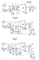
- the pressure regulator 4 is at two points 31 and 32 is connected to the exhaust gas stream 3, with an aperture 30 or a other means that is dependent on the mass flow to produce a Pressure difference is suitable between the two connection points 31, 32 of the Pressure regulator 4 is arranged.
- the side connection c is closed.
- a valve 8 is connected in parallel with the connection points 31, 32, with which the gas differential pressure acting on the pressure regulator 4 can be changed.
- the controller 50 of the mass flow sensor 5 and via a signal line 85 the valve 8 can be controlled so that the gas flow 2 remains constant. In only small gas flows are let through the valve 8, so that the Use of a micro proportional valve is advantageous. But it can also an ordinary valve can be used if it is operated clocked becomes.
- the inertia of the pressure regulator membrane 40 prevents oscillation.
- FIG. 7 the opening side of the pressure regulator 4, Port a, connected to the exhaust gas stream 3, namely to a Junction 31, at which a diaphragm 33 is arranged downstream there is increased pressure.
- the closing one Side of the pressure regulator 4 connected to the outlet of the valve 22 (Connection c to d).
- the pressure at the connection points 31 must be so high be that there is a pressure difference with respect to port d.
- On Drain valve 9 is between the connection point 31 on the exhaust gas flow 3 and the Pressure regulator 4 arranged with which the acting on the pressure regulator Pressure difference in an analogous manner as in the other examples using the Mass flow controller 50 (signal line 95) can be changed.
- the actuator 19 can be a valve, a control valve or be a fan.
- the first educt stream 1 is in front of the battery input 13a performed in two parts 1a and 1b.
- One part of the first educt stream 1 is referred to below as minimal air flow 1a, the other part withdeluftstrom1b.
- the device 20, which contains the pressure regulator 4 the minimum air flow 1a in a constant ratio to the second educt stream 2 fed to the battery input 13a.
- the cooling air flow 1 b of the first educt stream 1 is used to regulate the reaction temperature controlled.
- the quantity ratio mentioned is determined by means of the pressure regulator 4 kept constant in such a way that the air ratio ⁇ for each cooling air flow 1b is greater than one.
- An element 17 for example Venturi nozzle, orifice, "linear flow element" arranged one Leading pressure generated. Element 17 is with pressure regulator 4 connected so that the guide pressure via port a the second Educt stream 2 can affect.
- a mass flow sensor 18 With a mass flow sensor 18, the Cooling air flow 1b measured and a corresponding signal to the Control device 14c are transmitted. With the mass flow sensor 5 in the second educt stream 2 is another signal for the Control device 14c generated.
- controllers namely direct controllers or cascade controllers, which are components of the control device 14c, the two educt streams 1 and 2 can be set.
- the Mass flow sensor 18 is only required for the cascade controller concept.
- the Mass flow sensor 5 can alternatively also in the minimum air flow 1a are located. Due to the constant ⁇ ratio, the second can Educt stream 2 can be calculated.
- the Reaction temperature controlled the actuator 19 with a first controller.
- a second controller that sets a target value for the second educt stream 2 with an actual value measured by the mass flow sensor 5, the fan 16 is driven.
- the Reaction temperature with a first controller a setpoint for the cooling air 1b determined in a second controller with a by the Mass flow sensor 18 measured actual value is compared, a first Output signal is generated.
- a second output signal is sent with a third controller that generates a setpoint for the second educt stream 2 compares an actual value measured by the mass flow sensor 5.
- the two output signals are control variables for the blower 16 and the actuator 19 determines and these system components controlled accordingly. For the control of the fan 16, the added two output signals; for driving the actuator 19 a quotient is formed from the output signals.
Landscapes
- Life Sciences & Earth Sciences (AREA)
- Engineering & Computer Science (AREA)
- Manufacturing & Machinery (AREA)
- Sustainable Development (AREA)
- Sustainable Energy (AREA)
- Chemical & Material Sciences (AREA)
- Chemical Kinetics & Catalysis (AREA)
- Electrochemistry (AREA)
- General Chemical & Material Sciences (AREA)
- Fuel Cell (AREA)
Abstract
Description
- Fig. 1
- eine schematische Darstellung einer Anlage mit Brennstoffzellen, in der das erfindungsgemässe Verfahren angewendet werden soll,
- Fig. 2
- eine pneumatische Einrichtung, wie sie bereits für Gebläsebrenner verwendet wird,
- Fig. 3
- eine symbolische Darstellung der Einrichtung der Fig. 2,
- Fig. 4
- ein Schaltungsschema zu einer Anlage, in der eine erste Ausführungsform des erfindungsgemässen Verfahrens angewendet wird,
- Fig. 5 - 7
- jeweils ein Schaltungsschema zu drei weiteren Ausführungsformen und
- Fig. 8
- ein Schaltungsschema zu einer Ausführungsform des erfindungsgemässen Verfahrens, bei der auf den ersten Eduktstrom mit einem Stellglied eingewirkt wird.
Claims (10)
- Verfahren zum Betreiben einer Brennstoffzellenbatterie (10) mit einer Steuerung (14), durch die elektrochemische Reaktionen in Zellen (11) der Batterie beeinflusst werden,
in welchem Verfahren gasförmige Ströme (1, 2) zweier Edukte (A, B) in einem bedingt vorgebenen Mengenverhältnis gesteuert in die Batterie eingespeist und getrennt durch die Zellen geführt werden,
das erste Edukt (A) oxidierende Komponenten, das zweite Edukt (B) reduzierende Komponenten enthält und das erste Edukt insbesondere Umgebungsluft ist,
und die Eduktströme (1, 2) nach Durchgang durch die Zellen vereinigt und mittels einer Nachverbrennung und unter Erzeugung eines Stroms (3) von Abgas (C) weiter behandelt werden, so dass bei dem bedingt vorgebenen Mengenverhältnis die reduzierenden Komponenten vollständig oxidiert werden,
wobei der erste Eduktstrom, insbesondere der Luftstrom, durch die Steuerung in beschränktem Mass variierbar ist und zu einer Regelung der Reaktionstemperatur verwendet wird,
und - simultan zur Regelung der Reaktionstemperatur - der zweite Eduktstrom konstant gehalten wird, nämlich mittels einer zweiten Regelung (5, 6; 18, 19), die auf einen der Eduktströme vor dem Batterieeingang (13a, 13b) einwirkt. - Verfahren nach Anspruch 1, dadurch gekennzeichnet, dass die Eduktströme (1, 2) durch Absaugen des Abgases (C) mittels eines drehzahlgesteuerten Gebläses (16) angetrieben werden und dass die Reaktionstemperatur mittels Änderungen der Gebläsedrehzahl geregelt wird.
- Verfahren nach Anspruch 1 oder 2, dadurch gekennzeichnet, dass der zweite Eduktstrom (2) vor dem Batterieeingang mit einem Ventil (22) und einem weiteren Organ (6; 7; 8; 9) beeinflusst wird, wobei das Ventil durch einen Druckregler (4) gesteuert wird, der an eine Zuführleitung (c) des zweiten Edukts (B) und/oder an einen Abgasstrom (3) angeschlossen ist, und das weitere Organ mittels eines Massenstromsensors (5) sowie eines Reglers (50) gesteuert wird.
- Verfahren nach Anspruch 3, dadurch gekennzeichnet, dass der Druckregler (4) mit einem Reservoir (1') des ersten Edukts (A), insbesondere mit Umgebungsluft, und mit dem zweiten Eduktstrom (2) am Ventilausgang (c) verbunden ist, so dass sich aufgrund der Steuerung des Ventils (22) ein konstantes Verhältnis von Reservoirdruck (pA) zum Druck (pB) am Ventilausgang einstellt, und dass als weiteres Organ ein Proportionalventil (6) verwendet wird, das stromabwärts nach dem Ventil (22) des Druckreglers angeordnet ist.
- Verfahren nach Anspruch 3, dadurch gekennzeichnet, dass der Druckregler (4) mit einem Reservoir (1') des ersten Edukts (A) und mit dem zweiten Eduktstrom (2) am Ventilausgang (c) verbunden ist und dass als weiteres Organ ein Hilfslüfter (7) verwendet wird, der zwischen dem Druckregler und dem Reservoir angeordnet ist.
- Verfahren nach Anspruch 3, dadurch gekennzeichnet, dass der Druckregler (4, a, d) an zwei Stellen (31, 32) an den Abgasstrom (3) angeschlossen ist, dass eine Blende (30) oder ein anderes Mittel zur Erzeugung einer vom Massenstrom abhängigen Durckdifferenz zwischen den zwei Anschlussstellen (a, d oder 31, 32) des Druckreglers angeordnet ist und dass als weiteres Organ ein parallel zum Druckregler angeschlossenes Ventil (8) verwendet wird, mit dem die auf den Druckregler wirkende Durckdifferenz veränderbar ist.
- Verfahren nach Anspruch 3, dadurch gekennzeichnet, dass die öffnende Seite (a) des Druckreglers (4, a, d) an den Abgasstrom (3, 31) und die schliessende Seite (d) an den Ausgang (c) des regelbaren Ventils des zweiten Edukts (B) angeschlossen ist, wobei mittels geeigneter Mittel, insbesondere Blenden (33), eine Druckdifferenz zwischen den beiden Anschlussstellen (a, d) erzeugt wird, und dass als weiteres Organ ein Ablassventil (9) zwischen der Anschlussstelle (31) des Abgasstroms (3) und dem Druckregler (4, a) verwendet wird, mit dem der auf den Druckregler wirkende Gasdifferenzdurck veränderbar ist.
- Verfahren nach einem der Ansprüche 1 bis 7, dadurch gekennzeichnet, dass Mittel zur Durchführung der zweiten Regelung aufgrund einer Qualitätsänderung des zweiten Edukts (B) beeinflussbar sind, dass die Qualität des zweiten Edukts durch einen Parameter charakterisierbar ist, dass ein Sensor zum Messen dieses charakteristischen Parameters im zweiten Eduktstrom (2) oder im Abgasstrom angeordnet ist und dass eine Änderung des charakteristischen Parameters für eine Beeinflussung der zweiten Regelung verwendet wird.
- Verfahren nach Anspruch 1 oder 2, dadurch gekennzeichnet, dass der erste Eduktstrom (1) vor dem Batterieeingang (13a) in zwei Teilen (1a, 1b) zugeführt wird, der eine Teil (1a) des erste Eduktstromsinsbesondere ein Minimalluftstrom - in einem konstanten Mengenverhältnis zum zweiten Eduktstrom (2) zugeführt wird und der andere Teil (1b) des ersten Eduktstroms zwecks Regelung der Reaktionstemperatur gesteuert wird, wobei das genannte Mengenverhältnis mittels einem Druckregler (4) konstant gehalten wird und zwar so, dass die Luftzahl λ immer grösser als eins ist.
- Anlage mit Brennstoffzellenbatterie (10) und einer Steuerung (14) gemäss einem der Verfahren der Ansprüche 1 bis 9, dadurch gekennzeichnet, dass ein Druckregler (4) und Zuführleitungen für die Edukte (A, B) Teile eines pneumatischen oder elektropneumatischen Verbunds sind, dass der Druckregler einen Behälter mit zwei durch eine Membran (40) unterteilte Kammern (41, 42) umfasst, die Membran mit einem zu steuernden Ventil (22) verbunden ist und der Druckregler ein Gleichdruckregler oder ein Verhältnisdruckregler sein kann.
Priority Applications (1)
| Application Number | Priority Date | Filing Date | Title |
|---|---|---|---|
| EP01810984A EP1205993B1 (de) | 2000-11-07 | 2001-10-09 | Verfahren zur Betreiben einer Brennstoffzellenbatterie mit einer Steuerung |
Applications Claiming Priority (3)
| Application Number | Priority Date | Filing Date | Title |
|---|---|---|---|
| EP00811042 | 2000-11-07 | ||
| EP00811042 | 2000-11-07 | ||
| EP01810984A EP1205993B1 (de) | 2000-11-07 | 2001-10-09 | Verfahren zur Betreiben einer Brennstoffzellenbatterie mit einer Steuerung |
Publications (2)
| Publication Number | Publication Date |
|---|---|
| EP1205993A1 true EP1205993A1 (de) | 2002-05-15 |
| EP1205993B1 EP1205993B1 (de) | 2012-12-05 |
Family
ID=26074072
Family Applications (1)
| Application Number | Title | Priority Date | Filing Date |
|---|---|---|---|
| EP01810984A Expired - Lifetime EP1205993B1 (de) | 2000-11-07 | 2001-10-09 | Verfahren zur Betreiben einer Brennstoffzellenbatterie mit einer Steuerung |
Country Status (1)
| Country | Link |
|---|---|
| EP (1) | EP1205993B1 (de) |
Cited By (11)
| Publication number | Priority date | Publication date | Assignee | Title |
|---|---|---|---|---|
| EP1396896A1 (de) * | 2002-09-04 | 2004-03-10 | Sulzer Hexis AG | Raumheizungsystem mit Brennstoffzellen und Anschluss an ein öffentliches elektrisches Netz |
| FR2845524A1 (fr) * | 2002-10-03 | 2004-04-09 | Renault Sa | Procede de regulation du debit d'air dans une pile a combustible |
| WO2004046841A1 (en) * | 2002-11-20 | 2004-06-03 | Greenlight Power Technologies, Inc. | Inspirated pressure control system |
| US6794070B2 (en) | 2001-11-24 | 2004-09-21 | Robert Bosch Gmbh | Fuel cell apparatus with compressor means for reducing fuel leakage danger and improving efficiency |
| US6935363B2 (en) | 2002-11-20 | 2005-08-30 | Hydrogenics Corporation | Pressure control system for low pressure operation |
| WO2008064628A1 (de) * | 2006-11-29 | 2008-06-05 | Enerday Gmbh | Verfahren zum steuern eines einer klimaanlage zugeordneten brennstoffzellensystems und klimaanlage zur standklimatisierung eines kraftfahrzeugs |
| EP2658021A1 (de) | 2012-04-27 | 2013-10-30 | Hexis AG | Verfahren und Regelvorrichtung zur Regelung einer Brennstoffzelle oder eines Brennstoffzellenstapels |
| EP2800190A1 (de) | 2013-04-18 | 2014-11-05 | Hexis AG | Verfahren und Regelvorrichtung zum Betreiben einer Brennstoffzelle oder eines Brennstoffzellenstapels |
| EP2824743A1 (de) | 2013-07-08 | 2015-01-14 | Vaillant GmbH | Verfahren zur Regelung einer Brennstoffzelle |
| EP3024077A1 (de) * | 2014-11-18 | 2016-05-25 | Hexis AG | Einrichtung und verfahren zur versorgung einer brennstoffzellenbatterie |
| EP3024076A1 (de) | 2014-11-18 | 2016-05-25 | Hexis AG | Einrichtung und Verfahren zur Versorgung einer Brennstoffzellenbatterie |
Citations (5)
| Publication number | Priority date | Publication date | Assignee | Title |
|---|---|---|---|---|
| EP0377151A1 (de) * | 1989-01-04 | 1990-07-11 | Asea Brown Boveri Ag | Verfahren zur selbsttätigen Temperatur- und Leistungsregulierung einer oder mehrerer, mit Kohlenwasserstoffen betriebenen Hochtemperatur-Brennstoffzellen |
| DE4037970A1 (de) * | 1989-12-21 | 1991-06-27 | Asea Brown Boveri | Verfahren zur selbsttaetigen inbetriebsetzung einer oder mehrerer, mit kohlenwasserstoffen betriebenen hochtemperatur-brennstoffzellen |
| EP0780917A1 (de) * | 1995-12-19 | 1997-06-25 | Sulzer Innotec Ag | Vorrichtung mit Brennstoffzellen |
| EP0818840A1 (de) * | 1996-07-11 | 1998-01-14 | Sulzer Hexis AG | Verfahren zur gleichzeitigen Erzeugung von elektrischer Energie und Wärme für Heizzwecke |
| US6136462A (en) * | 1997-02-21 | 2000-10-24 | Aeg Energietechnik Gmbh | High temperature fuel cells with heating of the reaction gas |
-
2001
- 2001-10-09 EP EP01810984A patent/EP1205993B1/de not_active Expired - Lifetime
Patent Citations (5)
| Publication number | Priority date | Publication date | Assignee | Title |
|---|---|---|---|---|
| EP0377151A1 (de) * | 1989-01-04 | 1990-07-11 | Asea Brown Boveri Ag | Verfahren zur selbsttätigen Temperatur- und Leistungsregulierung einer oder mehrerer, mit Kohlenwasserstoffen betriebenen Hochtemperatur-Brennstoffzellen |
| DE4037970A1 (de) * | 1989-12-21 | 1991-06-27 | Asea Brown Boveri | Verfahren zur selbsttaetigen inbetriebsetzung einer oder mehrerer, mit kohlenwasserstoffen betriebenen hochtemperatur-brennstoffzellen |
| EP0780917A1 (de) * | 1995-12-19 | 1997-06-25 | Sulzer Innotec Ag | Vorrichtung mit Brennstoffzellen |
| EP0818840A1 (de) * | 1996-07-11 | 1998-01-14 | Sulzer Hexis AG | Verfahren zur gleichzeitigen Erzeugung von elektrischer Energie und Wärme für Heizzwecke |
| US6136462A (en) * | 1997-02-21 | 2000-10-24 | Aeg Energietechnik Gmbh | High temperature fuel cells with heating of the reaction gas |
Cited By (16)
| Publication number | Priority date | Publication date | Assignee | Title |
|---|---|---|---|---|
| US6794070B2 (en) | 2001-11-24 | 2004-09-21 | Robert Bosch Gmbh | Fuel cell apparatus with compressor means for reducing fuel leakage danger and improving efficiency |
| EP1396896A1 (de) * | 2002-09-04 | 2004-03-10 | Sulzer Hexis AG | Raumheizungsystem mit Brennstoffzellen und Anschluss an ein öffentliches elektrisches Netz |
| US7021553B2 (en) | 2002-09-04 | 2006-04-04 | Sulzer Hexis Ag | Space heating system with fuel cells and a connection to a public electrical network |
| FR2845524A1 (fr) * | 2002-10-03 | 2004-04-09 | Renault Sa | Procede de regulation du debit d'air dans une pile a combustible |
| WO2004032268A2 (fr) * | 2002-10-03 | 2004-04-15 | Renault S.A.S. | Procede de regulation du debit d'air dans une pile a combustible |
| WO2004032268A3 (fr) * | 2002-10-03 | 2005-03-03 | Renault Sa | Procede de regulation du debit d'air dans une pile a combustible |
| WO2004046841A1 (en) * | 2002-11-20 | 2004-06-03 | Greenlight Power Technologies, Inc. | Inspirated pressure control system |
| US6935363B2 (en) | 2002-11-20 | 2005-08-30 | Hydrogenics Corporation | Pressure control system for low pressure operation |
| WO2008064628A1 (de) * | 2006-11-29 | 2008-06-05 | Enerday Gmbh | Verfahren zum steuern eines einer klimaanlage zugeordneten brennstoffzellensystems und klimaanlage zur standklimatisierung eines kraftfahrzeugs |
| EP1939966A1 (de) * | 2006-11-29 | 2008-07-02 | Enerday GmbH | Verfahren zum Steuern eines einer Klimaanlage zugeordneten Brennstoffzellensystems und Klimaanlage zur Standklimatisierung eines Kraftfahrzeugs |
| EP2658021A1 (de) | 2012-04-27 | 2013-10-30 | Hexis AG | Verfahren und Regelvorrichtung zur Regelung einer Brennstoffzelle oder eines Brennstoffzellenstapels |
| EP2800190A1 (de) | 2013-04-18 | 2014-11-05 | Hexis AG | Verfahren und Regelvorrichtung zum Betreiben einer Brennstoffzelle oder eines Brennstoffzellenstapels |
| EP2824743A1 (de) | 2013-07-08 | 2015-01-14 | Vaillant GmbH | Verfahren zur Regelung einer Brennstoffzelle |
| EP3024077A1 (de) * | 2014-11-18 | 2016-05-25 | Hexis AG | Einrichtung und verfahren zur versorgung einer brennstoffzellenbatterie |
| EP3024076A1 (de) | 2014-11-18 | 2016-05-25 | Hexis AG | Einrichtung und Verfahren zur Versorgung einer Brennstoffzellenbatterie |
| US10411276B2 (en) | 2014-11-18 | 2019-09-10 | Hexis Ag | Device and method for supplying a fuel cell battery |
Also Published As
| Publication number | Publication date |
|---|---|
| EP1205993B1 (de) | 2012-12-05 |
Similar Documents
| Publication | Publication Date | Title |
|---|---|---|
| DE112006003292B4 (de) | Brennstoffzellensystem und Verwendung des Brennstoffzellelsystems in einem beweglichen Gegenstand | |
| DE112015003129B4 (de) | Brennstoffzellensystem und Verfahren für ein Steuern eines Brennstoffzellensystems | |
| EP1205993B1 (de) | Verfahren zur Betreiben einer Brennstoffzellenbatterie mit einer Steuerung | |
| AT518518B1 (de) | Geregelte Gaskonditionierung für ein Reaktionsgas einer Brennstoffzelle | |
| DE112007002858B4 (de) | Brennstoffzellensystem mit einer Steuereinheit zum Ansteuern von Ventilen unter Verwendung des Drucks eines durch einen Fluidströmungsweg strömenden Fluids | |
| DE102006058834B4 (de) | System und Verfahren zum Steuern der relativen Feuchte einer Kathodeneingangsluftströmung zu einem Brennstoffzellenstapel | |
| DE2157722A1 (de) | Elektronischer Proportionalregler zur Regelung der Brennstoffzufuhr bei Brennstoffzellen | |
| DE102006005175A1 (de) | Vorrichtung und Verfahren zur Kontrolle des Differenzdrucks in einer Brennstoffzelle | |
| DE19517813C2 (de) | Verfahren zur Regelung des wärmegeführten Betriebes von Brennstoffzellenanlagen | |
| EP2843214B1 (de) | Verfahren, Sensor und Regelvorrichtung zur Regelung gasbetriebener Energiewandleranlagen | |
| DE10297104B4 (de) | Verfahren und Voprrichtung zur elektrischen Leistungsregelung eines Brennstoffzellensystems | |
| DE102006042107A1 (de) | Brennstoffzellensystem und Verfahren zum Beeinflussen des Wärme- und Temperaturhaushaltes eines Brennstoffzellenstapels | |
| EP2033255A1 (de) | Brennstoffzellensystem | |
| JP2002184444A (ja) | 制御システムを有する燃料セル電池を作動する方法およびそれらを含むプラント | |
| DE102018200350A1 (de) | Brennstoffzellenanordnung für eine H2/O2-Brennstoffzelle | |
| AT522319B1 (de) | Brennstoffzellensystem, Verfahren zum Betreiben eines Brennstoffzellensystems und Brennstoffzellenfahrzeug | |
| DE102008010711B4 (de) | Verfahren zum Betreiben eines Brennstoffzellensystems sowie Brennstoffzellensystem mit einer Regleranordnung | |
| DE102011122162A1 (de) | Brennstoffzellenvorrichtung | |
| DE19526774A1 (de) | Verfahren zum Betreiben einer Brennstoffzellenanlage und Brennstoffzellenanlage zum Durchführen des Verfahrens | |
| DE102022201049A1 (de) | Brennstoffzellenvorrichtung und Verfahren zum Regulieren wenigstens einer Stacktemperatur einer Brennstoffzellenvorrichtung | |
| DE10010394A1 (de) | Brennstoffzelle | |
| WO2019028487A1 (de) | Brennstoffzellensystem mit zumindest einer hochtemperatur-brennstoffzelle | |
| DE102022201060A1 (de) | Brennstoffzellenvorrichtung und Verfahren zum Regulieren wenigstens einer Stacktemperatur einer Brennstoffzellenvorrichtung | |
| DE102009006159A1 (de) | Steuerung/Regelung einer Temperatur einer Brennstoffzelle | |
| EP2061584A1 (de) | Verfahren und system zur regelung/steuerung einer gesamtluftverhältniszahl eines reformers |
Legal Events
| Date | Code | Title | Description |
|---|---|---|---|
| PUAI | Public reference made under article 153(3) epc to a published international application that has entered the european phase |
Free format text: ORIGINAL CODE: 0009012 |
|
| AK | Designated contracting states |
Kind code of ref document: A1 Designated state(s): AT BE CH CY DE DK ES FI FR GB GR IE IT LI LU MC NL PT SE TR |
|
| AX | Request for extension of the european patent |
Free format text: AL;LT;LV;MK;RO;SI |
|
| 17P | Request for examination filed |
Effective date: 20021017 |
|
| AKX | Designation fees paid |
Designated state(s): AT BE CH CY DE DK ES FI FR GB GR IE IT LI LU MC NL PT SE TR |
|
| RAP1 | Party data changed (applicant data changed or rights of an application transferred) |
Owner name: HEXIS AG |
|
| 17Q | First examination report despatched |
Effective date: 20100512 |
|
| GRAP | Despatch of communication of intention to grant a patent |
Free format text: ORIGINAL CODE: EPIDOSNIGR1 |
|
| GRAS | Grant fee paid |
Free format text: ORIGINAL CODE: EPIDOSNIGR3 |
|
| GRAA | (expected) grant |
Free format text: ORIGINAL CODE: 0009210 |
|
| AK | Designated contracting states |
Kind code of ref document: B1 Designated state(s): AT BE CH CY DE DK ES FI FR GB GR IE IT LI LU MC NL PT SE TR |
|
| REG | Reference to a national code |
Ref country code: GB Ref legal event code: FG4D Free format text: NOT ENGLISH |
|
| REG | Reference to a national code |
Ref country code: CH Ref legal event code: EP Ref country code: CH Ref legal event code: NV Representative=s name: SULZER MANAGEMENT AG PATENTABTEILUNG/0067, CH |
|
| REG | Reference to a national code |
Ref country code: AT Ref legal event code: REF Ref document number: 587692 Country of ref document: AT Kind code of ref document: T Effective date: 20121215 |
|
| REG | Reference to a national code |
Ref country code: IE Ref legal event code: FG4D Free format text: LANGUAGE OF EP DOCUMENT: GERMAN |
|
| REG | Reference to a national code |
Ref country code: DE Ref legal event code: R096 Ref document number: 50116208 Country of ref document: DE Effective date: 20130131 |
|
| REG | Reference to a national code |
Ref country code: DK Ref legal event code: T3 |
|
| REG | Reference to a national code |
Ref country code: NL Ref legal event code: T3 |
|
| PG25 | Lapsed in a contracting state [announced via postgrant information from national office to epo] |
Ref country code: FI Free format text: LAPSE BECAUSE OF FAILURE TO SUBMIT A TRANSLATION OF THE DESCRIPTION OR TO PAY THE FEE WITHIN THE PRESCRIBED TIME-LIMIT Effective date: 20121205 Ref country code: SE Free format text: LAPSE BECAUSE OF FAILURE TO SUBMIT A TRANSLATION OF THE DESCRIPTION OR TO PAY THE FEE WITHIN THE PRESCRIBED TIME-LIMIT Effective date: 20121205 Ref country code: ES Free format text: LAPSE BECAUSE OF FAILURE TO SUBMIT A TRANSLATION OF THE DESCRIPTION OR TO PAY THE FEE WITHIN THE PRESCRIBED TIME-LIMIT Effective date: 20130316 |
|
| PG25 | Lapsed in a contracting state [announced via postgrant information from national office to epo] |
Ref country code: GR Free format text: LAPSE BECAUSE OF FAILURE TO SUBMIT A TRANSLATION OF THE DESCRIPTION OR TO PAY THE FEE WITHIN THE PRESCRIBED TIME-LIMIT Effective date: 20130306 Ref country code: CY Free format text: LAPSE BECAUSE OF FAILURE TO SUBMIT A TRANSLATION OF THE DESCRIPTION OR TO PAY THE FEE WITHIN THE PRESCRIBED TIME-LIMIT Effective date: 20121205 |
|
| PG25 | Lapsed in a contracting state [announced via postgrant information from national office to epo] |
Ref country code: PT Free format text: LAPSE BECAUSE OF FAILURE TO SUBMIT A TRANSLATION OF THE DESCRIPTION OR TO PAY THE FEE WITHIN THE PRESCRIBED TIME-LIMIT Effective date: 20130405 |
|
| PLBE | No opposition filed within time limit |
Free format text: ORIGINAL CODE: 0009261 |
|
| STAA | Information on the status of an ep patent application or granted ep patent |
Free format text: STATUS: NO OPPOSITION FILED WITHIN TIME LIMIT |
|
| 26N | No opposition filed |
Effective date: 20130906 |
|
| REG | Reference to a national code |
Ref country code: DE Ref legal event code: R097 Ref document number: 50116208 Country of ref document: DE Effective date: 20130906 |
|
| REG | Reference to a national code |
Ref country code: CH Ref legal event code: NV Representative=s name: INTELLECTUAL PROPERTY SERVICES GMBH, CH |
|
| REG | Reference to a national code |
Ref country code: CH Ref legal event code: PCAR Free format text: NEW ADDRESS: LANGFELDSTRASSE 88, 8500 FRAUENFELD (CH) |
|
| BERE | Be: lapsed |
Owner name: HEXIS A.G. Effective date: 20131031 |
|
| PG25 | Lapsed in a contracting state [announced via postgrant information from national office to epo] |
Ref country code: MC Free format text: LAPSE BECAUSE OF FAILURE TO SUBMIT A TRANSLATION OF THE DESCRIPTION OR TO PAY THE FEE WITHIN THE PRESCRIBED TIME-LIMIT Effective date: 20121205 |
|
| REG | Reference to a national code |
Ref country code: IE Ref legal event code: MM4A |
|
| PG25 | Lapsed in a contracting state [announced via postgrant information from national office to epo] |
Ref country code: BE Free format text: LAPSE BECAUSE OF NON-PAYMENT OF DUE FEES Effective date: 20131031 |
|
| PG25 | Lapsed in a contracting state [announced via postgrant information from national office to epo] |
Ref country code: IE Free format text: LAPSE BECAUSE OF NON-PAYMENT OF DUE FEES Effective date: 20131009 |
|
| PG25 | Lapsed in a contracting state [announced via postgrant information from national office to epo] |
Ref country code: TR Free format text: LAPSE BECAUSE OF FAILURE TO SUBMIT A TRANSLATION OF THE DESCRIPTION OR TO PAY THE FEE WITHIN THE PRESCRIBED TIME-LIMIT Effective date: 20121205 |
|
| PG25 | Lapsed in a contracting state [announced via postgrant information from national office to epo] |
Ref country code: LU Free format text: LAPSE BECAUSE OF NON-PAYMENT OF DUE FEES Effective date: 20131009 |
|
| REG | Reference to a national code |
Ref country code: FR Ref legal event code: PLFP Year of fee payment: 15 |
|
| REG | Reference to a national code |
Ref country code: FR Ref legal event code: PLFP Year of fee payment: 16 |
|
| REG | Reference to a national code |
Ref country code: FR Ref legal event code: PLFP Year of fee payment: 17 |
|
| REG | Reference to a national code |
Ref country code: FR Ref legal event code: PLFP Year of fee payment: 18 |
|
| PGFP | Annual fee paid to national office [announced via postgrant information from national office to epo] |
Ref country code: NL Payment date: 20181019 Year of fee payment: 18 |
|
| PGFP | Annual fee paid to national office [announced via postgrant information from national office to epo] |
Ref country code: AT Payment date: 20181022 Year of fee payment: 18 Ref country code: DK Payment date: 20181023 Year of fee payment: 18 |
|
| PGFP | Annual fee paid to national office [announced via postgrant information from national office to epo] |
Ref country code: TR Payment date: 20181011 Year of fee payment: 11 |
|
| PGFP | Annual fee paid to national office [announced via postgrant information from national office to epo] |
Ref country code: DE Payment date: 20191021 Year of fee payment: 19 |
|
| PGFP | Annual fee paid to national office [announced via postgrant information from national office to epo] |
Ref country code: FR Payment date: 20191028 Year of fee payment: 19 Ref country code: IT Payment date: 20191028 Year of fee payment: 19 |
|
| PGFP | Annual fee paid to national office [announced via postgrant information from national office to epo] |
Ref country code: GB Payment date: 20191021 Year of fee payment: 19 |
|
| REG | Reference to a national code |
Ref country code: DK Ref legal event code: EBP Effective date: 20191031 |
|
| REG | Reference to a national code |
Ref country code: CH Ref legal event code: PL |
|
| REG | Reference to a national code |
Ref country code: NL Ref legal event code: MM Effective date: 20191101 |
|
| PG25 | Lapsed in a contracting state [announced via postgrant information from national office to epo] |
Ref country code: CH Free format text: LAPSE BECAUSE OF NON-PAYMENT OF DUE FEES Effective date: 20191031 Ref country code: LI Free format text: LAPSE BECAUSE OF NON-PAYMENT OF DUE FEES Effective date: 20191031 |
|
| REG | Reference to a national code |
Ref country code: AT Ref legal event code: MM01 Ref document number: 587692 Country of ref document: AT Kind code of ref document: T Effective date: 20191009 |
|
| PG25 | Lapsed in a contracting state [announced via postgrant information from national office to epo] |
Ref country code: NL Free format text: LAPSE BECAUSE OF NON-PAYMENT OF DUE FEES Effective date: 20191101 |
|
| PG25 | Lapsed in a contracting state [announced via postgrant information from national office to epo] |
Ref country code: DK Free format text: LAPSE BECAUSE OF NON-PAYMENT OF DUE FEES Effective date: 20191031 |
|
| PG25 | Lapsed in a contracting state [announced via postgrant information from national office to epo] |
Ref country code: AT Free format text: LAPSE BECAUSE OF NON-PAYMENT OF DUE FEES Effective date: 20191009 |
|
| REG | Reference to a national code |
Ref country code: DE Ref legal event code: R119 Ref document number: 50116208 Country of ref document: DE |
|
| GBPC | Gb: european patent ceased through non-payment of renewal fee |
Effective date: 20201009 |
|
| PG25 | Lapsed in a contracting state [announced via postgrant information from national office to epo] |
Ref country code: DE Free format text: LAPSE BECAUSE OF NON-PAYMENT OF DUE FEES Effective date: 20210501 Ref country code: FR Free format text: LAPSE BECAUSE OF NON-PAYMENT OF DUE FEES Effective date: 20201031 |
|
| PG25 | Lapsed in a contracting state [announced via postgrant information from national office to epo] |
Ref country code: GB Free format text: LAPSE BECAUSE OF NON-PAYMENT OF DUE FEES Effective date: 20201009 |
|
| PG25 | Lapsed in a contracting state [announced via postgrant information from national office to epo] |
Ref country code: IT Free format text: LAPSE BECAUSE OF NON-PAYMENT OF DUE FEES Effective date: 20201009 |