EP2524657B1 - Ensemble d'enclume à bas coût d'une agrafeuse circulaire - Google Patents
Ensemble d'enclume à bas coût d'une agrafeuse circulaire Download PDFInfo
- Publication number
- EP2524657B1 EP2524657B1 EP12168712.3A EP12168712A EP2524657B1 EP 2524657 B1 EP2524657 B1 EP 2524657B1 EP 12168712 A EP12168712 A EP 12168712A EP 2524657 B1 EP2524657 B1 EP 2524657B1
- Authority
- EP
- European Patent Office
- Prior art keywords
- anvil
- shaft
- assembly
- stapling instrument
- adjusting rod
- Prior art date
- Legal status (The legal status is an assumption and is not a legal conclusion. Google has not performed a legal analysis and makes no representation as to the accuracy of the status listed.)
- Active
Links
- 229910052751 metal Inorganic materials 0.000 claims description 74
- 239000002184 metal Substances 0.000 claims description 74
- 238000004519 manufacturing process Methods 0.000 claims description 14
- 238000000465 moulding Methods 0.000 claims description 12
- 229920000642 polymer Polymers 0.000 claims description 12
- 238000010304 firing Methods 0.000 description 132
- 230000007246 mechanism Effects 0.000 description 24
- 230000001681 protective effect Effects 0.000 description 23
- 230000008878 coupling Effects 0.000 description 22
- 238000010168 coupling process Methods 0.000 description 22
- 238000005859 coupling reaction Methods 0.000 description 22
- 238000005520 cutting process Methods 0.000 description 20
- 239000000463 material Substances 0.000 description 16
- 210000001519 tissue Anatomy 0.000 description 16
- 238000000034 method Methods 0.000 description 15
- 230000013011 mating Effects 0.000 description 9
- 229920001778 nylon Polymers 0.000 description 9
- OKTJSMMVPCPJKN-UHFFFAOYSA-N Carbon Chemical compound [C] OKTJSMMVPCPJKN-UHFFFAOYSA-N 0.000 description 8
- 239000004677 Nylon Substances 0.000 description 7
- 229910052799 carbon Inorganic materials 0.000 description 7
- 239000011521 glass Substances 0.000 description 7
- 229910001220 stainless steel Inorganic materials 0.000 description 7
- 230000000007 visual effect Effects 0.000 description 7
- 230000000712 assembly Effects 0.000 description 6
- 238000000429 assembly Methods 0.000 description 6
- 239000004033 plastic Substances 0.000 description 5
- 229920003023 plastic Polymers 0.000 description 5
- 239000010935 stainless steel Substances 0.000 description 5
- -1 Polyethylene Polymers 0.000 description 4
- 238000000576 coating method Methods 0.000 description 4
- 150000001875 compounds Chemical class 0.000 description 4
- 230000008569 process Effects 0.000 description 4
- 229910052782 aluminium Inorganic materials 0.000 description 3
- XAGFODPZIPBFFR-UHFFFAOYSA-N aluminium Chemical compound [Al] XAGFODPZIPBFFR-UHFFFAOYSA-N 0.000 description 3
- 238000005452 bending Methods 0.000 description 3
- 239000002131 composite material Substances 0.000 description 3
- 238000013461 design Methods 0.000 description 3
- 208000014617 hemorrhoid Diseases 0.000 description 3
- 238000002347 injection Methods 0.000 description 3
- 239000007924 injection Substances 0.000 description 3
- 230000014759 maintenance of location Effects 0.000 description 3
- 230000002265 prevention Effects 0.000 description 3
- 241000124008 Mammalia Species 0.000 description 2
- 239000004698 Polyethylene Substances 0.000 description 2
- 239000004743 Polypropylene Substances 0.000 description 2
- 230000003872 anastomosis Effects 0.000 description 2
- 229910000963 austenitic stainless steel Inorganic materials 0.000 description 2
- 230000004888 barrier function Effects 0.000 description 2
- 238000004140 cleaning Methods 0.000 description 2
- 238000010276 construction Methods 0.000 description 2
- 238000007373 indentation Methods 0.000 description 2
- 238000003780 insertion Methods 0.000 description 2
- 230000037431 insertion Effects 0.000 description 2
- 230000002452 interceptive effect Effects 0.000 description 2
- 238000003754 machining Methods 0.000 description 2
- 150000002739 metals Chemical class 0.000 description 2
- 229920000573 polyethylene Polymers 0.000 description 2
- 229920001155 polypropylene Polymers 0.000 description 2
- 230000001954 sterilising effect Effects 0.000 description 2
- 238000001356 surgical procedure Methods 0.000 description 2
- 238000012800 visualization Methods 0.000 description 2
- IQVNEKKDSLOHHK-FNCQTZNRSA-N (E,E)-hydramethylnon Chemical compound N1CC(C)(C)CNC1=NN=C(/C=C/C=1C=CC(=CC=1)C(F)(F)F)\C=C\C1=CC=C(C(F)(F)F)C=C1 IQVNEKKDSLOHHK-FNCQTZNRSA-N 0.000 description 1
- 229910000831 Steel Inorganic materials 0.000 description 1
- 239000004809 Teflon Substances 0.000 description 1
- 229920006362 Teflon® Polymers 0.000 description 1
- 239000004411 aluminium Substances 0.000 description 1
- 210000000436 anus Anatomy 0.000 description 1
- 230000008901 benefit Effects 0.000 description 1
- 230000000903 blocking effect Effects 0.000 description 1
- 230000003749 cleanliness Effects 0.000 description 1
- 239000002537 cosmetic Substances 0.000 description 1
- 230000007423 decrease Effects 0.000 description 1
- 230000002550 fecal effect Effects 0.000 description 1
- 229910002804 graphite Inorganic materials 0.000 description 1
- 239000010439 graphite Substances 0.000 description 1
- 238000012423 maintenance Methods 0.000 description 1
- 210000004400 mucous membrane Anatomy 0.000 description 1
- 239000004417 polycarbonate Substances 0.000 description 1
- 229920000515 polycarbonate Polymers 0.000 description 1
- 210000000664 rectum Anatomy 0.000 description 1
- 230000009467 reduction Effects 0.000 description 1
- 239000007787 solid Substances 0.000 description 1
- 239000010959 steel Substances 0.000 description 1
- 238000004659 sterilization and disinfection Methods 0.000 description 1
- 238000012414 sterilization procedure Methods 0.000 description 1
Images


Classifications
-
- A—HUMAN NECESSITIES
- A61—MEDICAL OR VETERINARY SCIENCE; HYGIENE
- A61B—DIAGNOSIS; SURGERY; IDENTIFICATION
- A61B17/00—Surgical instruments, devices or methods, e.g. tourniquets
- A61B17/11—Surgical instruments, devices or methods, e.g. tourniquets for performing anastomosis; Buttons for anastomosis
- A61B17/115—Staplers for performing anastomosis in a single operation
-
- H—ELECTRICITY
- H04—ELECTRIC COMMUNICATION TECHNIQUE
- H04B—TRANSMISSION
- H04B7/00—Radio transmission systems, i.e. using radiation field
- H04B7/02—Diversity systems; Multi-antenna system, i.e. transmission or reception using multiple antennas
- H04B7/04—Diversity systems; Multi-antenna system, i.e. transmission or reception using multiple antennas using two or more spaced independent antennas
- H04B7/06—Diversity systems; Multi-antenna system, i.e. transmission or reception using multiple antennas using two or more spaced independent antennas at the transmitting station
- H04B7/0613—Diversity systems; Multi-antenna system, i.e. transmission or reception using multiple antennas using two or more spaced independent antennas at the transmitting station using simultaneous transmission
- H04B7/0667—Diversity systems; Multi-antenna system, i.e. transmission or reception using multiple antennas using two or more spaced independent antennas at the transmitting station using simultaneous transmission of delayed versions of same signal
- H04B7/0673—Diversity systems; Multi-antenna system, i.e. transmission or reception using multiple antennas using two or more spaced independent antennas at the transmitting station using simultaneous transmission of delayed versions of same signal using feedback from receiving side
-
- A—HUMAN NECESSITIES
- A61—MEDICAL OR VETERINARY SCIENCE; HYGIENE
- A61B—DIAGNOSIS; SURGERY; IDENTIFICATION
- A61B17/00—Surgical instruments, devices or methods, e.g. tourniquets
- A61B17/068—Surgical staplers, e.g. containing multiple staples or clamps
- A61B17/0682—Surgical staplers, e.g. containing multiple staples or clamps for applying U-shaped staples or clamps, e.g. without a forming anvil
- A61B17/0684—Surgical staplers, e.g. containing multiple staples or clamps for applying U-shaped staples or clamps, e.g. without a forming anvil having a forming anvil staying above the tissue during stapling
-
- A—HUMAN NECESSITIES
- A61—MEDICAL OR VETERINARY SCIENCE; HYGIENE
- A61B—DIAGNOSIS; SURGERY; IDENTIFICATION
- A61B17/00—Surgical instruments, devices or methods, e.g. tourniquets
- A61B17/068—Surgical staplers, e.g. containing multiple staples or clamps
-
- A—HUMAN NECESSITIES
- A61—MEDICAL OR VETERINARY SCIENCE; HYGIENE
- A61B—DIAGNOSIS; SURGERY; IDENTIFICATION
- A61B17/00—Surgical instruments, devices or methods, e.g. tourniquets
- A61B17/068—Surgical staplers, e.g. containing multiple staples or clamps
- A61B17/072—Surgical staplers, e.g. containing multiple staples or clamps for applying a row of staples in a single action, e.g. the staples being applied simultaneously
- A61B17/07292—Reinforcements for staple line, e.g. pledgets
-
- A—HUMAN NECESSITIES
- A61—MEDICAL OR VETERINARY SCIENCE; HYGIENE
- A61B—DIAGNOSIS; SURGERY; IDENTIFICATION
- A61B17/00—Surgical instruments, devices or methods, e.g. tourniquets
- A61B17/11—Surgical instruments, devices or methods, e.g. tourniquets for performing anastomosis; Buttons for anastomosis
- A61B17/1114—Surgical instruments, devices or methods, e.g. tourniquets for performing anastomosis; Buttons for anastomosis of the digestive tract, e.g. bowels or oesophagus
-
- A—HUMAN NECESSITIES
- A61—MEDICAL OR VETERINARY SCIENCE; HYGIENE
- A61B—DIAGNOSIS; SURGERY; IDENTIFICATION
- A61B17/00—Surgical instruments, devices or methods, e.g. tourniquets
- A61B17/11—Surgical instruments, devices or methods, e.g. tourniquets for performing anastomosis; Buttons for anastomosis
- A61B17/115—Staplers for performing anastomosis in a single operation
- A61B17/1155—Circular staplers comprising a plurality of staples
-
- H—ELECTRICITY
- H04—ELECTRIC COMMUNICATION TECHNIQUE
- H04B—TRANSMISSION
- H04B7/00—Radio transmission systems, i.e. using radiation field
- H04B7/02—Diversity systems; Multi-antenna system, i.e. transmission or reception using multiple antennas
- H04B7/04—Diversity systems; Multi-antenna system, i.e. transmission or reception using multiple antennas using two or more spaced independent antennas
- H04B7/06—Diversity systems; Multi-antenna system, i.e. transmission or reception using multiple antennas using two or more spaced independent antennas at the transmitting station
- H04B7/0613—Diversity systems; Multi-antenna system, i.e. transmission or reception using multiple antennas using two or more spaced independent antennas at the transmitting station using simultaneous transmission
- H04B7/0667—Diversity systems; Multi-antenna system, i.e. transmission or reception using multiple antennas using two or more spaced independent antennas at the transmitting station using simultaneous transmission of delayed versions of same signal
- H04B7/0671—Diversity systems; Multi-antenna system, i.e. transmission or reception using multiple antennas using two or more spaced independent antennas at the transmitting station using simultaneous transmission of delayed versions of same signal using different delays between antennas
-
- H—ELECTRICITY
- H04—ELECTRIC COMMUNICATION TECHNIQUE
- H04B—TRANSMISSION
- H04B7/00—Radio transmission systems, i.e. using radiation field
- H04B7/02—Diversity systems; Multi-antenna system, i.e. transmission or reception using multiple antennas
- H04B7/04—Diversity systems; Multi-antenna system, i.e. transmission or reception using multiple antennas using two or more spaced independent antennas
- H04B7/06—Diversity systems; Multi-antenna system, i.e. transmission or reception using multiple antennas using two or more spaced independent antennas at the transmitting station
- H04B7/0613—Diversity systems; Multi-antenna system, i.e. transmission or reception using multiple antennas using two or more spaced independent antennas at the transmitting station using simultaneous transmission
- H04B7/0682—Diversity systems; Multi-antenna system, i.e. transmission or reception using multiple antennas using two or more spaced independent antennas at the transmitting station using simultaneous transmission using phase diversity (e.g. phase sweeping)
-
- A—HUMAN NECESSITIES
- A61—MEDICAL OR VETERINARY SCIENCE; HYGIENE
- A61B—DIAGNOSIS; SURGERY; IDENTIFICATION
- A61B17/00—Surgical instruments, devices or methods, e.g. tourniquets
- A61B2017/00477—Coupling
-
- A—HUMAN NECESSITIES
- A61—MEDICAL OR VETERINARY SCIENCE; HYGIENE
- A61B—DIAGNOSIS; SURGERY; IDENTIFICATION
- A61B17/00—Surgical instruments, devices or methods, e.g. tourniquets
- A61B2017/00526—Methods of manufacturing
-
- A—HUMAN NECESSITIES
- A61—MEDICAL OR VETERINARY SCIENCE; HYGIENE
- A61B—DIAGNOSIS; SURGERY; IDENTIFICATION
- A61B17/00—Surgical instruments, devices or methods, e.g. tourniquets
- A61B2017/00831—Material properties
- A61B2017/0084—Material properties low friction
- A61B2017/00845—Material properties low friction of moving parts with respect to each other
-
- A—HUMAN NECESSITIES
- A61—MEDICAL OR VETERINARY SCIENCE; HYGIENE
- A61B—DIAGNOSIS; SURGERY; IDENTIFICATION
- A61B17/00—Surgical instruments, devices or methods, e.g. tourniquets
- A61B17/068—Surgical staplers, e.g. containing multiple staples or clamps
- A61B17/072—Surgical staplers, e.g. containing multiple staples or clamps for applying a row of staples in a single action, e.g. the staples being applied simultaneously
- A61B2017/07214—Stapler heads
- A61B2017/0725—Stapler heads with settable gap between anvil and cartridge, e.g. for different staple heights at different shots
-
- A—HUMAN NECESSITIES
- A61—MEDICAL OR VETERINARY SCIENCE; HYGIENE
- A61B—DIAGNOSIS; SURGERY; IDENTIFICATION
- A61B17/00—Surgical instruments, devices or methods, e.g. tourniquets
- A61B17/068—Surgical staplers, e.g. containing multiple staples or clamps
- A61B17/072—Surgical staplers, e.g. containing multiple staples or clamps for applying a row of staples in a single action, e.g. the staples being applied simultaneously
- A61B2017/07214—Stapler heads
- A61B2017/07257—Stapler heads characterised by its anvil
-
- A—HUMAN NECESSITIES
- A61—MEDICAL OR VETERINARY SCIENCE; HYGIENE
- A61B—DIAGNOSIS; SURGERY; IDENTIFICATION
- A61B17/00—Surgical instruments, devices or methods, e.g. tourniquets
- A61B17/28—Surgical forceps
- A61B17/29—Forceps for use in minimally invasive surgery
- A61B2017/2901—Details of shaft
- A61B2017/2904—Details of shaft curved, but rigid
-
- A—HUMAN NECESSITIES
- A61—MEDICAL OR VETERINARY SCIENCE; HYGIENE
- A61B—DIAGNOSIS; SURGERY; IDENTIFICATION
- A61B17/00—Surgical instruments, devices or methods, e.g. tourniquets
- A61B17/28—Surgical forceps
- A61B17/29—Forceps for use in minimally invasive surgery
- A61B2017/2926—Details of heads or jaws
- A61B2017/2927—Details of heads or jaws the angular position of the head being adjustable with respect to the shaft
- A61B2017/2929—Details of heads or jaws the angular position of the head being adjustable with respect to the shaft with a head rotatable about the longitudinal axis of the shaft
- A61B2017/293—Details of heads or jaws the angular position of the head being adjustable with respect to the shaft with a head rotatable about the longitudinal axis of the shaft with means preventing relative rotation between the shaft and the actuating rod
-
- A—HUMAN NECESSITIES
- A61—MEDICAL OR VETERINARY SCIENCE; HYGIENE
- A61B—DIAGNOSIS; SURGERY; IDENTIFICATION
- A61B17/00—Surgical instruments, devices or methods, e.g. tourniquets
- A61B17/28—Surgical forceps
- A61B17/29—Forceps for use in minimally invasive surgery
- A61B2017/2946—Locking means
-
- A—HUMAN NECESSITIES
- A61—MEDICAL OR VETERINARY SCIENCE; HYGIENE
- A61B—DIAGNOSIS; SURGERY; IDENTIFICATION
- A61B90/00—Instruments, implements or accessories specially adapted for surgery or diagnosis and not covered by any of the groups A61B1/00 - A61B50/00, e.g. for luxation treatment or for protecting wound edges
- A61B90/03—Automatic limiting or abutting means, e.g. for safety
- A61B2090/037—Automatic limiting or abutting means, e.g. for safety with a frangible part, e.g. by reduced diameter
-
- A—HUMAN NECESSITIES
- A61—MEDICAL OR VETERINARY SCIENCE; HYGIENE
- A61B—DIAGNOSIS; SURGERY; IDENTIFICATION
- A61B90/00—Instruments, implements or accessories specially adapted for surgery or diagnosis and not covered by any of the groups A61B1/00 - A61B50/00, e.g. for luxation treatment or for protecting wound edges
- A61B90/08—Accessories or related features not otherwise provided for
- A61B2090/0801—Prevention of accidental cutting or pricking
-
- A—HUMAN NECESSITIES
- A61—MEDICAL OR VETERINARY SCIENCE; HYGIENE
- A61B—DIAGNOSIS; SURGERY; IDENTIFICATION
- A61B90/00—Instruments, implements or accessories specially adapted for surgery or diagnosis and not covered by any of the groups A61B1/00 - A61B50/00, e.g. for luxation treatment or for protecting wound edges
- A61B90/08—Accessories or related features not otherwise provided for
- A61B2090/0807—Indication means
- A61B2090/0811—Indication means for the position of a particular part of an instrument with respect to the rest of the instrument, e.g. position of the anvil of a stapling instrument
-
- A—HUMAN NECESSITIES
- A61—MEDICAL OR VETERINARY SCIENCE; HYGIENE
- A61B—DIAGNOSIS; SURGERY; IDENTIFICATION
- A61B90/00—Instruments, implements or accessories specially adapted for surgery or diagnosis and not covered by any of the groups A61B1/00 - A61B50/00, e.g. for luxation treatment or for protecting wound edges
- A61B90/08—Accessories or related features not otherwise provided for
- A61B2090/0813—Accessories designed for easy sterilising, i.e. re-usable
-
- A—HUMAN NECESSITIES
- A61—MEDICAL OR VETERINARY SCIENCE; HYGIENE
- A61B—DIAGNOSIS; SURGERY; IDENTIFICATION
- A61B90/00—Instruments, implements or accessories specially adapted for surgery or diagnosis and not covered by any of the groups A61B1/00 - A61B50/00, e.g. for luxation treatment or for protecting wound edges
- A61B90/08—Accessories or related features not otherwise provided for
- A61B2090/0814—Preventing re-use
-
- Y—GENERAL TAGGING OF NEW TECHNOLOGICAL DEVELOPMENTS; GENERAL TAGGING OF CROSS-SECTIONAL TECHNOLOGIES SPANNING OVER SEVERAL SECTIONS OF THE IPC; TECHNICAL SUBJECTS COVERED BY FORMER USPC CROSS-REFERENCE ART COLLECTIONS [XRACs] AND DIGESTS
- Y10—TECHNICAL SUBJECTS COVERED BY FORMER USPC
- Y10T—TECHNICAL SUBJECTS COVERED BY FORMER US CLASSIFICATION
- Y10T29/00—Metal working
- Y10T29/49—Method of mechanical manufacture
- Y10T29/49826—Assembling or joining
- Y10T29/4984—Retaining clearance for motion between assembled parts
Definitions
- the present invention relates generally to anvil assemblies for circular staplers.
- Circular stapling instruments are well known in the surgical art for bowel surgery.
- An example of such a device is the Endopath ILS ECS 25 Endoscopic Curved Intraluminal Stapler made by Ethicon Endo Surgery Inc.
- Circular stapling instruments typically use anvil assemblies which are made by machining a single piece of metal. These anvil assemblies are expensive to manufacture because of the amount of machining involved. Other circular stapling instruments use a metallic base which provides structural support along with molded features that are primarily cosmetic in nature. Still other circular stapling instruments use combination designs that are complex in design and therefore are expensive to manufacture.
- GB 2 016 991 A describes an intralumenal anastomosis surgical stapling instrument.
- a conical anvil is located distal to a staple carrier at the distal end of the instrument body and carries an annular anvil plate for clinching the staples.
- the anvil has an elongated shank extending within the instrument body.
- the construction of the instrument is said to lend itself well to the use of low cost materials, such as plastic or the like, making it practical to construct the instrument as a single-use, disposable instrument.
- the construction of the instrument is also said to lend itself to the employment of a single-use, disposable staple carrier and/or the use of a single-use, disposable anvil plate.
- the balance of the instrument is intended to be reusable, it may be made of durable material appropriate for use in a surgical environment and capable of withstanding sterilization procedures, such as stainless steel.
- An anvil assembly for a circular stapling instrument, and a method for its manufacture, is needed to reduce the substantial cost involved in current anvil assemblies.
- an anvil assembly for a circular stapling instrument.
- the anvil assembly includes a one-piece, polymer anvil and a staple-forming surface.
- the one-piece, polymer anvil comprises an anvil base surface and an anvil shaft extending from the anvil base surface.
- the staple-forming surface is attached to the anvil base surface.
- the anvil comprises a hole which extends into the anvil shaft, and a metal shaft extends through the hole.
- a circular stapling instrument in another aspect, includes a handle, an anvil control member, a reciprocating drive shaft, and an anvil assembly.
- the reciprocating drive shaft is coupled to the anvil control member.
- the anvil assembly is as described in the previous paragraph and is coupled to the reciprocating drive shaft.
- a method of manufacturing an anvil assembly as described above is provided.
- a staple-forming surface is disposed within a mold.
- a metal shaft is disposed within the mold.
- the anvil assembly is formed by molding an anvil to the staple-forming surface and the shaft within the mold.
- FIG. 1 there is shown a surgical circular stapling instrument 100 for the removal of tissue from a human patient consistent with the present invention.
- the surgical circular stapling instrument 100 may be used to remove tissue comprising internal hemorrhoids, or other types of human tissue.
- the circular stapling instrument 100 has been adapted from a conventional circular stapling instrument, as shown in U.S. Patent No. 6,102,271 .
- the circular stapling instrument 100 has a stapling reload assembly 102 adapted to place an annular array of staples 104 (see FIGS.
- circular stapling instrument 100 may be used to anastomose two sections of bowel together with an annular ring of the staples 104 (see FIGS. 7 and 31 ) while cutting a plug from a center of an annular formed staple ring for the passage of fecal material.
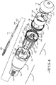
- the circular stapling instrument 100 includes an ergonomic shaft assembly 106, a stapling cartridge assembly 108 having a casing 110, and an anvil assembly 112 detachably connected to a reciprocating anvil adjusting rod 114.
- the stapling reload assembly 102 of the circular stapling instrument includes the stapling cartridge assembly 108 and the anvil assembly 112.
- the circular stapling instrument 100 further includes a handle 116 forming a cavity 118.
- An anvil control member 120 is located on the proximal end of the handle 116 and is operatively coupled with the anvil assembly 112 such that rotation of the anvil control member 120 moves the anvil assembly 112 proximally or distally, depending on the direction of rotation of the anvil control member 120.
- the anvil control member 120 may comprise an anvil closure knob or other type of anvil control member.
- the circular stapling instrument 100 includes a firing trigger 122 which is rotatable in direction 124 from the open position shown to a closed position in which the staples 104 (see FIGS. 7 and 31 ) are injected into tissue (see FIG. 31 ) and excess tissue is cut with an annular blade 126 (see FIG. 31 ) of the stapling reload assembly 102.
- a safety latch 128 is located on the firing trigger 122 and is shown in an up and engaged position which prevents operation of the firing trigger 122.
- the shaft assembly 106 extends distally from the handle 116 and detachably couples with the handle 116 at a proximal end using a connecting nut 130 that attaches to a threaded portion 132 (see FIG. 3 ) of handle 116.
- Opposed attachment members 134 (see FIG. 4 ) of the casing 110 detachably couple to receiving members 136 (see FIG. 3 ) at a distal end of the shaft assembly 106.
- the attachment members 134 comprise deflectable snap members and the receiving members 136 comprise apertures. In other examples, the attachment members 134 and the receiving members 136 may comprise any type of mating members.
- the casing 110 has an exterior surface 138 having a flared driver portion 140 and an outer tubular driver portion 142. Passageways 144 comprise a casing surface aperture extending from the flared driver portion 140 to the outer tubular driver portion 142.
- An annular staple holder 148 (see FIGS. 4-5 , 7 , and 31 ) is attached within a distal end of the casing 110 with attachment members 150 (see FIGS. 4 , 7 , and 31 ) of the staple holder 148 detachably connected to receiving members 152 (see FIGS. 4 , 7 , and 31 ) of the casing 110.
- the attachment members 150 comprise snap projections and the receiving members 152 comprise deflectable snaps, but instead, the attachment members 150 and the receiving members 152 may each comprise any type of connectable members.
- the annular staple holder 148 includes an annular array of staple slots 154 (see FIGS. 4 , 7 , and 31 ) for holding and emitting the staples 104 (see FIG. 31 ).
- a staple driver 156 slidably connects to the annular staple holder 148 with keys 158 (see FIG. 4 ) of the staple driver 156 providing an arrangement that is a detachable connection to keyways 160 (see FIG. 4 ) of the annular staple holder 148.
- the staple driver 156 movably mounts within the casing 110 with alignment slots 162 of an annular exterior driver surface 164 of the staple driver 156 moveably connected to alignment splines 166 of an annular interior casing surface 168 of the casing 110 allowing longitudinal movement of the staple driver 156 within the casing 110 while preventing rotation of the staple driver 156 within the casing 110.
- the exterior driver surface 164 of the staple driver 156 has a flared driver portion 170 and an outer tubular driver portion 171.
- the alignment slots 162 and alignment splines 166 are disposed parallel to longitudinal axis 172 and 174 of the staple driver 156 and the casing 110, but instead, the casing 110 and staple driver 156 may be aligned relative to one another using any number, type, or configuration of alignment members which allow longitudinal movement.
- the staple driver 156 has a plurality of fingers 176 that are received within the staple slots 154 within the staple holder 148.
- the fingers 176 are for engaging and driving a plurality of the staples 104 (see FIG. 31 ) from the staple slots 154 of the staple holder 148 as the staple driver 156 is moved from a pre-fired position (see FIG. 7 ) to a fired position (see FIG. 31 ) by actuation of the firing trigger 122 (see FIG. 3 ).
- flexible detent members 178 of the staple driver 156 are detachably connected to detent bumps 180 of the casing 110.
- This arrangement allows longitudinal movement of the staple driver 156 only when a predetermined amount of force is exerted by a firing bar 282 (see FIGS. 44 - 46 ) on the staple driver 156.
- the deflectable detent members 178 on the staple driver 156 bend inwards thereby disengaging from the detent bumps 180 on the casing 110 allowing the staple driver 156 to move longitudinally and distally.
- the flexible detent member 178 and the detent bumps 180 may comprise other types of mating members.
- the annular blade 126 is mounted within the distal end of the staple driver 156 and is attached by a plurality of blade mounting pins 182 (see FIGS. 5 and 31 ) that project through a like number of mounting holes 184 within a base 186 of the annular blade 126.
- the annular blade 126 has a blade opening 188 (see FIGS. 5 and 31 ) within the base 186.
- the open distal end 190 (see FIGS. 4 , 29 , and 31 ) of the annular blade 126 has a cutting edge 192.
- the annular blade 126 moves with the staple driver 156 when the staple driver 156 is moved distally from the pre-fired position of FIG. 7 to the fired position of FIG. 31 using the firing trigger 122 (see FIG. 3 ).
- the firing trigger 122 When the firing trigger 122 is fired, the firing trigger 122 rotates in direction 124 from its position of FIGS. 38-43 to its position of FIGS. 44-46 forcing a mated firing bar 282 within the casing 110 to move in direction 392 abutting against and forcing the staple striver 156 to also move within the casing 110 in direction 392.
- This movement fires the staple driver 156, and its attached annular blade 126, from its pre-fired position of FIG. 7 and 38-43 to its fired position of FIG. 31 and 44-46 .
- the fingers 176 of the staple driver 156 fire the staples 104 from their pre-fired position in the staple holder 148 shown in FIG. 7 to their fired position out of the staple holder 148 shown in FIG. 31 .
- the reciprocating anvil adjusting rod 114 (see FIGS. 4 and 6 ) is located within the stapling cartridge assembly 108 and is positioned to extend through and move within an annular interior shaft 194 (see FIGS. 4 and 6 ) of the staple driver 156.
- the cross-section of the reciprocating anvil adjusting rod 114 varies in shape and size with one portion along cross-sectional line 3A-3A being of circular shape and having a diameter 401 as shown in FIG. 3A , and another portion along cross-sectional line 3B-3B having parallel sidewalls spaced apart by a distance 402, smaller than diameter 401, as shown in FIG. 3B .
- FIG. 3A and 3A the cross-section of the reciprocating anvil adjusting rod 114 varies in shape and size with one portion along cross-sectional line 3A-3A being of circular shape and having a diameter 401 as shown in FIG. 3A , and another portion along cross-sectional line 3B-3B having parallel sidewalls spaced apart by a distance 402,
- the annular interior shaft 194 extends longitudinally within the staple driver 156 parallel to the longitudinal axis 172 of the staple driver 156.
- a hole 196 extends within the annular interior shaft 194.
- An anvil alignment surface 198 extends longitudinally along an annular interior surface 200 of the annular interior shaft 194. As shown, the anvil alignment surface 198 comprises at least one longitudinal slot, but in alternative configurations, the anvil alignment surface 198 may comprise any number or type of alignment surfaces in various configurations.
- An exterior surface 204 of the annular interior shaft 194 is spaced apart from another annular interior surface 206 of the staple driver 156 with an annular hole 208 extending between the exterior surface 204 of the annular interior shaft 194 and the annular interior surface 206.
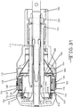
- the anvil assembly 112 comprises an anvil 210, a staple forming surface 212, an annular breakaway washer 214, and a metal shaft 216.
- the anvil 210 is a one-piece polymeric molded part comprising an anvil shaft 218 integrally molded to an anvil base surface 220.
- the anvil 210 can, for example, be made of a polymer comprising glass filled or carbon filled Nylon, but it may also be made of similar composite materials having a tensile strength greater than 15,000 psi in order to prevent excessive bending under tissue forces.
- the aforementioned glass filled or carbon filled nylon polymer may have a tensile strength greater than 15,000 psi.
- the anvil base surface 220 is molded to the staple forming surface 212 and metal shaft 216, but the anvil base surface 220 may instead or in addition be attached to the staple forming surface 212 using various attachment mechanisms.
- the staple forming surface 212 is made of sheet metal or a plate comprising stainless steel, is annular in shape, and includes staple forming pockets.
- the staple forming surface 212 may instead be made of aluminium or other materials that can withstand staple forming forces.
- the annular breakaway washer 214 is press-fit within a cavity 222 of the anvil base surface 220 adjacent to the anvil base surface 220, but the annular breakaway washer 214 may instead be attached within the cavity 222 of the anvil base surface 220 using other attachment mechanisms.
- the annular breakaway washer 214 may be made of a plastic comprising ABS (Acrylonotrile-Butadiene-Styrene), or it may be made of Nylon, Polyethylene or Polypropylene.
- the anvil shaft 218 is molded around an exterior surface 224 of an end 226 of the metal shaft 216, with the metal shaft 216 extending into a molded hole 228 of the anvil shaft 218.
- the molded hole 228 of the anvil shaft 218 ends within the anvil shaft 218 and does not extend through the distal end of the anvil base surface 220.
- An interior surface 230 of the anvil shaft 218 comprises receiving members 232 which are molded to attachment members 234 of the exterior surface 224 of the end 226 of the metal shaft 216.
- the receiving members 232 comprise molded annular ribs ( Fig 38 )
- the attachment members 234 comprise annular grooves ( Fig 8 ).
- the receiving members 232 and attachment members 234 may comprise grooves and threads, female and male members, or other types of attachment mechanisms, or the anvil shaft 218 may be attached to the metal shaft 216 using other attachment mechanisms.
- a proximal end channel 236 extends through the metal shaft 216. End 238 of the metal shaft 216 includes expansion slots 240 (see FIG. 2 ).
- the metal shaft 216 may be made of a stainless steel or other material.
- the metal shaft 216 and the staple forming surface 212 may be pre-manufactured.
- the pre-manufactured metal shaft 216 and the pre-manufactured staple forming surface 212 are then inserted into an injection mold.
- the mold is then used to form the anvil 210 within the mold causing the anvil 210 to be molded to both the pre-manufactured metal shaft 216 and to the pre-manufactured staple forming surface 212.
- the anvil base surface 220 forms and is molded to the pre-manufactured staple forming surface 212, while the anvil shaft 218 forms and is molded around the end 226 of the pre-machined metal shaft 216.
- the annular breakaway washer 214 is then press-fit within the cavity 222 of the molded anvil base surface 220.
- Other manufacturing processes may, however, be used.
- the engagement member 244 (see FIGS. 2 and 6 ) of the reciprocating anvil adjusting rod 114 detachably couples within the proximal end channel 236 of the metal shaft 216 using a snap-fit coupling.
- This arrangement operatively couples the metal shaft 216 and the attached anvil 210 to the anvil control member 120 of the reciprocating anvil adjusting rod 114, but the engagement member 244 of the reciprocating anvil adjusting rod 114 may be attached to the metal shaft 216 using other attachment mechanisms.
- the expansion slots 240 allow end 238 of the metal shaft 216 to expand during the coupling to the engagement member 244 of the reciprocating anvil adjusting rod 114.
- the anvil shaft 218 includes an alignment surface 246 formed at the time of molding the anvil 210.
- the alignment surface 246 comprises at least one spline disposed parallel to a longitudinal axis 248 of the anvil shaft 218.
- the alignment surface 246 extends from a top portion 250 of the anvil shaft 218, along an exterior annular surface 252 of the anvil shaft 218, to a bottom portion 254 of the anvil shaft 218.
- the metal shaft 216 of the anvil assembly 112 does not contain an alignment surface.
- the alignment surface 246 may be as shown or may comprise any number or type of alignment surfaces in varying configurations. For instance, as shown in FIG.
- the alignment surface 246 may extend from a top portion 250 of the anvil shaft 218, along the exterior annular surface 252 of the anvil shaft 218, and stop at a middle portion 256 of the anvil shaft 218 without extending to the bottom portion 254 of the anvil shaft 218.
- the anvil assembly 112 is movable from an open position (see FIG. 6 ) in which the staple forming surface 212 is disposed away from the casing 110 for the reception of tissue, to a closed position (see FIG. 7 ) in which the staple forming surface 212 is disposed adjacent to the casing 110 of the stapling cartridge assembly 108 clamping tissue between the staple holder 148 and the staple forming surface 212 prior to firing the staple driver 156 to staple and cut the clamped tissue. This is due to the tip 242 (see FIGS.
- the engagement member 244 of the reciprocating anvil adjusting rod 114 extending within the annular interior shaft 194 of the staple driver 156 and being connected within the channel 236 of proximal end 238 of the metal shaft 216 of the anvil assembly 112.
- the anvil shaft 218, which is connected to the metal shaft 216 is moveably disposed within the annular interior shaft 194 of the staple driver 156 allowing movement of the staple forming surface 212 of the anvil assembly 112 relative to the staple driver 156 and casing 110.
- the alignment surface 246 (see FIG. 8 ) of the anvil shaft 218 is configured to mate with the anvil alignment surface 198 (see FIG. 4 ) of the staple driver 156 to rotationally align the staple forming surface 212 with the staple holder 148 when the anvil base surface 220 is in the closed position (see FIG. 7 ) adjacent to the stapling cartridge assembly 108.
- the alignment surface 246 see FIG. 8
- the alignment surface 246 of the anvil shaft 218 reaches the annular interior shaft 194 of the staple driver 156, the alignment surface 246 will mate with the anvil alignment surface 198 of the annular interior shaft 194 rotationally aligning the staple forming surface 212 with the staple holder 148 as the anvil base surface 220 moves into the closed position adjacent to the stapling cartridge assembly 108.
- the markings 120A adjacent the anvil control member 120 visually indicate the gap distance between the staple forming surface 212 of the anvil 112 (see FIG. 7 ) and the staple guide 148 (see FIG. 7 ) providing feedback to the user on the compressed tissue thickness.
- the proximal end of the reciprocating anvil adjusting rod 114 pops through the hole 120F in the anvil control member 120.
- the staple driver 156 drives the annular blade 126 into the compressed tissue captured between the staple forming surface 212 on the anvil 210 and the surface of the staple guide 148, thereby cutting the tissue against the breakaway washer 214 of the anvil assembly 112.
- FIG. 9 illustrates a flowchart 258 showing one example of a method of aligning a stapling reload assembly of a circular stapling instrument, such as the instrument that has just been described and any of its variations.
- a stapling reload assembly of a circular stapling instrument is provided.
- the provided circular stapling instrument includes a casing, a staple holder attached to the casing, a staple driver, an annular blade, and an anvil.
- the staple driver is movably mounted within the casing in an aligned configuration, and attachment members of the staple driver are connected to receiving members of the casing preventing the staple driver from moving past a certain point within the casing until a predetermined amount of force is applied on the staple driver by a firing bar.
- an anvil base surface of the anvil is moved from an open position away from the casing, in which a staple forming surface of the anvil is not rotationally aligned with the staple holder attached to the casing, towards a closed position adjacent to the casing.
- an alignment surface of the anvil is mated with an anvil alignment surface of the staple driver to rotationally align the staple forming surface of the anvil with the staple holder when the anvil base surface is in the closed position adjacent to the casing.
- the alignment surface of the anvil may comprise at least one spline, and the anvil alignment surface of the staple driver may comprise at least one slot, although the number, type, and configuration of the alignment surface of the anvil and the anvil alignment surface of the driver may vary.
- the present invention may provide proper alignment directly between the anvil and the staple driver instead of requiring a first alignment between the anvil and the casing, and a second alignment between the staple driver and the casing as is done in current devices.
- This method of directly aligning the driver and the anvil reduces the potential of alignment variation and results in improved staple form.
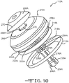
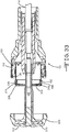
- FIG. 10 illustrates an exploded view of another example of an anvil assembly 112A that can be used with the circular staplers previously described.
- the anvil assembly 112A comprises an anvil 210A, a staple forming surface 212A, an annular breakaway washer 214A, and a metal shaft 216A.
- the anvil 210A is a one-piece, polymer, molded part comprising an anvil shaft 218A molded to an anvil base surface 220A.
- the anvil 210A may be made of a polymer comprising glass filled or carbon filled Nylon, or it may be made of similar composite materials having a tensile strength greater than 15,000 psi in order to prevent excessive bending under tissue forces.
- the glass filled or carbon filled Nylon polymer may have a tensile strength greater than 15,000 psi.
- the metal shaft 216A extends through a molded hole 228A which extends through both the anvil shaft 218A and the anvil base surface 220A.
- One end 226A of the metal shaft 216A extends out of the molded hole 228A and abuts against a top portion 268 of the anvil base surface 220A.
- End 226A of the metal shaft 216A has a larger diameter 270 than the diameter 272 of the molded hole 228A.
- the other end 238A of the metal shaft 216A extends out of the molded hole 228A of the anvil shaft 218A.
- the metal shaft 216A comprises attachment members (hidden from sight) which attach to receiving members (hidden from sight) of the anvil shaft 218A.
- the attachment members comprise threads and the receiving members comprise grooves, but the attachment members and receiving members may instead comprise male and female members, or other types of attachment mechanisms.
- the metal shaft 216A may be attached to the anvil shaft 218A using other attachment mechanisms.
- a channel 236A extends within proximal end 238A of the metal shaft 216A.
- End 238A of the metal shaft 216A also includes expansion slots 240A.
- the metal shaft 216A is made of a metal comprising heat-treated stainless steel, but it may instead be made of other steels or other suitable materials.
- the anvil base surface 220A is molded to the staple forming surface 212A, but the anvil base surface 220A may instead be attached to the staple forming surface 212A using other attachment mechanisms.
- the staple forming surface 212A is made of a sheet metal comprising austenitic stainless steel, is annular in shape, and includes staple forming pockets, but the staple forming surface 212A may instead be made of other metals, stainless steels, Aluminum, sheet, or plate.
- annular breakaway washer 214A is press-fit within a cavity 222A of the anvil base surface 220A adjacent to the anvil base surface 220A, the annular breakaway washer 214A may instead be attached within the cavity 222A of the anvil base surface 220A using other attachment mechanisms.
- the annular breakaway washer 214A is made of a plastic comprising ABS (Acrylonotrile-Butadiene-Styrene), but it could be made of Nylon, Polyethylene, or Polypropylene or other suitable materials.
- the staple forming surface 212A is pre-manufactured.
- the pre-manufactured staple forming surface 212A is then inserted into an injection mold.
- the mold is then used to form the anvil 210A within the mold causing the anvil 210A to be molded to the staple forming surface 212A.
- the anvil base surface 220A forms and is molded to the staple forming surface 212A.
- the annular breakaway washer 214A is then press-fit within the cavity 222A of the molded anvil base surface 220A.
- end 238A of a pre-manufactured metal shaft 216A is extended into the molded hole 228A in the anvil base surface 220A and out of the molded hole 228A in the anvil shaft 218A so that end 226A of the metal shaft 216A abuts against the top portion 268 of the anvil base surface 220A.
- This step can be performed by the user prior to use.
- the metal shaft 216A is detachably connected to the anvil shaft 218A due to the attachment members (hidden from view) of the metal shaft 216A mating with the receiving members (hidden from view) of the anvil shaft 218A as end 238A of the pre-manufactured metal shaft 216A is extended into and out of the molded hole 228A in the anvil 210A.
- This is one manufacturing process, but other manufacturing processes may be used.
- the engagement member 244 of the reciprocating anvil adjusting rod 114 detachably couples within the proximal end channel 236A of the metal shaft 216A using a snap-fit coupling operatively coupling the metal shaft 216A and the attached anvil 210A to the anvil control member 120 through the reciprocating anvil adjusting rod 114, but the engagement member 244 of the reciprocating anvil adjusting rod 114 may be attached to the metal shaft 216A using other attachment mechanisms.
- the expansion slots 240A allow end 238A of the metal shaft 216A to expand during the coupling to the engagement member 244 of the reciprocating anvil adjusting rod 114.
- the metal shaft 216A may be removed from the anvil 210A by detaching the attachment members (hidden from sight) of the metal shaft 216A from the receiving members (hidden from sight) of the anvil shaft 218A, the anvil 210A may be disposed of, the metal shaft 216A may be sterilized, and the metal shaft 216A may be attached to a new anvil using the same above-described process to allow the metal shaft 216A to be reused on another patient in combination with the new anvil and new stapling cartridge assembly.
- the anvil shaft 210A includes an alignment surface 246A formed at the time of molding the anvil 210A due to the mold.
- the alignment surface 246A comprises at least one spline disposed parallel to a longitudinal axis 248A of the anvil shaft 218A.
- the alignment surface 246A extends from a top portion 250A of the anvil shaft 218A, along an exterior annular surface 252A of the anvil shaft 218A, to a bottom portion 254A of the anvil shaft 218A.
- the metal shaft 216A of the anvil assembly 112A does not contain an alignment surface.
- the alignment surface 246A may comprise any number or type of alignment surfaces in varying configurations.
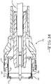
- FIG. 12 illustrates an exploded view of an alternative anvil assembly 112B comprising an anvil 210B, a staple forming surface 212B, and an annular breakaway washer 214B.
- the anvil 210B is a one-piece, polymer, molded part comprising an anvil shaft 218B molded to an anvil base surface 220B.
- the anvil 210B is made of a polymer comprising glass filled or carbon filled Nylon, but the anvil 210B may be made of similar composite materials having a tensile strength greater than 15,000 psi in order to prevent excessive bending under tissue forces.
- the glass filled or carbon filled Nylon polymner may have a tensile strength greater than 15,000 psi.
- a proximal end channel 236B extends within the anvil shaft 218B.
- Anvil shaft 218B includes expansion slots 240B.
- the anvil base surface 220B is molded to the staple forming surface 212B, but the anvil base surface 220B may instead be attached to the staple forming surface 212B using varying attachment mechanisms.
- the staple forming surface 212B is made of a metal comprising austenitic stainless steel, is annular in shape, and includes staple forming pockets. Alternatively, the staple forming surface 212B may be made of other metals, stainless steels, Aluminum, sheet, or plate.
- the annular breakaway washer 214B is press-fit within a cavity 222B of the anvil base surface 220B adjacent to the anvil base surface 220B, but the annular breakaway washer 214B may instead be attached within the cavity 222B of the anvil base surface 220B using varying attachment mechanisms.
- the annular breakaway washer 214B is made of a plastic comprising ABS (Acrylonotrile-Butadiene- Styrene), but the annular breakaway washer 214B may instead be made of other materials.
- the staple forming surface 212B is pre-manufactured.
- the pre-manufactured staple forming surface 212B is then inserted into an injection mold.
- the mold is then used to form the anvil 210B within the mold causing the anvil 210B to be molded to the staple forming surface 212B.
- the anvil base surface 220B forms and is molded to the staple forming surface 212B.
- the anvil shaft 218B, including the anvil rod attachment portion is integrally molded to the anvil base surface 220B.
- the annular breakaway washer 214B is then press-fit within the cavity 222B of the molded anvil base surface 220B.
- Other manufacturing processes may be used.
- the engagement member 244 of the reciprocating anvil adjusting rod 114 detachably couples within the proximal end channel 236B of the anvil shaft 218B using a snap-fit coupling operatively coupling the anvil shaft 218B of the anvil 210B to the anvil control member 120 through the reciprocating anvil adjusting rod 114, but the engagement member 244 of the reciprocating anvil adjusting rod 114 may instead be attached to the anvil shaft 218B using other attachment mechanisms.
- the expansion slots 240B allow the anvil shaft 218B to expand during the coupling to the engagement member 244 of the reciprocating anvil adjusting rod 114.
- the anvil shaft 218B includes an alignment surface 246B formed at the time of molding the anvil 210B.
- the alignment surface 246B comprises at least one spline disposed parallel to a longitudinal axis 248B of the anvil shaft 218B.
- the alignment surface 246B extends from a top portion 250B of the anvil shaft 218B, along an exterior annular surface 252B of the anvil shaft 218B, and stops at a middle portion 256B of the anvil shaft 218A without extending to the bottom portion 254B of the anvil shaft 218A.
- the alignment surface 246B may comprise any number or type of alignment surfaces in varying configurations.
- FIG. 14 illustrates a flowchart 274 showing a method of manufacturing an anvil assembly such as that of FIG. 12 .
- a pre-manufactured staple-forming surface which may be made of metal or other material, is disposed within a mold.
- the anvil assembly is formed by molding an anvil to the pre-manufactured staple-forming surface within the mold, with the anvil molded to have an anvil shaft extending from an anvil base surface.
- the anvil may be molded to be one-piece from a polymer such as glass filled or carbon filled Nylon as above, but also as above the anvil may be molded out of other materials.
- Step 278 may further include molding the anvil shaft to have at least one alignment surface comprising an alignment spline or another type of alignment surface.
- Step 278 may further include molding the anvil assembly so that the anvil shaft is molded to a pre-manufactured shaft, which may be made of metal or other materials, disposed within the mold during step 276.
- a pre-manufactured shaft which may be made of metal or other materials, may be attached to the anvil shaft of the molded anvil assembly after the anvil is molded.
- a breakaway washer is attached, using press-fitting or other attachment mechanisms, to the anvil base surface of the molded anvil assembly.
- the breakaway washer may be annular or in another shape, may be made of a plastic comprising ABS (Acrylonotrile-Butadiene-Styrene), or may be made of other types of materials. A method in which one or more steps as set out above differs may also be used.
- One or more examples of the present invention may reduce one or more problems associated with previous anvil assemblies.
- the invention may provide an anvil assembly which may be manufactured at one-third the cost of current anvil assemblies.
- the circular stapling instrument 100 includes handle 116, reciprocating anvil adjusting rod 114, firing bar 282, carrier cover 284, shaft assembly 106 detachably coupled with the handle 116, stapling cartridge assembly 108, and anvil assembly 112 which is detachably coupled with the reciprocating anvil adjusting rod 114.
- the handle 116 forms a cavity 118 which receives the firing bar 282 and the reciprocating anvil adjusting rod 114.
- the reciprocating anvil adjusting rod 114 has an engagement member 244 at a tip 242 of the reciprocating anvil adjusting rod 114 and a threaded adjustment member 286 which is detachably coupled with the anvil control member 120 at a proximal end of the reciprocating anvil adjusting rod 114.
- the firing bar 282 is used to stabilize and secure the reciprocating anvil adjusting rod 114 within the handle 116.
- Firing bar 282 forms a pair of engagement grooves 288 and 290 and has an engagement shaft 292 at a distal end of the firing bar 282.
- Engagement grooves 288 and 290 are preferably formed on opposing sides of firing bar 282.
- Firing trigger 122 includes an upper end 294 which engages the engagement grooves 288 and 290 and detachably secures the firing bar 282 and the reciprocating anvil adjusting rod 114 within the cavity 118 of the handle 116.
- engagement grooves 288 and 290 may be replaced with any detachable coupling, as described herein.
- portions of the upper end 294 of the firing trigger 122 each extend into one of the engagement grooves 288 and 290, detachably securing both the firing bar 282 and the reciprocating anvil adjusting rod 114 in the cavity 118.
- the engagement grooves 288 and 290 and the upper end 294 of the firing trigger 122 allow for both the firing bar 282 and the reciprocating anvil adjusting rod 114 to be easily placed into and removed from the cavity 118 allowing them to be easily serviced or replaced.
- the design of the cavity 118 and the features of components described above are such that they allow clear visualization by the user as they are placed in the correct location and orientation. This arrangement also prevents the user from incorrectly assembling the device.
- the engagement shaft 292 forms an opening 296 through which the tip 242 and the engagement member 244 of the reciprocating anvil adjusting rod 114 are received. Receiving the reciprocating anvil adjusting rod 114 through the opening 296 of the engagement shaft 292 helps to center the reciprocating anvil adjusting rod 114 within the handle 116 and align the reciprocating anvil adjusting rod 114 within the stapling cartridge assembly 108.
- the stapling cartridge assembly 108 (see FIGS. 1 and 2 ) detachably couples with a distal end of the shaft assembly 106 (see FIG. 3 ).
- the tip 242 of the engagement member 244 of the reciprocating anvil adjusting rod 114 extends within and through the casing 110 (see FIG. 2 ) and detachably couples to the proximal end channel 236 (see FIG. 2 ) of the metal shaft 216 of the anvil assembly 112 using a snap-fit coupling.
- carrier cover 284 slides over the handle 116 and covers the firing bar 282 and a portion of the reciprocating anvil adjusting rod 114 within cavity 118.
- carrier cover 284 forms an opening 298 through which a threaded portion 132 of the handle 116 is received.
- the opening 298 is preferably U-shaped and formed on an underside 300 of the carrier cover 284, so that when the carrier cover 284 is slid over the handle 116, an abutment portion 302 of the carrier cover 284 is pressed against a portion of the handle 116, indicating that the carrier cover 284 is properly positioned over the firing bar 282 and a portion of the reciprocating anvil adjusting rod 114 within the cavity 118.
- carrier cover 284 protects both the firing bar 282 and the reciprocating anvil adjusting rod 114 within the cavity 118 and allows for them to be easily serviced or replaced.
- Shaft assembly 106 is detachably coupled with the handle 116 at a proximal end and detachably coupled with the stapling cartridge assembly 108 (see FIG. 1 ) at a distal end.
- detachable refers to a first component or member which is designed to be unfastened or disconnected without damage to another component or member.
- detachably coupled or detachably secured refers to coupling or securing a first member to a second member in a manner in which the two members are designed to be unfastened or disconnected from each other without damage to either member. This allows for a user to disconnect or unfasten the two members from each other without damage so that a user may service the two members.
- Detachable couplings may include a snap-fit coupling, a frictionally engaging coupling which includes members which frictionally engage each other, a threaded coupling, a magnetic coupling, or a mechanical coupling such as a hook and loop type fastener.
- the shaft assembly 106 has the connecting nut 130 with internal threads 304 which are detachably coupled with the threaded portion 132 on the handle 116.
- connecting nut 130 may be replaced with any detachable coupling, as described herein.
- the anvil control member 120 is detachably coupled with the reciprocating anvil adjusting rod 114.
- the anvil control member 120 is detachably coupled with the threaded adjustment member 286 at a proximal end of the reciprocating anvil adjusting rod 114 by turning the anvil control member 120 on the threaded adjustment member 286.
- turning the anvil control member counter-clockwise 120 opens the device and turning clockwise closes the device.
- a portion of the anvil control member 120 and a portion of the reciprocating anvil adjusting rod 114 are detachably secured within the cavity 118 of the handle 116.
- the cavity 118 forms an indentation 306 which mates with a portion of the anvil control member 120, in order to detachably secure the anvil control member 120 and the reciprocating anvil adjusting rod 114 within the cavity 118.
- the indentation and protrusion relationship can be reversed.
- the tip 242 and the engagement member 244 of the reciprocating anvil adjusting rod 114 are received through the opening 296 of the engagement shaft 292 of the firing bar 282 and then the engagement grooves 288, 290 of the firing bar 282 are placed over and then around the upper end 294 of the firing trigger 122, detachably securing the firing bar 282, the reciprocating anvil adjusting rod 114, and the anvil control member 120 within the cavity 118.
- the carrier cover 284 is then slid over the handle 116 and covers the firing bar 282 and a portion of the reciprocating anvil adjusting rod 114 within cavity 118.
- the threaded portion 132 of the handle 116 is received through the opening 298 in the carrier cover 284, and the carrier cover 284 is slid until abutment portion 302 of the carrier cover 284 is pressed against a portion 132a of the handle 116, indicating that the carrier cover 284 is properly positioned.
- the reciprocating anvil adjusting rod 114 is placed through and within the shaft assembly 106 and the shaft assembly 106 is detachably coupled with the handle 116.
- shaft assembly 106 has the connecting nut 130 with the internal threads 304 which are detachably coupled with the threaded portion 132 on the handle 116.
- the shaft assembly 106 detachably secures the carrier cover 284 to the handle 116.
- stapling cartridge assembly 108 is detachably coupled to the shaft assembly 106, and the tip 242 of the reciprocating anvil adjusting rod 114 extends through a central shaft formed in the stapling cartridge assembly 108.
- anvil assembly 112 is detachably coupled with the reciprocating anvil adjusting rod 114 via the engagement member 244 of the reciprocating anvil adjusting rod 114 and the proximal end channel 236 of the metal shaft 216 of the anvil assembly 112.
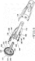
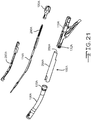
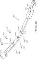
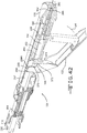
- a curved circular stapling instrument 100A which includes a stapling cartridge assembly 108A having a casing 110A, an anvil assembly 112C attached to a curved reciprocating anvil adjusting rod 114A of an anvil opening mechanism, as discussed above, to prevent accidental removal of the anvil assembly 112C, a curved firing bar 282A which is detachably coupled with the flexible reciprocating anvil adjusting rod 114A, a carrier cover 284A detachably coupled with a handle 116A, a control member 120A detachably coupled with the curved reciprocating anvil adjusting rod 114A via a threaded adjustment member 286A, and an ergonomic curved shaft assembly 106A having a connecting nut 130A detachably coupled with the handle 116A via threaded portion 132A.
- Curved circular stapling instrument 100A includes curved components, such as the flexible reciprocating anvil adjusting rod 114A, the curved firing bar 282A, and the curved shaft assembly 106A, to aid in insertion into a body cavity of a mammal.
- each other circular stapling instrument 100 or curved circular stapling instrument 100A provide a reusable stapling instrument having an open architecture which uses a carrier cover 284, 284A having a u-shaped opening 298, 298A that allows for additional components, such as reciprocating anvil adjusting rod 114, 114A and shaft assembly 106, 106A, to be assembled in a primarily transverse direction.
- a transverse assembly allows for easy visualization for assembly and decreases assembly time, improves ease of assembly, and disassembly. As a result, the amount of time required to assemble the circular stapling instrument 100 or the curved circular stapling instrument 100A having the open assembly architecture is often less than one minute.
- the open architecture allows for presence of features that communicate where the components need to be placed. Further, by providing components which are detachably coupled with each other, the circular stapling instrument 100 or 100A is easily assembled or disassembled, allowing for cleaning and sterilization of the circular stapling instrument 100 or 100A after use.
- a circular stapling instrument 100D which includes a stapling cartridge assembly 108D having a casing 110D, an anvil assembly 112D attached to a reciprocating anvil adjusting rod 114D of an anvil opening mechanism, as discussed above, to prevent accidental removal of the anvil assembly 112D, a firing bar 282D which is detachably coupled with the reciprocating anvil adjusting rod 114D, a carrier cover 284D coupled with a handle 116D, a control member 120D coupled with the reciprocating anvil adjusting rod 114D, and a shaft assembly 106D having a connecting nut 130D coupled with the handle 116D via a threaded portion 132D.
- the circular stapling instrument 100D is a curved circular stapling instrument, as seen with instrument 100D, and includes curved components, such as a curved reciprocating anvil adjusting rod 114D, a curved firing bar 282D, and an ergonomic curved shaft assembly 106D, to aid in insertion into a body cavity of a mammal.
- curved components such as a curved reciprocating anvil adjusting rod 114D, a curved firing bar 282D, and an ergonomic curved shaft assembly 106D, to aid in insertion into a body cavity of a mammal.
- circular stapling instrument 100D need not be a curved circular stapling instrument, as seen with circular stapling instrument 100D, and may be any type of circular stapling instrument, such as a relatively straight circular stapling instrument, as seen with circular stapling instrument 100, and have relatively straight components, such as a relatively straight reciprocating anvil adjusting rod 114D, a relatively straight firing bar 282D, and a relatively straight shaft assembly 106D.
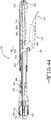
- the reciprocating anvil adjusting rod 114D includes a first engagement member 244D at a tip 242D of the reciprocating anvil adjusting rod 114D and a threaded adjustment member 286D at a base 402D of the reciprocating anvil adjusting rod 114D.
- the reciprocating anvil adjusting rod 114D includes a base 402D at one end, an engagement member 244D at an opposing end, and a flexible tension band 400D, which may be flexible and curved, connecting the base 402D with the engagement member 244D.
- the firing bar 282D is movably connected at a first end 430D with a firing trigger 122D and movably connected at a second end 432D with a stapling cartridge assembly 108D through a second engagement member 416D.
- the firing bar 282D forms a first engagement surface 406D which faces a respective second engagement surface 408D formed on the reciprocating anvil adjusting rod 114D.
- the tension band 400D forms the second engagement surface 408D which faces the first engagement surface 406D on the firing bar 282D.
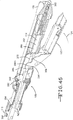
- Circular stapling instrument 100D further includes a frictional reducing member 420D located in between the first and second engagement surfaces 406D, 408D in order to reduce friction between the reciprocating anvil adjusting rod 114D and the firing bar 282D. Movement between the reciprocating anvil adjusting rod 114D and the firing bar 282D occurs when the firing trigger 122D is engaged by the handle 116D and fired, causing the firing bar 282D to move towards and engage the stapling cartridge assembly 108D and fire staples from the stapling cartridge assembly 108D.
- Movement between the reciprocating anvil adjusting rod 114D and the firing bar 282D also occurs when the control member 120D is activated causing the reciprocating anvil adjusting rod 114D, and the anvil assembly 112D connected to the tip 242D of the reciprocating anvil adjusting rod 114D, to move towards or away from the stapling cartridge assembly 108D in order to adjust a distance between the stapling cartridge assembly 108D and the anvil assembly 112D.
- Either movement between the reciprocating anvil adjusting rod 114D and the firing bar 282D causes the reciprocating anvil adjusting rod 114D to slidably engage the firing bar 282D, and results in friction between the reciprocating anvil adjusting rod 114D and the firing bar 282D.
- Friction between the reciprocating anvil adjusting rod 114D and the firing bar 282D in curved circular stapling instrument 100D typically could be 20-40% higher over a relatively straight circular stapling instrument 100.
- the configuration of the circular stapling instrument 100D may cause the tension band 400D to exert a contact force on the firing bar 282D, increasing friction between the firing bar 282D and the reciprocating anvil adjusting rod 114D.
- frictional reducing member 420D in between the first and second engagement surfaces 406D, 408D, friction between the reciprocating anvil adjusting rod 114D and the firing bar 282D may be reduced.
- Frictional reducing member 420D may be any mechanical device or chemical compound which may be used to reduce friction between two members, such as between the reciprocating anvil adjusting rod 114D and the firing bar 282D.
- the frictional reducing member 420D provides a reduced coefficient of friction ⁇ reduced between two members which is less than a normal coefficient of friction ⁇ normal present between the two members, when the two members are without the frictional reducing member.
- the frictional reducing member 420D provides for a reduced coefficient of friction ⁇ reduced which is at least 20% less than, and more preferably, at least 40% less than the normal coefficient of friction ⁇ normal present between the two members.
- Chemical compounds for frictional reducing member 420D may include: solid coatings including graphite or polymer coatings such as Teflon. Chemical compounds for frictional reducing member 420D may be applied as coatings which bond to either or both the first and second engagement surfaces 406D, 408D. Chemical compounds for frictional reducing member 420D may be also be applied as coatings to free moving intermediate components captured between the two engagement surfaces 406D, 408D.
- Mechanical devices used for frictional reducing member 420D include any mechanical device which can reduce friction between a pair of surfaces, such as a ball bearing or a roller bearing. Frictional reducing member 420D may be connected with either or both the reciprocating anvil adjusting rod 114D and the firing bar 282D. The frictional reducing member 402D is designed so that it does not wipe-out or degrade during cleaning and servicing the handle for reuse.
- the frictional reducing member 420D includes a roller 404D which is connected with the firing bar 282D using a pin 412D and which is disposed within a cavity 410D formed in the firing bar 282D.
- the pin 412D is disposed within a hole 414D formed through the firing bar 282D.
- more than one roller 404D is connected with the firing bar 282D, such as three rollers 404D.
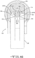
- the hole 414D may form a circular opening through which the pin 412D is disposed, as shown in FIG. 26 , allowing for little movement of the pin 412D.
- the hole 414D may form a generally oval shaped opening through which the pin 412D is disposed and may move laterally within, as shown in FIG. 28 , allowing for more lateral movement of the pin 412D either towards or away from either end 430D, 432D of firing bar 282D than top/bottom movement of pin 412D which is not towards or away from either end 430D, 432D of firing bar 282D, allowing an additional degree of freedom.
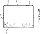
- FIG. 29 illustrates a perspective view of the annular blade 126 of the stapling cartridge assembly 108 of the circular stapling instrument 100 of FIG. 4 .
- the annular blade 126 comprises an annular cutting edge 192 and a breakaway washer attachment member 308.
- the annular blade 126, including the annular cutting edge 192 and the breakaway washer attachment member 308, is made of a metal such as stainless steel, or any other material hard enough to cut.
- the breakaway washer attachment member 308 comprises a plurality of spaced-apart breakaway washer retention barbs extending from locations 310 of the annular blade 126 which are adjacent to the cutting edge 192.
- the breakaway washer attachment member 308 extends inwardly at a non-parallel angle 312 relative to the cutting edge 192.
- the non-parallel angle 312 maybe in a range of 56 to 60 degrees, or the non-parallel angle 312 may be in a range of 30 to 60 degrees.
- the breakaway washer attachment member 308 may vary in material, quantity, shape, size, location, direction, or configuration relative to the annular blade 126.
- the breakaway washer attachment member 308 may comprise a snap, an impression, or other type of attachment member.
- FIG. 6 illustrates the anvil base surface 220 of the anvil assembly 112 of the stapling reload assembly 102 of the circular stapling instrument 100 being in an open position relative to and apart from the casing 110, and the staple driver 156 and the attached annular blade 126 being in a pre-fired position retracted within the casing 110.
- the annular breakaway washer 214 is press-fit within the cavity 222 of the anvil base surface 220 of the anvil 210.
- a protective member 314 is attached, using a hook 316, to a top portion 318 of the annular breakaway washer 214 disposed within the cavity 222 of the anvil base surface 220.
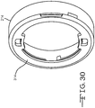
- FIG. 30 shows a close-up view of the annular breakaway washer 214 attached to the protective member 314.
- the protective member 314 comprises an annular protective cap made of a red colored polycarbonate.
- the protective member 314 may vary in material, shape, size, location, color, or configuration, and may be attached to the annular breakaway washer 214 using various attachment mechanisms.
- the protective member 314 may be omitted and the annular breakaway washer 214 may be press-fit within the cavity 222 of the anvil base surface 220 without the protective member 314.
- FIG. 7 shows the anvil base surface 220 of the anvil assembly 112 having been moved to a closed position relative to and adjacent to the casing 110 with the staple driver 156 and the attached annular blade 126 still being in the pre-fired position retracted within the casing 110 spaced apart from the annular breakaway washer 214.
- the flexible detent members 178 of the staple driver 156 are detachably connected to the detent bumps 180 of the casing 110 with the connection preventing the staple driver 156 from moving until a predetermined amount of force is applied.
- the flexible detent members 178 and the detent bumps 180 may comprise various types of mating members.
- FIG. 31 illustrates the staple driver 156 and the attached annular blade 126 having been fired moving the staple driver 156 relative to the casing 110 from the pre-fired position to the fired position in which the cutting edge 192 of the annular blade 126 moves into and cuts the annular breakaway washer 214 while the anvil base surface 220 of the anvil assembly 112 is in the closed position.
- the flexible detent members 178 of the staple driver 156 are released from the detent bumps 180 of the casing 110 allowing the staple driver 156 to move past the certain point 320 relative to the casing 110.
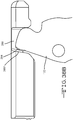
- FIG. 32 illustrates a close-up view of the cutting edge 192 of the annular blade 126 of FIG. 31 cutting the annular breakaway washer 214.
- the cutting edge 192 cuts a web 320, disposed between spaced-apart walls 322 and 324, of the annular breakaway washer 214.
- the breakaway washer attachment member 308 fixedly attaches to one of the spaced-apart walls 322 of the annular breakaway washer 214 locking the annular blade 126 to the annular breakaway washer 214 with the protective member 314 (see FIG. 31 ) still attached to the top portion 318 (see FIG. 31 ) of the annular breakaway washer 214 disposed within the cavity 222 of the anvil base surface 220.
- FIG. 33 illustrates the anvil base surface 220 of the anvil assembly 112 having been moved back into the open position away from the casing 110 after the staple driver 156 and the attached annular blade 126 were fired cutting the annular breakaway washer 214.
- the annular breakaway washer 214 remains locked in place over the annular blade 126, due to the annular breakaway washer attachment member 308, with the protective member 314 still attached to the top portion 318 of the annular breakaway washer 214 acting as a protective barrier over the cutting edge 192 of the annular blade 126.
- the protective member 314 prevents the cutting edge 192 of the annular blade 126 from making an unintended cut after the annular blade 126 has been fired.
- At least one of the annular breakaway washer 214 or the protective member 314 comprises a visual indicator 326 indicating, as a precautionary measure, that the staple driver 156 and the attached annular blade 126 have been fired.
- the visual indicator 326 comprises a first color which is different than a second color of the casing 110 of the circular stapling apparatus 100.
- the visual indicator 326 may comprise any type of visual indicator visually indicating when the staple driver 156 and the attached annular blade 126 have been fired.
- only the inner portion of the cut annular breakaway washer 214 and the visual indicator 326 remain attached to the annular blade 126.
- the outer portion of the cut annular breakaway washer 214 remains attached to the anvil base surface 220 after opening the instrument.
- FIG. 34 shows the anvil 210 of the anvil assembly 112 of FIG. 33 having been removed from the circular stapling instrument 100, after the staple driver 156 and the attached annular blade 126 were fired cutting the annular breakaway washer 214, with the annular breakaway washer 214 and protective member 314 remaining behind attached to the annular blade 126 due to the washer attachment member 308.
- the protective member 314 continues to prevent the cutting edge 192 of the annular blade 126 from making an unintended cut after the staple driver 156 and the attached annular blade 126 have been fired.
- the visual indicator 326 continues to indicate that the staple driver 156 and the attached annular blade 126 have been fired.
- FIG. 35 illustrates a new anvil 210C having attempted to be attached to the circular stapling instrument 100 of FIG. 34 .
- the protective member 314 attached to the annular breakaway washer 214 which is attached to the fired annular blade 126, interferes with the new anvil 210C from being attached to the circular stapling instrument 100.
- this is due to the diameter 328 of the protective member 314 being greater than an inner diameter 330 of the new annular breakaway washer 332.
- annular breakaway washer 214 Even if the protective member 314 was not attached to the annular breakaway washer 214, the annular breakaway washer 214 would still interfere with the new anvil 210C from being attached to the circular stapling instrument 100 as a result of the annular breakaway washer 214 having the same or larger diameter 334 as the inner diameter 330 of the new annular breakaway washer 332.
- the stapling reload assembly 102 shown in FIGS. 1-2 may be removed from the circular stapling instrument 100 thereby removing the fired annular blade 126 and the attached breakaway washer 214.
- another unused stapling reload assembly comprising another unused annular blade and another unused breakaway washer, may be attached to the sterilized un-removed portion of the circular stapling instrument 100 prior to using the circular stapling instrument 100 again.
- a circular stapling instrument comprises a casing, a staple driver, an anvil assembly, and a blade.
- the staple driver is moveably disposed within the casing.
- the anvil assembly comprises a breakaway washer attached to an anvil base surface.
- the blade is attached to the staple driver.
- step 344 the anvil assembly is moved from an open position away from the casing to a closed position adjacent to the casing.
- the staple driver is moved from a pre-fired position, in which the blade has not cut the breakaway washer and in which a breakaway washer attachment member of the blade has not attached to the breakaway washer, to a fired position in which the blade cuts the breakaway washer and the breakaway washer attachment member of the blade fixedly attaches to the breakaway washer.
- the breakaway washer attachment member may comprise at least one breakaway washer retention barb extending from the blade at a non-parallel angle to a cutting edge of the blade. The non-parallel angle may be in a range of 56 to 60 degrees.
- the non-parallel angle may be in a range of 30 to 60 degrees.
- the breakaway washer attachment member may be different.
- step 346 may comprise the blade cutting a web of the breakaway washer, and the at least one breakaway washer retention barb fixedly attaching to one of spaced-apart walls of the breakaway washer.
- the breakaway washer may interfere with one or more components of the circular stapling instrument to prevent the blade from being retracted into the casing to be used again; the breakaway washer, or a protective member attached to the breakaway washer, may act as a protective barrier over the blade; or a visual indicator of the breakaway washer, or of another member attached to the breakaway washer, may visually indicate that the staple driver has been fired.
- a stapling reload assembly may be removed from the circular stapling instrument thereby removing the used blade and the breakaway washer; an un-removed portion of the circular stapling instrument may be sterilized; and an unused stapling reload assembly may be attached to the circular stapling instrument, comprising an unused blade and an unused breakaway washer, prior to using the circular stapling instrument again.
- One or more steps of this method 340 may be varied.
- One or more examples of the invention may result in any of the following: the prevention of a used blade of a fired circular stapling instrument from being inadvertently used again in another procedure thereby improving cleanliness and safety; the prevention of a used blade of a fired circular stapling instrument from making an unintended cut; the prevention of the misfiring of a circular stapling instrument; or another type of benefit.
- FIGS. 38-46 illustrate various views of the circular stapling instrument 100 of FIGS. 1 and 2 showing a locking mechanism 352, in various states, that may be used with any of the stapling instruments disclosed herein to prevent misfiring of the firing trigger 122 and corresponding staple driver 156.
- FIGS. 38-40 illustrate various views of the anvil assembly 112 disposed in an open position, out of a firing zone, away from the casing 110 with the firing trigger 122 and the indirectly affected staple driver 156 in a locked state in pre-fired positions.
- the anvil base surface 220 is disposed at a distance 354 in a range of 0.100 to 3.0 inches (2.54 to 76.2 mm) away from the end of the staple guide 148.
- a threaded end 286 of the reciprocating anvil adjusting rod 114 is disposed at and within an inner portion 358 of the mating threaded shaft 360 of the anvil control member 120, and is disposed apart from end 362 of the mating threaded shaft 360 of the anvil control member 120.
- a ledge 364 of the firing trigger 122 is abutted against a first portion 366 of the reciprocating anvil adjusting rod 114 which acts as the locking mechanism 352 and blocks and prevents the firing trigger 122 from rotating in direction 124.
- a second portion 370 of the reciprocating anvil adjusting rod 114 is disposed apart from the ledge 364.
- the ledge 364 comprises opposed walls 372 and 374 which are disposed a distance 376 of 0.190 inches (4.83 mm) apart.
- the width 378 of the first portion 366 of the reciprocating anvil adjusting rod 114 is 0.290 inches (7.37 mm).
- the width 380 (see FIG. 43 ) of the second portion 370 of the reciprocating anvil adjusting rod 114 is 0.170 inches (4.32 mm).
- the firing trigger 122 is prevented from rotating in direction 124 due to the width 378 of the first portion 366 being greater than the distance 376 between the opposed walls 372 and 374 of the ledge 364.
- the upper end 294 of the firing trigger 122 is mated in engagement grooves 288 and 290 (see FIG. 3 ) of the firing bar 282.
- the upper end 294 of the firing trigger 122 comprises opposed surfaces 294A and 294B which are disposed a distance 382 of 0.574 inches (14.6 mm) apart.
- the distance 382 between the opposed surfaces 294A and 294B is greater than the width 378 of the first portion 366 allowing the opposed surfaces 294A and 294B to pass over the first portion 366 into the engagement grooves 288 and 290.
- End 384 of the firing bar 282 is disposed apart from an end 386 of the staple driver 156.
- FIGS. 41-43 illustrate various views of the anvil assembly 112 disposed in a closed position, in the firing zone, adjacent the casing 110 with the firing trigger 122 and the indirectly affected staple driver 156 in an unlocked state ready to fire but still in their same pre-fired positions as shown in FIGS. 38-40 .
- the anvil assembly 112 is disposed in the closed position in the firing zone adjacent the casing 110, using the attached reciprocating anvil adjusting rod 114 and anvil control member 120, the anvil base surface 220 is disposed at a distance 388 in a range of 0.06 to 0.100 inches (1.52 to 2.54 mm) away from the end of the staple guide 148.
- the anvil control member 120 has been rotated causing the threaded end 286 of the reciprocating anvil adjusting rod 114 to move in direction 390 away from the inner portion 358 of the mating threaded shaft 360 of the anvil control member 120 towards and to the end 362 of the mating threaded shaft 360 of the anvil control member 120.
- the first portion 366 of the reciprocating anvil adjusting rod 114 has been moved in direction 390 to be disposed apart from the opposed walls 372 and 374 of the ledge 364 so that the first portion 366 no longer interferes with the ledge 364.
- the second portion 370 of the reciprocating anvil adjusting rod 114 has also been moved in direction 390 from a position apart from the ledge 364 to a position disposed over the ledge 364.
- the firing trigger 122 may now be freely fired without abutting against the adjacent second portion 370.
- the opposed surfaces 294A and 294B of the upper end 294 of the firing trigger 122 are still mated in the engagement grooves 288 and 290 (see FIG. 3 ) of the firing bar 282.
- the firing trigger 122 has not been rotated in direction 124 and, although unlocked, is still in the pre-fired position, the firing trigger 122 has not moved the mating firing bar 282 and the end 384 of the firing bar 282 is still disposed apart from the end 386 of the staple driver 156 leaving the staple driver 156 in its unfired position, but ready to be fired.
- FIGS. 44-46 illustrate various views of the anvil assembly 112 disposed in the closed position, in the firing range, adjacent the casing 110 with the firing trigger 122 having been rotated in direction 124 firing the firing trigger 122 and the indirectly affected staple driver 156.
- the firing trigger 122 was allowed to fire because the first portion 366 of the reciprocating anvil adjusting rod 114 was previously moved in direction 390 to be disposed apart from the ledge 364 so that the first portion 366 no longer interfered with the ledge 364, and the width 380 of the second portion 370 of the reciprocating anvil adjusting rod 114 is less than the distance 376 between the opposed walls 372 and 374 of the ledge 364 which allowed the firing trigger 122 to be fired without interference from the second portion 370.
- the locking mechanism 352 automatically prevents misfiring of the firing trigger 122 and corresponding staple driver 156 and staples staples 104 (see FIGS. 7 and 31 ) without a user of the circular stapling instrument 100 having to manually implement a locking mechanism. Moreover, the locking mechanism 352 automatically locks the firing trigger 122 and corresponding staple driver 156 and staples 104 (see FIGS. 7 and 31 ) in the pre-fired position whenever the anvil assembly 112 is in the open position, and automatically unlocks the firing trigger 122 and corresponding staple driver 156 and staples 104 (see FIGS. 7 and 31 ) whenever the anvil assembly 112 is in the closed position.
- the locking mechanism 352 works in this manner regardless of the number of times the anvil assembly 112 has been opened and closed, and regardless of whether the firing trigger 122 and corresponding staple driver 156 and staples 104 (see FIGS. 7 and 31 ) have been fired.
- FIG. 47A shows the circular stapling instrument of FIG. 1 with another locking mechanism 352A that prevents movement of the staple driver 156 when the stapling reload assembly 108 (see FIG. 2 ) is assembled to the handle 116 (see FIG. 2 ) and the anvil 210 is in the open position.
- the portion 114E of the reciprocating anvil adjusting rod 114 adjacent to the flexible detent members 178 has a size, width, or diameter 401 (see FIG.
Claims (13)
- Ensemble d'enclume (112, 112A) pour un instrument d'agrafage circulaire (100, 100D), comprenant :une enclume polymère d'une seule pièce (210, 210A, 210C) comprenant une surface de base d'enclume (220, 220A) et une tige d'enclume (218, 218A) s'étendant depuis la surface de base d'enclume ; etune surface de formation d'agrafe (212, 212A) attachée à la surface de base d'enclume, l'enclume comprenant un trou (228, 228A) qui s'étend jusque dans la tige d'enclume, et une tige métallique (216, 216A) s'étend à travers le trou.
- Ensemble d'enclume selon la revendication 1, dans lequel la tige d'enclume comprend au moins une surface d'alignement (246, 246A).
- Ensemble d'enclume selon la revendication 1 ou la revendication 2, dans lequel le trou s'étend à la fois à travers la tige d'enclume et la surface de base d'enclume.
- Ensemble d'enclume selon la revendication 3, dans lequel une première extrémité de la tige métallique s'étend hors du trou dans la surface de base d'enclume et bute contre une partie supérieure (268) de la surface de base d'enclume, et une deuxième extrémité de la tige métallique s'étend hors du trou dans la tige d'enclume.
- Ensemble d'enclume selon la revendication 4, dans lequel la tige métallique est attachée à l'enclume polymère d'une seule pièce.
- Ensemble d'enclume selon l'une quelconque des revendications précédentes, comprenant en outre une rondelle frangible (214, 214A) attachée à la surface de base d'enclume.
- Ensemble d'enclume selon l'une quelconque des revendications 1, 2 et 6, dans lequel le trou ne s'étend pas à travers la surface de base d'enclume.
- Ensemble d'enclume selon la revendication 7, dans lequel la tige métallique est attachée à l'enclume polymère d'une seule pièce.
- Instrument d'agrafage circulaire (100, 100D), comprenant :une poignée (116, 116A, 116D) ;un organe de commande d'enclume (120) ;une tige d'entraînement à mouvement alternatif (114, 114A, 114D) accouplée à l'organe de commande d'enclume ; etl'ensemble d'enclume selon l'une quelconque des revendications précédentes accouplé à la tige d'entraînement à mouvement alternatif.
- Instrument d'agrafage circulaire selon la revendication 9, dans lequel le trou s'étend à la fois à travers la tige d'enclume et la surface de base d'enclume, une première extrémité de la tige métallique s'étend hors du trou dans la surface de base d'enclume et bute contre une partie supérieure de la surface de base d'enclume, une deuxième extrémité de la tige métallique s'étend hors du trou dans la tige d'enclume, et la tige métallique est attachée à la fois à la tige d'enclume et à la tige d'entraînement à mouvement alternatif.
- Instrument d'agrafage circulaire selon la revendication 9 ou la revendication 10, dans lequel le trou s'étend dans la tige d'enclume et ne s'étend pas à travers la surface de base d'enclume, la tige métallique s'étend dans le trou de la tige d'enclume, et la tige métallique est attachée à la fois à la tige d'enclume et à la tige d'entraînement à mouvement alternatif.
- Instrument d'agrafage circulaire selon l'une quelconque des revendications 9 à 11, comprenant en outre un ensemble de tige (106, 106A, 106D) accouplé à la poignée et un boîtier (110, 110A, 110D) accouplé à l'ensemble de tige, l'organe de commande d'enclume étant prévu pour déplacer la surface de base d'enclume d'une position ouverte à l'écart du boîtier à une position fermée adjacente au boîtier.
- Procédé de fabrication de l'ensemble d'enclume selon l'une quelconque des revendications précédentes, comprenant :la disposition d'une surface de formation d'agrafe à l'intérieur d'un moule ;la disposition de la tige métallique à l'intérieur du moule ; etla formation de l'ensemble d'enclume en moulant une enclume sur la surface de formation d'agrafe et la tige à l'intérieur du moule.
Applications Claiming Priority (4)
| Application Number | Priority Date | Filing Date | Title |
|---|---|---|---|
| US13/111,728 US8910847B2 (en) | 2011-05-19 | 2011-05-19 | Low cost anvil assembly for a circular stapler |
| US13/111,841 US8733615B2 (en) | 2011-05-19 | 2011-05-19 | Circular stapler with frictional reducing member |
| US13/111,795 US8746532B2 (en) | 2011-05-19 | 2011-05-19 | Anvil and cartridge alignment configuration for a circular stapler |
| US13/111,827 US8567655B2 (en) | 2011-05-19 | 2011-05-19 | Circular stapler with automatic locking mechanism |
Publications (3)
| Publication Number | Publication Date |
|---|---|
| EP2524657A2 EP2524657A2 (fr) | 2012-11-21 |
| EP2524657A3 EP2524657A3 (fr) | 2015-02-25 |
| EP2524657B1 true EP2524657B1 (fr) | 2019-06-26 |
Family
ID=48484866
Family Applications (5)
| Application Number | Title | Priority Date | Filing Date |
|---|---|---|---|
| EP12168706.5A Active EP2524656B1 (fr) | 2011-05-19 | 2012-05-21 | Agrafeuse circulaire avec mécanisme de verrouillage automatique |
| EP12168734.7A Active EP2524659B1 (fr) | 2011-05-19 | 2012-05-21 | Poignée d'agrafeuse circulaire réutilisable avec architecture modulaire ouverte |
| EP12168680.2A Active EP2524654B1 (fr) | 2011-05-19 | 2012-05-21 | Agrafeuse circulaire avec élément de réduction de frottement |
| EP12168712.3A Active EP2524657B1 (fr) | 2011-05-19 | 2012-05-21 | Ensemble d'enclume à bas coût d'une agrafeuse circulaire |
| EP12168717.2A Active EP2524658B1 (fr) | 2011-05-19 | 2012-05-21 | Configuration d'alignement ameliorée entre l'enclume et le cartouche d'une agrafeuse circulaire |
Family Applications Before (3)
| Application Number | Title | Priority Date | Filing Date |
|---|---|---|---|
| EP12168706.5A Active EP2524656B1 (fr) | 2011-05-19 | 2012-05-21 | Agrafeuse circulaire avec mécanisme de verrouillage automatique |
| EP12168734.7A Active EP2524659B1 (fr) | 2011-05-19 | 2012-05-21 | Poignée d'agrafeuse circulaire réutilisable avec architecture modulaire ouverte |
| EP12168680.2A Active EP2524654B1 (fr) | 2011-05-19 | 2012-05-21 | Agrafeuse circulaire avec élément de réduction de frottement |
Family Applications After (1)
| Application Number | Title | Priority Date | Filing Date |
|---|---|---|---|
| EP12168717.2A Active EP2524658B1 (fr) | 2011-05-19 | 2012-05-21 | Configuration d'alignement ameliorée entre l'enclume et le cartouche d'une agrafeuse circulaire |
Country Status (9)
| Country | Link |
|---|---|
| US (7) | US8733615B2 (fr) |
| EP (5) | EP2524656B1 (fr) |
| JP (6) | JP6140936B2 (fr) |
| CN (4) | CN102783979B (fr) |
| AU (5) | AU2012202744B2 (fr) |
| BR (1) | BR102012001783B1 (fr) |
| CA (5) | CA2777267C (fr) |
| PL (1) | PL2524658T3 (fr) |
| RU (2) | RU2615126C2 (fr) |
Families Citing this family (532)
| Publication number | Priority date | Publication date | Assignee | Title |
|---|---|---|---|---|
| US9060770B2 (en) | 2003-05-20 | 2015-06-23 | Ethicon Endo-Surgery, Inc. | Robotically-driven surgical instrument with E-beam driver |
| US20070084897A1 (en) | 2003-05-20 | 2007-04-19 | Shelton Frederick E Iv | Articulating surgical stapling instrument incorporating a two-piece e-beam firing mechanism |
| US11896225B2 (en) | 2004-07-28 | 2024-02-13 | Cilag Gmbh International | Staple cartridge comprising a pan |
| US8215531B2 (en) | 2004-07-28 | 2012-07-10 | Ethicon Endo-Surgery, Inc. | Surgical stapling instrument having a medical substance dispenser |
| US7669746B2 (en) | 2005-08-31 | 2010-03-02 | Ethicon Endo-Surgery, Inc. | Staple cartridges for forming staples having differing formed staple heights |
| US11246590B2 (en) | 2005-08-31 | 2022-02-15 | Cilag Gmbh International | Staple cartridge including staple drivers having different unfired heights |
| US11484312B2 (en) | 2005-08-31 | 2022-11-01 | Cilag Gmbh International | Staple cartridge comprising a staple driver arrangement |
| US7934630B2 (en) | 2005-08-31 | 2011-05-03 | Ethicon Endo-Surgery, Inc. | Staple cartridges for forming staples having differing formed staple heights |
| US9237891B2 (en) | 2005-08-31 | 2016-01-19 | Ethicon Endo-Surgery, Inc. | Robotically-controlled surgical stapling devices that produce formed staples having different lengths |
| US10159482B2 (en) | 2005-08-31 | 2018-12-25 | Ethicon Llc | Fastener cartridge assembly comprising a fixed anvil and different staple heights |
| US20070106317A1 (en) | 2005-11-09 | 2007-05-10 | Shelton Frederick E Iv | Hydraulically and electrically actuated articulation joints for surgical instruments |
| US11793518B2 (en) | 2006-01-31 | 2023-10-24 | Cilag Gmbh International | Powered surgical instruments with firing system lockout arrangements |
| US7753904B2 (en) | 2006-01-31 | 2010-07-13 | Ethicon Endo-Surgery, Inc. | Endoscopic surgical instrument with a handle that can articulate with respect to the shaft |
| US20110290856A1 (en) | 2006-01-31 | 2011-12-01 | Ethicon Endo-Surgery, Inc. | Robotically-controlled surgical instrument with force-feedback capabilities |
| US7845537B2 (en) | 2006-01-31 | 2010-12-07 | Ethicon Endo-Surgery, Inc. | Surgical instrument having recording capabilities |
| US8708213B2 (en) | 2006-01-31 | 2014-04-29 | Ethicon Endo-Surgery, Inc. | Surgical instrument having a feedback system |
| US11278279B2 (en) | 2006-01-31 | 2022-03-22 | Cilag Gmbh International | Surgical instrument assembly |
| US8186555B2 (en) | 2006-01-31 | 2012-05-29 | Ethicon Endo-Surgery, Inc. | Motor-driven surgical cutting and fastening instrument with mechanical closure system |
| US11224427B2 (en) | 2006-01-31 | 2022-01-18 | Cilag Gmbh International | Surgical stapling system including a console and retraction assembly |
| US20120292367A1 (en) | 2006-01-31 | 2012-11-22 | Ethicon Endo-Surgery, Inc. | Robotically-controlled end effector |
| US8820603B2 (en) | 2006-01-31 | 2014-09-02 | Ethicon Endo-Surgery, Inc. | Accessing data stored in a memory of a surgical instrument |
| US8992422B2 (en) | 2006-03-23 | 2015-03-31 | Ethicon Endo-Surgery, Inc. | Robotically-controlled endoscopic accessory channel |
| US8322455B2 (en) | 2006-06-27 | 2012-12-04 | Ethicon Endo-Surgery, Inc. | Manually driven surgical cutting and fastening instrument |
| US10568652B2 (en) | 2006-09-29 | 2020-02-25 | Ethicon Llc | Surgical staples having attached drivers of different heights and stapling instruments for deploying the same |
| US8652120B2 (en) | 2007-01-10 | 2014-02-18 | Ethicon Endo-Surgery, Inc. | Surgical instrument with wireless communication between control unit and sensor transponders |
| US8684253B2 (en) | 2007-01-10 | 2014-04-01 | Ethicon Endo-Surgery, Inc. | Surgical instrument with wireless communication between a control unit of a robotic system and remote sensor |
| US11291441B2 (en) | 2007-01-10 | 2022-04-05 | Cilag Gmbh International | Surgical instrument with wireless communication between control unit and remote sensor |
| US20080169332A1 (en) | 2007-01-11 | 2008-07-17 | Shelton Frederick E | Surgical stapling device with a curved cutting member |
| US8727197B2 (en) | 2007-03-15 | 2014-05-20 | Ethicon Endo-Surgery, Inc. | Staple cartridge cavity configuration with cooperative surgical staple |
| US8931682B2 (en) | 2007-06-04 | 2015-01-13 | Ethicon Endo-Surgery, Inc. | Robotically-controlled shaft based rotary drive systems for surgical instruments |
| US11672531B2 (en) | 2007-06-04 | 2023-06-13 | Cilag Gmbh International | Rotary drive systems for surgical instruments |
| US11849941B2 (en) | 2007-06-29 | 2023-12-26 | Cilag Gmbh International | Staple cartridge having staple cavities extending at a transverse angle relative to a longitudinal cartridge axis |
| US7866527B2 (en) | 2008-02-14 | 2011-01-11 | Ethicon Endo-Surgery, Inc. | Surgical stapling apparatus with interlockable firing system |
| US9179912B2 (en) | 2008-02-14 | 2015-11-10 | Ethicon Endo-Surgery, Inc. | Robotically-controlled motorized surgical cutting and fastening instrument |
| BRPI0901282A2 (pt) | 2008-02-14 | 2009-11-17 | Ethicon Endo Surgery Inc | instrumento cirúrgico de corte e fixação dotado de eletrodos de rf |
| US8636736B2 (en) | 2008-02-14 | 2014-01-28 | Ethicon Endo-Surgery, Inc. | Motorized surgical cutting and fastening instrument |
| US7819298B2 (en) | 2008-02-14 | 2010-10-26 | Ethicon Endo-Surgery, Inc. | Surgical stapling apparatus with control features operable with one hand |
| US9585657B2 (en) | 2008-02-15 | 2017-03-07 | Ethicon Endo-Surgery, Llc | Actuator for releasing a layer of material from a surgical end effector |
| US9386983B2 (en) | 2008-09-23 | 2016-07-12 | Ethicon Endo-Surgery, Llc | Robotically-controlled motorized surgical instrument |
| US11648005B2 (en) | 2008-09-23 | 2023-05-16 | Cilag Gmbh International | Robotically-controlled motorized surgical instrument with an end effector |
| US9005230B2 (en) | 2008-09-23 | 2015-04-14 | Ethicon Endo-Surgery, Inc. | Motorized surgical instrument |
| US8210411B2 (en) | 2008-09-23 | 2012-07-03 | Ethicon Endo-Surgery, Inc. | Motor-driven surgical cutting instrument |
| US8608045B2 (en) | 2008-10-10 | 2013-12-17 | Ethicon Endo-Sugery, Inc. | Powered surgical cutting and stapling apparatus with manually retractable firing system |
| US8231042B2 (en) * | 2008-11-06 | 2012-07-31 | Tyco Healthcare Group Lp | Surgical stapler |
| US8517239B2 (en) | 2009-02-05 | 2013-08-27 | Ethicon Endo-Surgery, Inc. | Surgical stapling instrument comprising a magnetic element driver |
| US8851354B2 (en) | 2009-12-24 | 2014-10-07 | Ethicon Endo-Surgery, Inc. | Surgical cutting instrument that analyzes tissue thickness |
| US8783543B2 (en) | 2010-07-30 | 2014-07-22 | Ethicon Endo-Surgery, Inc. | Tissue acquisition arrangements and methods for surgical stapling devices |
| US8360296B2 (en) * | 2010-09-09 | 2013-01-29 | Ethicon Endo-Surgery, Inc. | Surgical stapling head assembly with firing lockout for a surgical stapler |
| US9272406B2 (en) | 2010-09-30 | 2016-03-01 | Ethicon Endo-Surgery, Llc | Fastener cartridge comprising a cutting member for releasing a tissue thickness compensator |
| US8657176B2 (en) | 2010-09-30 | 2014-02-25 | Ethicon Endo-Surgery, Inc. | Tissue thickness compensator for a surgical stapler |
| US11298125B2 (en) | 2010-09-30 | 2022-04-12 | Cilag Gmbh International | Tissue stapler having a thickness compensator |
| US10945731B2 (en) | 2010-09-30 | 2021-03-16 | Ethicon Llc | Tissue thickness compensator comprising controlled release and expansion |
| US9211120B2 (en) | 2011-04-29 | 2015-12-15 | Ethicon Endo-Surgery, Inc. | Tissue thickness compensator comprising a plurality of medicaments |
| US11812965B2 (en) | 2010-09-30 | 2023-11-14 | Cilag Gmbh International | Layer of material for a surgical end effector |
| US11849952B2 (en) | 2010-09-30 | 2023-12-26 | Cilag Gmbh International | Staple cartridge comprising staples positioned within a compressible portion thereof |
| US9629814B2 (en) | 2010-09-30 | 2017-04-25 | Ethicon Endo-Surgery, Llc | Tissue thickness compensator configured to redistribute compressive forces |
| US9320523B2 (en) | 2012-03-28 | 2016-04-26 | Ethicon Endo-Surgery, Llc | Tissue thickness compensator comprising tissue ingrowth features |
| US8695866B2 (en) | 2010-10-01 | 2014-04-15 | Ethicon Endo-Surgery, Inc. | Surgical instrument having a power control circuit |
| US9089330B2 (en) | 2011-03-14 | 2015-07-28 | Ethicon Endo-Surgery, Inc. | Surgical bowel retractor devices |
| CA2834649C (fr) | 2011-04-29 | 2021-02-16 | Ethicon Endo-Surgery, Inc. | Cartouche d'agrafes comprenant des agrafes positionnees a l'interieur d'une partie compressible de celle-ci |
| US11207064B2 (en) | 2011-05-27 | 2021-12-28 | Cilag Gmbh International | Automated end effector component reloading system for use with a robotic system |
| US9072535B2 (en) | 2011-05-27 | 2015-07-07 | Ethicon Endo-Surgery, Inc. | Surgical stapling instruments with rotatable staple deployment arrangements |
| US9022274B2 (en) * | 2012-02-15 | 2015-05-05 | Covidien Lp | Circular stapler with increased lumen diameter |
| MX350846B (es) | 2012-03-28 | 2017-09-22 | Ethicon Endo Surgery Inc | Compensador de grosor de tejido que comprende cápsulas que definen un ambiente de baja presión. |
| BR112014024102B1 (pt) | 2012-03-28 | 2022-03-03 | Ethicon Endo-Surgery, Inc | Conjunto de cartucho de prendedores para um instrumento cirúrgico, e conjunto de atuador de extremidade para um instrumento cirúrgico |
| US9101358B2 (en) | 2012-06-15 | 2015-08-11 | Ethicon Endo-Surgery, Inc. | Articulatable surgical instrument comprising a firing drive |
| US20140001231A1 (en) | 2012-06-28 | 2014-01-02 | Ethicon Endo-Surgery, Inc. | Firing system lockout arrangements for surgical instruments |
| US9226751B2 (en) | 2012-06-28 | 2016-01-05 | Ethicon Endo-Surgery, Inc. | Surgical instrument system including replaceable end effectors |
| US9289256B2 (en) | 2012-06-28 | 2016-03-22 | Ethicon Endo-Surgery, Llc | Surgical end effectors having angled tissue-contacting surfaces |
| BR112014032776B1 (pt) | 2012-06-28 | 2021-09-08 | Ethicon Endo-Surgery, Inc | Sistema de instrumento cirúrgico e kit cirúrgico para uso com um sistema de instrumento cirúrgico |
| CN104487005B (zh) | 2012-06-28 | 2017-09-08 | 伊西康内外科公司 | 空夹仓闭锁件 |
| US9649111B2 (en) | 2012-06-28 | 2017-05-16 | Ethicon Endo-Surgery, Llc | Replaceable clip cartridge for a clip applier |
| US11197671B2 (en) | 2012-06-28 | 2021-12-14 | Cilag Gmbh International | Stapling assembly comprising a lockout |
| US9597081B2 (en) | 2012-12-17 | 2017-03-21 | Ethicon Endo-Surgery, Llc | Motor driven rotary input circular stapler with modular end effector |
| CN103156662B (zh) * | 2012-12-27 | 2015-03-11 | 苏州天臣国际医疗科技有限公司 | 圆管型吻合器壳体 |
| CN103142274B (zh) * | 2012-12-27 | 2016-09-14 | 苏州天臣国际医疗科技有限公司 | 圆管型吻合器 |
| CN103142273B (zh) * | 2012-12-27 | 2015-08-19 | 苏州天臣国际医疗科技有限公司 | 推钉杆及设有该推钉杆的圆管型吻合器 |
| CN103142278B (zh) * | 2012-12-28 | 2014-12-03 | 苏州天臣国际医疗科技有限公司 | 圆管型吻合器 |
| HUE038264T2 (hu) | 2012-12-29 | 2018-10-29 | Suzhou Touchstone Int Medical Science Co Ltd | Körvarrógép és annak varrógépfej-szerelvénye |
| BR112015021098B1 (pt) | 2013-03-01 | 2022-02-15 | Ethicon Endo-Surgery, Inc | Cobertura para uma junta de articulação e instrumento cirúrgico |
| MX364729B (es) | 2013-03-01 | 2019-05-06 | Ethicon Endo Surgery Inc | Instrumento quirúrgico con una parada suave. |
| US9936951B2 (en) | 2013-03-12 | 2018-04-10 | Covidien Lp | Interchangeable tip reload |
| US9629629B2 (en) | 2013-03-14 | 2017-04-25 | Ethicon Endo-Surgey, LLC | Control systems for surgical instruments |
| CN104042291A (zh) * | 2013-03-15 | 2014-09-17 | 柯惠Lp公司 | 手术吻合装置 |
| CN104042292A (zh) | 2013-03-15 | 2014-09-17 | 柯惠Lp公司 | 包括可重复利用的组件的手术吻合装置 |
| US10405857B2 (en) | 2013-04-16 | 2019-09-10 | Ethicon Llc | Powered linear surgical stapler |
| BR112015026109B1 (pt) | 2013-04-16 | 2022-02-22 | Ethicon Endo-Surgery, Inc | Instrumento cirúrgico |
| EP3010424A4 (fr) | 2013-06-17 | 2017-06-07 | Covidien LP | Instrument chirurgical présentant un mécanisme de verrouillage |
| CN105744909B (zh) | 2013-08-15 | 2019-05-10 | 直观外科手术操作公司 | 具有单次使用的端部和集成的端部覆盖物的可重复使用的手术器械 |
| US9561029B2 (en) * | 2013-08-15 | 2017-02-07 | Ethicon Endo-Surgery, Llc | Surgical stapler with rolling anvil |
| CN106028966B (zh) | 2013-08-23 | 2018-06-22 | 伊西康内外科有限责任公司 | 用于动力外科器械的击发构件回缩装置 |
| US9510828B2 (en) | 2013-08-23 | 2016-12-06 | Ethicon Endo-Surgery, Llc | Conductor arrangements for electrically powered surgical instruments with rotatable end effectors |
| US9936949B2 (en) | 2013-09-23 | 2018-04-10 | Ethicon Llc | Surgical stapling instrument with drive assembly having toggle features |
| US10695068B2 (en) | 2017-04-28 | 2020-06-30 | Ethicon Llc | Hysteresis removal feature in surgical stapling instrument |
| US10980542B2 (en) | 2016-11-14 | 2021-04-20 | Ethicon Llc | Circular surgical stapler with recessed deck |
| US20150083772A1 (en) | 2013-09-23 | 2015-03-26 | Ethicon Endo-Surgery, Inc. | Surgical stapler with rotary cam drive and return |
| US20180132849A1 (en) | 2016-11-14 | 2018-05-17 | Ethicon Endo-Surgery, Llc | Staple forming pocket configurations for circular surgical stapler anvil |
| US10729444B2 (en) | 2017-04-28 | 2020-08-04 | Ethicon Llc | Liquid-immune trigger circuit for surgical instrument |
| US9713469B2 (en) | 2013-09-23 | 2017-07-25 | Ethicon Llc | Surgical stapler with rotary cam drive |
| US10478189B2 (en) | 2015-06-26 | 2019-11-19 | Ethicon Llc | Method of applying an annular array of staples to tissue |
| US9907552B2 (en) | 2013-09-23 | 2018-03-06 | Ethicon Llc | Control features for motorized surgical stapling instrument |
| US10709452B2 (en) | 2013-09-23 | 2020-07-14 | Ethicon Llc | Methods and systems for performing circular stapling |
| WO2015065484A1 (fr) * | 2013-11-04 | 2015-05-07 | Covidien Lp | Appareil d'application d'agrafes chirurgicales |
| US9554802B2 (en) | 2013-11-13 | 2017-01-31 | Covidien Lp | Anvil assembly with frangible retaining member |
| US9517070B2 (en) | 2013-11-13 | 2016-12-13 | Covidien Lp | Anvil assembly and delivery system |
| US9907600B2 (en) | 2013-11-15 | 2018-03-06 | Ethicon Llc | Ultrasonic anastomosis instrument with piezoelectric sealing head |
| US9707005B2 (en) | 2014-02-14 | 2017-07-18 | Ethicon Llc | Lockout mechanisms for surgical devices |
| BR112016021943B1 (pt) | 2014-03-26 | 2022-06-14 | Ethicon Endo-Surgery, Llc | Instrumento cirúrgico para uso por um operador em um procedimento cirúrgico |
| WO2015143631A1 (fr) * | 2014-03-26 | 2015-10-01 | Covidien Lp | Appareil d'agrafage chirurgical |
| US10013049B2 (en) | 2014-03-26 | 2018-07-03 | Ethicon Llc | Power management through sleep options of segmented circuit and wake up control |
| JP6532889B2 (ja) | 2014-04-16 | 2019-06-19 | エシコン エルエルシーEthicon LLC | 締結具カートリッジ組立体及びステープル保持具カバー配置構成 |
| US20150297223A1 (en) | 2014-04-16 | 2015-10-22 | Ethicon Endo-Surgery, Inc. | Fastener cartridges including extensions having different configurations |
| CN106456158B (zh) | 2014-04-16 | 2019-02-05 | 伊西康内外科有限责任公司 | 包括非一致紧固件的紧固件仓 |
| BR112016023698B1 (pt) | 2014-04-16 | 2022-07-26 | Ethicon Endo-Surgery, Llc | Cartucho de prendedores para uso com um instrumento cirúrgico |
| US9913643B2 (en) | 2014-05-09 | 2018-03-13 | Covidien Lp | Interlock assemblies for replaceable loading unit |
| JP6377775B2 (ja) | 2014-06-12 | 2018-08-22 | コヴィディエン リミテッド パートナーシップ | 外科用ステープリング装置 |
| US9861367B2 (en) | 2014-06-24 | 2018-01-09 | Covidien Lp | Anvil assembly delivery systems |
| US9867619B2 (en) | 2014-06-24 | 2018-01-16 | Covidien Lp | System for delivering an anvil assembly to a surgical site |
| EP3164084B1 (fr) | 2014-07-04 | 2020-02-19 | Covidien LP | Unité de chargement ayant un élément d'expédition pour dispositif d'agrafage chirurgical |
| US9757133B2 (en) | 2014-07-09 | 2017-09-12 | Covidien Lp | Methods and devices for performing a surgical anastomosis |
| BR112017004361B1 (pt) | 2014-09-05 | 2023-04-11 | Ethicon Llc | Sistema eletrônico para um instrumento cirúrgico |
| US9737301B2 (en) | 2014-09-05 | 2017-08-22 | Ethicon Llc | Monitoring device degradation based on component evaluation |
| US11311294B2 (en) | 2014-09-05 | 2022-04-26 | Cilag Gmbh International | Powered medical device including measurement of closure state of jaws |
| CN104224259B (zh) * | 2014-09-15 | 2017-02-08 | 江苏钱璟医疗器械有限公司 | 一次性使用内口切闭吻合器 |
| CN104188703B (zh) * | 2014-09-17 | 2016-01-27 | 武汉大学 | 一种储袋成型用切割缝合器 |
| US11523821B2 (en) | 2014-09-26 | 2022-12-13 | Cilag Gmbh International | Method for creating a flexible staple line |
| JP6648119B2 (ja) | 2014-09-26 | 2020-02-14 | エシコン エルエルシーEthicon LLC | 外科ステープル留めバットレス及び付属物材料 |
| US9924944B2 (en) | 2014-10-16 | 2018-03-27 | Ethicon Llc | Staple cartridge comprising an adjunct material |
| US10517594B2 (en) | 2014-10-29 | 2019-12-31 | Ethicon Llc | Cartridge assemblies for surgical staplers |
| US11141153B2 (en) | 2014-10-29 | 2021-10-12 | Cilag Gmbh International | Staple cartridges comprising driver arrangements |
| US9844376B2 (en) | 2014-11-06 | 2017-12-19 | Ethicon Llc | Staple cartridge comprising a releasable adjunct material |
| US10085744B2 (en) | 2014-12-08 | 2018-10-02 | Covidien Lp | Loading unit attachment band for surgical stapling instrument |
| US9855045B2 (en) | 2014-12-09 | 2018-01-02 | Covidien Lp | Anvil assembly delivery system |
| US10736636B2 (en) | 2014-12-10 | 2020-08-11 | Ethicon Llc | Articulatable surgical instrument system |
| WO2016090594A1 (fr) | 2014-12-11 | 2016-06-16 | Covidien Lp | Unité chirurgicale de chargement d'agrafeuse |
| JP6480585B2 (ja) | 2014-12-11 | 2019-03-13 | コヴィディエン リミテッド パートナーシップ | 自動拘止機構を有するステープラ |
| WO2016095112A1 (fr) | 2014-12-17 | 2016-06-23 | Covidien Lp | Dispositif d'agrafage chirurgical avec indicateur de déclenchement |
| US9987000B2 (en) | 2014-12-18 | 2018-06-05 | Ethicon Llc | Surgical instrument assembly comprising a flexible articulation system |
| US9943309B2 (en) | 2014-12-18 | 2018-04-17 | Ethicon Llc | Surgical instruments with articulatable end effectors and movable firing beam support arrangements |
| MX2017008108A (es) | 2014-12-18 | 2018-03-06 | Ethicon Llc | Instrumento quirurgico con un yunque que puede moverse de manera selectiva sobre un eje discreto no movil con relacion a un cartucho de grapas. |
| US10085748B2 (en) | 2014-12-18 | 2018-10-02 | Ethicon Llc | Locking arrangements for detachable shaft assemblies with articulatable surgical end effectors |
| US9844374B2 (en) | 2014-12-18 | 2017-12-19 | Ethicon Llc | Surgical instrument systems comprising an articulatable end effector and means for adjusting the firing stroke of a firing member |
| US9844375B2 (en) | 2014-12-18 | 2017-12-19 | Ethicon Llc | Drive arrangements for articulatable surgical instruments |
| US10022126B2 (en) | 2015-01-07 | 2018-07-17 | Covidien Lp | Loading unit locking collar |
| US10039549B2 (en) | 2015-01-07 | 2018-08-07 | Covidien Lp | Loading unit retention clip for surgical stapling instrument |
| US10117656B2 (en) | 2015-01-07 | 2018-11-06 | Covidien Lp | Loading unit locking collar |
| CN107249479B (zh) | 2015-02-15 | 2020-05-08 | 柯惠有限合伙公司 | 包括具有整体构造的击发指示器的外科吻合装置 |
| US11154301B2 (en) | 2015-02-27 | 2021-10-26 | Cilag Gmbh International | Modular stapling assembly |
| US9993248B2 (en) | 2015-03-06 | 2018-06-12 | Ethicon Endo-Surgery, Llc | Smart sensors with local signal processing |
| JP2020121162A (ja) | 2015-03-06 | 2020-08-13 | エシコン エルエルシーEthicon LLC | 測定の安定性要素、クリープ要素、及び粘弾性要素を決定するためのセンサデータの時間依存性評価 |
| US10441279B2 (en) | 2015-03-06 | 2019-10-15 | Ethicon Llc | Multiple level thresholds to modify operation of powered surgical instruments |
| US10052044B2 (en) | 2015-03-06 | 2018-08-21 | Ethicon Llc | Time dependent evaluation of sensor data to determine stability, creep, and viscoelastic elements of measures |
| US10390825B2 (en) | 2015-03-31 | 2019-08-27 | Ethicon Llc | Surgical instrument with progressive rotary drive systems |
| US10327779B2 (en) | 2015-04-10 | 2019-06-25 | Covidien Lp | Adapter, extension, and connector assemblies for surgical devices |
| US10881408B2 (en) | 2015-04-22 | 2021-01-05 | Covidien Lp | Interlock assembly for replaceable loading units |
| US10426480B2 (en) * | 2015-04-29 | 2019-10-01 | Covidien Lp | Cutting ring assembly with rigid cutting member |
| WO2016191907A1 (fr) * | 2015-05-29 | 2016-12-08 | Covidien Lp | Recharge d'agrafeuse circulaire |
| US9987001B2 (en) | 2015-06-12 | 2018-06-05 | Covidien Lp | Surgical anastomosis apparatus |
| US10307157B2 (en) | 2015-06-26 | 2019-06-04 | Ethicon Llc | Surgical stapler with anvil seating detection |
| US10188386B2 (en) | 2015-06-26 | 2019-01-29 | Ethicon Llc | Surgical stapler with anvil state indicator |
| US10905415B2 (en) | 2015-06-26 | 2021-02-02 | Ethicon Llc | Surgical stapler with electromechanical lockout |
| US10517602B2 (en) | 2015-06-26 | 2019-12-31 | Ethicon Llc | Surgical stapler with reversible polarity |
| US10265066B2 (en) | 2015-06-26 | 2019-04-23 | Ethicon Llc | Surgical stapler with incomplete firing indicator |
| US10271841B2 (en) | 2015-06-26 | 2019-04-30 | Ethicon Llc | Bailout assembly for surgical stapler |
| US10456134B2 (en) | 2015-06-26 | 2019-10-29 | Ethicon Llc | Surgical stapler with reversible motor |
| US10194911B2 (en) | 2015-06-26 | 2019-02-05 | Ethicon Llc | Surgical stapler with ready state indicator |
| US10226253B2 (en) | 2015-06-26 | 2019-03-12 | Ethicon Llc | Firing assembly for circular stapler |
| US10271842B2 (en) | 2015-06-26 | 2019-04-30 | Ethicon Llc | Anvil stabilization features for surgical stapler |
| US10405855B2 (en) | 2015-06-26 | 2019-09-10 | Ethicon Llc | Firing circuit for surgical stapler |
| US10111668B2 (en) | 2015-07-02 | 2018-10-30 | Covidien Lp | Anvil assembly with snap backup ring |
| US9974536B2 (en) | 2015-07-02 | 2018-05-22 | Covidien Lp | Anvil assemblies and delivery systems |
| US10117655B2 (en) | 2015-07-22 | 2018-11-06 | Covidien Lp | Loading unit locking band for surgical stapling instrument |
| US10085756B2 (en) | 2015-07-24 | 2018-10-02 | Covidien Lp | Anvil assembly and anvil assembly delivery system |
| US10117675B2 (en) | 2015-07-28 | 2018-11-06 | Covidien Lp | Trocar tip protector |
| PL236575B1 (pl) | 2015-07-31 | 2021-01-25 | Grena Ltd | Jednorazowa jednostka zespalająca |
| US9980730B2 (en) | 2015-09-21 | 2018-05-29 | Covidien Lp | Loading unit locking collar with rotational actuated release |
| US10238386B2 (en) | 2015-09-23 | 2019-03-26 | Ethicon Llc | Surgical stapler having motor control based on an electrical parameter related to a motor current |
| US10105139B2 (en) | 2015-09-23 | 2018-10-23 | Ethicon Llc | Surgical stapler having downstream current-based motor control |
| US10327769B2 (en) * | 2015-09-23 | 2019-06-25 | Ethicon Llc | Surgical stapler having motor control based on a drive system component |
| US10307165B2 (en) | 2015-09-24 | 2019-06-04 | Ethicon Llc | Apparatus and method for radially bunching a bodily lumen |
| US10499909B2 (en) | 2015-09-24 | 2019-12-10 | Ethicon Llc | Apparatus and method for pleating a bodily lumen |
| US10492790B2 (en) | 2015-09-24 | 2019-12-03 | Ethicon Llc | Apparatus and method for cinching a straight staple line |
| US10485548B2 (en) | 2015-09-24 | 2019-11-26 | Ethicon Llc | Apparatus and method for forming a staple line with trocar passageway |
| US9987013B2 (en) | 2015-09-24 | 2018-06-05 | Ethicon Llc | Surgical staple buttress with magnetic elements |
| US10111684B2 (en) | 2015-09-25 | 2018-10-30 | Covidien Lp | Adapter assembly including a removable trocar assembly |
| US10299878B2 (en) | 2015-09-25 | 2019-05-28 | Ethicon Llc | Implantable adjunct systems for determining adjunct skew |
| US10271849B2 (en) | 2015-09-30 | 2019-04-30 | Ethicon Llc | Woven constructs with interlocked standing fibers |
| US11690623B2 (en) | 2015-09-30 | 2023-07-04 | Cilag Gmbh International | Method for applying an implantable layer to a fastener cartridge |
| US11890015B2 (en) | 2015-09-30 | 2024-02-06 | Cilag Gmbh International | Compressible adjunct with crossing spacer fibers |
| US10542992B2 (en) | 2015-10-19 | 2020-01-28 | Covidien Lp | Loading unit with stretchable bushing |
| EP3364885B1 (fr) | 2015-10-20 | 2020-12-02 | Covidien LP | Agrafeuse circulaire avec ensemble d'indicateur d'écartement de tissu |
| EP3364886B1 (fr) | 2015-10-21 | 2021-12-01 | Covidien LP | Lame annulaire pour agrafeuse chirurgicale |
| US10512466B2 (en) | 2015-11-05 | 2019-12-24 | Covidien Lp | Adapter assembly for surgical device |
| WO2017079970A1 (fr) | 2015-11-13 | 2017-05-18 | Covidien Lp | Agrafeuse circulaire à mécanisme indicateur audible |
| EP3386401B1 (fr) | 2015-12-07 | 2020-08-26 | Covidien LP | Ensemble enclume et système d'administration |
| US10390835B2 (en) | 2015-12-10 | 2019-08-27 | Covidien Lp | Surgical fastener apparatus with linear position sensor |
| US10292704B2 (en) | 2015-12-30 | 2019-05-21 | Ethicon Llc | Mechanisms for compensating for battery pack failure in powered surgical instruments |
| US10524797B2 (en) | 2016-01-13 | 2020-01-07 | Covidien Lp | Adapter assembly including a removable trocar assembly |
| EP3410957B1 (fr) | 2016-02-04 | 2020-06-03 | Covidien LP | Agrafeuse circulaire à mécanisme d'indicateur visuel |
| JP6911054B2 (ja) | 2016-02-09 | 2021-07-28 | エシコン エルエルシーEthicon LLC | 非対称の関節構成を備えた外科用器具 |
| US11213293B2 (en) | 2016-02-09 | 2022-01-04 | Cilag Gmbh International | Articulatable surgical instruments with single articulation link arrangements |
| US10398439B2 (en) | 2016-02-10 | 2019-09-03 | Covidien Lp | Adapter, extension, and connector assemblies for surgical devices |
| US10603042B2 (en) | 2016-02-10 | 2020-03-31 | Covidien Lp | Flexible circular stapler |
| US11224426B2 (en) | 2016-02-12 | 2022-01-18 | Cilag Gmbh International | Mechanisms for compensating for drivetrain failure in powered surgical instruments |
| US10448948B2 (en) | 2016-02-12 | 2019-10-22 | Ethicon Llc | Mechanisms for compensating for drivetrain failure in powered surgical instruments |
| US20170281186A1 (en) | 2016-04-01 | 2017-10-05 | Ethicon Endo-Surgery, Llc | Surgical stapling system comprising a contourable shaft |
| CN109310435B (zh) * | 2016-04-01 | 2021-07-13 | 伊西康有限责任公司 | 包括组织压缩闭锁件的外科缝合系统 |
| US11284890B2 (en) * | 2016-04-01 | 2022-03-29 | Cilag Gmbh International | Circular stapling system comprising an incisable tissue support |
| US10413297B2 (en) | 2016-04-01 | 2019-09-17 | Ethicon Llc | Surgical stapling system configured to apply annular rows of staples having different heights |
| US10307159B2 (en) | 2016-04-01 | 2019-06-04 | Ethicon Llc | Surgical instrument handle assembly with reconfigurable grip portion |
| CN109414267B (zh) * | 2016-04-01 | 2021-07-09 | 伊西康有限责任公司 | 包括钳口闭合闭锁件的外科缝合系统 |
| US10426467B2 (en) | 2016-04-15 | 2019-10-01 | Ethicon Llc | Surgical instrument with detection sensors |
| US11607239B2 (en) | 2016-04-15 | 2023-03-21 | Cilag Gmbh International | Systems and methods for controlling a surgical stapling and cutting instrument |
| US10357247B2 (en) | 2016-04-15 | 2019-07-23 | Ethicon Llc | Surgical instrument with multiple program responses during a firing motion |
| US10828028B2 (en) | 2016-04-15 | 2020-11-10 | Ethicon Llc | Surgical instrument with multiple program responses during a firing motion |
| US11179150B2 (en) | 2016-04-15 | 2021-11-23 | Cilag Gmbh International | Systems and methods for controlling a surgical stapling and cutting instrument |
| US10492783B2 (en) | 2016-04-15 | 2019-12-03 | Ethicon, Llc | Surgical instrument with improved stop/start control during a firing motion |
| US10456137B2 (en) | 2016-04-15 | 2019-10-29 | Ethicon Llc | Staple formation detection mechanisms |
| US11317917B2 (en) | 2016-04-18 | 2022-05-03 | Cilag Gmbh International | Surgical stapling system comprising a lockable firing assembly |
| US10433840B2 (en) | 2016-04-18 | 2019-10-08 | Ethicon Llc | Surgical instrument comprising a replaceable cartridge jaw |
| US20170296173A1 (en) | 2016-04-18 | 2017-10-19 | Ethicon Endo-Surgery, Llc | Method for operating a surgical instrument |
| US10595871B2 (en) | 2016-05-10 | 2020-03-24 | Covidien Lp | Insertion instrument, adapter assemblies and protector assemblies for a flexible circular stapler |
| GB201611306D0 (en) * | 2016-06-29 | 2016-08-10 | Norwegian Univ Of Science And Tech (Ntnu) | Surgical stapler and a method of stapling tissue |
| US11141162B2 (en) | 2016-07-08 | 2021-10-12 | Covidien Lp | Loading unit locking collar with linearly actuated release |
| CN106214204B (zh) * | 2016-07-08 | 2018-07-20 | 常州创捷微创医疗器械有限公司 | 用于治疗痔疮tst吻合器的钉头组件 |
| US11452522B2 (en) | 2016-08-15 | 2022-09-27 | Covidien Lp | Circular stapling device with articulating anvil retainer assembly |
| US10390834B2 (en) | 2016-09-27 | 2019-08-27 | Ethicon Llc | Circular surgical staplers with isolating sleeves stored inside anvil |
| US10499922B2 (en) | 2016-11-04 | 2019-12-10 | Covidien Lp | Stapling device with self-releasing knife carrier pusher |
| US10426470B2 (en) * | 2016-11-04 | 2019-10-01 | Covidien Lp | Stapling device with releasable knife carrier |
| US10542981B2 (en) | 2016-11-14 | 2020-01-28 | Ethicon Llc | Atraumatic stapling head features for circular surgical stapler |
| US10603041B2 (en) | 2016-11-14 | 2020-03-31 | Ethicon Llc | Circular surgical stapler with angularly asymmetric deck features |
| JP7010956B2 (ja) | 2016-12-21 | 2022-01-26 | エシコン エルエルシー | 組織をステープル留めする方法 |
| US10736629B2 (en) | 2016-12-21 | 2020-08-11 | Ethicon Llc | Surgical tool assemblies with clutching arrangements for shifting between closure systems with closure stroke reduction features and articulation and firing systems |
| US10492785B2 (en) | 2016-12-21 | 2019-12-03 | Ethicon Llc | Shaft assembly comprising a lockout |
| US11419606B2 (en) | 2016-12-21 | 2022-08-23 | Cilag Gmbh International | Shaft assembly comprising a clutch configured to adapt the output of a rotary firing member to two different systems |
| US10758230B2 (en) | 2016-12-21 | 2020-09-01 | Ethicon Llc | Surgical instrument with primary and safety processors |
| US10588632B2 (en) | 2016-12-21 | 2020-03-17 | Ethicon Llc | Surgical end effectors and firing members thereof |
| US10537325B2 (en) | 2016-12-21 | 2020-01-21 | Ethicon Llc | Staple forming pocket arrangement to accommodate different types of staples |
| US20180168615A1 (en) | 2016-12-21 | 2018-06-21 | Ethicon Endo-Surgery, Llc | Method of deforming staples from two different types of staple cartridges with the same surgical stapling instrument |
| US10617414B2 (en) | 2016-12-21 | 2020-04-14 | Ethicon Llc | Closure member arrangements for surgical instruments |
| JP6983893B2 (ja) | 2016-12-21 | 2021-12-17 | エシコン エルエルシーEthicon LLC | 外科用エンドエフェクタ及び交換式ツールアセンブリのためのロックアウト構成 |
| US11571210B2 (en) | 2016-12-21 | 2023-02-07 | Cilag Gmbh International | Firing assembly comprising a multiple failed-state fuse |
| MX2019007311A (es) | 2016-12-21 | 2019-11-18 | Ethicon Llc | Sistemas de engrapado quirurgico. |
| EP3568625B1 (fr) | 2017-01-11 | 2024-03-20 | Crossford International, LLC | Accouplement d'arbre d'entraînement |
| US9951821B1 (en) | 2017-01-11 | 2018-04-24 | Crossford International, Llc | Drive shaft coupling |
| US11241232B2 (en) | 2017-01-24 | 2022-02-08 | Covidien Lp | Surgical stapling device with resettable anvil assembly |
| EP3639755B1 (fr) | 2017-01-25 | 2021-06-23 | Covidien LP | Dispositif d'agrafage circulaire |
| US10542993B2 (en) | 2017-02-24 | 2020-01-28 | Covidien Lp | Anvil assembly of circular stapling device including alignment splines |
| US20180242974A1 (en) * | 2017-02-24 | 2018-08-30 | Covidien Lp | Tool assembly including axially spaced splines |
| AU2017402188A1 (en) | 2017-03-09 | 2019-08-01 | Covidien Lp | End effector assembly for circular stapler apparatus |
| US11382629B2 (en) | 2017-03-09 | 2022-07-12 | Covidien Lp | Surgical stapling device with audible indicator mechanism |
| CN107252330B (zh) * | 2017-03-22 | 2019-10-22 | 许德宽 | 一种直线闭合切割器的分体式执行头 |
| US10342534B2 (en) | 2017-03-23 | 2019-07-09 | Covidien Lp | Surgical stapling device with releasable knife carrier |
| CN110461253B (zh) * | 2017-03-23 | 2023-03-10 | 柯惠有限合伙公司 | 具有对准花键的圆形缝合装置 |
| US10881409B2 (en) | 2017-05-02 | 2021-01-05 | Covidien Lp | Rotation assembly for a surgical device |
| CN106983532B (zh) * | 2017-05-05 | 2024-01-16 | 江苏孜航精密五金有限公司 | 一次性肛肠选择切割吻合器的选择性钉仓组件 |
| US11045199B2 (en) | 2017-06-09 | 2021-06-29 | Covidien Lp | Handheld electromechanical surgical system |
| US10932784B2 (en) | 2017-06-09 | 2021-03-02 | Covidien Lp | Handheld electromechanical surgical system |
| US11596400B2 (en) | 2017-06-09 | 2023-03-07 | Covidien Lp | Handheld electromechanical surgical system |
| US10779820B2 (en) | 2017-06-20 | 2020-09-22 | Ethicon Llc | Systems and methods for controlling motor speed according to user input for a surgical instrument |
| US11382638B2 (en) | 2017-06-20 | 2022-07-12 | Cilag Gmbh International | Closed loop feedback control of motor velocity of a surgical stapling and cutting instrument based on measured time over a specified displacement distance |
| US10307170B2 (en) | 2017-06-20 | 2019-06-04 | Ethicon Llc | Method for closed loop control of motor velocity of a surgical stapling and cutting instrument |
| US11653914B2 (en) | 2017-06-20 | 2023-05-23 | Cilag Gmbh International | Systems and methods for controlling motor velocity of a surgical stapling and cutting instrument according to articulation angle of end effector |
| US11517325B2 (en) | 2017-06-20 | 2022-12-06 | Cilag Gmbh International | Closed loop feedback control of motor velocity of a surgical stapling and cutting instrument based on measured displacement distance traveled over a specified time interval |
| US10881399B2 (en) | 2017-06-20 | 2021-01-05 | Ethicon Llc | Techniques for adaptive control of motor velocity of a surgical stapling and cutting instrument |
| US10993716B2 (en) | 2017-06-27 | 2021-05-04 | Ethicon Llc | Surgical anvil arrangements |
| US11324503B2 (en) | 2017-06-27 | 2022-05-10 | Cilag Gmbh International | Surgical firing member arrangements |
| US11266405B2 (en) | 2017-06-27 | 2022-03-08 | Cilag Gmbh International | Surgical anvil manufacturing methods |
| US20180368844A1 (en) | 2017-06-27 | 2018-12-27 | Ethicon Llc | Staple forming pocket arrangements |
| US11259805B2 (en) | 2017-06-28 | 2022-03-01 | Cilag Gmbh International | Surgical instrument comprising firing member supports |
| US11696759B2 (en) | 2017-06-28 | 2023-07-11 | Cilag Gmbh International | Surgical stapling instruments comprising shortened staple cartridge noses |
| US10765427B2 (en) | 2017-06-28 | 2020-09-08 | Ethicon Llc | Method for articulating a surgical instrument |
| US11564686B2 (en) | 2017-06-28 | 2023-01-31 | Cilag Gmbh International | Surgical shaft assemblies with flexible interfaces |
| USD906355S1 (en) | 2017-06-28 | 2020-12-29 | Ethicon Llc | Display screen or portion thereof with a graphical user interface for a surgical instrument |
| EP3420947B1 (fr) | 2017-06-28 | 2022-05-25 | Cilag GmbH International | Instrument chirurgical comprenant des coupleurs rotatifs actionnables de façon sélective |
| US20190000459A1 (en) | 2017-06-28 | 2019-01-03 | Ethicon Llc | Surgical instruments with jaws constrained to pivot about an axis upon contact with a closure member that is parked in close proximity to the pivot axis |
| US11246592B2 (en) | 2017-06-28 | 2022-02-15 | Cilag Gmbh International | Surgical instrument comprising an articulation system lockable to a frame |
| US10932772B2 (en) | 2017-06-29 | 2021-03-02 | Ethicon Llc | Methods for closed loop velocity control for robotic surgical instrument |
| US10987107B2 (en) | 2017-07-05 | 2021-04-27 | Covidien Lp | Surgical stapling device |
| US11304695B2 (en) | 2017-08-03 | 2022-04-19 | Cilag Gmbh International | Surgical system shaft interconnection |
| US11471155B2 (en) | 2017-08-03 | 2022-10-18 | Cilag Gmbh International | Surgical system bailout |
| US11944300B2 (en) | 2017-08-03 | 2024-04-02 | Cilag Gmbh International | Method for operating a surgical system bailout |
| US11090054B2 (en) | 2017-08-07 | 2021-08-17 | Covidien Lp | Stapling device with resettable tilt anvil assembly |
| US10828026B2 (en) | 2017-08-08 | 2020-11-10 | Covidien Lp | Tiltable anvil assembly |
| US10786263B2 (en) * | 2017-08-15 | 2020-09-29 | Covidien Lp | Endoscopic reposable surgical clip applier |
| US10695069B2 (en) | 2017-08-23 | 2020-06-30 | Covidien Lp | Circular stapling device with offset spline tip |
| WO2019041315A1 (fr) | 2017-09-01 | 2019-03-07 | Covidien Lp | Dispositif d'agrafage circulaire à nervures de positionnement |
| US10758236B2 (en) | 2017-09-27 | 2020-09-01 | Ethicon Llc | Circular stapling instrument with torque limiting feature |
| US11058428B2 (en) | 2017-09-27 | 2021-07-13 | Cilag Gmbh International | Circular stapling instrument with asymmetric molded shroud components |
| US10835256B2 (en) | 2017-09-27 | 2020-11-17 | Ethicon Llc | Circular stapling instrument with firing trigger having integral resilient features |
| US11039839B2 (en) | 2017-09-27 | 2021-06-22 | Cilag Gmbh International | Circular stapling instrument with unitary closure rod |
| US10751059B2 (en) | 2017-09-27 | 2020-08-25 | Ethicon Llc | Circular stapling instrument anvil with shank having unitary latches with living hinge |
| US11399829B2 (en) | 2017-09-29 | 2022-08-02 | Cilag Gmbh International | Systems and methods of initiating a power shutdown mode for a surgical instrument |
| US11090075B2 (en) | 2017-10-30 | 2021-08-17 | Cilag Gmbh International | Articulation features for surgical end effector |
| US10842490B2 (en) | 2017-10-31 | 2020-11-24 | Ethicon Llc | Cartridge body design with force reduction based on firing completion |
| US11324507B2 (en) | 2017-11-03 | 2022-05-10 | Covidien Lp | Device and method for attachment of a stomal sleeve |
| US10779826B2 (en) | 2017-12-15 | 2020-09-22 | Ethicon Llc | Methods of operating surgical end effectors |
| US10835330B2 (en) | 2017-12-19 | 2020-11-17 | Ethicon Llc | Method for determining the position of a rotatable jaw of a surgical instrument attachment assembly |
| US11179152B2 (en) | 2017-12-21 | 2021-11-23 | Cilag Gmbh International | Surgical instrument comprising a tissue grasping system |
| US11311290B2 (en) | 2017-12-21 | 2022-04-26 | Cilag Gmbh International | Surgical instrument comprising an end effector dampener |
| CN108210003B (zh) * | 2018-01-08 | 2021-01-15 | 王筱芳 | 一种双垫环肛肠吻合器 |
| CN108065980B (zh) * | 2018-01-08 | 2021-01-29 | 苏风波 | 一种垫环缝合肛肠吻合器 |
| BR102019003934A2 (pt) | 2018-03-07 | 2019-09-17 | Ethicon Llc | Grampeador cirúrgico com polaridade reversível |
| US11497501B2 (en) | 2018-03-26 | 2022-11-15 | Covidien Lp | Circular stapling device with A-frame splines |
| CN108542456A (zh) * | 2018-03-29 | 2018-09-18 | 盈甲医疗器械制造(上海)有限公司 | 一种具有击发杆机构的吻合器 |
| US10952734B2 (en) | 2018-04-23 | 2021-03-23 | Covidien Lp | Stapling device with cut ring biasing member |
| US11197676B2 (en) | 2018-06-28 | 2021-12-14 | Covidien Lp | Tie-down method for anvil assembly delivery system |
| EP3820379A4 (fr) * | 2018-07-09 | 2022-07-20 | Covidien LP | Système chirurgical électromécanique portatif |
| US11241234B2 (en) | 2018-08-14 | 2022-02-08 | Covidien Lp | Anvil assembly with self-retaining backup member |
| US11253256B2 (en) | 2018-08-20 | 2022-02-22 | Cilag Gmbh International | Articulatable motor powered surgical instruments with dedicated articulation motor arrangements |
| US11207065B2 (en) | 2018-08-20 | 2021-12-28 | Cilag Gmbh International | Method for fabricating surgical stapler anvils |
| US11324501B2 (en) | 2018-08-20 | 2022-05-10 | Cilag Gmbh International | Surgical stapling devices with improved closure members |
| EP3840669B1 (fr) | 2018-08-24 | 2024-04-17 | Covidien LP | Dispositif d'agrafage circulaire motorisé |
| US10973544B2 (en) | 2018-10-02 | 2021-04-13 | Covidien Lp | Retaining mechanism for trocar assembly |
| US11141163B2 (en) | 2018-10-04 | 2021-10-12 | Covidien Lp | Circular stapling device with anvil rotation locking structure |
| US11207071B2 (en) | 2018-10-15 | 2021-12-28 | Cilag Gmbh International | Dual stage closure system for circular surgical stapler |
| US11051819B2 (en) | 2018-10-15 | 2021-07-06 | Cilag Gmbh International | Latch to prevent back-driving of circular surgical stapler |
| US11134952B2 (en) | 2018-10-15 | 2021-10-05 | Cilag Gmbh International | Dual lever to reduce force to fire in circular surgical stapler |
| US11065005B2 (en) * | 2018-11-07 | 2021-07-20 | Covidien Lp | Reload assembly for a circular stapling device |
| US11147561B2 (en) | 2018-11-28 | 2021-10-19 | Covidien Lp | Reload assembly for a circular stapling device |
| US11389263B2 (en) | 2018-12-13 | 2022-07-19 | Covidien Lp | Lockout mechanisms for surgical instruments |
| WO2020123169A1 (fr) * | 2018-12-14 | 2020-06-18 | Covidien Lp | Inserts, cannelures et procédés de réduction et/ou d'élimination de collision de cannelures dans des instruments chirurgicaux |
| US11701109B2 (en) | 2018-12-28 | 2023-07-18 | Cilag Gmbh International | Surgical stapler with sloped staple deck for varying tissue compression |
| US11141777B2 (en) | 2018-12-31 | 2021-10-12 | Cilag Gmbh International | Multi-piece jaw assembly for surgical clip applier |
| US11134941B2 (en) | 2018-12-31 | 2021-10-05 | Cilag Gmbh International | Cartridge receiving jaw for surgical stapler and associated method of manufacture with stamping |
| US11103245B2 (en) * | 2018-12-31 | 2021-08-31 | Cilag Gmbh International | Knife for surgical stapler and associated method of manufacture with MIM and hip |
| US11051809B2 (en) | 2018-12-31 | 2021-07-06 | Cilag Gmbh International | Cartridge receiving jaw for surgical stapler and associated method of manufacture with MIM |
| US11291450B2 (en) | 2018-12-31 | 2022-04-05 | Cilag Gmbh International | Anvil for circular surgical stapler and associated method of manufacture with MIM |
| US11607217B2 (en) | 2018-12-31 | 2023-03-21 | Cilag Gmbh International | Surgical stapler shaft formed of segments of different materials |
| US11259804B2 (en) | 2018-12-31 | 2022-03-01 | Cilag Gmbh International | Frame for surgical stapler and associated method of manufacture with stamping |
| US11369373B2 (en) | 2019-01-23 | 2022-06-28 | Lexington Medical, Inc. | Surgical stapler |
| US11166728B2 (en) | 2019-02-08 | 2021-11-09 | Covidien Lp | Reload assembly for a circular stapling device |
| US11529144B2 (en) | 2019-02-22 | 2022-12-20 | Covidien Lp | Encapsulated plug assembly for electromechanical surgical devices |
| US11547411B2 (en) | 2019-02-22 | 2023-01-10 | Covidien Lp | Anastomosis wound protector |
| US11337701B2 (en) | 2019-03-01 | 2022-05-24 | Covidien Lp | Devices and methods for assembling adapter assemblies |
| US11331782B2 (en) | 2019-03-01 | 2022-05-17 | Covidien Lp | Reload assembly for a circular stapling device |
| US11147559B2 (en) | 2019-03-08 | 2021-10-19 | Cilag Gmbh International | Staple height indicator for powered surgical stapler |
| US11116508B2 (en) | 2019-03-08 | 2021-09-14 | Cilag Gmbh International | Electrical potential shifting circuit for powered surgical stapler |
| US11224432B2 (en) | 2019-03-08 | 2022-01-18 | Cilag Gmbh International | Timer circuit to control firing of powered surgical stapler |
| USD916283S1 (en) * | 2019-03-08 | 2021-04-13 | Ethicon Llc | Surgical stapler washer |
| USD916284S1 (en) * | 2019-03-08 | 2021-04-13 | Ethicon Llc | Surgical stapler washer |
| US11123075B2 (en) | 2019-03-08 | 2021-09-21 | Cilag Gmbh International | Circular surgical stapler |
| USD916286S1 (en) * | 2019-03-08 | 2021-04-13 | Ethicon Llc | Surgical stapler washer |
| USD916285S1 (en) * | 2019-03-08 | 2021-04-13 | Ethicon Llc | Surgical stapler washer |
| US20200281593A1 (en) | 2019-03-08 | 2020-09-10 | Ethicon Llc | Power control circuit for powered surgical stapler |
| US11696761B2 (en) | 2019-03-25 | 2023-07-11 | Cilag Gmbh International | Firing drive arrangements for surgical systems |
| US11147553B2 (en) | 2019-03-25 | 2021-10-19 | Cilag Gmbh International | Firing drive arrangements for surgical systems |
| US11172929B2 (en) | 2019-03-25 | 2021-11-16 | Cilag Gmbh International | Articulation drive arrangements for surgical systems |
| US11457921B2 (en) | 2019-03-26 | 2022-10-04 | Covidien Lp | Anvil assembly for surgical stapling instrument |
| US11324509B2 (en) * | 2019-03-28 | 2022-05-10 | Covidien Lp | Spline crash correction with motor oscillation |
| US11534164B2 (en) | 2019-04-05 | 2022-12-27 | Covidien Lp | Strain gauge stabilization in a surgical device |
| US11596410B2 (en) | 2019-04-05 | 2023-03-07 | Covidien Lp | Surgical stapling device |
| US11344330B2 (en) | 2019-04-16 | 2022-05-31 | Covidien Lp | Trocar assemblies for adapter assemblies for surgical stapling instruments |
| US11660116B2 (en) | 2019-04-16 | 2023-05-30 | Covidien Lp | Trocar assemblies for adapter assemblies for surgical stapling instruments |
| US11419631B2 (en) | 2019-04-16 | 2022-08-23 | Covidien Lp | Trocar assemblies for adapter assemblies for surgical stapling instruments |
| US11317945B2 (en) | 2019-04-16 | 2022-05-03 | Covidien Lp | Trocar assemblies for adapter assemblies for surgical stapling instruments |
| US11839378B2 (en) | 2019-04-19 | 2023-12-12 | Covidien Lp | Circular stapling instruments |
| US11399838B2 (en) * | 2019-04-22 | 2022-08-02 | Covidien Lp | Reload assembly for circular stapling devices |
| US11246599B2 (en) | 2019-04-25 | 2022-02-15 | Covidien Lp | End effector for circular stapling instrument |
| US11253254B2 (en) | 2019-04-30 | 2022-02-22 | Cilag Gmbh International | Shaft rotation actuator on a surgical instrument |
| US11903581B2 (en) | 2019-04-30 | 2024-02-20 | Cilag Gmbh International | Methods for stapling tissue using a surgical instrument |
| US11452528B2 (en) | 2019-04-30 | 2022-09-27 | Cilag Gmbh International | Articulation actuators for a surgical instrument |
| US11471157B2 (en) | 2019-04-30 | 2022-10-18 | Cilag Gmbh International | Articulation control mapping for a surgical instrument |
| US11426251B2 (en) | 2019-04-30 | 2022-08-30 | Cilag Gmbh International | Articulation directional lights on a surgical instrument |
| US11648009B2 (en) | 2019-04-30 | 2023-05-16 | Cilag Gmbh International | Rotatable jaw tip for a surgical instrument |
| US11432816B2 (en) | 2019-04-30 | 2022-09-06 | Cilag Gmbh International | Articulation pin for a surgical instrument |
| CA3139541A1 (fr) | 2019-05-31 | 2020-12-03 | Covidien Lp | Dispositif d'agrafage circulaire |
| US11690624B2 (en) | 2019-06-21 | 2023-07-04 | Covidien Lp | Reload assembly injection molded strain gauge |
| US11446035B2 (en) | 2019-06-24 | 2022-09-20 | Covidien Lp | Retaining mechanisms for trocar assemblies |
| US11123101B2 (en) | 2019-07-05 | 2021-09-21 | Covidien Lp | Retaining mechanisms for trocar assemblies |
| US11298132B2 (en) | 2019-06-28 | 2022-04-12 | Cilag GmbH Inlernational | Staple cartridge including a honeycomb extension |
| US11298127B2 (en) | 2019-06-28 | 2022-04-12 | Cilag GmbH Interational | Surgical stapling system having a lockout mechanism for an incompatible cartridge |
| US11350938B2 (en) | 2019-06-28 | 2022-06-07 | Cilag Gmbh International | Surgical instrument comprising an aligned rfid sensor |
| US11523822B2 (en) | 2019-06-28 | 2022-12-13 | Cilag Gmbh International | Battery pack including a circuit interrupter |
| US11291451B2 (en) | 2019-06-28 | 2022-04-05 | Cilag Gmbh International | Surgical instrument with battery compatibility verification functionality |
| US11376098B2 (en) | 2019-06-28 | 2022-07-05 | Cilag Gmbh International | Surgical instrument system comprising an RFID system |
| US11684434B2 (en) | 2019-06-28 | 2023-06-27 | Cilag Gmbh International | Surgical RFID assemblies for instrument operational setting control |
| US11553971B2 (en) | 2019-06-28 | 2023-01-17 | Cilag Gmbh International | Surgical RFID assemblies for display and communication |
| US11259803B2 (en) | 2019-06-28 | 2022-03-01 | Cilag Gmbh International | Surgical stapling system having an information encryption protocol |
| US11627959B2 (en) | 2019-06-28 | 2023-04-18 | Cilag Gmbh International | Surgical instruments including manual and powered system lockouts |
| US11399837B2 (en) | 2019-06-28 | 2022-08-02 | Cilag Gmbh International | Mechanisms for motor control adjustments of a motorized surgical instrument |
| US11771419B2 (en) | 2019-06-28 | 2023-10-03 | Cilag Gmbh International | Packaging for a replaceable component of a surgical stapling system |
| US11478241B2 (en) | 2019-06-28 | 2022-10-25 | Cilag Gmbh International | Staple cartridge including projections |
| US11660163B2 (en) | 2019-06-28 | 2023-05-30 | Cilag Gmbh International | Surgical system with RFID tags for updating motor assembly parameters |
| US11638587B2 (en) | 2019-06-28 | 2023-05-02 | Cilag Gmbh International | RFID identification systems for surgical instruments |
| US11224497B2 (en) | 2019-06-28 | 2022-01-18 | Cilag Gmbh International | Surgical systems with multiple RFID tags |
| US11361176B2 (en) | 2019-06-28 | 2022-06-14 | Cilag Gmbh International | Surgical RFID assemblies for compatibility detection |
| US11426167B2 (en) | 2019-06-28 | 2022-08-30 | Cilag Gmbh International | Mechanisms for proper anvil attachment surgical stapling head assembly |
| US11246678B2 (en) | 2019-06-28 | 2022-02-15 | Cilag Gmbh International | Surgical stapling system having a frangible RFID tag |
| US11497492B2 (en) | 2019-06-28 | 2022-11-15 | Cilag Gmbh International | Surgical instrument including an articulation lock |
| US11464601B2 (en) | 2019-06-28 | 2022-10-11 | Cilag Gmbh International | Surgical instrument comprising an RFID system for tracking a movable component |
| US11853835B2 (en) | 2019-06-28 | 2023-12-26 | Cilag Gmbh International | RFID identification systems for surgical instruments |
| US11357509B2 (en) * | 2019-07-11 | 2022-06-14 | Covidien Lp | Reload assembly for a circular stapling device |
| US11192227B2 (en) * | 2019-07-16 | 2021-12-07 | Covidien Lp | Reload assembly for circular stapling devices |
| US11253255B2 (en) | 2019-07-26 | 2022-02-22 | Covidien Lp | Knife lockout wedge |
| US11464510B2 (en) | 2019-07-26 | 2022-10-11 | Covidien Lp | Reload assembly with knife carrier lockout |
| US11185324B2 (en) | 2019-09-18 | 2021-11-30 | Cilag Gmbh International | Anvil retention and release features for powered circular surgical stapler |
| US11123074B2 (en) | 2019-09-18 | 2021-09-21 | Cilag Gmbh International | Method for controlling cutting member actuation for powered surgical stapler |
| US11464516B2 (en) | 2019-09-18 | 2022-10-11 | Cilag Gmbh International | Method for calibrating movements of actuated members of powered surgical stapler |
| US11185331B2 (en) | 2019-09-18 | 2021-11-30 | Cilag Gmbh International | Method for controlling end effector closure for powered surgical stapler |
| US11399825B2 (en) | 2019-10-28 | 2022-08-02 | Covidien Lp | Reload assembly with knife carrier lockout |
| US11553918B2 (en) | 2019-12-16 | 2023-01-17 | Covidien Lp | Reload assembly with knife carrier lockout |
| US11911032B2 (en) | 2019-12-19 | 2024-02-27 | Cilag Gmbh International | Staple cartridge comprising a seating cam |
| US11844520B2 (en) | 2019-12-19 | 2023-12-19 | Cilag Gmbh International | Staple cartridge comprising driver retention members |
| US11529139B2 (en) | 2019-12-19 | 2022-12-20 | Cilag Gmbh International | Motor driven surgical instrument |
| US11234698B2 (en) | 2019-12-19 | 2022-02-01 | Cilag Gmbh International | Stapling system comprising a clamp lockout and a firing lockout |
| US11291447B2 (en) | 2019-12-19 | 2022-04-05 | Cilag Gmbh International | Stapling instrument comprising independent jaw closing and staple firing systems |
| US11701111B2 (en) | 2019-12-19 | 2023-07-18 | Cilag Gmbh International | Method for operating a surgical stapling instrument |
| US11464512B2 (en) | 2019-12-19 | 2022-10-11 | Cilag Gmbh International | Staple cartridge comprising a curved deck surface |
| US11504122B2 (en) | 2019-12-19 | 2022-11-22 | Cilag Gmbh International | Surgical instrument comprising a nested firing member |
| US11931033B2 (en) | 2019-12-19 | 2024-03-19 | Cilag Gmbh International | Staple cartridge comprising a latch lockout |
| US11304696B2 (en) | 2019-12-19 | 2022-04-19 | Cilag Gmbh International | Surgical instrument comprising a powered articulation system |
| US11576672B2 (en) | 2019-12-19 | 2023-02-14 | Cilag Gmbh International | Surgical instrument comprising a closure system including a closure member and an opening member driven by a drive screw |
| US11446029B2 (en) | 2019-12-19 | 2022-09-20 | Cilag Gmbh International | Staple cartridge comprising projections extending from a curved deck surface |
| US11559304B2 (en) | 2019-12-19 | 2023-01-24 | Cilag Gmbh International | Surgical instrument comprising a rapid closure mechanism |
| US11529137B2 (en) | 2019-12-19 | 2022-12-20 | Cilag Gmbh International | Staple cartridge comprising driver retention members |
| US11607219B2 (en) | 2019-12-19 | 2023-03-21 | Cilag Gmbh International | Staple cartridge comprising a detachable tissue cutting knife |
| US11517317B2 (en) | 2020-01-06 | 2022-12-06 | Covidien Lp | Trocar release assemblies for a surgical stapler |
| US11730481B2 (en) | 2020-01-06 | 2023-08-22 | Covidien Lp | Assemblies for retaining a trocar assembly |
| US11911038B2 (en) | 2020-01-13 | 2024-02-27 | Covidien Lp | Cut optimization for excessive tissue conditions |
| US11523828B2 (en) | 2020-01-28 | 2022-12-13 | Covidien Lp | Sealed reload assembly for stapling device |
| US11622767B2 (en) | 2020-02-19 | 2023-04-11 | Covidien Lp | Sealed trocar assembly for stapling device |
| US11547438B2 (en) | 2020-02-24 | 2023-01-10 | Covidien Lp | Tip protector for ensuring trocar insertion |
| US11382630B2 (en) * | 2020-02-25 | 2022-07-12 | Covidien Lp | Surgical stapling device with two part knife assembly |
| US11779343B2 (en) | 2020-02-26 | 2023-10-10 | Covidien Lp | Staple reload assembly with releasable knife |
| US11298152B2 (en) | 2020-02-28 | 2022-04-12 | Covidien Lp | Trocar retaining mechanism including band support |
| US11272998B2 (en) | 2020-03-04 | 2022-03-15 | Covidien Lp | Strain gage fixation in tension |
| US11426169B2 (en) | 2020-03-24 | 2022-08-30 | Covidien Lp | Retaining mechanisms for trocar assemblies |
| US11426170B2 (en) | 2020-03-24 | 2022-08-30 | Covidien Lp | Retaining mechanisms for trocar assemblies |
| US11350939B2 (en) | 2020-03-24 | 2022-06-07 | Covidien Lp | Retaining mechanisms for trocar assemblies |
| US11116501B1 (en) | 2020-04-10 | 2021-09-14 | Lexington Medical, Inc. | Surgical handle articulation assemblies |
| US11653925B2 (en) | 2020-05-21 | 2023-05-23 | Covidien Lp | Tissue relaxation monitoring for optimized tissue stapling |
| US11547405B2 (en) | 2020-05-22 | 2023-01-10 | Covidien Lp | Surgical stapling device |
| US11426171B2 (en) | 2020-05-29 | 2022-08-30 | Cilag Gmbh International | Knife for circular surgical stapler |
| US11504128B2 (en) | 2020-05-29 | 2022-11-22 | Cilag Gmbh International | Shaft attachment feature for circular surgical stapler |
| USD975278S1 (en) | 2020-06-02 | 2023-01-10 | Cilag Gmbh International | Staple cartridge |
| USD975850S1 (en) | 2020-06-02 | 2023-01-17 | Cilag Gmbh International | Staple cartridge |
| USD966512S1 (en) | 2020-06-02 | 2022-10-11 | Cilag Gmbh International | Staple cartridge |
| USD974560S1 (en) | 2020-06-02 | 2023-01-03 | Cilag Gmbh International | Staple cartridge |
| USD976401S1 (en) | 2020-06-02 | 2023-01-24 | Cilag Gmbh International | Staple cartridge |
| USD975851S1 (en) | 2020-06-02 | 2023-01-17 | Cilag Gmbh International | Staple cartridge |
| USD967421S1 (en) | 2020-06-02 | 2022-10-18 | Cilag Gmbh International | Staple cartridge |
| US11490891B2 (en) | 2020-07-10 | 2022-11-08 | Cilag Gmbh International | Load sensor for circular surgical stapler |
| US11737758B2 (en) | 2020-07-10 | 2023-08-29 | Cilag Gmbh International | Compression and firing force sensor for circular surgical stapler |
| US11553921B2 (en) | 2020-07-15 | 2023-01-17 | Covidien Lp | Surgical stapling device with flexible shaft |
| US11547412B2 (en) | 2020-07-22 | 2023-01-10 | Covidien Lp | Surgical instruments and methods of assembly |
| US20220031350A1 (en) | 2020-07-28 | 2022-02-03 | Cilag Gmbh International | Surgical instruments with double pivot articulation joint arrangements |
| US11877744B2 (en) | 2020-08-14 | 2024-01-23 | Covidien Lp | Low-cost powered stapler with end stop selection |
| US11627966B2 (en) | 2020-08-26 | 2023-04-18 | Covidien Lp | Surgical stapling device |
| US11801054B2 (en) | 2020-09-22 | 2023-10-31 | Covidien Lp | Surgical stapler with oval tool assembly |
| US11712509B2 (en) | 2020-10-02 | 2023-08-01 | Covidien Lp | Seal assembly for circular stapling instrument |
| US11717289B2 (en) | 2020-10-29 | 2023-08-08 | Cilag Gmbh International | Surgical instrument comprising an indicator which indicates that an articulation drive is actuatable |
| US11931025B2 (en) | 2020-10-29 | 2024-03-19 | Cilag Gmbh International | Surgical instrument comprising a releasable closure drive lock |
| US11534259B2 (en) | 2020-10-29 | 2022-12-27 | Cilag Gmbh International | Surgical instrument comprising an articulation indicator |
| US11617577B2 (en) | 2020-10-29 | 2023-04-04 | Cilag Gmbh International | Surgical instrument comprising a sensor configured to sense whether an articulation drive of the surgical instrument is actuatable |
| USD980425S1 (en) | 2020-10-29 | 2023-03-07 | Cilag Gmbh International | Surgical instrument assembly |
| USD1013170S1 (en) | 2020-10-29 | 2024-01-30 | Cilag Gmbh International | Surgical instrument assembly |
| US11517390B2 (en) | 2020-10-29 | 2022-12-06 | Cilag Gmbh International | Surgical instrument comprising a limited travel switch |
| US11844518B2 (en) | 2020-10-29 | 2023-12-19 | Cilag Gmbh International | Method for operating a surgical instrument |
| US11896217B2 (en) | 2020-10-29 | 2024-02-13 | Cilag Gmbh International | Surgical instrument comprising an articulation lock |
| US11779330B2 (en) | 2020-10-29 | 2023-10-10 | Cilag Gmbh International | Surgical instrument comprising a jaw alignment system |
| US11452526B2 (en) | 2020-10-29 | 2022-09-27 | Cilag Gmbh International | Surgical instrument comprising a staged voltage regulation start-up system |
| US11627967B2 (en) | 2020-11-23 | 2023-04-18 | Covidien Lp | Trans-anastomotic insertion device |
| US11890010B2 (en) | 2020-12-02 | 2024-02-06 | Cllag GmbH International | Dual-sided reinforced reload for surgical instruments |
| US11678882B2 (en) | 2020-12-02 | 2023-06-20 | Cilag Gmbh International | Surgical instruments with interactive features to remedy incidental sled movements |
| US11653915B2 (en) | 2020-12-02 | 2023-05-23 | Cilag Gmbh International | Surgical instruments with sled location detection and adjustment features |
| US11627960B2 (en) | 2020-12-02 | 2023-04-18 | Cilag Gmbh International | Powered surgical instruments with smart reload with separately attachable exteriorly mounted wiring connections |
| US11653920B2 (en) | 2020-12-02 | 2023-05-23 | Cilag Gmbh International | Powered surgical instruments with communication interfaces through sterile barrier |
| US11849943B2 (en) | 2020-12-02 | 2023-12-26 | Cilag Gmbh International | Surgical instrument with cartridge release mechanisms |
| US11744581B2 (en) | 2020-12-02 | 2023-09-05 | Cilag Gmbh International | Powered surgical instruments with multi-phase tissue treatment |
| US11737751B2 (en) | 2020-12-02 | 2023-08-29 | Cilag Gmbh International | Devices and methods of managing energy dissipated within sterile barriers of surgical instrument housings |
| US11944296B2 (en) | 2020-12-02 | 2024-04-02 | Cilag Gmbh International | Powered surgical instruments with external connectors |
| US11864757B2 (en) | 2021-01-15 | 2024-01-09 | Lexington, Medical, Inc. | Reloadable cartridge assembly |
| US11877750B2 (en) | 2021-01-21 | 2024-01-23 | Covidien Lp | Surgical stapler with powered and manual functions |
| US11786241B2 (en) | 2021-02-16 | 2023-10-17 | Covidien Lp | Surgical stapling device including a hydraulic staple formation mechanism |
| US11744583B2 (en) | 2021-02-26 | 2023-09-05 | Cilag Gmbh International | Distal communication array to tune frequency of RF systems |
| US11730473B2 (en) | 2021-02-26 | 2023-08-22 | Cilag Gmbh International | Monitoring of manufacturing life-cycle |
| US11751869B2 (en) | 2021-02-26 | 2023-09-12 | Cilag Gmbh International | Monitoring of multiple sensors over time to detect moving characteristics of tissue |
| US11749877B2 (en) | 2021-02-26 | 2023-09-05 | Cilag Gmbh International | Stapling instrument comprising a signal antenna |
| US11925349B2 (en) | 2021-02-26 | 2024-03-12 | Cilag Gmbh International | Adjustment to transfer parameters to improve available power |
| US11812964B2 (en) | 2021-02-26 | 2023-11-14 | Cilag Gmbh International | Staple cartridge comprising a power management circuit |
| US11696757B2 (en) | 2021-02-26 | 2023-07-11 | Cilag Gmbh International | Monitoring of internal systems to detect and track cartridge motion status |
| US11793514B2 (en) | 2021-02-26 | 2023-10-24 | Cilag Gmbh International | Staple cartridge comprising sensor array which may be embedded in cartridge body |
| US11950777B2 (en) | 2021-02-26 | 2024-04-09 | Cilag Gmbh International | Staple cartridge comprising an information access control system |
| US11701113B2 (en) | 2021-02-26 | 2023-07-18 | Cilag Gmbh International | Stapling instrument comprising a separate power antenna and a data transfer antenna |
| US11723657B2 (en) | 2021-02-26 | 2023-08-15 | Cilag Gmbh International | Adjustable communication based on available bandwidth and power capacity |
| US11950779B2 (en) | 2021-02-26 | 2024-04-09 | Cilag Gmbh International | Method of powering and communicating with a staple cartridge |
| US11826012B2 (en) | 2021-03-22 | 2023-11-28 | Cilag Gmbh International | Stapling instrument comprising a pulsed motor-driven firing rack |
| US11826042B2 (en) | 2021-03-22 | 2023-11-28 | Cilag Gmbh International | Surgical instrument comprising a firing drive including a selectable leverage mechanism |
| US11723658B2 (en) | 2021-03-22 | 2023-08-15 | Cilag Gmbh International | Staple cartridge comprising a firing lockout |
| US11806011B2 (en) | 2021-03-22 | 2023-11-07 | Cilag Gmbh International | Stapling instrument comprising tissue compression systems |
| US11759202B2 (en) | 2021-03-22 | 2023-09-19 | Cilag Gmbh International | Staple cartridge comprising an implantable layer |
| US11717291B2 (en) | 2021-03-22 | 2023-08-08 | Cilag Gmbh International | Staple cartridge comprising staples configured to apply different tissue compression |
| US11737749B2 (en) | 2021-03-22 | 2023-08-29 | Cilag Gmbh International | Surgical stapling instrument comprising a retraction system |
| US11832816B2 (en) | 2021-03-24 | 2023-12-05 | Cilag Gmbh International | Surgical stapling assembly comprising nonplanar staples and planar staples |
| US11793516B2 (en) | 2021-03-24 | 2023-10-24 | Cilag Gmbh International | Surgical staple cartridge comprising longitudinal support beam |
| US11849944B2 (en) | 2021-03-24 | 2023-12-26 | Cilag Gmbh International | Drivers for fastener cartridge assemblies having rotary drive screws |
| US11896218B2 (en) | 2021-03-24 | 2024-02-13 | Cilag Gmbh International | Method of using a powered stapling device |
| US11857183B2 (en) | 2021-03-24 | 2024-01-02 | Cilag Gmbh International | Stapling assembly components having metal substrates and plastic bodies |
| US11786243B2 (en) | 2021-03-24 | 2023-10-17 | Cilag Gmbh International | Firing members having flexible portions for adapting to a load during a surgical firing stroke |
| US11944336B2 (en) | 2021-03-24 | 2024-04-02 | Cilag Gmbh International | Joint arrangements for multi-planar alignment and support of operational drive shafts in articulatable surgical instruments |
| US11786239B2 (en) | 2021-03-24 | 2023-10-17 | Cilag Gmbh International | Surgical instrument articulation joint arrangements comprising multiple moving linkage features |
| US11744603B2 (en) | 2021-03-24 | 2023-09-05 | Cilag Gmbh International | Multi-axis pivot joints for surgical instruments and methods for manufacturing same |
| US11896219B2 (en) | 2021-03-24 | 2024-02-13 | Cilag Gmbh International | Mating features between drivers and underside of a cartridge deck |
| US11849945B2 (en) | 2021-03-24 | 2023-12-26 | Cilag Gmbh International | Rotary-driven surgical stapling assembly comprising eccentrically driven firing member |
| US11903582B2 (en) | 2021-03-24 | 2024-02-20 | Cilag Gmbh International | Leveraging surfaces for cartridge installation |
| US11622764B2 (en) | 2021-04-27 | 2023-04-11 | Lexington Medical, Inc. | Surgical handle assembly |
| US11553920B2 (en) | 2021-05-03 | 2023-01-17 | Covidien Lp | Trocar retainer assembly for surgical stapler |
| US11490894B1 (en) | 2021-05-12 | 2022-11-08 | Covidien Lp | Surgical device with grease filter |
| US11642131B2 (en) | 2021-05-17 | 2023-05-09 | Covidien Lp | Devices and methods for shortening a rectal stump during a lower anterior resection procedure |
| US11612400B2 (en) | 2021-05-24 | 2023-03-28 | Covidien Lp | Trocar assembly with bearing assembly for load sharing |
| US11826047B2 (en) | 2021-05-28 | 2023-11-28 | Cilag Gmbh International | Stapling instrument comprising jaw mounts |
| US11744592B2 (en) | 2021-08-05 | 2023-09-05 | Covidien Lp | Handheld electromechanical stapler with tissue thickness detection |
| US11737759B2 (en) | 2021-08-05 | 2023-08-29 | Covidien Lp | Surgical stapling device accommodating prolapsed tissue |
| US11819208B2 (en) | 2021-08-05 | 2023-11-21 | Covidien Lp | Handheld electromechanical surgical device with strain gauge drift detection |
| US11911039B2 (en) | 2021-08-13 | 2024-02-27 | Cilag Gmbh International | Circular surgical stapler having staples with expandable crowns |
| US20230047471A1 (en) | 2021-08-13 | 2023-02-16 | Cilag Gmbh International | Staple forming features for circular surgical stapler |
| US11944310B2 (en) | 2021-08-13 | 2024-04-02 | Cilag Gmbh International | Non-circular end effector features for surgical stapler |
| US11666339B2 (en) | 2021-08-13 | 2023-06-06 | Cilag Gmbh International | Circular surgical stapler for forming cross-pattern of staples |
| US20230049352A1 (en) * | 2021-08-13 | 2023-02-16 | Cilag Gmbh International | Circular surgical stapler end effector having staple line alignment feature |
| US11653926B2 (en) | 2021-08-13 | 2023-05-23 | Cilag Gmbh International | Circular surgical stapler for forming pattern of non-tangential staples |
| US11883028B2 (en) | 2021-09-08 | 2024-01-30 | Covidien Lp | Systems and methods for post-operative anastomotic leak detection |
| US11896231B2 (en) | 2021-09-10 | 2024-02-13 | Cilag Gmbh International | Coupling feature for circular surgical stapler end effector |
| US20230113766A1 (en) | 2021-09-30 | 2023-04-13 | Cilag Gmbh International | Staple driver and guide assembly for circular surgical stapler |
| US11937812B2 (en) | 2021-09-30 | 2024-03-26 | Cilag Gmbh International | Lockout feature for linear surgical stapler cartridge |
| US20230102965A1 (en) | 2021-09-30 | 2023-03-30 | Cilag Gmbh International | Circular surgical stapler with anastomosis release feature |
| US11786250B2 (en) | 2021-10-07 | 2023-10-17 | Cilag Gmbh International | Collar for securing circular surgical stapler end effector to shaft |
| US11717299B2 (en) | 2021-10-12 | 2023-08-08 | Covidien Lp | Surgical stapling device with probiotics |
| US11877745B2 (en) | 2021-10-18 | 2024-01-23 | Cilag Gmbh International | Surgical stapling assembly having longitudinally-repeating staple leg clusters |
| US20230117309A1 (en) | 2021-10-18 | 2023-04-20 | Cilag Gmbh International | Metal injection molded anvil for circular surgical stapler |
| US11937816B2 (en) | 2021-10-28 | 2024-03-26 | Cilag Gmbh International | Electrical lead arrangements for surgical instruments |
| US11896232B2 (en) | 2021-11-24 | 2024-02-13 | Cilag Gmbh International | Tissue stabilizing features for circular surgical stapler |
Family Cites Families (53)
| Publication number | Priority date | Publication date | Assignee | Title |
|---|---|---|---|---|
| US4304236A (en) * | 1977-05-26 | 1981-12-08 | United States Surgical Corporation | Stapling instrument having an anvil-carrying part of particular geometric shape |
| US4603693A (en) * | 1977-05-26 | 1986-08-05 | United States Surgical Corporation | Instrument for circular surgical stapling of hollow body organs and disposable cartridge therefor |
| US4207898A (en) | 1978-03-27 | 1980-06-17 | Senco Products, Inc. | Intralumenal anastomosis surgical stapling instrument |
| US4351466A (en) * | 1980-10-16 | 1982-09-28 | United States Surgical Corporation | Disposable instrument for surgical fastening |
| US4576167A (en) * | 1981-09-03 | 1986-03-18 | United States Surgical Corporation | Surgical stapler apparatus with curved shaft |
| JPS59500949A (ja) * | 1982-05-28 | 1984-05-31 | ユナイテツド ステイツ サ−ジカル コ−ポレ−シヨン | 可撓性シャフトを備えた外科用ホチキス |
| US4473077A (en) | 1982-05-28 | 1984-09-25 | United States Surgical Corporation | Surgical stapler apparatus with flexible shaft |
| US4874122A (en) * | 1986-07-14 | 1989-10-17 | Minnesota Mining And Manufacturing Company | Bent back box staple and staple closing mechanism with split actuator |
| US5197648A (en) | 1988-11-29 | 1993-03-30 | Gingold Bruce S | Surgical stapling apparatus |
| US5333773A (en) * | 1991-08-23 | 1994-08-02 | Ethicon, Inc. | Sealing means for endoscopic surgical anastomosis stapling instrument |
| US5350104A (en) | 1991-08-23 | 1994-09-27 | Ethicon, Inc. | Sealing means for endoscopic surgical anastomosis stapling instrument |
| GR920100358A (el) | 1991-08-23 | 1993-06-07 | Ethicon Inc | Οργανο συρραφής χειρουργικής αναστομώσεως. |
| US5356064A (en) * | 1991-10-18 | 1994-10-18 | United States Surgical Corporation | Apparatus and method for applying surgical staples to attach an object to body tissue |
| US5271543A (en) * | 1992-02-07 | 1993-12-21 | Ethicon, Inc. | Surgical anastomosis stapling instrument with flexible support shaft and anvil adjusting mechanism |
| US5344059A (en) * | 1992-05-19 | 1994-09-06 | United States Surgical Corporation | Surgical apparatus and anvil delivery system therefor |
| RU2074651C1 (ru) * | 1993-09-19 | 1997-03-10 | Аркадий Вениаминович Дубровский | Сшивающий аппарат |
| US5860581A (en) | 1994-03-24 | 1999-01-19 | United States Surgical Corporation | Anvil for circular stapler |
| US5814055A (en) * | 1995-09-19 | 1998-09-29 | Ethicon Endo-Surgery, Inc. | Surgical clamping mechanism |
| US6099537A (en) * | 1996-02-26 | 2000-08-08 | Olympus Optical Co., Ltd. | Medical treatment instrument |
| JPH09224948A (ja) * | 1996-02-26 | 1997-09-02 | Olympus Optical Co Ltd | 処置具 |
| US6050472A (en) | 1996-04-26 | 2000-04-18 | Olympus Optical Co., Ltd. | Surgical anastomosis stapler |
| JPH114832A (ja) * | 1997-06-18 | 1999-01-12 | Nissho Corp | 消化管自動吻合装置の補助具 |
| US6279809B1 (en) | 1998-03-10 | 2001-08-28 | Enrico Nicolo | Circular stapler for side to end, side to side and end to side anastomosis |
| DE19837258A1 (de) * | 1998-08-17 | 2000-03-02 | Deutsch Zentr Luft & Raumfahrt | Vorrichtung zum Betätigen eines chirurgischen Instrumentariums zur Anastomose von Hohlorganen |
| US6102271A (en) | 1998-11-23 | 2000-08-15 | Ethicon Endo-Surgery, Inc. | Circular stapler for hemorrhoidal surgery |
| US6083241A (en) | 1998-11-23 | 2000-07-04 | Ethicon Endo-Surgery, Inc. | Method of use of a circular stapler for hemorrhoidal procedure |
| US8025199B2 (en) | 2004-02-23 | 2011-09-27 | Tyco Healthcare Group Lp | Surgical cutting and stapling device |
| US6193129B1 (en) | 2000-01-24 | 2001-02-27 | Ethicon Endo-Surgery, Inc. | Cutting blade for a surgical anastomosis stapling instrument |
| AU2002257122B2 (en) * | 2001-04-03 | 2006-09-14 | Covidien Lp | Surgical stapling device for performing circular anastomoses |
| US20020186902A1 (en) * | 2001-06-06 | 2002-12-12 | Leasure Robert J. | Ball bearing valve guide |
| US6790173B2 (en) * | 2002-06-13 | 2004-09-14 | Usgi Medical, Inc. | Shape lockable apparatus and method for advancing an instrument through unsupported anatomy |
| ES2364043T3 (es) | 2002-07-31 | 2011-08-23 | Tyco Healthcare Group Lp | Recubrimiento de elemento de herramienta y dispositivo de despliegue de recubrimiento. |
| CA2500785C (fr) * | 2002-10-04 | 2011-04-26 | Philip C. Roy | Agrafeuse chirurgicale pneumatique |
| KR100547166B1 (ko) | 2003-04-11 | 2006-01-26 | 허윤석 | 개량형 단단문합기 |
| AU2004281833B2 (en) * | 2003-10-17 | 2010-07-01 | Covidien Lp | Surgical stapling device |
| US7641092B2 (en) * | 2005-08-05 | 2010-01-05 | Ethicon Endo - Surgery, Inc. | Swing gate for device lockout in a curved cutter stapler |
| US8365976B2 (en) * | 2006-09-29 | 2013-02-05 | Ethicon Endo-Surgery, Inc. | Surgical staples having dissolvable, bioabsorbable or biofragmentable portions and stapling instruments for deploying the same |
| CN2868208Y (zh) * | 2005-12-14 | 2007-02-14 | 苏州天臣国际医疗科技有限公司 | 设有自动保险机构的圆管型装订仪 |
| US7568605B2 (en) * | 2006-03-22 | 2009-08-04 | Ethicon Endo-Surgery, Inc. | Surgical stapler shaft cover |
| DE602006013298D1 (de) * | 2006-07-07 | 2010-05-12 | Ethicon Endo Surgery Inc | Einführsystem für ein chirurgisches Instrument |
| US8727197B2 (en) | 2007-03-15 | 2014-05-20 | Ethicon Endo-Surgery, Inc. | Staple cartridge cavity configuration with cooperative surgical staple |
| US9820748B2 (en) * | 2007-09-24 | 2017-11-21 | Covidien Lp | Insertion aid with interference fit |
| US8011554B2 (en) * | 2008-01-09 | 2011-09-06 | Tyco Healthcare Group, Lp | Raised boss for staple guide |
| US7819297B2 (en) * | 2008-02-14 | 2010-10-26 | Ethicon Endo-Surgery, Inc. | Surgical stapling apparatus with reprocessible handle assembly |
| US8733611B2 (en) * | 2008-03-12 | 2014-05-27 | Covidien Lp | Ratcheting mechanism for surgical stapling device |
| EP2283784B1 (fr) | 2008-04-30 | 2016-06-22 | Educational Foundation Jichi Medical University | Système de chirurgie endoscopique transluminale par orifice naturel (notes) |
| US8770460B2 (en) | 2008-12-23 | 2014-07-08 | George E. Belzer | Shield for surgical stapler and method of use |
| US8066167B2 (en) | 2009-03-23 | 2011-11-29 | Ethicon Endo-Surgery, Inc. | Circular surgical stapling instrument with anvil locking system |
| US8276802B2 (en) * | 2009-07-11 | 2012-10-02 | Tyco Healthcare Group Lp | Surgical instrument with double cartridge and anvil assemblies |
| US8146790B2 (en) * | 2009-07-11 | 2012-04-03 | Tyco Healthcare Group Lp | Surgical instrument with safety mechanism |
| US8322590B2 (en) * | 2009-10-28 | 2012-12-04 | Covidien Lp | Surgical stapling instrument |
| US8136712B2 (en) * | 2009-12-10 | 2012-03-20 | Ethicon Endo-Surgery, Inc. | Surgical stapler with discrete staple height adjustment and tactile feedback |
| US9522005B2 (en) | 2010-09-09 | 2016-12-20 | Queen Mary & Westfield College | Method and apparatus for forming stoma trephines and anastomoses |
-
2011
- 2011-05-19 US US13/111,841 patent/US8733615B2/en active Active
- 2011-05-19 US US13/111,728 patent/US8910847B2/en active Active
- 2011-05-19 US US13/111,795 patent/US8746532B2/en active Active
- 2011-05-19 US US13/111,770 patent/US8833629B2/en active Active
- 2011-05-19 US US13/111,827 patent/US8567655B2/en active Active
- 2011-10-12 CN CN201110316394.8A patent/CN102783979B/zh active Active
- 2011-10-12 CN CN201110316412.2A patent/CN102783984B/zh active Active
- 2011-10-12 CN CN201110316711.6A patent/CN102783985B/zh active Active
- 2011-10-12 CN CN201110316354.3A patent/CN102783983B/zh active Active
-
2012
- 2012-01-26 BR BR102012001783-0A patent/BR102012001783B1/pt active IP Right Grant
- 2012-02-15 RU RU2012105348A patent/RU2615126C2/ru not_active IP Right Cessation
- 2012-02-20 RU RU2012106145A patent/RU2607937C2/ru not_active IP Right Cessation
- 2012-05-10 AU AU2012202744A patent/AU2012202744B2/en not_active Ceased
- 2012-05-10 AU AU2012202751A patent/AU2012202751B2/en not_active Ceased
- 2012-05-10 AU AU2012202750A patent/AU2012202750B2/en not_active Ceased
- 2012-05-10 AU AU2012202746A patent/AU2012202746B2/en not_active Ceased
- 2012-05-10 AU AU2012202749A patent/AU2012202749B2/en not_active Ceased
- 2012-05-17 CA CA2777267A patent/CA2777267C/fr active Active
- 2012-05-17 CA CA2777145A patent/CA2777145C/fr active Active
- 2012-05-17 CA CA2777288A patent/CA2777288C/fr active Active
- 2012-05-17 CA CA2777139A patent/CA2777139C/fr active Active
- 2012-05-17 CA CA2777263A patent/CA2777263C/fr active Active
- 2012-05-18 JP JP2012114251A patent/JP6140936B2/ja active Active
- 2012-05-18 JP JP2012114317A patent/JP6109491B2/ja active Active
- 2012-05-18 JP JP2012114344A patent/JP6058285B2/ja active Active
- 2012-05-18 JP JP2012114268A patent/JP6239224B2/ja active Active
- 2012-05-18 JP JP2012114303A patent/JP6422626B2/ja active Active
- 2012-05-21 EP EP12168706.5A patent/EP2524656B1/fr active Active
- 2012-05-21 PL PL12168717T patent/PL2524658T3/pl unknown
- 2012-05-21 EP EP12168734.7A patent/EP2524659B1/fr active Active
- 2012-05-21 EP EP12168680.2A patent/EP2524654B1/fr active Active
- 2012-05-21 EP EP12168712.3A patent/EP2524657B1/fr active Active
- 2012-05-21 EP EP12168717.2A patent/EP2524658B1/fr active Active
-
2014
- 2014-07-30 US US14/446,433 patent/US10070867B2/en active Active
-
2017
- 2017-09-07 JP JP2017171890A patent/JP6386148B2/ja active Active
-
2018
- 2018-08-29 US US16/115,989 patent/US11121757B2/en active Active
Non-Patent Citations (1)
| Title |
|---|
| None * |
Also Published As
Similar Documents
| Publication | Publication Date | Title |
|---|---|---|
| EP2524657B1 (fr) | Ensemble d'enclume à bas coût d'une agrafeuse circulaire | |
| EP2524655B1 (fr) | Instrument d'agrafage circulaire ayant un élément de fixation à rondelle de rupture |
Legal Events
| Date | Code | Title | Description |
|---|---|---|---|
| PUAI | Public reference made under article 153(3) epc to a published international application that has entered the european phase |
Free format text: ORIGINAL CODE: 0009012 |
|
| AK | Designated contracting states |
Kind code of ref document: A2 Designated state(s): AL AT BE BG CH CY CZ DE DK EE ES FI FR GB GR HR HU IE IS IT LI LT LU LV MC MK MT NL NO PL PT RO RS SE SI SK SM TR |
|
| AX | Request for extension of the european patent |
Extension state: BA ME |
|
| PUAL | Search report despatched |
Free format text: ORIGINAL CODE: 0009013 |
|
| AK | Designated contracting states |
Kind code of ref document: A3 Designated state(s): AL AT BE BG CH CY CZ DE DK EE ES FI FR GB GR HR HU IE IS IT LI LT LU LV MC MK MT NL NO PL PT RO RS SE SI SK SM TR |
|
| AX | Request for extension of the european patent |
Extension state: BA ME |
|
| RIC1 | Information provided on ipc code assigned before grant |
Ipc: A61B 17/11 20060101ALI20150119BHEP Ipc: A61B 19/00 20060101ALI20150119BHEP Ipc: A61B 17/072 20060101ALI20150119BHEP Ipc: A61B 17/00 20060101ALI20150119BHEP Ipc: A61B 17/115 20060101AFI20150119BHEP Ipc: A61B 17/29 20060101ALI20150119BHEP Ipc: A61B 17/068 20060101ALI20150119BHEP |
|
| 17P | Request for examination filed |
Effective date: 20150825 |
|
| RAX | Requested extension states of the european patent have changed |
Extension state: BA Payment date: 20150825 Extension state: ME Payment date: 20150825 |
|
| RBV | Designated contracting states (corrected) |
Designated state(s): AL AT BE BG CH CY CZ DE DK EE ES FI FR GB GR HR HU IE IS IT LI LT LU LV MC MK MT NL NO PL PT RO RS SE SI SK SM TR |
|
| STAA | Information on the status of an ep patent application or granted ep patent |
Free format text: STATUS: EXAMINATION IS IN PROGRESS |
|
| 17Q | First examination report despatched |
Effective date: 20170222 |
|
| REG | Reference to a national code |
Ref country code: DE Ref legal event code: R079 Ref document number: 602012061347 Country of ref document: DE Free format text: PREVIOUS MAIN CLASS: A61B0017115000 Ipc: A61B0090000000 |
|
| GRAP | Despatch of communication of intention to grant a patent |
Free format text: ORIGINAL CODE: EPIDOSNIGR1 |
|
| RIC1 | Information provided on ipc code assigned before grant |
Ipc: A61B 90/00 20160101AFI20181129BHEP |
|
| STAA | Information on the status of an ep patent application or granted ep patent |
Free format text: STATUS: GRANT OF PATENT IS INTENDED |
|
| INTG | Intention to grant announced |
Effective date: 20190103 |
|
| RIC1 | Information provided on ipc code assigned before grant |
Ipc: A61B 90/00 20160101AFI20181129BHEP |
|
| GRAS | Grant fee paid |
Free format text: ORIGINAL CODE: EPIDOSNIGR3 |
|
| GRAA | (expected) grant |
Free format text: ORIGINAL CODE: 0009210 |
|
| STAA | Information on the status of an ep patent application or granted ep patent |
Free format text: STATUS: THE PATENT HAS BEEN GRANTED |
|
| AK | Designated contracting states |
Kind code of ref document: B1 Designated state(s): AL AT BE BG CH CY CZ DE DK EE ES FI FR GB GR HR HU IE IS IT LI LT LU LV MC MK MT NL NO PL PT RO RS SE SI SK SM TR |
|
| AX | Request for extension of the european patent |
Extension state: BA ME |
|
| REG | Reference to a national code |
Ref country code: GB Ref legal event code: FG4D |
|
| REG | Reference to a national code |
Ref country code: CH Ref legal event code: EP |
|
| REG | Reference to a national code |
Ref country code: AT Ref legal event code: REF Ref document number: 1147415 Country of ref document: AT Kind code of ref document: T Effective date: 20190715 |
|
| REG | Reference to a national code |
Ref country code: DE Ref legal event code: R096 Ref document number: 602012061347 Country of ref document: DE |
|
| REG | Reference to a national code |
Ref country code: IE Ref legal event code: FG4D |
|
| REG | Reference to a national code |
Ref country code: NL Ref legal event code: MP Effective date: 20190626 |
|
| PG25 | Lapsed in a contracting state [announced via postgrant information from national office to epo] |
Ref country code: AL Free format text: LAPSE BECAUSE OF FAILURE TO SUBMIT A TRANSLATION OF THE DESCRIPTION OR TO PAY THE FEE WITHIN THE PRESCRIBED TIME-LIMIT Effective date: 20190626 Ref country code: NO Free format text: LAPSE BECAUSE OF FAILURE TO SUBMIT A TRANSLATION OF THE DESCRIPTION OR TO PAY THE FEE WITHIN THE PRESCRIBED TIME-LIMIT Effective date: 20190926 Ref country code: SE Free format text: LAPSE BECAUSE OF FAILURE TO SUBMIT A TRANSLATION OF THE DESCRIPTION OR TO PAY THE FEE WITHIN THE PRESCRIBED TIME-LIMIT Effective date: 20190626 Ref country code: LT Free format text: LAPSE BECAUSE OF FAILURE TO SUBMIT A TRANSLATION OF THE DESCRIPTION OR TO PAY THE FEE WITHIN THE PRESCRIBED TIME-LIMIT Effective date: 20190626 Ref country code: FI Free format text: LAPSE BECAUSE OF FAILURE TO SUBMIT A TRANSLATION OF THE DESCRIPTION OR TO PAY THE FEE WITHIN THE PRESCRIBED TIME-LIMIT Effective date: 20190626 Ref country code: HR Free format text: LAPSE BECAUSE OF FAILURE TO SUBMIT A TRANSLATION OF THE DESCRIPTION OR TO PAY THE FEE WITHIN THE PRESCRIBED TIME-LIMIT Effective date: 20190626 |
|
| REG | Reference to a national code |
Ref country code: LT Ref legal event code: MG4D |
|
| PG25 | Lapsed in a contracting state [announced via postgrant information from national office to epo] |
Ref country code: RS Free format text: LAPSE BECAUSE OF FAILURE TO SUBMIT A TRANSLATION OF THE DESCRIPTION OR TO PAY THE FEE WITHIN THE PRESCRIBED TIME-LIMIT Effective date: 20190626 Ref country code: LV Free format text: LAPSE BECAUSE OF FAILURE TO SUBMIT A TRANSLATION OF THE DESCRIPTION OR TO PAY THE FEE WITHIN THE PRESCRIBED TIME-LIMIT Effective date: 20190626 Ref country code: BG Free format text: LAPSE BECAUSE OF FAILURE TO SUBMIT A TRANSLATION OF THE DESCRIPTION OR TO PAY THE FEE WITHIN THE PRESCRIBED TIME-LIMIT Effective date: 20190926 Ref country code: GR Free format text: LAPSE BECAUSE OF FAILURE TO SUBMIT A TRANSLATION OF THE DESCRIPTION OR TO PAY THE FEE WITHIN THE PRESCRIBED TIME-LIMIT Effective date: 20190927 |
|
| REG | Reference to a national code |
Ref country code: AT Ref legal event code: MK05 Ref document number: 1147415 Country of ref document: AT Kind code of ref document: T Effective date: 20190626 |
|
| PG25 | Lapsed in a contracting state [announced via postgrant information from national office to epo] |
Ref country code: PT Free format text: LAPSE BECAUSE OF FAILURE TO SUBMIT A TRANSLATION OF THE DESCRIPTION OR TO PAY THE FEE WITHIN THE PRESCRIBED TIME-LIMIT Effective date: 20191028 Ref country code: AT Free format text: LAPSE BECAUSE OF FAILURE TO SUBMIT A TRANSLATION OF THE DESCRIPTION OR TO PAY THE FEE WITHIN THE PRESCRIBED TIME-LIMIT Effective date: 20190626 Ref country code: RO Free format text: LAPSE BECAUSE OF FAILURE TO SUBMIT A TRANSLATION OF THE DESCRIPTION OR TO PAY THE FEE WITHIN THE PRESCRIBED TIME-LIMIT Effective date: 20190626 Ref country code: EE Free format text: LAPSE BECAUSE OF FAILURE TO SUBMIT A TRANSLATION OF THE DESCRIPTION OR TO PAY THE FEE WITHIN THE PRESCRIBED TIME-LIMIT Effective date: 20190626 Ref country code: SK Free format text: LAPSE BECAUSE OF FAILURE TO SUBMIT A TRANSLATION OF THE DESCRIPTION OR TO PAY THE FEE WITHIN THE PRESCRIBED TIME-LIMIT Effective date: 20190626 Ref country code: CZ Free format text: LAPSE BECAUSE OF FAILURE TO SUBMIT A TRANSLATION OF THE DESCRIPTION OR TO PAY THE FEE WITHIN THE PRESCRIBED TIME-LIMIT Effective date: 20190626 Ref country code: NL Free format text: LAPSE BECAUSE OF FAILURE TO SUBMIT A TRANSLATION OF THE DESCRIPTION OR TO PAY THE FEE WITHIN THE PRESCRIBED TIME-LIMIT Effective date: 20190626 |
|
| PG25 | Lapsed in a contracting state [announced via postgrant information from national office to epo] |
Ref country code: ES Free format text: LAPSE BECAUSE OF FAILURE TO SUBMIT A TRANSLATION OF THE DESCRIPTION OR TO PAY THE FEE WITHIN THE PRESCRIBED TIME-LIMIT Effective date: 20190626 Ref country code: SM Free format text: LAPSE BECAUSE OF FAILURE TO SUBMIT A TRANSLATION OF THE DESCRIPTION OR TO PAY THE FEE WITHIN THE PRESCRIBED TIME-LIMIT Effective date: 20190626 Ref country code: IS Free format text: LAPSE BECAUSE OF FAILURE TO SUBMIT A TRANSLATION OF THE DESCRIPTION OR TO PAY THE FEE WITHIN THE PRESCRIBED TIME-LIMIT Effective date: 20191026 |
|
| PG25 | Lapsed in a contracting state [announced via postgrant information from national office to epo] |
Ref country code: TR Free format text: LAPSE BECAUSE OF FAILURE TO SUBMIT A TRANSLATION OF THE DESCRIPTION OR TO PAY THE FEE WITHIN THE PRESCRIBED TIME-LIMIT Effective date: 20190626 |
|
| PG25 | Lapsed in a contracting state [announced via postgrant information from national office to epo] |
Ref country code: PL Free format text: LAPSE BECAUSE OF FAILURE TO SUBMIT A TRANSLATION OF THE DESCRIPTION OR TO PAY THE FEE WITHIN THE PRESCRIBED TIME-LIMIT Effective date: 20190626 Ref country code: DK Free format text: LAPSE BECAUSE OF FAILURE TO SUBMIT A TRANSLATION OF THE DESCRIPTION OR TO PAY THE FEE WITHIN THE PRESCRIBED TIME-LIMIT Effective date: 20190626 |
|
| PG25 | Lapsed in a contracting state [announced via postgrant information from national office to epo] |
Ref country code: IS Free format text: LAPSE BECAUSE OF FAILURE TO SUBMIT A TRANSLATION OF THE DESCRIPTION OR TO PAY THE FEE WITHIN THE PRESCRIBED TIME-LIMIT Effective date: 20200224 |
|
| REG | Reference to a national code |
Ref country code: DE Ref legal event code: R097 Ref document number: 602012061347 Country of ref document: DE |
|
| PLBE | No opposition filed within time limit |
Free format text: ORIGINAL CODE: 0009261 |
|
| STAA | Information on the status of an ep patent application or granted ep patent |
Free format text: STATUS: NO OPPOSITION FILED WITHIN TIME LIMIT |
|
| PG2D | Information on lapse in contracting state deleted |
Ref country code: IS |
|
| 26N | No opposition filed |
Effective date: 20200603 |
|
| PG25 | Lapsed in a contracting state [announced via postgrant information from national office to epo] |
Ref country code: SI Free format text: LAPSE BECAUSE OF FAILURE TO SUBMIT A TRANSLATION OF THE DESCRIPTION OR TO PAY THE FEE WITHIN THE PRESCRIBED TIME-LIMIT Effective date: 20190626 |
|
| PG25 | Lapsed in a contracting state [announced via postgrant information from national office to epo] |
Ref country code: MC Free format text: LAPSE BECAUSE OF FAILURE TO SUBMIT A TRANSLATION OF THE DESCRIPTION OR TO PAY THE FEE WITHIN THE PRESCRIBED TIME-LIMIT Effective date: 20190626 Ref country code: LI Free format text: LAPSE BECAUSE OF NON-PAYMENT OF DUE FEES Effective date: 20200531 Ref country code: CH Free format text: LAPSE BECAUSE OF NON-PAYMENT OF DUE FEES Effective date: 20200531 |
|
| REG | Reference to a national code |
Ref country code: BE Ref legal event code: MM Effective date: 20200531 |
|
| PG25 | Lapsed in a contracting state [announced via postgrant information from national office to epo] |
Ref country code: LU Free format text: LAPSE BECAUSE OF NON-PAYMENT OF DUE FEES Effective date: 20200521 |
|
| PG25 | Lapsed in a contracting state [announced via postgrant information from national office to epo] |
Ref country code: IE Free format text: LAPSE BECAUSE OF NON-PAYMENT OF DUE FEES Effective date: 20200521 |
|
| PG25 | Lapsed in a contracting state [announced via postgrant information from national office to epo] |
Ref country code: BE Free format text: LAPSE BECAUSE OF NON-PAYMENT OF DUE FEES Effective date: 20200531 |
|
| PG25 | Lapsed in a contracting state [announced via postgrant information from national office to epo] |
Ref country code: MT Free format text: LAPSE BECAUSE OF FAILURE TO SUBMIT A TRANSLATION OF THE DESCRIPTION OR TO PAY THE FEE WITHIN THE PRESCRIBED TIME-LIMIT Effective date: 20190626 Ref country code: CY Free format text: LAPSE BECAUSE OF FAILURE TO SUBMIT A TRANSLATION OF THE DESCRIPTION OR TO PAY THE FEE WITHIN THE PRESCRIBED TIME-LIMIT Effective date: 20190626 |
|
| PG25 | Lapsed in a contracting state [announced via postgrant information from national office to epo] |
Ref country code: MK Free format text: LAPSE BECAUSE OF FAILURE TO SUBMIT A TRANSLATION OF THE DESCRIPTION OR TO PAY THE FEE WITHIN THE PRESCRIBED TIME-LIMIT Effective date: 20190626 |
|
| PGFP | Annual fee paid to national office [announced via postgrant information from national office to epo] |
Ref country code: IT Payment date: 20220412 Year of fee payment: 11 Ref country code: GB Payment date: 20220401 Year of fee payment: 11 Ref country code: FR Payment date: 20220408 Year of fee payment: 11 Ref country code: DE Payment date: 20220329 Year of fee payment: 11 |
|
| REG | Reference to a national code |
Ref country code: DE Ref legal event code: R119 Ref document number: 602012061347 Country of ref document: DE |
|
| GBPC | Gb: european patent ceased through non-payment of renewal fee |
Effective date: 20230521 |