EP2518502A1 - Method for determining hemagglutination image and device for determining hemagglutination image - Google Patents
Method for determining hemagglutination image and device for determining hemagglutination image Download PDFInfo
- Publication number
- EP2518502A1 EP2518502A1 EP10838966A EP10838966A EP2518502A1 EP 2518502 A1 EP2518502 A1 EP 2518502A1 EP 10838966 A EP10838966 A EP 10838966A EP 10838966 A EP10838966 A EP 10838966A EP 2518502 A1 EP2518502 A1 EP 2518502A1
- Authority
- EP
- European Patent Office
- Prior art keywords
- reaction container
- image
- blood cell
- determining
- blood
- Prior art date
- Legal status (The legal status is an assumption and is not a legal conclusion. Google has not performed a legal analysis and makes no representation as to the accuracy of the status listed.)
- Withdrawn
Links
- 238000000034 method Methods 0.000 title claims abstract description 54
- 230000035931 haemagglutination Effects 0.000 title 2
- 238000006243 chemical reaction Methods 0.000 claims abstract description 170
- 230000004520 agglutination Effects 0.000 claims abstract description 128
- 210000000601 blood cell Anatomy 0.000 claims abstract description 126
- 210000004369 blood Anatomy 0.000 claims abstract description 78
- 239000008280 blood Substances 0.000 claims abstract description 78
- 239000003153 chemical reaction reagent Substances 0.000 claims abstract description 28
- 210000003743 erythrocyte Anatomy 0.000 claims description 30
- 238000005119 centrifugation Methods 0.000 claims description 28
- 230000003028 elevating effect Effects 0.000 claims description 12
- 230000036647 reaction Effects 0.000 claims 1
- 230000007246 mechanism Effects 0.000 abstract description 3
- 210000002381 plasma Anatomy 0.000 description 28
- 210000002966 serum Anatomy 0.000 description 22
- 238000010586 diagram Methods 0.000 description 17
- 239000006285 cell suspension Substances 0.000 description 14
- 238000012360 testing method Methods 0.000 description 10
- 230000000052 comparative effect Effects 0.000 description 5
- 230000000007 visual effect Effects 0.000 description 5
- 239000000427 antigen Substances 0.000 description 4
- 102000036639 antigens Human genes 0.000 description 4
- 108091007433 antigens Proteins 0.000 description 4
- 239000002245 particle Substances 0.000 description 4
- 239000002504 physiological saline solution Substances 0.000 description 4
- 230000006870 function Effects 0.000 description 3
- 238000003780 insertion Methods 0.000 description 3
- 230000037431 insertion Effects 0.000 description 3
- 239000002609 medium Substances 0.000 description 3
- 239000012736 aqueous medium Substances 0.000 description 2
- 230000000694 effects Effects 0.000 description 2
- 239000011159 matrix material Substances 0.000 description 2
- 239000008188 pellet Substances 0.000 description 2
- 239000002244 precipitate Substances 0.000 description 2
- 230000009257 reactivity Effects 0.000 description 2
- 230000000717 retained effect Effects 0.000 description 2
- 208000035473 Communicable disease Diseases 0.000 description 1
- 230000008901 benefit Effects 0.000 description 1
- 208000015181 infectious disease Diseases 0.000 description 1
- 230000008569 process Effects 0.000 description 1
Images


Classifications
-
- G—PHYSICS
- G01—MEASURING; TESTING
- G01N—INVESTIGATING OR ANALYSING MATERIALS BY DETERMINING THEIR CHEMICAL OR PHYSICAL PROPERTIES
- G01N21/00—Investigating or analysing materials by the use of optical means, i.e. using sub-millimetre waves, infrared, visible or ultraviolet light
- G01N21/75—Systems in which material is subjected to a chemical reaction, the progress or the result of the reaction being investigated
- G01N21/77—Systems in which material is subjected to a chemical reaction, the progress or the result of the reaction being investigated by observing the effect on a chemical indicator
- G01N21/82—Systems in which material is subjected to a chemical reaction, the progress or the result of the reaction being investigated by observing the effect on a chemical indicator producing a precipitate or turbidity
-
- G—PHYSICS
- G01—MEASURING; TESTING
- G01N—INVESTIGATING OR ANALYSING MATERIALS BY DETERMINING THEIR CHEMICAL OR PHYSICAL PROPERTIES
- G01N21/00—Investigating or analysing materials by the use of optical means, i.e. using sub-millimetre waves, infrared, visible or ultraviolet light
- G01N21/17—Systems in which incident light is modified in accordance with the properties of the material investigated
- G01N21/25—Colour; Spectral properties, i.e. comparison of effect of material on the light at two or more different wavelengths or wavelength bands
- G01N21/251—Colorimeters; Construction thereof
- G01N21/253—Colorimeters; Construction thereof for batch operation, i.e. multisample apparatus
-
- G—PHYSICS
- G01—MEASURING; TESTING
- G01N—INVESTIGATING OR ANALYSING MATERIALS BY DETERMINING THEIR CHEMICAL OR PHYSICAL PROPERTIES
- G01N33/00—Investigating or analysing materials by specific methods not covered by groups G01N1/00 - G01N31/00
- G01N33/48—Biological material, e.g. blood, urine; Haemocytometers
- G01N33/483—Physical analysis of biological material
- G01N33/487—Physical analysis of biological material of liquid biological material
- G01N33/49—Blood
- G01N33/491—Blood by separating the blood components
-
- G—PHYSICS
- G01—MEASURING; TESTING
- G01N—INVESTIGATING OR ANALYSING MATERIALS BY DETERMINING THEIR CHEMICAL OR PHYSICAL PROPERTIES
- G01N33/00—Investigating or analysing materials by specific methods not covered by groups G01N1/00 - G01N31/00
- G01N33/48—Biological material, e.g. blood, urine; Haemocytometers
- G01N33/50—Chemical analysis of biological material, e.g. blood, urine; Testing involving biospecific ligand binding methods; Immunological testing
- G01N33/80—Chemical analysis of biological material, e.g. blood, urine; Testing involving biospecific ligand binding methods; Immunological testing involving blood groups or blood types or red blood cells
-
- G—PHYSICS
- G01—MEASURING; TESTING
- G01N—INVESTIGATING OR ANALYSING MATERIALS BY DETERMINING THEIR CHEMICAL OR PHYSICAL PROPERTIES
- G01N21/00—Investigating or analysing materials by the use of optical means, i.e. using sub-millimetre waves, infrared, visible or ultraviolet light
- G01N21/75—Systems in which material is subjected to a chemical reaction, the progress or the result of the reaction being investigated
- G01N21/77—Systems in which material is subjected to a chemical reaction, the progress or the result of the reaction being investigated by observing the effect on a chemical indicator
- G01N21/82—Systems in which material is subjected to a chemical reaction, the progress or the result of the reaction being investigated by observing the effect on a chemical indicator producing a precipitate or turbidity
- G01N2021/825—Agglutination
-
- G—PHYSICS
- G01—MEASURING; TESTING
- G01N—INVESTIGATING OR ANALYSING MATERIALS BY DETERMINING THEIR CHEMICAL OR PHYSICAL PROPERTIES
- G01N21/00—Investigating or analysing materials by the use of optical means, i.e. using sub-millimetre waves, infrared, visible or ultraviolet light
- G01N21/01—Arrangements or apparatus for facilitating the optical investigation
- G01N21/03—Cuvette constructions
- G01N21/07—Centrifugal type cuvettes
-
- G—PHYSICS
- G01—MEASURING; TESTING
- G01N—INVESTIGATING OR ANALYSING MATERIALS BY DETERMINING THEIR CHEMICAL OR PHYSICAL PROPERTIES
- G01N2201/00—Features of devices classified in G01N21/00
- G01N2201/04—Batch operation; multisample devices
- G01N2201/0461—Simultaneous, e.g. video imaging
Definitions
- the present invention relates to a blood cell agglutination image determining method and a blood cell agglutination image determining apparatus for determining a blood type, an infectious disease, or the like in the medical field.
- Tube tests, column agglutination technology, or plate settling methods in general have been conventionally known as a method for examining blood, e.g., a method for determining a blood type, on the basis of a reaction image from an antigen-antibody reaction.
- 50 ⁇ L of blood cells as a reagent and 50 ⁇ L of blood plasma as a sample are dispensed into a tube having an internal diameter of 10 mm, and are processed by centrifugation (900 G to 1,000 G, 15 seconds), so that blood cell pellets formed by the agglutination reaction between the blood cells and the blood plasma will be precipitated at the bottom of the tube.
- a blood type is determined from a result of agglutination (positive) or non-agglutination (negative), which is determined by visual observation on the basis of either blood cell agglutinates or un-agglutinated blood cells that are the blood cell pellets precipitated at the bottom of the tube, but re-suspending as blood cell agglutinates or un-agglutinated blood cells by the agitating of the tube (see, for example, Non-Patent Literature 1).
- a blood type is determined, using a column in which inactive particles and an aqueous medium are filled, from a result of agglutination (positive) or non-agglutination (negative), which is determined by optically visualizing a complex obtained by the agglutination reaction between a carrier binding antibody and an antigen in the aqueous medium, or a complex obtained by the agglutination reaction between a carrier binding antigen and an antibody, when the blood of an examination subject is dispensed into the column (see, for example, Patent Literature 1).
- a blood type is determined from a result of agglutination (positive) or non-agglutination (negative), which is determined on the basis of a blood cell agglutination image of a blood sample and a reagent dispensed into each of the wells (see, for example, Patent Literature 2).
- the present invention provides a blood cell agglutination image determining method comprising: a reaction step of allowing a blood sample to react with a reagent in a reaction container; a centrifugation processing step of rotating the reaction container so that a bottom wall of the reaction container will turn outwards by centrifugal force; an inclining step of inclining the reaction container so that a front part of the reaction container along the rotating direction in the centrifugation processing step will be downwards with respect to the vertical direction more than a back part of the reaction container; and a determining step of determining the blood sample to be positive or negative on the basis of a blood cell agglutination image from a reaction formed in the reaction container between the blood sample and the reagent.
- the blood cell agglutination image determining method is a blood cell agglutination image determining method for determining a blood sample to be either positive or negative on the basis of a blood cell agglutination image of a reaction between the blood sample and a reagent in a reaction container, characterized by comprising: a centrifugation processing step of rotating the reaction container so that a bottom wall of the reaction container will turn outwards by centrifugal force; and an inclining step of inclining the reaction container so that a front part of the reaction container along the rotating direction in the centrifugation processing step will be downwards with respect to the vertical direction more than a back part of the reaction container.
- the reaction container is a well formed in a microplate.
- a tiered portion is formed on an inner surface of a bottom wall of the reaction container or well, and the blood cell is a red blood cell.
- the method further comprises: a canceling step of canceling the inclination of the reaction container; an image-capturing step of capturing an image of the reaction container, inclination of which is canceled; an image processing step of processing an image of the reaction container including a reaction image captured in the image-capturing step, and calculating a determination value on the basis of the image of the reaction container; and a determining step of determining the blood sample to be positive or negative on the basis of the determination value calculated in the image processing step.
- the method further comprises: a canceling step of canceling the inclination of the reaction container; an image-capturing step of capturing an image of the reaction container, inclination of which is canceled; and an image processing step of processing an image of the reaction container including a reaction image captured in the image-capturing step, and calculating a determination value on the basis of the image of the reaction container, wherein the determining step comprises a determining step of determining the blood sample to be positive or negative on the basis of the determination value calculated in the image processing step.
- the method according to the present invention comprises any two or more of the characteristics described above.
- the present invention provides a blood cell agglutination image determining apparatus comprising: a reaction container housing section for housing a reaction container for allowing a blood sample to react with a reagent therein; rotating means for rotating the reaction container so that a bottom wall of the reaction container will turn outwards by centrifugal force; inclining means for inclining the reaction container so that a front part of the reaction container along the rotating direction will be downwards with respect to the vertical direction more than a back part of the reaction container; and determining means for determining the blood sample to be positive or negative on the basis of a blood cell agglutination image from a reaction formed in the reaction container between the blood sample and the reagent.
- the blood cell agglutination image determining apparatus is a blood cell agglutination image determining apparatus for determining a blood sample to be either positive or negative on the basis of a blood cell agglutination image of a reaction between the blood sample and a reagent in a reaction container, the apparatus comprising: rotatingmeans for rotating the reaction container so that a bottom wall of the reaction container will turn outwards by centrifugal force; and inclining means for inclining the reaction container so that a front part of the reaction container along the rotating direction will be downwards with respect to the vertical direction more than a back part of the reaction container.
- the reaction container is a well formed in a microplate.
- a tiered portion is formed on an inner surface of a bottom wall of the reaction container or well, and the blood cell is a red blood cell.
- the rotating means comprises: a motor; and a rotor rotated by the motor, and the reaction container housing section comprises a bucket for retaining the reaction container or a microplate, the bucket being swingably supported by the rotor around the horizontal axis.
- the apparatus further comprises: image-capturing means for capturing an image of the reaction container; and image processing means for processing an image of the reaction container including a reaction image captured by the image-capturing means,and calculating a determination value on the basis of the image of the reaction container, wherein the determining means comprises determining means for determining the blood sample to be positive or negative on the basis of the determination value.
- the apparatus further comprises: image-capturing means for capturing an image of a plurality of the wells; and image processing means for processing an image of each of the wells including a reaction image captured by theimage-capturing means,and calculating a determination value on the basis of the image of each of the wells, wherein the determining means comprises determining means for determining the blood sample to be positive or negative for each of the wells on the basis of the determination value.
- the apparatus comprises: image-capturing means for capturing an image of a plurality of the wells; image processing means for processing an image of each of the wells including a reaction image captured by the image-capturing means, and calculating a determination value on the basis of the image of each of the wells; and determining means for determining the blood sample to be positive or negative on the basis of the determination value.
- the inclining means comprises: holding means for holding an outer edge of the reaction container housing section; revolving means for revolving the holding means to incline the reaction container housing section so that a shorter side of the reaction container in the front of the rotating direction will be downwards with respect to the vertical direction; and elevating means for elevating the revolving means together with the holding means.
- the rotating means comprises: a motor; and a rotor rotated by the motor, wherein the reaction container housing section comprises a bucket for retaining the microplate, the bucket being swingably supported by the rotor around the horizontal axis, and wherein the inclining means comprises: holding means for holding an outer edge of the bucket; revolving means for revolving the holding means to incline the bucket so that a shorter side of the microplate in the front of the rotating direction will be downwards with respect to the vertical direction; and elevating means for elevating the revolving means together with the holding means.
- the apparatus according to the present invention comprises any one or a plurality of (two or more) of the characteristics described above of the blood cell agglutination image determining apparatus and method according to the present invention.
- the present invention provides a control program for sample processing in a blood cell agglutination image determining apparatus for determining a blood sample to be positive or negative on the basis of a blood cell agglutination image of a reaction between the blood sample and a reagent in a reaction container, the control program for implementing processing that is executed by the blood cell agglutination image determining apparatus in accordance with an instruction from an operator, the processing comprising: a centrifugation processing procedure for rotating the reaction container so that a bottom wall of the reaction container will turn outwards by centrifugal force; and an inclining procedure for inclining the reaction container so that a front part of the reaction container along the rotating direction in the centrifugation processing step will be downwards with respect to the vertical direction more than a back part of the reaction container.
- the program according to the present invention comprises any one or a plurality of the characteristics described above of the apparatus and method according to the present invention.
- the present invention provides a computer-readable recording medium recording a control program for sample processing in a blood cell agglutination image determining apparatus for determining a blood sample to be positive or negative on the basis of a blood cell agglutination image of a reaction between the blood sample and a reagent in a reaction container, the control program for implementing processing that is executed by the blood cell agglutination image determining apparatus in accordance with an instruction from an operator, the processing comprising: a centrifugation processing procedure for rotating the reaction container so that a bottom wall of the reaction container will turn outwards by centrifugal force; and an inclining procedure for inclining the reaction container so that a front part of the reaction container along the rotating direction in the centrifugation processing step will be downwards with respect to the vertical direction more than a back part of the reaction container.
- the recording medium according to the present invention comprises any one or a plurality of the characteristics described above of the apparatus and method according to the present invention.
- a reaction container is rotated so that a bottom wall of the reaction container will turn outwards by centrifugal force, and the reaction container is inclined so that a front part of the reaction container along the rotating direction will be downwards with respect to the vertical direction more than a back part of the reaction container.
- the present invention exerts an effect of providing a blood cell agglutination image determining method and a blood cell agglutination image determining apparatus capable of processing a blood sample in a shorter time and obtaining a reproducible determination result.
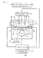
- FIG. 1 is a schematic configuration diagram of a blood cell agglutination image determining apparatus according to an embodiment of the present invention.
- a blood cell agglutination image determining apparatus 1 comprises a casing 2; a rotor 3; a motor 6; an inclining apparatus 7; a CCD camera 8; an image processing section 11; and a control section 12.
- the casing 2 includes a door 2a as a lid for capping in a freely openable and closable manner in the upward direction, and the rotor 3 is positioned within a chamber 2b.
- FIG 2 is a perspective view of the rotor 3.
- the rotor 3 is an H-shaped member having yokes 3b on both sides of a main body 3a, and an insertion hole 3c is formed in the center of the main body 3a.
- Each yoke 3b includes trunnion pins 3d provided therefor at internally opposing positions, where each of the trunnion pins 3d protrudes internally and is a horizontal shaft for horizontally supporting a bucket 4.
- the rotor 3 balances and retains buckets 4 on both sides of the main body 3a by means of the trunnion pins 3d illustrated in Figure 2 .
- the bucket 4 functions as a reaction container housing section for housing a reaction container, such as a microplate 5.
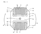
- Figure 3 is a perspective view of a rotor 3 having buckets 4 attached thereto.
- Figure 4 is a plane view of a rotor 3 having buckets 4 attached thereto, where a microplate 5 is set with each bucket 4.
- the bucket 4 is a rectangular parallelepiped casing with an opened upper part and with an opening 4a formed on a bottom surface thereof.
- the bucket 4 includes an engagement groove 4b formed at a position slightly displaced towards the outer circumference of the rotor 3 from the center, and between the trunnion pins 3d on both sides.
- Each trunnion pin 3d is engaged with the engagement groove 4b so that the bucket 4 will be supported by the rotor 3 as illustrated in Figure 3 , and the bucket 4 swings as illustrated by the arrow As with trunnion pins (not shown) as the center. Additionally, as illustrated in Figure 4 , the bucket 4 retains the microplate 5 and rotates in the direction illustrated by the arrow Ar together with the rotor 3 , with the insertionhole 3c as the center. During the rotation, the engagement groove 4b of the bucket 4 is slightly displaced towards the outer circumference of the rotor 3. Thus, as the rotor 3 rotates, the side of the bucket 4 closer to the internal circumference of the rotor 3 swings downwards together with the microplate 5, with the trunnion pins 3d as the center.
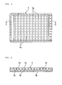
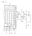
- Figure 5 is a plane view of a microplate.
- Figure 6 is a cross sectional view along the line C-C in Figure 5 .
- Figure 7 is a perspective view illustrating an enlarged cross section of a well formed in a microplate.
- the structure of the microplate will be described with reference to Figures 5 to 7 .
- the microplate 5 comprises 12 x 10 wells 5a formed and arranged therein in a matrix.
- a well 5a is a very small reaction container, in which a dispensed blood sample and a dispensed reagent react with each other, and as illustrated in Figure 6 , the well 5a has abottomwall 5b, the inner surface of which has a substantially conical shape.
- the motor 6 constitutes a rotationmechanism R for rotating the microplate 5, and the motor 6 rotates the rotor 3 to move blood cells contained in the blood sample or reagent dispensed in each well 5a towards the bottom wall 5b.
- the motor 6 comprises the rotor 3 attached thereto by a nut (not shown) screwed into an upper end of a rotation shaft 6a inserted into the insertion hole 3c.
- the inclining apparatus 7 is provided for each bucket 4, and is means for inclining the microplate 5, with a shorter side Ss (see Figure 4 ), positioned in the front of the bucket 4 along the rotating direction, to be downwards with respect to the vertical direction.
- the inclining apparatus 7 is provided at a position facing the bucket 4 at the side surface of the chamber 2b, and the inclining apparatus 7 comprises a chuck 71, a revolving motor 72 and an elevating device 73.
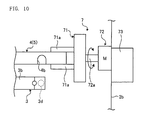
- the chuck 71 holds an outer edge of the longer side of the bucket 4 by two holding pawls 71a (see Figure 10 ) .
- the revolving motor 72 comprises a revolving shaft 72a (see Figure 10 ), and revolves the chuck 71 provided at the end portion of the revolving shaft 72a to incline the bucket 4 so that the shorter side Ss (see Figure 4 ) of the microplate 5 in the front of the rotating direction will be downwards with respect to the vertical direction.
- the elevating device 73 elevates the rotation motor 72 using a ball screw, and the rotation motor 72 is attached to a slider (not shown).
- a CCD camera 8 is means for capturing images of a plurality of wells 5a of a microplate 5, and the CCD camera 8 outputs image signals of a plurality of captured wells 5a to an image processing section 11.
- the CCD camera 8 is provided at a position facing the microplate 5 that is rotated by the rotor 3 below the door 2a.
- the inclining apparatus 7 and the CCD camera 8 are arranged at positions apart from each other at the central angle of 90 degrees along the rotational locus of the microplate 5.
- a lighting 9 is lighting means, such as a fluorescent lamp, provided for a lower part of the inner wall of the chamber 2b, for lighting the microplate 5 from below.
- the image processing section 11 performs image processing on an image of each well 5a on the basis of the image signals of the plurality of wells 5a that are inputted from the CCD camera 8, calculates a determination value for each well 5a, and outputs the thus obtained determination value for each well 5a to a determination section 12a.
- the control section 12 controls respective sections by providing instructions of operation timing, transferring data, or the like to the respective sections that constitute the blood cell agglutination image determining apparatus 1, to control the operation of the overall blood cell agglutination image determining apparatus 1 collectively.
- the control section 12 constitutes a microcomputer or the like with a built-in memory for retaining various data necessary for the operation of the blood cell agglutination image determining apparatus 1, in addition to determination results regarding the blood type of each blood sample on the basis of the determination result of each well 5a or determination results of a plurality of wells 5a; and as illustrated in Figure 1 , the control section 12 comprises the determination section 12a.
- the determination section 12a determines a blood sample with three stages of strongly positive, weak positive or negative for each well 5a, wherein strongly positive is where blood cell agglutination has occurred the most, on the basis of the determination value for each well 5a input from the image processing section 11.
- the blood cell agglutination image determining apparatus 1 dispenses undiluted blood plasma, or blood plasma diluted down to a predetermined concentration with physiological saline, and determines the blood sample to be either positive or negative for each well 5a of the microplate 5 on the basis of an agglutination image resulted from the reaction between the blood plasma and blood cells when the blood cells were dispensed at a predetermined ratio.
- a reaction step of allowing a blood sample and a reagent to react with each other in a reaction container may be in progress at any time in relation to a centrifugation processing step and an inclination step. The reaction step may be in progress prior to either or both of those steps, or the reaction step may be in progress in parallel to, or after, those steps.
- red blood cells taken from blood are used as a blood sample, and an anti-A antibody and an anti-B antibody for determining the blood type are used as reagents.
- the blood plasma (blood serum) is used as a blood sample, and a type-A red blood cell suspension and a type-B red blood cell suspension are used as reagents, where type-A red blood cells of blood of a known blood type are suspended in physiological saline, and type-B red blood cells of blood of a known blood type are suspended in physiological saline.
- a type-A red blood cell suspension and a type-B red blood cell suspension are used as reagents, where type-A red blood cells of blood of a known blood type are suspended in physiological saline, and type-B red blood cells of blood of a known blood type are suspended in physiological saline.
- the blood plasma (blood serum) of an object for determination is dispensed to two wells 5a, then the type-A red blood cell suspension and the type-B red blood cell suspension are dispensed in these two wells 5a, and the microplate 5 after the dispensing is attached to a bucket 4. Then, the door 2a of the blood cell agglutination image determining apparatus 1 is opened upwards, and two of such buckets 4 each having a microplate 5 attached thereto are retained by the rotor 3 within the chamber 2b.
- the engagement groove 4b (see Figure 10 ) of the bucket 4 is engaged with the trunnion pins 3d, so that the bucket 4 is supported by the trunnionpins 3d as illustrated in Figure 4 .
- the rotor 3 retains two microplates 5 in a point symmetry manner in relation to the insertion hole 3c of the rotor 3, which is the center of rotation.
- the operator closes the door 2a of the blood cell agglutination image determining apparatus 1, turns on the switch of the blood cell agglutination image determining apparatus 1, and presses a blood cell agglutination process determining button. Then, in accordance with a pre-set program, the blood cell agglutination image determining apparatus 1 drives the motor 6 to rotate the rotor 3, thus performing centrifugation processing on the microplates 5.
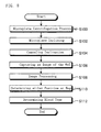
- a blood cell agglutination image determining method according to the present invention will be described in detail on the basis of the flowchart illustrated in Figure 8 .
- the blood cell agglutination image determining apparatus 1 rotates the rotor 3 to perform centrifugation processing on the microplates 5 (step S100). While blood cells are separated out towards the side closer to the bottom wall 5b by the centrifugation processing, the control section 12 controls the rotation of the microplates 5 by the motor 6 so that the blood cells will not be completely pressed against the bottom wall 5b. For such controlling, the control section 12 controlled the motor 6 so that the rotor 3 rotated at a rotation rate of 1,000 rotations per minute (200G) for 15 seconds.
- an agglutination reaction starts due to the antigen-antibody reaction between antibodies present in the blood plasma (blood serum) and antigen epitope present on the surfaces of the red blood cells.
- blood plasma blood serum
- an agglutination mass produced due to the agglutination reaction are included in the blood cells moving towards the side closer to the bottom wall 5b.
- Figure 9 is a front view for describing state of a bucket 4 in relation to the rotation of the rotor 3 in the blood cell agglutination image determining apparatus 1.
- the bucket 4 At the start of the rotation of the motor 6, the bucket 4 is in such a state where the upper surface of the rotor 3 and the upper surface of the bucket 4 are flush.
- the lower part of the bucket 4 swings outwards from the rotor 3, due to the working centrifugal force, with the trunnion pins 3d as the center; and as illustrated in Figure 9 (a) , the side of the bucket 4 closer to the internal circumference of the rotor 3 moves downwards while the side closer to the outer circumference moves upwards.
- the blood cell agglutination image determining apparatus 1 inclines each microplate 5 so that the shorter side Ss (see Figure 4 ) of the microplate 5 in the front of the rotating direction will be downwards with respect to the vertical direction (step S102).
- Figure 10 is a front view illustrating a state where the bucket 4 is detached from the rotor 3 by the inclining apparatus 7.
- Figure 11 is a front view illustrating a state where the bucket 4 is inclined by the inclining apparatus 7.
- the inclining operation of the microplate 5 by the inclining apparatus 7 will be described with reference to Figures 10 and 11 .
- the blood cell agglutination image determining apparatus 1 drives the inclining apparatus 7 so that the chuck 71 holds the outer edge of the longer side of the bucket 4 by two holding pawls 71a. Thereafter, the revolving motor 72 is raised by the elevating device 73, and the bucket 4 is detached from the rotor 3 as illustrated in Figure 10 . Then, the blood cell agglutination image determining apparatus 1 drives the revolving motor 72 to revolve the chuck 71, and as illustrated in Figure 11 , retains the bucket 4 to be inclined for two minutes at 90 degrees in relation to the horizontal plane so that the shorter side Ss (see Figure 4 ) of the microplate 5 in the front of the rotating direction will be downwards with respect to the vertical direction.
- the blood cell agglutination image determining apparatus 1 drives the inclining apparatus 7 in the opposite direction from the description above to allow the rotor 3 to retain the bucket 4, and the incline of the microplate 5 is canceled (step S104) .
- the microplate 5 is retained horizontally with the bucket 4 (see Figure 4 ).
- the blood cell agglutination image determining apparatus 1 allows the CCD camera 8 to capture images of a plurality of the wells 5a of the microplate 5 (step S106) .
- the image processing section 11 performs image processing on the image for each well 5a including a reaction image (step S108).
- the image processing section 11 performs calculation, for example, with a determination parameter P/C of an agglutination reaction, which is obtained by multiplying a value Lp/Lc of the ratio between an average amount of light Lp in the periphery part and an average amount of light Lc in the center part of a well 5a by ten, as a determination value.
- a determination parameter P/C of an agglutination reaction which is obtained by multiplying a value Lp/Lc of the ratio between an average amount of light Lp in the periphery part and an average amount of light Lc in the center part of a well 5a by ten, as a determination value.
- the blood plasma blood serum
- red blood cells will precipitate at the deepest part in the center of the bottom wall 5b of the well 5a, without causing an agglutination reaction.
- the red blood cells are defined to be halfway between agglutination and non-agglutination.
- the difference between the average amount of light Lp in the periphery part P and the average amount of light Lc in the center part C of the well 5a becomes comparatively smaller than the case of the negative sample illustrated in Figure 12 .
- the value of the determination parameter P/C becomes within the range of 15 to 30.
- the blood plasma (blood serum) is a strongly positive sample indicating a strong reactivity with respect to red blood cells for example, then a fine agglutination mass is produced due to a reaction between the antigen present on the surfaces of red blood cells and the antibody present in the blood plasma (blood serum).
- blood plasma blood serum
- the average amount of light Lp in the periphery part P of the well 5a and the average amount of light Lc in the center part C of the well 5a are almost equal in the reaction image of the well 5a.
- the value of the determination parameter P/C becomes within the range of 10 to 15. If the value of the determination parameter P/C becomes within the range of 30 to 40, then automatic determination cannot be made.
- the determination section 12a determines the blood plasma (blood serum) to be either positive or negative for each well 5a on the basis of the determination parameter P/C calculated by the image processing section 11 (step S110). Then, the determination section 12a determines the blood type of the blood plasma (blood serum) on the basis of the determination result made for each well 5a (step S112).
- the operator opens the door 2a of the blood cell agglutination image determining apparatus 1 upwards, and detaches the bucket 4 retaining the microplate 5 from the rotor 3.
- the microplate 5 is removed from the bucket 4, and then the bucket 4 retains a new microplate 5, in which new blood plasma (blood serum) of an object for determination is dispensed to two wells 5a, then a type-A red blood cell suspension and a type-B red blood cell suspension are dispensed in these two wells 5a.
- the bucket 4 retaining the new microplate 5 is supported by the rotor 3 within the chamber 2b to repeat the blood cell agglutination image determining method.
- the microplate 5 is rotated to separate blood cells out towards the side closer to the bottom wall 5b, and then, the microplate 5 is inclined so that the side of the microplate 5 in the front of the rotating direction will be downwards with respect to the vertical direction to allow the reagent to react with the blood sample, and on the basis of the reaction image, the blood sample is determined to be either positive or negative for each well 5a.
- the present invention requires only 15 seconds for the centrifugation processing to move blood cells towards the side closer to the bottom wall 5b of the microplate 5, and requires only 2 minutes to incline the microplate 5 and allow the reagent to react with the blood sample.
- the present invention is capable of processing blood samples in a shorter time compared to the conventionally performed tube tests, column agglutination technology, or plate settling methods, thereby obtaining a reproducible determination result. Further, since the present invention determines the blood sample to be either positive or negative by centrifugation processing and inclination processing of the microplate into which the blood sample and reagent are dispensed, the determination can be performed at lower cost compared to the conventionally utilized tube tests or column agglutination technology.
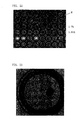
- Figure 15 is a diagram of an image captured by the CCD camera 8 of a microplate 5 immediately after centrifugation processing is performed by the blood cell agglutination image determining apparatus 1.
- the right direction illustrated by the arrow in the figure is the rotation direction of the microplate 5.
- 25 ⁇ L of blood plasma (blood serum) of an object for determination and 25 ⁇ L of a red blood cell suspension as a reagent are dispensed into each of a total of eight wells 5a, the wells 5a being in the fourth and fifth rows from the top and in the second to fifth columns from the left.
- 0.43% of the red blood cell suspension is dispensed into the wells 5a in the fourth row from the top, and 0.85% of the red blood cell suspension is dispensed into the wells 5a in the fifth row.
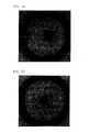
- Figure 16 is a diagram of an image captured by the CCD camera 8 of a microplate 5 after centrifugation processing and further inclination for two minutes.
- Figure 17 is a diagram of determination results of the images illustrated in Figure 16 together with the concentration of the red blood cell suspensions.
- the image processing section 11 processed the image for each of the total of eight wells 5a of the microplate 5, including the reaction image captured by the CCD camera 8, and the determination section 12a determined the blood plasma (blood serum) to be either positive or negative on the basis of the obtained determination value for each well 5a.
- the determination parameter the amount of transmitted light at the center part of the well can be applied, but it is also possible to combine it with other parameters for determination.
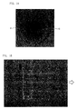
- Figures 18 to 20 are diagrams of an enlarged view of the strongly positive well 5a (W2) in the fifth row, second column; an enlarged view of the weak positive well 5a (W3) in the fifth row, third column; and an enlarged view of the negative well 5a (W5) in the fifth row, fifth column, among the images illustrated in Figure 17 .
- the blood samples were able to be processed in a short time, thereby obtaining a reproducible determination result, and furthermore, the strongly positive, weak positive and negative blood samples were able to be clearly and mutually determined in a visual manner.
- weak positive and negative results were able to be clearly and mutually determined in a visual manner, which had been conventionally said to be difficult to determine.
- the blood cell agglutination image determining method according to the present invention and a tube test, as a comparative example of the present invention were used to determine a blood sample three times each.
- the intensity of agglutination is represented in such a manner as "1+” and "2+", where "2+” represents a weak positive image that can be comparatively easily determined from negative, while "1+” represents a weak positive image that requires some level of performance to determine the sample as positive (see Non-Patent Literature 1) .
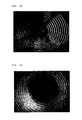
- the blood cell agglutination image determining method was performed under the same conditions as described above by the blood cell agglutination image determining apparatus 1, using a microplate having the same number of wells W as the microplate 5, except that the inner surface of each bottom wall is processed to be a smooth U-shape and adj acent wells are closer to each other. The result thereof will be illustrated in Figures 21 to 25 .
- Figure 21 is a diagram of an image captured by the CCD camera 8 of the microplate immediately after centrifugation processing is performed.
- the right direction illustrated by the arrow in the figure is the rotation direction of the microplate.
- 25 ⁇ L of blood plasma (blood serum) of an object for determination and 25 ⁇ L of a red blood cell suspension as a reagent were dispensed into each of a total of 16 wells W in two adjacent rows.
- 1.7% of the red blood cell suspension was dispensed in the wells W on the upper row, and 0.85% of the red blood cell suspension was dispensed into the wells W on the lower row.
- undiluted blood plasma (blood serum) was used for the four columns on the left side, and two-fold diluted blood plasma (blood serum) that was diluted with physiological saline was used for the four columns on the right side.
- Figure 22 is a diagram of an image captured by the CCD camera 8 of the microplate after being inclined for two minutes by the inclining apparatus 7.
- Figure 23 is an enlarged view of a well W1 in the fourth row, first column in Figure 22
- Figure 24 is an enlarged view of a well W2 in the fourth row, second column thereof
- Figure 25 is an enlarged view of a well W4 in the fourth row, fourth column thereof.
- the microplate 5 may be taken out of the blood cell agglutination image determining apparatus 1 to make a determination of being positive or negative by visual observation.
- making a determination in the blood cell agglutination image determining apparatus 1 provides an advantage of obtaining a determination result on the basis of a constant standard.
- the embodiment is not limited to this.
- the average amount of light Lc in the center part C, or other determination parameters may be used, and moreover, it is also possible to combine and use these determination parameters to determine if a blood sample is positive or negative.
- reaction container 5a of the microplate 5 are used as reaction containers in the embodiment described above, a reaction container of an individually independent well 5a may be used instead of the wells 5a.
- a control program for controlling the processing executed by the blood cell agglutination image determining apparatus 1 is installed on a storage section (not shown) of the control mechanism 12 illustrated in Figure 1 .
- installing such a control program on a memory of a computer allows the computer to function as a part or all of the control section 12 ( Figure 1 ).
- Such a control program may be installed on a memory prior to the shipping of the computer, or may be installed on a memory after the shipment of the computer.
- the program may be installed on a memory of the computer by reading the program recorded on a recording medium, or the program that is downloaded via a network, such as the Internet, may be installed on a memory.
- any type of computer can be used.
- control section 12 ( Figure 1 ) in operation means that a control method corresponding to the installed control program is being executed. This is because the control method corresponds to the operation method of the control mechanism.
- the blood cell agglutination image determining apparatus and blood cell agglutination image determining method according to the present invention are useful for processing and determining a blood sample in a simple manner and in a shorter time.
Landscapes
- Health & Medical Sciences (AREA)
- Life Sciences & Earth Sciences (AREA)
- Engineering & Computer Science (AREA)
- Chemical & Material Sciences (AREA)
- Physics & Mathematics (AREA)
- Immunology (AREA)
- Biomedical Technology (AREA)
- Hematology (AREA)
- General Health & Medical Sciences (AREA)
- Analytical Chemistry (AREA)
- Pathology (AREA)
- General Physics & Mathematics (AREA)
- Biochemistry (AREA)
- Urology & Nephrology (AREA)
- Molecular Biology (AREA)
- Food Science & Technology (AREA)
- Medicinal Chemistry (AREA)
- Biotechnology (AREA)
- Ecology (AREA)
- Biophysics (AREA)
- Spectroscopy & Molecular Physics (AREA)
- Cell Biology (AREA)
- Microbiology (AREA)
- Chemical Kinetics & Catalysis (AREA)
- Plasma & Fusion (AREA)
- Investigating Or Analysing Biological Materials (AREA)
- Investigating Or Analysing Materials By Optical Means (AREA)
- Automatic Analysis And Handling Materials Therefor (AREA)
Applications Claiming Priority (2)
| Application Number | Priority Date | Filing Date | Title |
|---|---|---|---|
| JP2009293376A JP2011133364A (ja) | 2009-12-24 | 2009-12-24 | 血球凝集像判定方法及び血球凝集像判定装置 |
| PCT/JP2010/007451 WO2011077728A1 (ja) | 2009-12-24 | 2010-12-22 | 血球凝集像判定方法及び血球凝集像判定装置 |
Publications (1)
| Publication Number | Publication Date |
|---|---|
| EP2518502A1 true EP2518502A1 (en) | 2012-10-31 |
Family
ID=44195281
Family Applications (1)
| Application Number | Title | Priority Date | Filing Date |
|---|---|---|---|
| EP10838966A Withdrawn EP2518502A1 (en) | 2009-12-24 | 2010-12-22 | Method for determining hemagglutination image and device for determining hemagglutination image |
Country Status (5)
| Country | Link |
|---|---|
| US (1) | US20120288887A1 (enExample) |
| EP (1) | EP2518502A1 (enExample) |
| JP (1) | JP2011133364A (enExample) |
| CN (1) | CN102687017A (enExample) |
| WO (1) | WO2011077728A1 (enExample) |
Cited By (1)
| Publication number | Priority date | Publication date | Assignee | Title |
|---|---|---|---|---|
| WO2015052162A3 (en) * | 2013-10-09 | 2015-06-18 | Yantai Ausbio Laboratories Co., Ltd. | Method for determining the result of an agglutination reaction and microplate for determining products of agglutination reactions |
Families Citing this family (9)
| Publication number | Priority date | Publication date | Assignee | Title |
|---|---|---|---|---|
| CN103487377B (zh) * | 2013-10-11 | 2016-03-09 | 江苏英诺华医疗技术有限公司 | 一种全血凝血功能检测仪及检测方法 |
| EP2929939A1 (en) * | 2014-04-07 | 2015-10-14 | Yantai AusBio Laboratories Co., Ltd. | Microplate |
| US10429401B2 (en) | 2014-07-21 | 2019-10-01 | Beckman Coulter, Inc. | Methods and systems for tube inspection and liquid level detection |
| CN107167616B (zh) * | 2017-03-13 | 2019-06-07 | 中国科学院苏州生物医学工程技术研究所 | 血型检测方法及装置 |
| CN113614532A (zh) * | 2019-01-16 | 2021-11-05 | 烟台澳斯邦生物工程有限公司 | 沉积用于显微镜检查的生物样品的自动液体处理系统和方法 |
| CN109932517B (zh) * | 2019-04-04 | 2022-03-11 | 烟台海深威医学技术有限公司 | 一种血液凝集判断方法及装置 |
| CN110286239A (zh) * | 2019-08-12 | 2019-09-27 | 杭州美川合佳生物科技有限公司 | 一种血型全自动分析装置 |
| CN110780080B (zh) * | 2019-11-08 | 2024-07-12 | 安邦(厦门)生物科技有限公司 | 一种血型分析仪及血型分析方法 |
| JP7470587B2 (ja) * | 2020-07-14 | 2024-04-18 | 株式会社日立製作所 | 検体性状判別装置及び検体性状判別方法 |
Family Cites Families (13)
| Publication number | Priority date | Publication date | Assignee | Title |
|---|---|---|---|---|
| JPS5811835A (ja) * | 1981-07-16 | 1983-01-22 | Olympus Optical Co Ltd | 粒子凝集判定装置および判定容器 |
| EP0396115A3 (en) * | 1989-05-03 | 1991-07-24 | Abbott Laboratories | Method of forming agglutinates in blood samples |
| JPH03110468A (ja) * | 1989-09-26 | 1991-05-10 | Anariiteikaru Instr:Kk | 遠心式免疫凝集自動判定装置 |
| JP2683944B2 (ja) * | 1989-12-21 | 1997-12-03 | 富士レビオ株式会社 | 間接凝集免疫測定方法及び装置 |
| US6258607B1 (en) * | 1989-10-31 | 2001-07-10 | Fujirebio Inc. | Indirect agglutination immunoassay and apparatus therefor |
| JPH05172816A (ja) * | 1991-05-13 | 1993-07-13 | Denka Seiken Co Ltd | 抗原の測定方法 |
| US5541417A (en) * | 1995-05-18 | 1996-07-30 | Abbott Laboratories | Quantative agglutination reaction analysis method |
| JP2883064B2 (ja) * | 1997-12-19 | 1999-04-19 | オリンパス光学工業株式会社 | 分布パターンの形成方法および装置 |
| JPH11271308A (ja) * | 1998-03-20 | 1999-10-08 | Olympus Optical Co Ltd | 分析装置 |
| JP2001133397A (ja) * | 1999-11-05 | 2001-05-18 | Fujirebio Inc | 検体の検査装置 |
| JP2002286719A (ja) * | 2001-03-23 | 2002-10-03 | Olympus Optical Co Ltd | 複数のパラメータを用いて凝集反応を解析評価する方法およびその方法に用いる容器 |
| JP4469990B2 (ja) * | 2007-04-19 | 2010-06-02 | ベックマン・コールター・インコーポレーテッド | 粒子凝集判定用容器 |
| CN103424543B (zh) * | 2007-10-04 | 2015-04-29 | 松下健康医疗器械株式会社 | 采用分析用仪器的分析方法 |
-
2009
- 2009-12-24 JP JP2009293376A patent/JP2011133364A/ja not_active Withdrawn
-
2010
- 2010-12-22 WO PCT/JP2010/007451 patent/WO2011077728A1/ja not_active Ceased
- 2010-12-22 CN CN2010800586338A patent/CN102687017A/zh active Pending
- 2010-12-22 EP EP10838966A patent/EP2518502A1/en not_active Withdrawn
-
2012
- 2012-06-21 US US13/530,041 patent/US20120288887A1/en not_active Abandoned
Non-Patent Citations (1)
| Title |
|---|
| See references of WO2011077728A1 * |
Cited By (3)
| Publication number | Priority date | Publication date | Assignee | Title |
|---|---|---|---|---|
| WO2015052162A3 (en) * | 2013-10-09 | 2015-06-18 | Yantai Ausbio Laboratories Co., Ltd. | Method for determining the result of an agglutination reaction and microplate for determining products of agglutination reactions |
| EP3326718A1 (en) | 2013-10-09 | 2018-05-30 | Yantai AusBio Laboratories Co., Ltd. | Microplate for determining products of agglutination reactions |
| US10895570B2 (en) | 2013-10-09 | 2021-01-19 | Yantai Ausbio Laboratories Co., Ltd. | Method for determining the result of an agglutination reaction and microplate for determining products of agglutination reactions |
Also Published As
| Publication number | Publication date |
|---|---|
| JP2011133364A (ja) | 2011-07-07 |
| CN102687017A (zh) | 2012-09-19 |
| US20120288887A1 (en) | 2012-11-15 |
| WO2011077728A1 (ja) | 2011-06-30 |
Similar Documents
| Publication | Publication Date | Title |
|---|---|---|
| EP2518502A1 (en) | Method for determining hemagglutination image and device for determining hemagglutination image | |
| JP5329293B2 (ja) | 遠心分離サイクル中の凝集評価を事前に提供するための少なくとも1つのイメージャーを有する免疫診断検査装置 | |
| US11119048B2 (en) | Chemiluminescence detection equipment and its operation method | |
| US11555823B2 (en) | Medical analysis method | |
| US8999729B2 (en) | Device and analyzing system for conducting agglutination assays | |
| RU2663042C2 (ru) | Микропланшет | |
| CN105612002B (zh) | 用于测定凝集反应结果的方法和用于测定凝集反应产物的微孔板 | |
| JPH07505473A (ja) | 自動連続ランダム・アクセス分析システムおよびその構成要素 | |
| JPH03135768A (ja) | 分析法及び自動分析装置 | |
| AU2004200710A2 (en) | Detection of agglutination of assays | |
| US6582912B1 (en) | Device, method and apparatus for implementing the method, for dosing at least a particular constituent in a product sample | |
| US5721141A (en) | Tube washing system | |
| WO2002037078A2 (en) | Automated immunoassay analyzer and method of using the same | |
| US11946926B2 (en) | Method and apparatus for testing a biological sample | |
| JP2006242872A5 (enExample) | ||
| JP6953678B2 (ja) | 有形成分分析装置及び有形成分分析方法 | |
| JPS5811858A (ja) | 免疫学的凝集反応に基く分析装置 | |
| HK40010421B (en) | Method and apparatus for testing a biological sample |
Legal Events
| Date | Code | Title | Description |
|---|---|---|---|
| PUAI | Public reference made under article 153(3) epc to a published international application that has entered the european phase |
Free format text: ORIGINAL CODE: 0009012 |
|
| 17P | Request for examination filed |
Effective date: 20120614 |
|
| AK | Designated contracting states |
Kind code of ref document: A1 Designated state(s): AL AT BE BG CH CY CZ DE DK EE ES FI FR GB GR HR HU IE IS IT LI LT LU LV MC MK MT NL NO PL PT RO RS SE SI SK SM TR |
|
| DAX | Request for extension of the european patent (deleted) | ||
| STAA | Information on the status of an ep patent application or granted ep patent |
Free format text: STATUS: THE APPLICATION HAS BEEN WITHDRAWN |
|
| 18W | Application withdrawn |
Effective date: 20131209 |