EP2518372B1 - Fahrzeug und steuerungsverfahren dafür - Google Patents
Fahrzeug und steuerungsverfahren dafür Download PDFInfo
- Publication number
- EP2518372B1 EP2518372B1 EP10839060.0A EP10839060A EP2518372B1 EP 2518372 B1 EP2518372 B1 EP 2518372B1 EP 10839060 A EP10839060 A EP 10839060A EP 2518372 B1 EP2518372 B1 EP 2518372B1
- Authority
- EP
- European Patent Office
- Prior art keywords
- torque
- clamping force
- transmission member
- continuously variable
- rotation
- Prior art date
- Legal status (The legal status is an assumption and is not a legal conclusion. Google has not performed a legal analysis and makes no representation as to the accuracy of the status listed.)
- Not-in-force
Links
Images


Classifications
-
- F—MECHANICAL ENGINEERING; LIGHTING; HEATING; WEAPONS; BLASTING
- F16—ENGINEERING ELEMENTS AND UNITS; GENERAL MEASURES FOR PRODUCING AND MAINTAINING EFFECTIVE FUNCTIONING OF MACHINES OR INSTALLATIONS; THERMAL INSULATION IN GENERAL
- F16H—GEARING
- F16H61/00—Control functions within control units of change-speed- or reversing-gearings for conveying rotary motion ; Control of exclusively fluid gearing, friction gearing, gearings with endless flexible members or other particular types of gearing
- F16H61/66—Control functions within control units of change-speed- or reversing-gearings for conveying rotary motion ; Control of exclusively fluid gearing, friction gearing, gearings with endless flexible members or other particular types of gearing specially adapted for continuously variable gearings
- F16H61/662—Control functions within control units of change-speed- or reversing-gearings for conveying rotary motion ; Control of exclusively fluid gearing, friction gearing, gearings with endless flexible members or other particular types of gearing specially adapted for continuously variable gearings with endless flexible members
- F16H61/66272—Control functions within control units of change-speed- or reversing-gearings for conveying rotary motion ; Control of exclusively fluid gearing, friction gearing, gearings with endless flexible members or other particular types of gearing specially adapted for continuously variable gearings with endless flexible members characterised by means for controlling the torque transmitting capability of the gearing
-
- F—MECHANICAL ENGINEERING; LIGHTING; HEATING; WEAPONS; BLASTING
- F16—ENGINEERING ELEMENTS AND UNITS; GENERAL MEASURES FOR PRODUCING AND MAINTAINING EFFECTIVE FUNCTIONING OF MACHINES OR INSTALLATIONS; THERMAL INSULATION IN GENERAL
- F16H—GEARING
- F16H55/00—Elements with teeth or friction surfaces for conveying motion; Worms, pulleys or sheaves for gearing mechanisms
- F16H55/02—Toothed members; Worms
- F16H55/14—Construction providing resilience or vibration-damping
-
- F—MECHANICAL ENGINEERING; LIGHTING; HEATING; WEAPONS; BLASTING
- F16—ENGINEERING ELEMENTS AND UNITS; GENERAL MEASURES FOR PRODUCING AND MAINTAINING EFFECTIVE FUNCTIONING OF MACHINES OR INSTALLATIONS; THERMAL INSULATION IN GENERAL
- F16H—GEARING
- F16H57/00—General details of gearing
- F16H57/0006—Vibration-damping or noise reducing means specially adapted for gearings
-
- F—MECHANICAL ENGINEERING; LIGHTING; HEATING; WEAPONS; BLASTING
- F16—ENGINEERING ELEMENTS AND UNITS; GENERAL MEASURES FOR PRODUCING AND MAINTAINING EFFECTIVE FUNCTIONING OF MACHINES OR INSTALLATIONS; THERMAL INSULATION IN GENERAL
- F16H—GEARING
- F16H9/00—Gearings for conveying rotary motion with variable gear ratio, or for reversing rotary motion, by endless flexible members
- F16H9/02—Gearings for conveying rotary motion with variable gear ratio, or for reversing rotary motion, by endless flexible members without members having orbital motion
- F16H9/04—Gearings for conveying rotary motion with variable gear ratio, or for reversing rotary motion, by endless flexible members without members having orbital motion using belts, V-belts, or ropes
- F16H9/12—Gearings for conveying rotary motion with variable gear ratio, or for reversing rotary motion, by endless flexible members without members having orbital motion using belts, V-belts, or ropes engaging a pulley built-up out of relatively axially-adjustable parts in which the belt engages the opposite flanges of the pulley directly without interposed belt-supporting members
- F16H9/16—Gearings for conveying rotary motion with variable gear ratio, or for reversing rotary motion, by endless flexible members without members having orbital motion using belts, V-belts, or ropes engaging a pulley built-up out of relatively axially-adjustable parts in which the belt engages the opposite flanges of the pulley directly without interposed belt-supporting members using two pulleys, both built-up out of adjustable conical parts
- F16H9/18—Gearings for conveying rotary motion with variable gear ratio, or for reversing rotary motion, by endless flexible members without members having orbital motion using belts, V-belts, or ropes engaging a pulley built-up out of relatively axially-adjustable parts in which the belt engages the opposite flanges of the pulley directly without interposed belt-supporting members using two pulleys, both built-up out of adjustable conical parts only one flange of each pulley being adjustable
Claims (12)
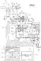
- Ein Fahrzeug (1), das folgende Merkmale aufweist:einen Motor (20);ein kontinuierlich veränderliches Getriebe (30) zum Empfangen eines Drehmoments von dem Motor (20), das eine stationäre Scheibe (31 b, 32b), eine bewegbare Scheibe (31 a, 32a), die gegenüber der stationären Scheibe (31 b, 32b) vorgesehen ist und in der Lage ist, sich relativ zu derselben zu bewegen, und eine Betätigungsvorrichtung (51 a, 52a) zum Bewegen der bewegbaren Scheibe (31 a, 32a) umfasst;eine Steuervorrichtung (10) zum Antreiben der Betätigungseinrichtung (51a, 52a), um eine Klemmkraft zu steuern, die eine Kraft zum Klemmen eines Riemens (33) durch die stationäre Scheibe (31 b, 32b) und die bewegbare Scheibe (31 a, 32a) darstellt;ein Antriebsrad (3) zum Empfangen eines Drehmoments von dem kontinuierlich veränderlichen Getriebe (30); undeinen Drehmomentdämpfungsmechanismus (9), der auf einem Drehmomentübertragungsweg zwischen dem kontinuierlich veränderlichen Getriebe (30) und dem Antriebsrad (3) vorgesehen ist, zum Verzögern einer Zeitsteuerung für eine Übertragung einer Drehmomentfluktuation mit einer negativen Winkelbeschleunigung, die an einem nachgeschalteten Drehmomentübertragungsbauglied (37) auftritt, das nachgeschaltet zu dem Drehmomentdämpfungsmechanismus (9) positioniert ist, zu einem vorgeschalteten Drehmomentübertragungsbauglied (34), das vorgeschaltet zu dem Drehmomentdämpfungsmechanismus (9) positioniert ist, indem eine Drehrichtung des nachgeschalteten Drehmomentübertragungsbauglieds (37) als positiv definiert wird,dadurch gekennzeichnet, dass die Steuervorrichtung (10) folgende Merkmale umfasst:eine Zustandsinformationenerhaltungseinheit (46) zum Erhalten, als Informationen, die einen Zustand des Drehmomentdämpfungsmechanismus (9) beschreiben, vonInformationen über die Drehung des vorgeschalteten Drehmomentübertragungsbauglieds (34) und Informationen über die Drehung des nachgeschalteten Drehmomentübertragungsbauglieds (37), oderPositionsinformationen über ein Verschiebungsbauglied (94) in dem Drehmomentdämpfungsmechanismus (9), das sich gemäß einer Beziehung zwischen einem Drehmoment des vorgeschalteten Drehmomentübertragungsbauglieds (34) und einem Drehmoment des nachgeschalteten Drehmomentübertragungsbauglieds (37) bewegt, undeine Klemmkraftänderungsverarbeitungseinheit (42i) zum Erhöhen der Klemmkraft, wenn ein Auftreten einer Drehmomentfluktuation an dem nachgeschalteten Drehmomentübertragungsbauglied (37) basierend auf dem Zustand des Drehmomentdämpfungsmechanismus (9) erfasst wird.
- Das Fahrzeug (1) gemäß Anspruch 1, bei dem
die Klemmkraftänderungsverarbeitungseinheit (42i) die Klemmkraft erhöht, wenn eine Phasendifferenz gleich wie oder größer als eine vorbestimmte Phasendifferenz zwischen der Drehung des vorgeschalteten Drehmomentübertragungsbauglieds (34) und der Drehung des nachgeschalteten Drehmomentübertragungsbauglieds (37) verursacht wird. - Das Fahrzeug (1) gemäß Anspruch 1, bei dem
die Klemmkraftänderungsverarbeitungseinheit (42i) die Klemmkraft erhöht, wenn eine Differenz gleich wie oder größer als eine vorbestimmte Differenz zwischen einer Drehgeschwindigkeit des vorgeschalteten Drehmomentübertragungsbauglieds (34) und einer Drehgeschwindigkeit des nachgeschalteten Drehmomentübertragungsbauglieds (37) verursacht wird. - Das Fahrzeug (1) gemäß Anspruch 1, bei dem
die Klemmkraftänderungsverarbeitungseinheit (42i) die Klemmkraft basierend auf einer Position des Verschiebungsbauglieds (94) verändert. - Das Fahrzeug (1) gemäß Anspruch 2 oder 3, das ferner folgende Merkmale aufweist:eine Bremsvorrichtung (100) mit einer Dreherfassungseinheit (101) zum Erfassen einer Drehung des Antriebsrads (3) zum Bremsen des Antriebsrads (3) basierend auf einer Drehgeschwindigkeit des Antriebsrads (3), wobeidie Zustandsinformationserhaltungseinheit (46) die Informationen über die Drehung des nachgeschalteten Drehmomentübertragungsbauglieds (37) von der Dreherfassungseinheit (101) erhält.
- Das Fahrzeug (1) gemäß Anspruch 2 oder 3, bei dem die Zustandsinformationserhaltungseinheit (46) die Informationen über die Drehung des nachgeschalteten Drehmomentübertragungsbauglieds (37) von einer Dreherfassungseinheit (101) zum Erfassen einer Drehung des Antriebsrads (3) erhält.
- Das Fahrzeug (1) gemäß Anspruch 1, das ferner eine Kupplung (61) aufweist, die auf dem Drehmomentübertragungsweg vorgesehen ist, wobei die Klemmkraftänderungsverarbeitungseinheit (42i) die Klemmkraft erhöht, sodass eine Drehmomentkapazität des kontinuierlich veränderlichen Getriebes (30) höher wird als eine Drehmomentkapazität der Kupplung (61).
- Das Fahrzeug (1) gemäß Anspruch 1, bei dem die Klemmkraftänderungsverarbeitungseinheit (42i) die Klemmkraft erhöht, sodass eine Drehmomentkapazität des kontinuierlich veränderlichen Getriebes (30) höher wird als eine Drehmomentkapazität des Drehmomentdämpfungsmechanismus (9).
- Das Fahrzeug (1) gemäß Anspruch 1, bei dem
der Drehmomentdämpfungsmechanismus (9) ein Nockendämpfer ist, der folgende Merkmale umfasst:ein erstes Bauglied (92), das mit dem vorgeschalteten Drehmomentübertragungsbauglied (34) verbunden ist,ein zweites Bauglied (94), das mit dem nachgeschalteten Drehmomentübertragungsbauglied (37) verbunden ist, undein elastisches Bauglied (96) zum Drücken eines konvexen Abschnitts (94c), der entweder auf dem ersten Bauglied (92) oder dem zweiten Bauglied (94) gebildet ist, zu einer Nockenoberfläche (92c) in einem konkaven Abschnitt (92a), der auf dem anderen gebildet ist. - Das Fahrzeug (1) gemäß Anspruch 1, das ferner eine Fliehkraftkupplung (61) aufweist, die auf dem Drehmomentübertragungsweg vorgesehen ist.
- Das Fahrzeug (1) gemäß Anspruch 1, bei dem der Riemen (33) des kontinuierlich veränderlichen Getriebes (30) ein Metallriemen ist.
- Ein Verfahren zum Steuern eines Fahrzeugs (1), das folgende Merkmale umfasst:einen Motor (20),ein kontinuierlich veränderliches Getriebe (30) zum Empfangen eines Drehmoments von dem Motor (20), das eine stationäre Scheibe (31 b, 32b), eine bewegbare Scheibe (31 a, 32a), die gegenüber der stationären Scheibe (31 b, 32b) vorgesehen ist und in der Lage ist, sich relativ zu derselben zu bewegen, und eine Betätigungsvorrichtung (51 a, 52a) zum Bewegen der bewegbaren Scheibe (31 a, 32a) umfasst;eine Steuervorrichtung (10) zum Antreiben der Betätigungseinrichtung (51a, 52a), um eine Klemmkraft zu steuern, die eine Kraft zum Klemmen eines Riemens (33) durch die stationäre Scheibe (31 b, 32b) und die bewegbare Scheibe (31 a, 32a) darstellt;ein Antriebsrad (3) zum Empfangen eines Drehmoments von dem kontinuierlich veränderlichen Getriebe (30); undeinen Drehmomentdämpfungsmechanismus (9), der auf einem Drehmomentübertragungsweg zwischen dem kontinuierlich veränderlichen Getriebe (30) und dem Antriebsrad (3) vorgesehen ist, zum Verzögern einer Zeitsteuerung für eine Übertragung einer Drehmomentfluktuation mit einer negativen Winkelbeschleunigung, die an einem nachgeschalteten Drehmomentübertragungsbauglied (37) auftritt, das nachgeschaltet zu dem Drehmomentdämpfungsmechanismus (9) positioniert ist, zu einem vorgeschalteten Drehmomentübertragungsbauglied (34), das vorgeschaltet zu dem Drehmomentdämpfungsmechanismus (9) positioniert ist, indem eine Drehrichtung des nachgeschalteten Drehmomentübertragungsbauglieds (37) als positiv definiert wird,dadurch gekennzeichnet, dass das Verfahren folgende Schritte umfasst:Erhalten, als Informationen, die einen Zustand des Drehmomentdämpfungsmechanismus (9) beschreiben, vonInformationen über die Drehung des vorgeschalteten Drehmomentübertragungsbauglieds (34) und Informationen über die Drehung des nachgeschalteten Drehmomentübertragungsbauglieds (37), oderPositionsinformationen über ein Verschiebungsbauglied (94) in dem Drehmomentdämpfungsmechanismus (9), das sich gemäß einer Beziehung zwischen einem Drehmoment des vorgeschalteten Drehmomentübertragungsbauglieds (34) und einem Drehmoment des nachgeschalteten Drehmomentübertragungsbauglieds (37) bewegt, undErhöhen der Klemmkraft, wenn ein Auftreten einer Drehmomentfluktuation an dem nachgeschalteten Drehmomentübertragungsbauglied (37) basierend auf dem Zustand des Drehmomentdämpfungsmechanismus (9) erfasst wird.
Applications Claiming Priority (2)
| Application Number | Priority Date | Filing Date | Title |
|---|---|---|---|
| JP2009292220 | 2009-12-24 | ||
| PCT/JP2010/068677 WO2011077823A1 (ja) | 2009-12-24 | 2010-10-22 | 車両及びその制御方法 |
Publications (3)
| Publication Number | Publication Date |
|---|---|
| EP2518372A1 EP2518372A1 (de) | 2012-10-31 |
| EP2518372A4 EP2518372A4 (de) | 2015-07-01 |
| EP2518372B1 true EP2518372B1 (de) | 2017-01-04 |
Family
ID=44195368
Family Applications (1)
| Application Number | Title | Priority Date | Filing Date |
|---|---|---|---|
| EP10839060.0A Not-in-force EP2518372B1 (de) | 2009-12-24 | 2010-10-22 | Fahrzeug und steuerungsverfahren dafür |
Country Status (4)
| Country | Link |
|---|---|
| US (1) | US8753248B2 (de) |
| EP (1) | EP2518372B1 (de) |
| JP (1) | JP5685200B2 (de) |
| WO (1) | WO2011077823A1 (de) |
Families Citing this family (4)
| Publication number | Priority date | Publication date | Assignee | Title |
|---|---|---|---|---|
| CN107218362B (zh) * | 2017-07-13 | 2019-12-24 | 桐乡市常新农机专业合作社 | 一种用于纺织厂机床轴承的传动装置 |
| US10641391B2 (en) * | 2018-04-23 | 2020-05-05 | GM Global Technology Operations LLC | System and method for CVT clamp control based on oncoming conditions in a vehicle propulsion system |
| WO2020040183A1 (ja) * | 2018-08-22 | 2020-02-27 | ヤマハ発動機株式会社 | リーン車両 |
| CA3145546A1 (en) * | 2019-07-01 | 2021-01-07 | Team Industries, Inc. | Uniform clamp actuated shift infinitely variable transmission system |
Family Cites Families (15)
| Publication number | Priority date | Publication date | Assignee | Title |
|---|---|---|---|---|
| JPS6192332A (ja) | 1984-10-12 | 1986-05-10 | Kawasaki Heavy Ind Ltd | 動力伝達機構の緩衝装置 |
| JPS6228524A (ja) | 1985-07-31 | 1987-02-06 | Suzuki Motor Co Ltd | カムダンパ |
| JPH0674839B2 (ja) * | 1985-11-29 | 1994-09-21 | 株式会社豊田中央研究所 | 無段変速機用油圧制御装置 |
| JPS6346931A (ja) | 1987-06-11 | 1988-02-27 | Nissan Motor Co Ltd | 無段変速機の変速比制御方法 |
| JPH0763628A (ja) | 1993-08-31 | 1995-03-10 | Ntn Corp | ドライブシャフト及びその軸トルク測定方法 |
| US6547692B1 (en) * | 1999-06-12 | 2003-04-15 | Robert Bosch Gmbh | System for adjusting the tension of the continuous belt component of a CVT |
| US6290620B1 (en) * | 1999-06-25 | 2001-09-18 | Hamilton Sundstrand Corporation | Continuously variable transmission with control arrangement and method for reducing impact of shock load |
| JP2001241540A (ja) * | 1999-12-24 | 2001-09-07 | Aisin Aw Co Ltd | 自動変速機制御装置、自動変速機制御方法及びそのプログラムを記録した記録媒体 |
| JP2003269591A (ja) | 2002-03-14 | 2003-09-25 | Toyota Motor Corp | 路面状態検出装置および無段変速機の制御装置 |
| CN100394082C (zh) | 2003-01-29 | 2008-06-11 | 本田技研工业株式会社 | 车辆控制系统 |
| JP3892403B2 (ja) | 2003-01-29 | 2007-03-14 | 本田技研工業株式会社 | 車両の制御装置 |
| JP4151607B2 (ja) * | 2004-05-06 | 2008-09-17 | トヨタ自動車株式会社 | ベルト式無段変速機 |
| US7739019B2 (en) * | 2004-12-20 | 2010-06-15 | Gm Global Technology Operations, Inc. | Rough road detection |
| JP5048952B2 (ja) | 2006-02-06 | 2012-10-17 | 富士重工業株式会社 | 車両用制御装置 |
| JP2008286594A (ja) | 2007-05-16 | 2008-11-27 | Jtekt Corp | 車両用トルク伝達装置 |
-
2010
- 2010-10-22 US US13/518,399 patent/US8753248B2/en not_active Expired - Fee Related
- 2010-10-22 EP EP10839060.0A patent/EP2518372B1/de not_active Not-in-force
- 2010-10-22 JP JP2011547379A patent/JP5685200B2/ja active Active
- 2010-10-22 WO PCT/JP2010/068677 patent/WO2011077823A1/ja active Application Filing
Non-Patent Citations (1)
| Title |
|---|
| None * |
Also Published As
| Publication number | Publication date |
|---|---|
| US20120264566A1 (en) | 2012-10-18 |
| US8753248B2 (en) | 2014-06-17 |
| EP2518372A1 (de) | 2012-10-31 |
| EP2518372A4 (de) | 2015-07-01 |
| JPWO2011077823A1 (ja) | 2013-05-02 |
| WO2011077823A1 (ja) | 2011-06-30 |
| JP5685200B2 (ja) | 2015-03-18 |
Similar Documents
| Publication | Publication Date | Title |
|---|---|---|
| US8337363B2 (en) | Gear change control device, straddle-type vehicle, and gear change control method | |
| CA2874520C (en) | Shift control device for automatic transmission | |
| JP6092791B2 (ja) | 無段変速機の変速制御装置 | |
| EP2518372B1 (de) | Fahrzeug und steuerungsverfahren dafür | |
| EP2602463A1 (de) | Fahrzeug und antriebssteuervorrichtung für ein fahrzeug | |
| US9625034B2 (en) | Control device for stepped transmission mechanism | |
| US8844401B2 (en) | Accelerator pedal depression force control device | |
| EP2913504A1 (de) | Antriebsvorrichtung für ein fahrzeug | |
| JP2015152085A (ja) | 無段変速機の異常検知装置、及び、無段変速機の異常検知方法 | |
| JP2009092210A (ja) | 無段変速機の制御装置 | |
| US8360190B2 (en) | Two-wheeled motor vehicle | |
| US10252719B2 (en) | Control device for continuously variable transmission | |
| JP5865484B2 (ja) | 車両の動力伝達機構の制御装置 | |
| JP2012220010A (ja) | 車両制御装置 | |
| CN109838474B (zh) | 离合器控制装置 | |
| JP2004125010A (ja) | 無段変速機の制御装置 | |
| JP4556535B2 (ja) | 無段変速機の制御装置 | |
| KR101293315B1 (ko) | 타력 주행 시 라인압 제어가 가능한 무단변속기 및 그 라인압 제어방법 | |
| JP2019078385A (ja) | 車両用駆動装置 | |
| CN109838475B (zh) | 离合器控制装置 | |
| JP7448430B2 (ja) | 惰性走行制御装置 | |
| JP6247518B2 (ja) | 油圧制御装置 | |
| JP6205617B2 (ja) | 自動変速機の制御装置 | |
| JP6106485B2 (ja) | 無段変速機の制御装置 | |
| US9347551B2 (en) | Device for controlling automatic transmission |
Legal Events
| Date | Code | Title | Description |
|---|---|---|---|
| PUAI | Public reference made under article 153(3) epc to a published international application that has entered the european phase |
Free format text: ORIGINAL CODE: 0009012 |
|
| 17P | Request for examination filed |
Effective date: 20120622 |
|
| AK | Designated contracting states |
Kind code of ref document: A1 Designated state(s): AL AT BE BG CH CY CZ DE DK EE ES FI FR GB GR HR HU IE IS IT LI LT LU LV MC MK MT NL NO PL PT RO RS SE SI SK SM TR |
|
| DAX | Request for extension of the european patent (deleted) | ||
| RA4 | Supplementary search report drawn up and despatched (corrected) |
Effective date: 20150601 |
|
| RIC1 | Information provided on ipc code assigned before grant |
Ipc: F16H 59/68 20060101ALI20150526BHEP Ipc: F16H 61/12 20100101AFI20150526BHEP |
|
| GRAP | Despatch of communication of intention to grant a patent |
Free format text: ORIGINAL CODE: EPIDOSNIGR1 |
|
| INTG | Intention to grant announced |
Effective date: 20160720 |
|
| GRAS | Grant fee paid |
Free format text: ORIGINAL CODE: EPIDOSNIGR3 |
|
| GRAA | (expected) grant |
Free format text: ORIGINAL CODE: 0009210 |
|
| AK | Designated contracting states |
Kind code of ref document: B1 Designated state(s): AL AT BE BG CH CY CZ DE DK EE ES FI FR GB GR HR HU IE IS IT LI LT LU LV MC MK MT NL NO PL PT RO RS SE SI SK SM TR |
|
| REG | Reference to a national code |
Ref country code: GB Ref legal event code: FG4D |
|
| REG | Reference to a national code |
Ref country code: CH Ref legal event code: EP |
|
| REG | Reference to a national code |
Ref country code: AT Ref legal event code: REF Ref document number: 859572 Country of ref document: AT Kind code of ref document: T Effective date: 20170115 |
|
| REG | Reference to a national code |
Ref country code: IE Ref legal event code: FG4D |
|
| REG | Reference to a national code |
Ref country code: DE Ref legal event code: R096 Ref document number: 602010039421 Country of ref document: DE |
|
| REG | Reference to a national code |
Ref country code: LT Ref legal event code: MG4D Ref country code: NL Ref legal event code: MP Effective date: 20170104 |
|
| REG | Reference to a national code |
Ref country code: AT Ref legal event code: MK05 Ref document number: 859572 Country of ref document: AT Kind code of ref document: T Effective date: 20170104 |
|
| PG25 | Lapsed in a contracting state [announced via postgrant information from national office to epo] |
Ref country code: NL Free format text: LAPSE BECAUSE OF FAILURE TO SUBMIT A TRANSLATION OF THE DESCRIPTION OR TO PAY THE FEE WITHIN THE PRESCRIBED TIME-LIMIT Effective date: 20170104 |
|
| PG25 | Lapsed in a contracting state [announced via postgrant information from national office to epo] |
Ref country code: HR Free format text: LAPSE BECAUSE OF FAILURE TO SUBMIT A TRANSLATION OF THE DESCRIPTION OR TO PAY THE FEE WITHIN THE PRESCRIBED TIME-LIMIT Effective date: 20170104 Ref country code: LT Free format text: LAPSE BECAUSE OF FAILURE TO SUBMIT A TRANSLATION OF THE DESCRIPTION OR TO PAY THE FEE WITHIN THE PRESCRIBED TIME-LIMIT Effective date: 20170104 Ref country code: NO Free format text: LAPSE BECAUSE OF FAILURE TO SUBMIT A TRANSLATION OF THE DESCRIPTION OR TO PAY THE FEE WITHIN THE PRESCRIBED TIME-LIMIT Effective date: 20170404 Ref country code: GR Free format text: LAPSE BECAUSE OF FAILURE TO SUBMIT A TRANSLATION OF THE DESCRIPTION OR TO PAY THE FEE WITHIN THE PRESCRIBED TIME-LIMIT Effective date: 20170405 Ref country code: IS Free format text: LAPSE BECAUSE OF FAILURE TO SUBMIT A TRANSLATION OF THE DESCRIPTION OR TO PAY THE FEE WITHIN THE PRESCRIBED TIME-LIMIT Effective date: 20170504 Ref country code: FI Free format text: LAPSE BECAUSE OF FAILURE TO SUBMIT A TRANSLATION OF THE DESCRIPTION OR TO PAY THE FEE WITHIN THE PRESCRIBED TIME-LIMIT Effective date: 20170104 |
|
| PG25 | Lapsed in a contracting state [announced via postgrant information from national office to epo] |
Ref country code: ES Free format text: LAPSE BECAUSE OF FAILURE TO SUBMIT A TRANSLATION OF THE DESCRIPTION OR TO PAY THE FEE WITHIN THE PRESCRIBED TIME-LIMIT Effective date: 20170104 Ref country code: SE Free format text: LAPSE BECAUSE OF FAILURE TO SUBMIT A TRANSLATION OF THE DESCRIPTION OR TO PAY THE FEE WITHIN THE PRESCRIBED TIME-LIMIT Effective date: 20170104 Ref country code: PT Free format text: LAPSE BECAUSE OF FAILURE TO SUBMIT A TRANSLATION OF THE DESCRIPTION OR TO PAY THE FEE WITHIN THE PRESCRIBED TIME-LIMIT Effective date: 20170504 Ref country code: AT Free format text: LAPSE BECAUSE OF FAILURE TO SUBMIT A TRANSLATION OF THE DESCRIPTION OR TO PAY THE FEE WITHIN THE PRESCRIBED TIME-LIMIT Effective date: 20170104 Ref country code: PL Free format text: LAPSE BECAUSE OF FAILURE TO SUBMIT A TRANSLATION OF THE DESCRIPTION OR TO PAY THE FEE WITHIN THE PRESCRIBED TIME-LIMIT Effective date: 20170104 Ref country code: RS Free format text: LAPSE BECAUSE OF FAILURE TO SUBMIT A TRANSLATION OF THE DESCRIPTION OR TO PAY THE FEE WITHIN THE PRESCRIBED TIME-LIMIT Effective date: 20170104 Ref country code: LV Free format text: LAPSE BECAUSE OF FAILURE TO SUBMIT A TRANSLATION OF THE DESCRIPTION OR TO PAY THE FEE WITHIN THE PRESCRIBED TIME-LIMIT Effective date: 20170104 Ref country code: BG Free format text: LAPSE BECAUSE OF FAILURE TO SUBMIT A TRANSLATION OF THE DESCRIPTION OR TO PAY THE FEE WITHIN THE PRESCRIBED TIME-LIMIT Effective date: 20170404 |
|
| REG | Reference to a national code |
Ref country code: DE Ref legal event code: R097 Ref document number: 602010039421 Country of ref document: DE |
|
| PG25 | Lapsed in a contracting state [announced via postgrant information from national office to epo] |
Ref country code: SK Free format text: LAPSE BECAUSE OF FAILURE TO SUBMIT A TRANSLATION OF THE DESCRIPTION OR TO PAY THE FEE WITHIN THE PRESCRIBED TIME-LIMIT Effective date: 20170104 Ref country code: EE Free format text: LAPSE BECAUSE OF FAILURE TO SUBMIT A TRANSLATION OF THE DESCRIPTION OR TO PAY THE FEE WITHIN THE PRESCRIBED TIME-LIMIT Effective date: 20170104 Ref country code: CZ Free format text: LAPSE BECAUSE OF FAILURE TO SUBMIT A TRANSLATION OF THE DESCRIPTION OR TO PAY THE FEE WITHIN THE PRESCRIBED TIME-LIMIT Effective date: 20170104 Ref country code: RO Free format text: LAPSE BECAUSE OF FAILURE TO SUBMIT A TRANSLATION OF THE DESCRIPTION OR TO PAY THE FEE WITHIN THE PRESCRIBED TIME-LIMIT Effective date: 20170104 Ref country code: IT Free format text: LAPSE BECAUSE OF FAILURE TO SUBMIT A TRANSLATION OF THE DESCRIPTION OR TO PAY THE FEE WITHIN THE PRESCRIBED TIME-LIMIT Effective date: 20170104 |
|
| PLBE | No opposition filed within time limit |
Free format text: ORIGINAL CODE: 0009261 |
|
| STAA | Information on the status of an ep patent application or granted ep patent |
Free format text: STATUS: NO OPPOSITION FILED WITHIN TIME LIMIT |
|
| PG25 | Lapsed in a contracting state [announced via postgrant information from national office to epo] |
Ref country code: DK Free format text: LAPSE BECAUSE OF FAILURE TO SUBMIT A TRANSLATION OF THE DESCRIPTION OR TO PAY THE FEE WITHIN THE PRESCRIBED TIME-LIMIT Effective date: 20170104 Ref country code: SM Free format text: LAPSE BECAUSE OF FAILURE TO SUBMIT A TRANSLATION OF THE DESCRIPTION OR TO PAY THE FEE WITHIN THE PRESCRIBED TIME-LIMIT Effective date: 20170104 |
|
| 26N | No opposition filed |
Effective date: 20171005 |
|
| PG25 | Lapsed in a contracting state [announced via postgrant information from national office to epo] |
Ref country code: SI Free format text: LAPSE BECAUSE OF FAILURE TO SUBMIT A TRANSLATION OF THE DESCRIPTION OR TO PAY THE FEE WITHIN THE PRESCRIBED TIME-LIMIT Effective date: 20170104 |
|
| PG25 | Lapsed in a contracting state [announced via postgrant information from national office to epo] |
Ref country code: MC Free format text: LAPSE BECAUSE OF FAILURE TO SUBMIT A TRANSLATION OF THE DESCRIPTION OR TO PAY THE FEE WITHIN THE PRESCRIBED TIME-LIMIT Effective date: 20170104 |
|
| REG | Reference to a national code |
Ref country code: CH Ref legal event code: PL |
|
| REG | Reference to a national code |
Ref country code: IE Ref legal event code: MM4A |
|
| REG | Reference to a national code |
Ref country code: FR Ref legal event code: ST Effective date: 20180629 |
|
| PG25 | Lapsed in a contracting state [announced via postgrant information from national office to epo] |
Ref country code: LU Free format text: LAPSE BECAUSE OF NON-PAYMENT OF DUE FEES Effective date: 20171022 Ref country code: LI Free format text: LAPSE BECAUSE OF NON-PAYMENT OF DUE FEES Effective date: 20171031 Ref country code: CH Free format text: LAPSE BECAUSE OF NON-PAYMENT OF DUE FEES Effective date: 20171031 |
|
| REG | Reference to a national code |
Ref country code: BE Ref legal event code: MM Effective date: 20171031 |
|
| PG25 | Lapsed in a contracting state [announced via postgrant information from national office to epo] |
Ref country code: BE Free format text: LAPSE BECAUSE OF NON-PAYMENT OF DUE FEES Effective date: 20171031 Ref country code: FR Free format text: LAPSE BECAUSE OF NON-PAYMENT OF DUE FEES Effective date: 20171031 |
|
| PG25 | Lapsed in a contracting state [announced via postgrant information from national office to epo] |
Ref country code: MT Free format text: LAPSE BECAUSE OF NON-PAYMENT OF DUE FEES Effective date: 20171022 |
|
| PG25 | Lapsed in a contracting state [announced via postgrant information from national office to epo] |
Ref country code: IE Free format text: LAPSE BECAUSE OF NON-PAYMENT OF DUE FEES Effective date: 20171022 |
|
| PGFP | Annual fee paid to national office [announced via postgrant information from national office to epo] |
Ref country code: DE Payment date: 20181019 Year of fee payment: 9 |
|
| PGFP | Annual fee paid to national office [announced via postgrant information from national office to epo] |
Ref country code: GB Payment date: 20181019 Year of fee payment: 9 |
|
| PG25 | Lapsed in a contracting state [announced via postgrant information from national office to epo] |
Ref country code: HU Free format text: LAPSE BECAUSE OF FAILURE TO SUBMIT A TRANSLATION OF THE DESCRIPTION OR TO PAY THE FEE WITHIN THE PRESCRIBED TIME-LIMIT; INVALID AB INITIO Effective date: 20101022 |
|
| PG25 | Lapsed in a contracting state [announced via postgrant information from national office to epo] |
Ref country code: CY Free format text: LAPSE BECAUSE OF NON-PAYMENT OF DUE FEES Effective date: 20170104 |
|
| PG25 | Lapsed in a contracting state [announced via postgrant information from national office to epo] |
Ref country code: MK Free format text: LAPSE BECAUSE OF FAILURE TO SUBMIT A TRANSLATION OF THE DESCRIPTION OR TO PAY THE FEE WITHIN THE PRESCRIBED TIME-LIMIT Effective date: 20170104 |
|
| PG25 | Lapsed in a contracting state [announced via postgrant information from national office to epo] |
Ref country code: TR Free format text: LAPSE BECAUSE OF FAILURE TO SUBMIT A TRANSLATION OF THE DESCRIPTION OR TO PAY THE FEE WITHIN THE PRESCRIBED TIME-LIMIT Effective date: 20170104 |
|
| REG | Reference to a national code |
Ref country code: DE Ref legal event code: R119 Ref document number: 602010039421 Country of ref document: DE |
|
| PG25 | Lapsed in a contracting state [announced via postgrant information from national office to epo] |
Ref country code: AL Free format text: LAPSE BECAUSE OF FAILURE TO SUBMIT A TRANSLATION OF THE DESCRIPTION OR TO PAY THE FEE WITHIN THE PRESCRIBED TIME-LIMIT Effective date: 20170104 Ref country code: DE Free format text: LAPSE BECAUSE OF NON-PAYMENT OF DUE FEES Effective date: 20200501 |
|
| GBPC | Gb: european patent ceased through non-payment of renewal fee |
Effective date: 20191022 |
|
| PG25 | Lapsed in a contracting state [announced via postgrant information from national office to epo] |
Ref country code: GB Free format text: LAPSE BECAUSE OF NON-PAYMENT OF DUE FEES Effective date: 20191022 |