EP2515711B1 - Schienensystem für schubladen - Google Patents
Schienensystem für schubladen Download PDFInfo
- Publication number
- EP2515711B1 EP2515711B1 EP10797983.3A EP10797983A EP2515711B1 EP 2515711 B1 EP2515711 B1 EP 2515711B1 EP 10797983 A EP10797983 A EP 10797983A EP 2515711 B1 EP2515711 B1 EP 2515711B1
- Authority
- EP
- European Patent Office
- Prior art keywords
- rail
- rack
- rail system
- carcass
- drawer
- Prior art date
- Legal status (The legal status is an assumption and is not a legal conclusion. Google has not performed a legal analysis and makes no representation as to the accuracy of the status listed.)
- Active
Links
Images



Classifications
-
- A—HUMAN NECESSITIES
- A47—FURNITURE; DOMESTIC ARTICLES OR APPLIANCES; COFFEE MILLS; SPICE MILLS; SUCTION CLEANERS IN GENERAL
- A47B—TABLES; DESKS; OFFICE FURNITURE; CABINETS; DRAWERS; GENERAL DETAILS OF FURNITURE
- A47B88/00—Drawers for tables, cabinets or like furniture; Guides for drawers
- A47B88/40—Sliding drawers; Slides or guides therefor
- A47B88/49—Sliding drawers; Slides or guides therefor with double extensible guides or parts
-
- A—HUMAN NECESSITIES
- A47—FURNITURE; DOMESTIC ARTICLES OR APPLIANCES; COFFEE MILLS; SPICE MILLS; SUCTION CLEANERS IN GENERAL
- A47B—TABLES; DESKS; OFFICE FURNITURE; CABINETS; DRAWERS; GENERAL DETAILS OF FURNITURE
- A47B2210/00—General construction of drawers, guides and guide devices
- A47B2210/0002—Guide construction for drawers
- A47B2210/0064—Guide sequencing or synchronisation
- A47B2210/0078—Drawers with parallel guidance or synchronization by pinion-shaft linkages
Definitions
- the present invention relates to a rail system for drawers, comprising a cabinet rail to be fixed to a cabinet body rail and at least one relative to the cabinet rail movable drawer rail, and at least one rack and pinion arrangement.
- the invention relates to an arrangement of two rail systems of the type to be described, which are to be mounted on opposite side walls of a piece of furniture and which are interconnected for transmitting a synchronous movement via a synchronization rod.
- Such rail systems are commonly used to synchronize the movement of two counter to a furniture drawer extension guides by a rack and pinion arrangement relative to each other. In this way, a precise parallel guide an extendable furniture part - especially the drawer - possible.
- This parallel guide relative to a furniture body is particularly advantageous when very narrow or very wide drawers are to be moved, with the parallel guide lateral tilting of the drawer is largely prevented.
- the movement of the opposing rail systems is often synchronized via a transverse to the pull-out synchronization rod.
- gears are mounted, which engage respectively in the racks of the synchronized rail systems. From the EP 1 036 526 B1
- the applicant has become known such a parallel guide with a rack and pinion arrangement. In known rail systems may sometimes encounter the problem that the positive connection between the rack and the gear can lead to jamming of the rail system and thus to an undesirable locking of the drawer in normal use.
- the object of the present invention is to propose a rail system of the type mentioned above with improved running properties.
- a limiting device which limits the immersion depth of the gear relative to the rack so that the teeth of the gear engage only partially in the corresponding tooth gaps of the rack.
- the proposed limiting device it is possible that the engagement depth of the gear relative to the rack has a certain value or is within a predetermined range. In this way, the risk of jamming between gear and rack (and thus jamming of the drawer rail system) is largely reduced. In addition, a low-noise displacement movement of the rail system is possible in this way.
- the limiting device has an impeller which runs on a running surface of a part arranged in the longitudinal direction of the rail system.
- This part is made as an elastically resilient plastic part, which acts as a cushion between the rack and the impeller.
- the impeller is mounted coaxially to the axis of rotation of the gear.
- the limiting device has at least one web engaging under the rack, by means of which the lifting height of the gear can be limited relative to the rack. In other words, it always ensures a sufficiently deep engagement of the teeth of the gear in the rack, without causing the gear lifts off the rack and the positive connection between the gear and rack is canceled.
- the rack relative to the rail to which it is attached is mounted limited height adjustable.
- the toothed rack is mounted with limited height movement via a resilient section.
- the resilient region is designed such that the rack is automatically moved back to the original starting position after a vertical dodge.
- the rack is connected via a film hinge with one of the rails.
- a hinge connection between the rack and the stationary or formerlyunbeweglichen part of the rail can be brought about by a thin-walled connection (for example, by a running in the rail longitudinal direction groove).
- a bending joint is advantageously used, by which the rack is pivotable about a longitudinal axis.
- the rack is arranged or formed on an adapter, wherein the adapter is connected via at least one attachment point with one of the rails or detachably connectable.
- the adapter is formed substantially as an L-profile, wherein in mounting position, a leg of the L-profile rests against a vertical web of the carcass rail and another leg of the L-profile on a horizontal web of the carcass rail. A simple attachment can be made to that effect by the adapter is attached to the furniture body simultaneously with the installation of the rail system.
- At least one gear is provided, which engages in the rack of the rail system.
- the engaging in the rack Gear may be coupled as a parallel guide gear with the synchronization rod directly or indirectly.
- a rotationally fixed connection between the gear and the synchronization rod can be provided.
- the rack is mounted on the carcass rail or on the furniture body and the gear on the drawer rail or on the drawer.
- the toothed rack is mounted on the drawer rail or on the drawer and that the toothed wheel is mounted on the carcass rail or on the furniture carcass.
- Fig. 1 shows a perspective view of a piece of furniture 1 with a cabinet-shaped furniture body 2, wherein drawers 3 are mounted on rail systems 4 relative to the furniture body 2 movable.
- a rail system 4 On each side of the drawer 3 is a rail system 4, wherein the two rail systems 4 are to be attached to opposite side walls of the furniture body 2.
- Visible is a transverse to the direction of withdrawal of the drawer 3 extending synchronization rod 5 in the form of a torsion wave.
- synchronization rod 5 By the synchronization rod 5, the movements of the two rail systems 4 are synchronized relative to each other, whereby a precise parallel guidance of the drawer 3 relative to the furniture body 2 can be brought about.
- the two rail systems 4 each have a body rail 6 to be fastened to the furniture body 2 and at least one drawer rail 7 which can be moved relative to the carcass rail 6.
- the purpose of the synchronization rod 5 is to synchronize the movement of the left and right drawer rails 7 relative to one another, so that the drawer 3 can be pulled out of the furniture body 2 without lateral tilting and pushed into the furniture body 2.
- the synchronization rod 5 has at least one rotatably mounted gear 8 at the end regions, which meshes with a rack 9 of the rail system 4.
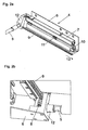
- Fig. 2a shows a perspective view of a rail system 4 to be fixed to the furniture body 2 carcass rail 6 and the sliding drawer rail 7.
- a middle rail 10 is slidably mounted in a known manner, so as a full extension of the drawer 3 relative to the furniture body 2 to allow.
- a synchronization device 11 is provided with a rotatably mounted on the center rail 10 pinion, which can control the movable rails 7, 10 relative to each other according to a differential extract, so that the drawer rail 7 at about twice the speed than the Middle rail 10 moves.
- a bearing block 12 is firmly connected. In this bearing block 12 is in Fig.
- the rack 9 extends in the withdrawal 13 of the drawer 3 and extends substantially over the entire length of a rail 6, 7, 10, in the present case over the entire length of the carcass rail 6. Of course, it would also be possible that the rack 9 only over part of the length of a rail. 6 , 7, 10 extends.
- the drawer rail 7 is moved together with the bearing block 12 arranged thereon and along with the synchronization rod 5 along the rack 9 to the front, wherein the gear 8 runs along the rack 9.
- the movement of the gears 8 of two opposite to a furniture body 2 rail systems 4 can be synchronized by the synchronization rod 5.
- Fig. 2b shows only schematically the mechanical reversal, namely, that the bearing block 12 with the gear 8 on the carcass rail 6 (or alternatively on the furniture body 2) and that the rack 9 is mounted on the drawer rail 7 (or on the drawer 3).
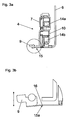
- Fig. 3a shows a vertical section of the rail system 4 with the stationary carcass rail 6, the movable relative to the middle rail 10 and the drawer rail 7. Between the rails 6, 7, 10 are movable carriages 14a, 14b mounted with load-transmitting rolling elements.
- the rack 9 is connected via a resilient region 15 with the fixed part of the carcass rail 6.
- Fig. 3b is the in Fig. 3a circled area shown in an enlarged view.
- the resilient region 15 is realized in the illustrated embodiment by a film joint 15a, ie by a longitudinal direction of the rail 6, 7, 10 extending local weakening of the rail 6 in the form of a groove 16, whereby a partial flexibility of the rack 9 is brought about in the height direction.
- the height-movable mounting of the rack 9 can also be brought about by a bending joint, so that the rack 9 is mounted limited vertically movable along the double arrow shown.
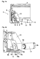
- Fig. 4a shows the drawer 3 connected to the rail system 4 in a view from behind.
- the bearing block 12 is fixedly connected to the drawer rail 7, wherein the gear 8 engages the rack 9 connected to the rack rail 6.
- Rail systems 4 is synchronized by the synchronization rod 5 relative to each other.
- the synchronization rod 5 is formed in two parts in the illustrated embodiment and comprises the two shaft parts 5a and 5b, which are connected via a hinge 17 with each other. Through the joint 17 of the synchronization rod 5 installation tolerances, height errors and any angular misalignment of two opposing rail systems 4 can be compensated.
- the hinge 17 is designed such that a rotational movement of the two shaft parts 5a, 5b relative to each other is possible.
- Fig. 4b shows the located in the closed position rail system 4 in a perspective view from behind.
- the rail system 4 has a limiting device 18 which limits the immersion depth of the gear 8 relative to the rack 9 such that the teeth 8a of the gear 8 only partially engage in the corresponding tooth gaps 9a of the rack 9.
- the limiting device 18 comprises a - preferably formed as a friction wheel - impeller 18 a, which is rotatably mounted coaxially with the gear 8.
- the diameter of the impeller 18a is less than that of the gear 8.
- Recognizable is a - preferably elastically yielding - part 18b, which may extend substantially over the entire length of the rack 9.
- the impeller 18a travels on or along a running surface of the plastic-made member 18b, whereby the teeth 8a of the gear 8 can not fully enter the tooth spaces 9a of the rack 9. In this way, jamming between gear 8 and rack 9 can be effectively prevented, whereby the risk of jamming of the drawer 3 is prevented in normal use.
- the limiting device 18 also includes a rack 18c engaging under the rack 9, by means of which the lifting height of the toothed wheel 8 relative to the rack 9 can be limited.
- the web 18 c is part of the bearing block 12 in the illustrated embodiment and can be moved along the fixed rack 9 when moving the drawer 3.
- the plastic part 18b acts as a kind of cushion between the gear 8 and the rack 9, whereby the gear 8 is guided without play and quiet.
- Fig. 5a shows an exploded view of a rail system 4, wherein the rack 9 is formed on a substantially L-shaped adapter 19.
- the adapter 19 comprises two legs which are substantially at right angles to one another 19a and 19b, wherein the rack 9 is mounted on the leg 19b.
- the adapter 19 is in particular also suitable for equipping a commercially available pull-out guide for drawers 3 - consisting of a carcass rail 6 and at least one shutter rail 7 which can be displaced relative thereto - already ex works or subsequently with a toothed rack 9.
- the adapter 19 may be made of plastic or metal.
- the adapter has attachment points 21a and 21b, which are aligned with the attachment points 6a, 6b of the carcass rail 6.
- attachment points 21a, 21b of the adapter 19 are merely possible embodiments, in particular, a snap connection between the adapter 19 and the rail system 4 may be provided.
- Fig. 5b shows the attached to the furniture body 2 carcass rail 6 according to Fig. 5a .
- the leg 19a of the adapter 19 is screwed between the carcass rail 6 and the furniture body 2.
- the lower leg 19b of the adapter 19 is resilient, so that the rack mounted thereon 9 is mounted limited vertically movable so as to prevent jamming between the gear 8 and rack 9 during the movement path of the drawer 2.
- Fig. 6a shows an embodiment of a synchronization rod 5, which is provided for the synchronization of two opposite to a furniture body 2 rail systems 4.
- the synchronization rod 5 is formed in two parts and comprises two shaft parts 5a and 5b, which are connected to each other via a hinge 17.
- the joint 17 is a radial movement possibility of the two shaft parts 5a and 5b relative to each other possible.
- the joint 17 may be formed as a universal joint, in particular as a cardan joint or as a ball joint. In this way, the relative offset of two opposite to a furniture body 2 rail systems 4 can be compensated.
- Fig. 6b shows the synchronization rod 5 with the two shaft parts 5a, 5b according to Fig. 6a in a sectional view. Visible is the gearwheel head 20 arranged on the shaft part 5a, which engages in a corresponding toothing of the joint 17.
Landscapes
- Drawers Of Furniture (AREA)
- Transmission Devices (AREA)
Description
- Die vorliegende Erfindung bezieht sich auf ein Schienensystem für Schubladen, mit einer an einem Möbelkorpus zu befestigenden Korpusschiene und wenigstens einer relativ zur Korpusschiene bewegbaren Ladenschiene, und mit wenigstens einer Zahnstangen-Ritzel-Anordnung.
- Im Weiteren betrifft die Erfindung eine Anordnung von zwei Schienensystemen der zu beschreibenden Art, welche an gegenüberliegenden Seitenwänden eines Möbels zu montieren sind und die zur Übertragung einer synchronen Bewegung über eine Synchronisationsstange miteinander verbunden sind.
- Derartige Schienensysteme werden üblicherweise dazu verwendet, die Bewegung zweier an einem Möbel gegenüberliegender Schubladenausziehführungen durch eine Zahnstangen-Ritzel-Anordnung relativ zueinander zu synchronisieren. Auf diese Weise ist eine präzise Parallelführung eines ausziehbaren Möbelteiles - insbesondere der Schublade - möglich. Diese Parallelführung relativ zu einem Möbelkorpus ist insbesondere dann vorteilhaft, wenn sehr schmale oder sehr breite Schubladen bewegt werden sollen, wobei durch die Parallelführung ein seitliches Verkanten der Schublade weitgehend verhindert wird. Die Bewegung der gegenüberliegenden Schienensysteme wird häufig über eine quer zur Ausziehrichtung verlaufende Synchronisationsstange synchronisiert. An beiden Endbereichen der Synchronisationsstange sind Zahnräder gelagert, welche jeweils in die Zahnstangen der zu synchronisierenden Schienensysteme eingreifen. Aus der
EP 1 036 526 B1 der Anmelderin ist eine solche Parallelführung mit einer Zahnstangen-Ritzel-Anordnung bekannt geworden. Bei bekannten Schienensystemen kann mitunter das Problem auftreten, dass die formschlüssige Verbindung zwischen der Zahnstange und dem Zahnrad zu einem Verklemmen des Schienensystems und damit zu einem unerwünschten Blockieren der Schublade im normalen Gebrauch führen kann. - Aufgabe der vorliegenden Erfindung ist es, ein Schienensystem der eingangs erwähnten Gattung mit verbesserten Laufeigenschaften vorzuschlagen.
- Dies wird erfindungsgemäß durch die Merkmale des Patentanspruchs 1 gelöst. Weitere vorteilhafte Ausgestaltungen der Erfindung sind in den Unteransprüchen angegeben.
- Somit ist also eine Begrenzungsvorrichtung vorgesehen, welche die Eintauchtiefe des Zahnrades relativ zur Zahnstange derart begrenzt, dass die Zähne des Zahnrades nur teilweise in die entsprechenden Zahnlücken der Zahnstange eingreifen.
- Grundsätzlich ist bei einer Zahnstangen-Zahnrad-Anordnung darauf zu achten, dass die Eingriffstiefe der Zähne in die Zahnlücken der Zahnstange weder zu tief noch zu flach ist. Durch die vorgeschlagene Begrenzungseinrichtung ist es möglich, dass die Eingriffstiefe des Zahnrades relativ zur Zahnstange einen bestimmten Wert aufweist oder innerhalb eines vorgegebenen Bereiches liegt. Auf diese Weise wird die Gefahr eines Verklemmens zwischen Zahnrad und Zahnstange (und damit ein Verklemmen des Schubladenschienensystems) weitgehend reduziert. Darüber hinaus ist auf diese Weise auch eine geräuscharme Verschiebebewegung des Schienensystems möglich.
- Erfindungsgemäß weist die Begrenzungsvorrichtung ein Laufrad auf, welches an einer Lauffläche eines in Längsrichtung des Schienensystems angeordneten Teiles abläuft. Dieser Teil ist als elastisch nachgiebiger Kunststoffteil hergestellt, welcher als Polster zwischen der Zahnstange und dem Laufrad wirkt. In konstruktiv einfacher Weise ist das Laufrad koaxial zur Drehachse des Zahnrades gelagert.
- Gemäß einer Weiterbildung der Erfindung kann vorgesehen sein, dass die Begrenzungseinrichtung wenigstens einen die Zahnstange untergreifenden Steg aufweist, durch den die Abhebehöhe des Zahnrades relativ zur Zahnstange begrenzbar ist. Mit anderen Worten wird dabei stets ein ausreichend tiefer Eingriff der Zähne des Zahnrades in die Zahnstange sichergestellt, ohne dass dabei das Zahnrad von der Zahnstange abhebt und der Formschluss zwischen Zahnrad und Zahnstange aufgehoben wird.
- Bei einem Ausführungsbeispiel der Erfindung kann vorgesehen sein, dass die Zahnstange gegenüber der Schiene, an der sie befestigt ist, begrenzt höhenbeweglich gelagert ist.
- Durch eine begrenzt höhenbewegliche Lagerung der Zahnstange kann beim Herausziehen und beim Einschieben der Schublade ein Verkanten zwischen Zahnrad und Zahnstange weitgehend vermieden werden, da die in Höhenrichtung federnd gelagerte Zahnstange dem Zahnrad in allfälligen Klemmsituationen nachgeben kann, wobei jedoch der Formschluss zwischen dem Zahnrad und der Zahnstange aufrecht erhalten wird. Die Zahnstange kann also elastisch zum Zahnrad hin vorbelastet sein, entweder durch Eigenelastizität oder durch die Wirkung einer Feder.
- Gemäß einem Ausführungsbeispiel der Erfindung kann vorgesehen sein, dass die Zahnstange über einen federnd nachgiebigen Abschnitt begrenzt höhenbeweglich gelagert ist. Der federnd nachgiebige Bereich ist derart ausgebildet, dass die Zahnstange nach einem vertikalen Ausweichen selbsttätig wieder in die ursprüngliche Ausgangslage zurückbewegt wird.
- Gemäß einem Ausführungsbeispiel der Erfindung kann vorgesehen sein, dass die Zahnstange über ein Filmgelenk mit einer der Schienen verbunden ist. Eine solche Gelenkverbindung zwischen der Zahnstange und dem stationären oder höhenunbeweglichen Teil der Schiene kann durch eine dünnwandige Verbindung (z.B. durch eine in Schienenlängsrichtung verlaufende Nut) herbeigeführt werden. Ebenso ist ein Biegegelenk vorteilhaft einsetzbar, durch welches die Zahnstange um eine Längsachse schwenkbar ist.
- Bei einer möglichen Weiterbildung der Erfindung kann vorgesehen sein, dass die Zahnstange an einem Adapter angeordnet oder ausgebildet ist, wobei der Adapter über wenigstens eine Befestigungsstelle mit einer der Schienen verbunden oder lösbar verbindbar ist. Hierbei kann es zweckmäßig sein, wenn der Adapter im Wesentlichen als L-Profil ausgebildet ist, wobei in Montagelage ein Schenkel des L-Profils an einem Vertikalsteg der Korpusschiene und ein anderer Schenkel des L-Profils an einem Horizontalsteg der Korpusschiene anliegt. Eine einfache Befestigung kann dahingehend erfolgen, indem der Adapter gleichzeitig mit der Montage des Schienensystems am Möbelkorpus befestigt wird.
- Angemerkt sei, dass wenigstens ein Zahnrad vorgesehen ist, welches in die Zahnstange des Schienensystems eingreift. Das in die Zahnstange eingreifende Zahnrad kann als Parallelführungszahnrad mit der Synchronisationsstange mittelbar oder unmittelbar gekoppelt sein. Insbesondere kann eine drehfeste Verbindung zwischen dem Zahnrad und der Synchronisationsstange vorgesehen werden.
- Gemäß einer ersten Ausführungsform ist vorgesehen, dass die Zahnstange an der Korpusschiene oder am Möbelkorpus und das Zahnrad an der Ladenschiene oder an der Schublade gelagert ist. Gemäß einer alternativen Ausführungsform kann vorgesehen sein, dass die Zahnstange an der Ladenschiene oder an der Schublade und dass das Zahnrad an der Korpusschiene oder am Möbelkorpus gelagert ist.
- Weitere Einzelheiten und Vorteile der vorliegenden Erfindung werden anhand der nachfolgenden Figurenbeschreibung erläutert. Dabei zeigt bzw. zeigen:
- Fig. 1
- eine perspektivische Darstellung eines Möbels mit Schubladen, welche über gegenüberliegende Schienensysteme relativ zu einem Möbelkorpus verfahrbar gelagert sind,
- Fig. 2a, 2b
- eine perspektivische Darstellung eines Schienensystems, wobei die zur Synchronisation der Bewegung der Schublade vorgesehene Zahnstange an der Korpusschiene angeordnet ist, sowie eine perspektivische Darstellung einer an der Schublade angeordneten Zahnstange,
- Fig. 3a, 3b
- eine Schnittdarstellung des Schienensystems, wobei die Zahnstange über ein Filmscharnier mit der Korpusschiene verbunden ist, sowie eine vergrößerte Detaildarstellung hierzu,
- Fig. 4a, 4b
- das Schienensystem in einer Ansicht von hinten sowie eine perspektivische Darstellung hierzu,
- Fig. 5a, 5b
- ein Ausführungsbeispiel der Erfindung mit einem die Zahnstange tragenden Adapter in einer perspektivischen Explosionsdarstellung sowie die Montagelage des Schienensystems in einer Schnittdarstellung,
- Fig. 6a, 6b
- ein mögliches Ausführungsbeispiel einer Synchronisationsstange, welche zum Synchronisieren einer Bewegung von zwei an einem Möbelkorpus gegenüberliegenden Schienensystemen vorgesehen ist, wobei die Synchronisationsstange ein Gelenk aufweist.
-
Fig. 1 zeigt eine perspektivische Darstellung eines Möbels 1 mit einem schrankförmigen Möbelkorpus 2, wobei Schubladen 3 über Schienensysteme 4 relativ zum Möbelkorpus 2 verfahrbar gelagert sind. Auf jeder Seite der Schublade 3 befindet sich ein Schienensystem 4, wobei die beiden Schienensysteme 4 an gegenüberliegenden Seitenwänden des Möbelkorpus 2 zu befestigen sind. Erkennbar ist eine quer zur Ausziehrichtung der Schublade 3 verlaufende Synchronisationsstange 5 in Form einer Torsionswelle. Durch die Synchronisationsstange 5 sind die Bewegungen der beiden Schienensysteme 4 relativ zueinander synchronisierbar, wodurch auch eine präzise Parallelführung der Schublade 3 relativ zum Möbelkorpus 2 herbeigeführt werden kann. Die beiden Schienensysteme 4 weisen jeweils eine am Möbelkorpus 2 zu befestigende Korpusschiene 6 sowie mindestens eine relativ zur Korpusschiene 6 verfahrbare Ladenschiene 7 auf. Der Zweck der Synchronisationsstange 5 liegt darin, die Bewegung der linken und rechten Ladenschiene 7 relativ zueinander zu synchronisieren, sodass die Schublade 3 ohne seitliches Verkanten aus dem Möbelkorpus 2 herausgezogen und in den Möbelkorpus 2 eingeschoben werden kann. Die Synchronisationsstange 5 weist an den Endbereichen wenigstens ein drehbar gelagertes Zahnrad 8 auf, welches mit einer Zahnstange 9 des Schienensystems 4 kämmt. Selbstverständlich ist es in mechanischer Umkehr auch möglich, die Zahnstange 9 an der Schublade 3 oder an der Ladenschiene 7 und das zugehörige Zahnrad 8 an der Korpusschiene 6 oder am Möbelkorpus 2 zu lagern. -
Fig. 2a zeigt eine perspektivische Darstellung eines Schienensystems 4 mit der am Möbelkorpus 2 zu befestigenden Korpusschiene 6 und der verschiebbaren Ladenschiene 7. Zwischen der Korpusschiene 6 und der Ladenschiene 7 ist in bekannter Weise eine Mittelschiene 10 verschiebbar gelagert, um so einen Vollauszug der Schublade 3 relativ zum Möbelkorpus 2 zu ermöglichen. Zur Synchronisation der Schienenbewegung eines einzelnen Schienensystems 4 ist eine Synchronisationsvorrichtung 11 mit einem an der Mittelschiene 10 drehbar gelagerten Ritzel vorgesehen, welche die bewegbaren Schienen 7, 10 relativ zueinander entsprechend einem Differentialauszug steuern kann, sodass sich die Ladenschiene 7 mit etwa der doppelten Geschwindigkeit als die Mittelschiene 10 bewegt. Mit der ausziehbaren Ladenschiene 7 ist ein Lagerbock 12 fest verbunden. In diesem Lagerbock 12 ist das inFig. 1 gezeigte Zahnrad 8 aufgenommen, welches in die Zahnstange 9 eingreift. Die Zahnstange 9 verläuft in Ausziehrichtung 13 der Schublade 3 und erstreckt sich im Wesentlichen über die gesamte Länge einer Schiene 6, 7, 10, im vorliegenden Fall über die gesamte Länge der Korpusschiene 6. Selbstverständlich wäre es auch möglich, dass sich die Zahnstange 9 auch nur über einen Teil der Länge einer Schiene 6, 7, 10 erstreckt. Beim Ausziehen der Schublade 3 in Ausziehrichtung 13 wird die Ladenschiene 7 zusammen mit dem daran angeordneten Lagerbock 12 und zusammen mit der Synchronisationsstange 5 entlang der Zahnstange 9 nach vorne bewegt, wobei auch das Zahnrad 8 entlang der Zahnstange 9 abläuft. Die Bewegung der Zahnräder 8 zweier an einem Möbelkorpus 2 gegenüberliegender Schienensysteme 4 ist durch die Synchronisationsstange 5 synchronisierbar. -
Fig. 2b zeigt nur schematisch die mechanische Umkehr, nämlich, dass der Lagerbock 12 mit dem Zahnrad 8 an der Korpusschiene 6 (oder alternativ am Möbelkorpus 2) und dass die Zahnstange 9 an der Ladenschiene 7 (oder auch an der Schublade 3) gelagert ist. -
Fig. 3a zeigt einen Vertikalschnitt des Schienensystems 4 mit der stationären Korpusschiene 6, der relativ dazu bewegbaren Mittelschiene 10 sowie mit der Ladenschiene 7. Zwischen den Schienen 6, 7, 10 sind verschiebbare Laufwagen 14a, 14b mit lastübertragenden Wälzkörpern gelagert. Im gezeigten Ausführungsbeispiel ist die Zahnstange 9 über einen federnden Bereich 15 mit dem feststehenden Teil der Korpusschiene 6 verbunden. InFig. 3b ist der inFig. 3a eingekreiste Bereich in einer vergrößerten Darstellung gezeigt. Der federnd nachgiebige Bereich 15 wird im gezeigten Ausführungsbeispiel durch ein Filmgelenk 15a realisiert, also durch eine in Längsrichtung der Schiene 6, 7, 10 verlaufende lokale Schwächung der Schiene 6 in Form einer Nut 16, wodurch eine Teilflexibilität der Zahnstange 9 in Höhenrichtung herbeigeführt wird. Auf diese Weise kann die Gefahr eines Verklemmens zwischen dem Zahnrad 8 und der Zahnstange 9 weitgehend reduziert werden. Die höhenbewegliche Lagerung der Zahnstange 9 kann auch über ein Biegegelenk herbeigeführt werden, sodass die Zahnstange 9 entlang des eingezeichneten Doppelpfeiles begrenzt höhenbeweglich gelagert ist. -
Fig. 4a zeigt die mit dem Schienensystem 4 verbundene Schublade 3 in einer Ansicht von hinten. Der Lagerbock 12 ist mit der Ladenschiene 7 fest verbunden, wobei das Zahnrad 8 in die mit der Korpusschiene 6 verbundene Zahnstange 9 eingreift. Die Drehbewegung der Zahnräder 8 zweier an einem Möbelkorpus 2 gegenüberliegender Schienensysteme 4 wird durch die Synchronisationsstange 5 relativ zueinander synchronisiert. Die Synchronisationsstange 5 ist im gezeigten Ausführungsbeispiel zweiteilig ausgebildet und umfasst die beiden Wellenteile 5a und 5b, welche über ein Gelenk 17 miteinander verbunden sind. Durch das Gelenk 17 der Synchronisationsstange 5 können Einbautoleranzen, Höhenfehler und ein allfälliger Winkelversatz zweier gegenüberliegender Schienensysteme 4 kompensiert werden. Das Gelenk 17 ist derart ausgebildet, dass eine rotatorische Bewegung der beiden Wellenteile 5a, 5b relativ zueinander möglich ist. -
Fig. 4b zeigt das in der Schließstellung befindliche Schienensystem 4 in einer perspektivischen Ansicht von hinten. Das Schienensystem 4 weist eine Begrenzungsvorrichtung 18 auf, welche die Eintauchtiefe des Zahnrades 8 relativ zur Zahnstange 9 derart begrenzt, dass die Zähne 8a des Zahnrades 8 nur teilweise in die entsprechenden Zahnlücken 9a der Zahnstange 9 eingreifen. Die Begrenzungsvorrichtung 18 umfasst ein - vorzugsweise als Reibrad ausgebildetes - Laufrad 18a, welches koaxial zum Zahnrad 8 drehbar gelagert ist. Der Durchmesser des Laufrades 18a ist geringer als jener des Zahnrades 8. Erkennbar ist ein - vorzugsweise elastisch nachgiebiger - Teil 18b, der sich im Wesentlichen über die gesamte Länge der Zahnstange 9 erstrecken kann. Das Laufrad 18a läuft an oder entlang einer Lauffläche des aus Kunststoff hergestellten Teiles 18b ab, wodurch die Zähne 8a des Zahnrades 8 nicht vollständig in die Zahnlücken 9a der Zahnstange 9 eintreten können. Auf diese Weise kann ein Verklemmen zwischen Zahnrad 8 und Zahnstange 9 wirkungsvoll verhindert werden, wodurch auch die Gefahr eines Verklemmens der Schublade 3 im normalen Gebrauch verhindert wird. Die Begrenzungsvorrichtung 18 umfasst auch einen die Zahnstange 9 untergreifenden Steg 18c, durch den die Abhebehöhe des Zahnrades 8 relativ zur Zahnstange 9 begrenzbar ist. Der Steg 18c ist im gezeigten Ausführungsbeispiel Teil des Lagerbockes 12 und kann beim Bewegen der Schublade 3 entlang der feststehenden Zahnstange 9 bewegt werden. Der Kunststoffteil 18b wirkt quasi als Polster zwischen dem Zahnrad 8 und der Zahnstange 9, wodurch das Zahnrad 8 spielfrei und geräuscharm geführt ist. -
Fig. 5a zeigt eine Explosionsdarstellung eines Schienensystems 4, wobei die Zahnstange 9 an einem im Wesentlichen L-förmigen Adapter 19 ausgebildet ist. Der Adapter 19 umfasst zwei im Wesentlichen rechtwinklig zueinander stehende Schenkel 19a und 19b, wobei die Zahnstange 9 am Schenkel 19b gelagert ist. Der Adapter 19 ist insbesondere auch dazu geeignet, eine handelsübliche Ausziehführung für Schubladen 3 - bestehend aus einer Korpusschiene 6 und wenigstens einer relativ dazu verschiebbaren Ladenschiene 7 - bereits ab Werk oder auch nachträglich mit einer Zahnstange 9 auszurüsten. Der Adapter 19 kann aus Kunststoff oder aus Metall hergestellt sein. Der Adapter weist Befestigungsstellen 21a und 21b auf, welche mit den Befestigungsstellen 6a, 6b der Korpusschiene 6 fluchten. Bei der Montage werden also Schrauben durch die Befestigungsstellen 6a, 6b der Korpusschiene 6 und durch die Befestigungsstellen 21a, 21b des Adapters 19 hindurchgeführt und mit dem Möbelkorpus 2 verschraubt. Die Befestigungsstellen 21a, 21b des Adapters 19 sind lediglich mögliche Ausgestaltungen, insbesondere kann auch eine Schnappverbindung zwischen dem Adapter 19 und dem Schienensystem 4 vorgesehen werden. -
Fig. 5b zeigt die am Möbelkorpus 2 befestigte Korpusschiene 6 gemäßFig. 5a . Bei der Montage wird der Schenkel 19a des Adapters 19 zwischen der Korpusschiene 6 und dem Möbelkorpus 2 verschraubt. Der untere Schenkel 19b des Adapters 19 ist federnd ausgebildet, sodass die darauf gelagerte Zahnstange 9 begrenzt höhenbeweglich gelagert ist, um so ein Verklemmen zwischen Zahnrad 8 und Zahnstange 9 während des Bewegungsweges der Schublade 2 zu verhindern. -
Fig. 6a zeigt ein Ausführungsbeispiel einer Synchronisationsstange 5, welche zur Synchronisation zweier an einem Möbelkorpus 2 gegenüberliegenden Schienensysteme 4 vorgesehen ist. Die Synchronisationsstange 5 ist zweiteilig ausgebildet und umfasst zwei Wellenteile 5a und 5b, welche über ein Gelenk 17 miteinander verbunden sind. Durch das Gelenk 17 ist eine radiale Bewegungsmöglichkeit der beiden Wellenteile 5a und 5b relativ zueinander möglich. Das Gelenk 17 kann als Wellengelenk, insbesondere als Kardangelenk oder als Kugelgelenk ausgebildet werden. Auf diese Weise kann der relative Versatz zweier an einem Möbelkorpus 2 gegenüberliegenden Schienensysteme 4 ausgeglichen werden.Fig. 6b zeigt die Synchronisationsstange 5 mit den beiden Wellenteilen 5a, 5b gemäßFig. 6a in einer Schnittdarstellung. Erkennbar ist der am Wellenteil 5a angeordnete Zahnradkopf 20, der in einer korrespondierenden Verzahnung des Gelenks 17 eingreift. - Die Erfindung beschränkt sich nicht auf die gezeigten Ausführungsbeispiele, sondern umfasst bzw. erstreckt sich auf alle technischen Äquivalente, die in die Reichweite der nachfolgenden Ansprüche fallen können. Auch sind die in der Beschreibung gewählten Lageangaben, wie z.B. oben, unten, seitlich usw. auf die unmittelbar beschriebene sowie dargestellte Figur bezogen und sind bei einer Lageänderung sinngemäß auf die neue Lage zu übertragen.
Claims (13)
- Schienensystem (4) für Schubladen (3), mit einer an einem Möbelkorpus (2) zu befestigenden Korpusschiene (6), einer relativ zur Korpusschiene (6) bewegbaren Ladenschiene (7), wenigstens einer Zahnstangen-Zahnrad-Anordnung (8, 9) und mit einer Begrenzungsvorrichtung (18), welche die Eintauchtiefe des Zahnrades (8) relativ zur Zahnstange (9) begrenzt, wobei die Zähne (8a) des Zahnrades (8) nur teilweise in die entsprechenden Zahnlücken (9a) der Zahnstange (9) eingreifen und wobei die Begrenzungsvorrichtung (18) ein Laufrad (18a) aufweist, welches an einer Lauffläche eines in Längsrichtung des Schienensystems (4) angeordneten Teiles (18b) abläuft, dadurch gekennzeichnet, dass das Laufrad (18a) an einem elastisch nachgiebigen Teil (18b) abläuft, welcher als Polster zwischen dem Zahnrad (8) und der Zahnstange (9) wirkt.
- Schienensystem nach Anspruch 1, dadurch gekennzeichnet, dass das Laufrad (18a) koaxial zur Drehachse des Zahnrades (8) gelagert ist.
- Schienensystem nach Anspruch 1 oder 2, dadurch gekennzeichnet, dass die Begrenzungseinrichtung (18) wenigstens einen die Zahnstange (9) untergreifenden Steg (18c) aufweist, durch den die Abhebehöhe des Zahnrades (8) relativ zur Zahnstange (9) begrenzbar ist.
- Schienensystem nach einem der Ansprüche 1 bis 3, dadurch gekennzeichnet, dass die Zahnstange (9) gegenüber der Schiene (6, 7, 10), an der sie befestigt ist, begrenzt höhenbeweglich gelagert ist.
- Schienensystem nach Anspruch 4, dadurch gekennzeichnet, dass die Zahnstange (9) über einen federnd nachgiebigen Abschnitt (15) begrenzt höhenbeweglich gelagert ist.
- Schienensystem nach Anspruch 4 oder 5, dadurch gekenntzeichnet, dass die Zahnstange (9) über ein Filmgelenk (15a) mit einer der Schienen (6, 7, 10) verbunden ist.
- Schienensystem nach einem der Ansprüche 1 bis 5, dadurch gekennzeichnet, dass die Zahnstange (9) an einem Adapter (19) angeordnet oder ausgebildet ist, wobei der Adapter (19) über wenigstens eine Befestigungsstelle (21a, 21b) mit einer der Schienen (6, 7, 10) verbunden oder lösbar verbindbar ist.
- Schienensystem nach Anspruch 7, dadurch gekennzeichnet, dass der Adapter (19) im Wesentlichen als L-Profil ausgebildet ist, wobei in Montagelage ein Schenkel (19a) des L-Profiles an einem Vertikalsteg der Korpusschiene (6) und ein anderer Schenkel (19b) des L-Profils an einem Horizontalsteg der Korpusschiene (6) anliegt.
- Schienensystem nach Anspruch 7 oder 8, dadurch gekennzeichnet, dass der Adapter (19) zur bestimmungsgemäßen Montage am Schienensystem (4) zwischen der Korpusschiene (6) und dem Möbelkorpus (2) verschraubbar ist.
- Schienensystem nach einem der Ansprüche 1 bis 9, dadurch gekennzeichnet, dass die Zahnstange (9) an der Korpusschiene (6) oder am Möbelkorpus (2) angeordnet ist und dass das Zahnrad (8) an der Ladenschiene (7) oder an der Schublade (3) gelagert ist.
- Schienensystem nach einem der Ansprüche 1 bis 9, dadurch gekennzeichnet, dass die Zahnstange (9) an der Ladenschiene (7) oder an der Schublade (3) angeordnet ist und dass das Zahnrad (8) an der Korpusschiene (6) oder am Möbelkorpus (2) gelagert ist.
- Anordnung mit zwei Schienensystemen nach einem der Ansprüche 1 bis 11, dadurch gekennzeichnet, dass die zwei Schienensysteme (4) an gegenüberliegenden Seitenwänden eines Möbels (1) zu befestigen sind und die Schienensysteme (4) zur Übertragung einer synchronen Bewegung über eine Synchronisationsstange (5) miteinander verbunden oder miteinander verbindbar sind, wobei jeweils wenigstens ein Zahnrad (8) in jeweils einer Zahnstange (9) des Schienensystems (4) eingreift.
- Möbel mit einer Anordnung nach Anspruch 12.
Applications Claiming Priority (2)
| Application Number | Priority Date | Filing Date | Title |
|---|---|---|---|
| ATA2027/2009A AT509256B1 (de) | 2009-12-23 | 2009-12-23 | Schienensystem für schubladen |
| PCT/AT2010/000460 WO2011075753A1 (de) | 2009-12-23 | 2010-11-25 | Schienensystem für schubladen |
Publications (2)
| Publication Number | Publication Date |
|---|---|
| EP2515711A1 EP2515711A1 (de) | 2012-10-31 |
| EP2515711B1 true EP2515711B1 (de) | 2014-01-08 |
Family
ID=43608240
Family Applications (1)
| Application Number | Title | Priority Date | Filing Date |
|---|---|---|---|
| EP10797983.3A Active EP2515711B1 (de) | 2009-12-23 | 2010-11-25 | Schienensystem für schubladen |
Country Status (8)
| Country | Link |
|---|---|
| US (1) | US8668287B2 (de) |
| EP (1) | EP2515711B1 (de) |
| JP (1) | JP5905395B2 (de) |
| CN (1) | CN102665488B (de) |
| AT (1) | AT509256B1 (de) |
| ES (1) | ES2456893T3 (de) |
| MY (1) | MY155422A (de) |
| WO (1) | WO2011075753A1 (de) |
Families Citing this family (16)
| Publication number | Priority date | Publication date | Assignee | Title |
|---|---|---|---|---|
| AT511045A1 (de) * | 2011-01-28 | 2012-08-15 | Blum Gmbh Julius | Möbelteil mit einer drehmomentübertragenden welle |
| AT512382B1 (de) * | 2011-12-27 | 2016-05-15 | Blum Gmbh Julius | Synchronisationsvorrichtung für eine schublade |
| DE202012002378U1 (de) * | 2012-03-08 | 2013-06-10 | Grass Gmbh | Führungseinrichtung zur Führung eines relativ zu einem Möbelkorpus bewegbaren Möbelteils |
| US9016813B2 (en) * | 2013-01-18 | 2015-04-28 | Electrolux Home Products, Inc. | Floating time bar |
| US9016812B2 (en) * | 2013-06-04 | 2015-04-28 | General Electric Company | Translatable support mechanism |
| CN103584527B (zh) * | 2013-10-24 | 2016-04-06 | 伍志勇 | 一种抽屉滑轨系统的同步装置 |
| CN103919375B (zh) * | 2014-04-25 | 2016-03-02 | 无锡海达尔精密滑轨有限公司 | 三段式隐藏滑轨机构 |
| AT14687U1 (de) * | 2014-06-16 | 2016-04-15 | Blum Gmbh Julius | Antriebsvorrichtung für ein bewegbares Möbelteil |
| US9763518B2 (en) * | 2014-08-29 | 2017-09-19 | Cisco Technology, Inc. | Systems and methods for damping a storage system |
| US9982937B2 (en) | 2015-08-20 | 2018-05-29 | Dometic Sweden Ab | Appliance with geared drawer assembly |
| CN106037297B (zh) * | 2016-06-24 | 2018-06-05 | 无锡海达尔精密滑轨股份有限公司 | 具有消音回弹功能的同步抽屉滑轨系统 |
| TWI629027B (zh) * | 2017-03-20 | 2018-07-11 | 川湖科技股份有限公司 | 用於滑軌總成的同步系統 |
| DE102017108453A1 (de) | 2017-04-20 | 2018-10-25 | Paul Hettich Gmbh & Co. Kg | Möbel |
| CN107087910A (zh) * | 2017-07-03 | 2017-08-25 | 苏州市晨彩纺织研发有限公司 | 一种纺织用线筒存放架 |
| AT520817B1 (de) * | 2018-02-01 | 2019-08-15 | Blum Gmbh Julius | Anordnung aus Ausziehführung, Schienen-Synchronisierungsvorrichtung und Mitnehmer |
| RU194027U1 (ru) * | 2019-08-05 | 2019-11-25 | Общество с ограниченной ответственностью "ТОРГОВЫЙ ДОМ КОМКОР" | Синхронизатор выдвижного мебельного механизма |
Family Cites Families (31)
| Publication number | Priority date | Publication date | Assignee | Title |
|---|---|---|---|---|
| US3323853A (en) * | 1965-12-06 | 1967-06-06 | Art Metal Inc | Filing cabinet drawer motion control means |
| US3794401A (en) * | 1971-10-20 | 1974-02-26 | Wright Barry Corp | Door guide |
| AT386938B (de) * | 1983-05-03 | 1988-11-10 | Blum Gmbh Julius | Ausziehfuehrungsgarnitur fuer schubladen od.dgl. |
| JP2840124B2 (ja) * | 1990-08-28 | 1998-12-24 | 松下電工株式会社 | 移動収納庫の走行装置 |
| AT398888B (de) * | 1992-02-05 | 1995-02-27 | Fulterer Gmbh | Schubladenauszug |
| DE4220527C2 (de) * | 1992-06-23 | 1994-09-29 | Scharf Gmbh Maschf | Transporteinrichtung für untertägige Strecken |
| EP0718574A1 (de) * | 1994-12-19 | 1996-06-26 | Bosch-Siemens HausgerÀ¤te GmbH | Kältegerät |
| DE19858387A1 (de) | 1998-12-17 | 2000-06-21 | Bsh Bosch Siemens Hausgeraete | Kältegerät |
| ATE302558T1 (de) * | 1999-03-17 | 2005-09-15 | Blum Gmbh Julius | Vorrichtung zur stabilisierung des laufverhaltens einer in einem m-belkorpus verfahrbaren schublade |
| DE50102368D1 (de) * | 2000-01-14 | 2004-07-01 | Blum Gmbh Julius | Ausziehführungsgarnitur für Schubladen |
| US20050231083A1 (en) * | 2004-04-15 | 2005-10-20 | Garcie Kent C Jr | Undermount drawer slide |
| CA2530225C (en) * | 2004-12-15 | 2012-07-10 | Compx International Inc. | Low profile baseframe with vertical ballbearing slides |
| WO2007007950A1 (en) * | 2005-07-12 | 2007-01-18 | Lg Electronics Inc. | Rail assembly for drawer-type refrigerator |
| CN2894433Y (zh) * | 2005-10-25 | 2007-05-02 | 宋满英 | 一种滑轨缓冲装置 |
| DE202005018514U1 (de) * | 2005-11-26 | 2007-04-12 | Hettich Paul Gmbh & Co Kg | Schublade |
| JP3917169B1 (ja) * | 2006-08-28 | 2007-05-23 | 株式会社Inax | キッチンキャビネット |
| KR100790543B1 (ko) * | 2006-10-25 | 2008-01-02 | 엘지전자 주식회사 | 바스켓출납용 레일어셈블리 |
| WO2008051004A1 (en) * | 2006-10-25 | 2008-05-02 | Lg Electronics Inc. | Basket assembly and basket carrier for refrigerator |
| CN201073112Y (zh) * | 2007-06-13 | 2008-06-18 | 佳饰美企业有限公司 | 钢珠滑轨的自动关闭缓冲装置 |
| KR100895139B1 (ko) * | 2007-07-27 | 2009-05-04 | 엘지전자 주식회사 | 냉장고 |
| US7594707B2 (en) * | 2007-08-15 | 2009-09-29 | Whirlpool Corporation | Snap-in bearing rack and pinion system |
| MX2008005013A (es) * | 2008-04-17 | 2009-10-19 | Mabe Sa De Cv | Viga soporte para cajones en gabinetes. |
| US7997667B2 (en) * | 2008-06-09 | 2011-08-16 | Whirlpool Corporation | Rack and pinion refrigerator storage system |
| US8894602B2 (en) * | 2010-09-17 | 2014-11-25 | Johnson & Johnson Vision Care, Inc. | Punctal plugs with directional release |
| DE202008015848U1 (de) * | 2008-11-29 | 2010-04-15 | Paul Hettich Gmbh & Co. Kg | Synchronführung eines Schubelementes |
| TW201039777A (en) * | 2009-05-05 | 2010-11-16 | Zong-Yao Chen | Drawing stabilization structure of cupboard-drawing bearing member |
| DE202009016105U1 (de) * | 2009-07-06 | 2010-12-02 | Paul Hettich Gmbh & Co. Kg | Synchronführung eine Schubelements und Möbel |
| KR20110024883A (ko) * | 2009-09-03 | 2011-03-09 | 삼성전자주식회사 | 도어자동개폐장치 및 이를 구비한 냉장고 |
| AT509257B1 (de) * | 2009-12-23 | 2013-09-15 | Blum Gmbh Julius | Schienensystem für schubladen |
| US8360539B2 (en) * | 2010-02-26 | 2013-01-29 | Electrolux Home Products, Inc. | Drawer assembly |
| US8408663B2 (en) * | 2010-11-22 | 2013-04-02 | General Electric Company | Consumer appliance drawer with improved anti-racking system |
-
2009
- 2009-12-23 AT ATA2027/2009A patent/AT509256B1/de not_active IP Right Cessation
-
2010
- 2010-11-25 EP EP10797983.3A patent/EP2515711B1/de active Active
- 2010-11-25 ES ES10797983.3T patent/ES2456893T3/es active Active
- 2010-11-25 CN CN201080058040.1A patent/CN102665488B/zh active Active
- 2010-11-25 WO PCT/AT2010/000460 patent/WO2011075753A1/de not_active Ceased
- 2010-11-25 MY MYPI2012002328A patent/MY155422A/en unknown
- 2010-11-25 JP JP2012545007A patent/JP5905395B2/ja active Active
-
2012
- 2012-06-08 US US13/491,973 patent/US8668287B2/en active Active
Also Published As
| Publication number | Publication date |
|---|---|
| JP2013514843A (ja) | 2013-05-02 |
| CN102665488A (zh) | 2012-09-12 |
| CN102665488B (zh) | 2014-04-30 |
| MY155422A (en) | 2015-10-15 |
| WO2011075753A1 (de) | 2011-06-30 |
| EP2515711A1 (de) | 2012-10-31 |
| AT509256A1 (de) | 2011-07-15 |
| JP5905395B2 (ja) | 2016-04-20 |
| US8668287B2 (en) | 2014-03-11 |
| US20120243810A1 (en) | 2012-09-27 |
| ES2456893T3 (es) | 2014-04-23 |
| AT509256B1 (de) | 2013-06-15 |
Similar Documents
| Publication | Publication Date | Title |
|---|---|---|
| EP2515710B1 (de) | Schienensystem für schubladen | |
| AT509256B1 (de) | Schienensystem für schubladen | |
| AT510361B1 (de) | Ausziehführung für schubladen | |
| EP2770876B1 (de) | Synchronisierte verriegelung für ein bewegbares möbelteil | |
| EP2440088B1 (de) | Ausziehführung für schubladen | |
| AT508544B1 (de) | Kupplungsvorrichtung zum lösbaren verbinden einer schublade mit einer bewegbaren schiene | |
| EP2916688B1 (de) | Schubladenausziehführung | |
| EP2209400B1 (de) | Tragekonstruktion für wenigstens einen möbelantrieb | |
| EP2992781B1 (de) | Ausziehführung | |
| WO2015192153A1 (de) | Antriebsvorrichtung für ein bewegbares möbelteil | |
| EP1358819A1 (de) | Schubladenführung | |
| EP2992780B1 (de) | Ausziehführung | |
| EP1820422B1 (de) | Ausziehführung für ein aus einem Möbelkorpus ausziehbares Möbelteil | |
| EP1951088B1 (de) | Schublade | |
| WO2006114179A1 (de) | Möbel mit synchronisiert geführtem auszug | |
| EP2636340B1 (de) | Führungseinrichtung zur Führung eines relativ zu einem Möbelkorpus bewegbaren Möbelteils | |
| EP3498131B1 (de) | Ausziehführung | |
| AT11052U1 (de) | Ausziehführung für schubladen | |
| EP1649782B1 (de) | Ausziehführung | |
| EP0528218B1 (de) | Mit einer Dreh-Schiebetür verschliessbares Möbelstück, insbesondere Schrank | |
| DE3801403C2 (de) | Verstelleinrichtung zur Neigungs- und/oder Höhenverstellung einer Arbeits- oder Tischplate eines Möbels | |
| EP4384047B1 (de) | Einrichtung zur seitenführung des oberen endes eines ausziehbaren möbelteils |
Legal Events
| Date | Code | Title | Description |
|---|---|---|---|
| PUAI | Public reference made under article 153(3) epc to a published international application that has entered the european phase |
Free format text: ORIGINAL CODE: 0009012 |
|
| 17P | Request for examination filed |
Effective date: 20120514 |
|
| AK | Designated contracting states |
Kind code of ref document: A1 Designated state(s): AL AT BE BG CH CY CZ DE DK EE ES FI FR GB GR HR HU IE IS IT LI LT LU LV MC MK MT NL NO PL PT RO RS SE SI SK SM TR |
|
| DAX | Request for extension of the european patent (deleted) | ||
| REG | Reference to a national code |
Ref country code: DE Ref legal event code: R079 Ref document number: 502010005937 Country of ref document: DE Free format text: PREVIOUS MAIN CLASS: A47B0088040000 Ipc: A47B0088080000 |
|
| RIC1 | Information provided on ipc code assigned before grant |
Ipc: A47B 88/08 20060101AFI20130521BHEP |
|
| GRAP | Despatch of communication of intention to grant a patent |
Free format text: ORIGINAL CODE: EPIDOSNIGR1 |
|
| INTG | Intention to grant announced |
Effective date: 20130930 |
|
| RIN1 | Information on inventor provided before grant (corrected) |
Inventor name: SCHWARTZMANN, GUENTER |
|
| GRAS | Grant fee paid |
Free format text: ORIGINAL CODE: EPIDOSNIGR3 |
|
| GRAA | (expected) grant |
Free format text: ORIGINAL CODE: 0009210 |
|
| AK | Designated contracting states |
Kind code of ref document: B1 Designated state(s): AL AT BE BG CH CY CZ DE DK EE ES FI FR GB GR HR HU IE IS IT LI LT LU LV MC MK MT NL NO PL PT RO RS SE SI SK SM TR |
|
| REG | Reference to a national code |
Ref country code: GB Ref legal event code: FG4D Free format text: NOT ENGLISH |
|
| REG | Reference to a national code |
Ref country code: CH Ref legal event code: EP |
|
| REG | Reference to a national code |
Ref country code: IE Ref legal event code: FG4D Free format text: LANGUAGE OF EP DOCUMENT: GERMAN |
|
| REG | Reference to a national code |
Ref country code: AT Ref legal event code: REF Ref document number: 648109 Country of ref document: AT Kind code of ref document: T Effective date: 20140215 |
|
| REG | Reference to a national code |
Ref country code: DE Ref legal event code: R096 Ref document number: 502010005937 Country of ref document: DE Effective date: 20140220 |
|
| REG | Reference to a national code |
Ref country code: ES Ref legal event code: FG2A Ref document number: 2456893 Country of ref document: ES Kind code of ref document: T3 Effective date: 20140423 |
|
| REG | Reference to a national code |
Ref country code: NL Ref legal event code: VDEP Effective date: 20140108 |
|
| RIN2 | Information on inventor provided after grant (corrected) |
Inventor name: SCHWARTZMANN, GUENTER Inventor name: VIOLAND, WILFRIED |
|
| REG | Reference to a national code |
Ref country code: LT Ref legal event code: MG4D |
|
| PG25 | Lapsed in a contracting state [announced via postgrant information from national office to epo] |
Ref country code: IS Free format text: LAPSE BECAUSE OF FAILURE TO SUBMIT A TRANSLATION OF THE DESCRIPTION OR TO PAY THE FEE WITHIN THE PRESCRIBED TIME-LIMIT Effective date: 20140508 Ref country code: LT Free format text: LAPSE BECAUSE OF FAILURE TO SUBMIT A TRANSLATION OF THE DESCRIPTION OR TO PAY THE FEE WITHIN THE PRESCRIBED TIME-LIMIT Effective date: 20140108 Ref country code: NO Free format text: LAPSE BECAUSE OF FAILURE TO SUBMIT A TRANSLATION OF THE DESCRIPTION OR TO PAY THE FEE WITHIN THE PRESCRIBED TIME-LIMIT Effective date: 20140408 |
|
| PG25 | Lapsed in a contracting state [announced via postgrant information from national office to epo] |
Ref country code: CY Free format text: LAPSE BECAUSE OF FAILURE TO SUBMIT A TRANSLATION OF THE DESCRIPTION OR TO PAY THE FEE WITHIN THE PRESCRIBED TIME-LIMIT Effective date: 20140108 Ref country code: PT Free format text: LAPSE BECAUSE OF FAILURE TO SUBMIT A TRANSLATION OF THE DESCRIPTION OR TO PAY THE FEE WITHIN THE PRESCRIBED TIME-LIMIT Effective date: 20140508 Ref country code: SE Free format text: LAPSE BECAUSE OF FAILURE TO SUBMIT A TRANSLATION OF THE DESCRIPTION OR TO PAY THE FEE WITHIN THE PRESCRIBED TIME-LIMIT Effective date: 20140108 Ref country code: FI Free format text: LAPSE BECAUSE OF FAILURE TO SUBMIT A TRANSLATION OF THE DESCRIPTION OR TO PAY THE FEE WITHIN THE PRESCRIBED TIME-LIMIT Effective date: 20140108 Ref country code: NL Free format text: LAPSE BECAUSE OF FAILURE TO SUBMIT A TRANSLATION OF THE DESCRIPTION OR TO PAY THE FEE WITHIN THE PRESCRIBED TIME-LIMIT Effective date: 20140108 |
|
| PG25 | Lapsed in a contracting state [announced via postgrant information from national office to epo] |
Ref country code: HR Free format text: LAPSE BECAUSE OF FAILURE TO SUBMIT A TRANSLATION OF THE DESCRIPTION OR TO PAY THE FEE WITHIN THE PRESCRIBED TIME-LIMIT Effective date: 20140108 Ref country code: RS Free format text: LAPSE BECAUSE OF FAILURE TO SUBMIT A TRANSLATION OF THE DESCRIPTION OR TO PAY THE FEE WITHIN THE PRESCRIBED TIME-LIMIT Effective date: 20140108 Ref country code: LV Free format text: LAPSE BECAUSE OF FAILURE TO SUBMIT A TRANSLATION OF THE DESCRIPTION OR TO PAY THE FEE WITHIN THE PRESCRIBED TIME-LIMIT Effective date: 20140108 |
|
| REG | Reference to a national code |
Ref country code: DE Ref legal event code: R097 Ref document number: 502010005937 Country of ref document: DE |
|
| PG25 | Lapsed in a contracting state [announced via postgrant information from national office to epo] |
Ref country code: CZ Free format text: LAPSE BECAUSE OF FAILURE TO SUBMIT A TRANSLATION OF THE DESCRIPTION OR TO PAY THE FEE WITHIN THE PRESCRIBED TIME-LIMIT Effective date: 20140108 Ref country code: DK Free format text: LAPSE BECAUSE OF FAILURE TO SUBMIT A TRANSLATION OF THE DESCRIPTION OR TO PAY THE FEE WITHIN THE PRESCRIBED TIME-LIMIT Effective date: 20140108 Ref country code: RO Free format text: LAPSE BECAUSE OF FAILURE TO SUBMIT A TRANSLATION OF THE DESCRIPTION OR TO PAY THE FEE WITHIN THE PRESCRIBED TIME-LIMIT Effective date: 20140108 Ref country code: EE Free format text: LAPSE BECAUSE OF FAILURE TO SUBMIT A TRANSLATION OF THE DESCRIPTION OR TO PAY THE FEE WITHIN THE PRESCRIBED TIME-LIMIT Effective date: 20140108 |
|
| PLBE | No opposition filed within time limit |
Free format text: ORIGINAL CODE: 0009261 |
|
| STAA | Information on the status of an ep patent application or granted ep patent |
Free format text: STATUS: NO OPPOSITION FILED WITHIN TIME LIMIT |
|
| PG25 | Lapsed in a contracting state [announced via postgrant information from national office to epo] |
Ref country code: SK Free format text: LAPSE BECAUSE OF FAILURE TO SUBMIT A TRANSLATION OF THE DESCRIPTION OR TO PAY THE FEE WITHIN THE PRESCRIBED TIME-LIMIT Effective date: 20140108 Ref country code: PL Free format text: LAPSE BECAUSE OF FAILURE TO SUBMIT A TRANSLATION OF THE DESCRIPTION OR TO PAY THE FEE WITHIN THE PRESCRIBED TIME-LIMIT Effective date: 20140108 |
|
| 26N | No opposition filed |
Effective date: 20141009 |
|
| REG | Reference to a national code |
Ref country code: DE Ref legal event code: R097 Ref document number: 502010005937 Country of ref document: DE Effective date: 20141009 |
|
| PG25 | Lapsed in a contracting state [announced via postgrant information from national office to epo] |
Ref country code: SI Free format text: LAPSE BECAUSE OF FAILURE TO SUBMIT A TRANSLATION OF THE DESCRIPTION OR TO PAY THE FEE WITHIN THE PRESCRIBED TIME-LIMIT Effective date: 20140108 |
|
| PG25 | Lapsed in a contracting state [announced via postgrant information from national office to epo] |
Ref country code: MC Free format text: LAPSE BECAUSE OF FAILURE TO SUBMIT A TRANSLATION OF THE DESCRIPTION OR TO PAY THE FEE WITHIN THE PRESCRIBED TIME-LIMIT Effective date: 20140108 Ref country code: BE Free format text: LAPSE BECAUSE OF NON-PAYMENT OF DUE FEES Effective date: 20141130 Ref country code: LU Free format text: LAPSE BECAUSE OF FAILURE TO SUBMIT A TRANSLATION OF THE DESCRIPTION OR TO PAY THE FEE WITHIN THE PRESCRIBED TIME-LIMIT Effective date: 20141125 |
|
| REG | Reference to a national code |
Ref country code: CH Ref legal event code: PL |
|
| GBPC | Gb: european patent ceased through non-payment of renewal fee |
Effective date: 20141125 |
|
| PG25 | Lapsed in a contracting state [announced via postgrant information from national office to epo] |
Ref country code: LI Free format text: LAPSE BECAUSE OF NON-PAYMENT OF DUE FEES Effective date: 20141130 Ref country code: CH Free format text: LAPSE BECAUSE OF NON-PAYMENT OF DUE FEES Effective date: 20141130 |
|
| REG | Reference to a national code |
Ref country code: IE Ref legal event code: MM4A |
|
| REG | Reference to a national code |
Ref country code: FR Ref legal event code: ST Effective date: 20150731 |
|
| PG25 | Lapsed in a contracting state [announced via postgrant information from national office to epo] |
Ref country code: GB Free format text: LAPSE BECAUSE OF NON-PAYMENT OF DUE FEES Effective date: 20141125 Ref country code: IE Free format text: LAPSE BECAUSE OF NON-PAYMENT OF DUE FEES Effective date: 20141125 |
|
| PG25 | Lapsed in a contracting state [announced via postgrant information from national office to epo] |
Ref country code: FR Free format text: LAPSE BECAUSE OF NON-PAYMENT OF DUE FEES Effective date: 20141201 |
|
| PG25 | Lapsed in a contracting state [announced via postgrant information from national office to epo] |
Ref country code: SM Free format text: LAPSE BECAUSE OF FAILURE TO SUBMIT A TRANSLATION OF THE DESCRIPTION OR TO PAY THE FEE WITHIN THE PRESCRIBED TIME-LIMIT Effective date: 20140108 |
|
| PG25 | Lapsed in a contracting state [announced via postgrant information from national office to epo] |
Ref country code: BG Free format text: LAPSE BECAUSE OF FAILURE TO SUBMIT A TRANSLATION OF THE DESCRIPTION OR TO PAY THE FEE WITHIN THE PRESCRIBED TIME-LIMIT Effective date: 20140108 Ref country code: GR Free format text: LAPSE BECAUSE OF FAILURE TO SUBMIT A TRANSLATION OF THE DESCRIPTION OR TO PAY THE FEE WITHIN THE PRESCRIBED TIME-LIMIT Effective date: 20140409 |
|
| PG25 | Lapsed in a contracting state [announced via postgrant information from national office to epo] |
Ref country code: HU Free format text: LAPSE BECAUSE OF FAILURE TO SUBMIT A TRANSLATION OF THE DESCRIPTION OR TO PAY THE FEE WITHIN THE PRESCRIBED TIME-LIMIT; INVALID AB INITIO Effective date: 20101125 Ref country code: MT Free format text: LAPSE BECAUSE OF FAILURE TO SUBMIT A TRANSLATION OF THE DESCRIPTION OR TO PAY THE FEE WITHIN THE PRESCRIBED TIME-LIMIT Effective date: 20140108 |
|
| REG | Reference to a national code |
Ref country code: DE Ref legal event code: R079 Ref document number: 502010005937 Country of ref document: DE Free format text: PREVIOUS MAIN CLASS: A47B0088080000 Ipc: A47B0088490000 |
|
| PG25 | Lapsed in a contracting state [announced via postgrant information from national office to epo] |
Ref country code: MK Free format text: LAPSE BECAUSE OF FAILURE TO SUBMIT A TRANSLATION OF THE DESCRIPTION OR TO PAY THE FEE WITHIN THE PRESCRIBED TIME-LIMIT Effective date: 20140108 |
|
| PG25 | Lapsed in a contracting state [announced via postgrant information from national office to epo] |
Ref country code: AL Free format text: LAPSE BECAUSE OF FAILURE TO SUBMIT A TRANSLATION OF THE DESCRIPTION OR TO PAY THE FEE WITHIN THE PRESCRIBED TIME-LIMIT Effective date: 20140108 |
|
| P01 | Opt-out of the competence of the unified patent court (upc) registered |
Effective date: 20230523 |
|
| PGFP | Annual fee paid to national office [announced via postgrant information from national office to epo] |
Ref country code: DE Payment date: 20251126 Year of fee payment: 16 |
|
| PGFP | Annual fee paid to national office [announced via postgrant information from national office to epo] |
Ref country code: AT Payment date: 20251126 Year of fee payment: 16 |
|
| PGFP | Annual fee paid to national office [announced via postgrant information from national office to epo] |
Ref country code: IT Payment date: 20251121 Year of fee payment: 16 |
|
| PGFP | Annual fee paid to national office [announced via postgrant information from national office to epo] |
Ref country code: TR Payment date: 20251105 Year of fee payment: 16 |
|
| PGFP | Annual fee paid to national office [announced via postgrant information from national office to epo] |
Ref country code: ES Payment date: 20251209 Year of fee payment: 16 |