EP2511128A2 - Vehicle seat - Google Patents
Vehicle seat Download PDFInfo
- Publication number
- EP2511128A2 EP2511128A2 EP12001353A EP12001353A EP2511128A2 EP 2511128 A2 EP2511128 A2 EP 2511128A2 EP 12001353 A EP12001353 A EP 12001353A EP 12001353 A EP12001353 A EP 12001353A EP 2511128 A2 EP2511128 A2 EP 2511128A2
- Authority
- EP
- European Patent Office
- Prior art keywords
- air
- passage
- cushion pad
- vehicle
- permeable material
- Prior art date
- Legal status (The legal status is an assumption and is not a legal conclusion. Google has not performed a legal analysis and makes no representation as to the accuracy of the status listed.)
- Withdrawn
Links
Images


Classifications
-
- B—PERFORMING OPERATIONS; TRANSPORTING
- B60—VEHICLES IN GENERAL
- B60N—SEATS SPECIALLY ADAPTED FOR VEHICLES; VEHICLE PASSENGER ACCOMMODATION NOT OTHERWISE PROVIDED FOR
- B60N2/00—Seats specially adapted for vehicles; Arrangement or mounting of seats in vehicles
- B60N2/56—Heating or ventilating devices
- B60N2/5607—Heating or ventilating devices characterised by convection
- B60N2/5621—Heating or ventilating devices characterised by convection by air
- B60N2/5657—Heating or ventilating devices characterised by convection by air blown towards the seat surface
-
- B—PERFORMING OPERATIONS; TRANSPORTING
- B60—VEHICLES IN GENERAL
- B60N—SEATS SPECIALLY ADAPTED FOR VEHICLES; VEHICLE PASSENGER ACCOMMODATION NOT OTHERWISE PROVIDED FOR
- B60N2/00—Seats specially adapted for vehicles; Arrangement or mounting of seats in vehicles
- B60N2/56—Heating or ventilating devices
- B60N2/5607—Heating or ventilating devices characterised by convection
- B60N2/5621—Heating or ventilating devices characterised by convection by air
- B60N2/5642—Heating or ventilating devices characterised by convection by air with circulation of air through a layer inside the seat
Definitions
- the present invention generally relates to a seat for a vehicle. More specifically, the present invention relates to a vehicle seat having an air passage for introducing air to a cushion pad of the vehicle seat.
- Japanese Laid-Open Patent Publication No. H09-505499 discloses a seat cushion structure that has a cushion pad with a flow passage for introducing conditioned air to the cushion pad.
- air is blown into the cushion pad through the flow passage.
- the air exits from the cushion pad by an outlet on an outer surface side of the cushion pad.
- the air exits from the cushion pad and passes through a porous sheet that is covering the outlet. The air is then blow out from a sitting surface of an outer cover of the seat cushion structure.
- one object presented in the present disclosure is to provide a vehicle seat with which blown air can be satisfactorily delivered to a seated passenger and a comfortable sitting feeling can be obtained.
- one aspect of the present disclosure is to provide a vehicle seat that comprises a cushion pad, a breathable outer cover and an air permeable material layer.
- the cushion pad includes a passenger facing surface, a non-passenger facing surface and an air passage extending from an air introducing port disposed at the non-passenger facing surface to a branch passage formed along the passenger facing surface.
- the branch passage has at least one bypass air passage that extends in a vehicle-widthwise direction of the cushion pad.
- the breathable outer cover is disposed over the passenger facing surface of the cushion pad.
- the air permeable material layer is disposed between the cushion pad and the breathable outer cover.
- the e air permeable material layer includes a plurality of vent outlets passing through in a thickness direction of the air permeable material layer.
- the vent outlets are arranged in at least one column that extends in a direction perpendicular to the vehicle-widthwise direction.
- the bypass air passage extends from the branch passage in the vehicle-widthwise direction adjacent one of the vent outlets.
- the branch passage and the bypass air passages is at least partially open on the passenger facing surface where the cushion pad borders with the air permeable material layer such that air blown through the branch passage distributes the blown air to the vent outlets and the blown air flows along the bypass air passages in a direction transverse to the thickness direction of the air permeable material layer.
- Figure 1 is an exploded view of a vehicle seat in accordance with in accordance with one illustrative embodiment
- Figure 2 is a partial top plan view of the seat bottom of the vehicle seat shown in Figure 1 ;
- Figure 3 is a cross sectional view of the seat bottom as viewed along the section line A-A of Figure 2 ;
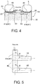
- Figure 4 is a cross sectional view of the seat bottom as viewed along the section line B-B of Figure 2 ;
- Figure 5 is an enlarged schematic view of a region C of the seat bottom shown in Figure 2 ;
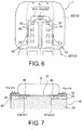
- Figure 6 is an elevational view of the seat back of the vehicle seat shown in Figure 1 ;
- Figure 7 is a cross sectional view of the seat back as viewed along the section line 7-7 of Figure 6 ;
- Figure 8 is a cross sectional view, similar to Figure 3 , of a seat bottom showing a variation in which the air passage is different.
- a vehicle seat 1 is illustrated in accordance with a first embodiment.
- the vehicle seat 1 has a seat bottom 1A and a seat back 1B serving as seat bodies.
- the seat bottom 1 A and the seat back 1B are attached to a seat frame I C.
- the seat bottom 1A includes a seat cushion pad 20, a breathable seat outer cover 21 and an air permeable material layer 22.
- the seat outer cover 21 covers at least a portion of an outer surface of the seat cushion pad 20.
- the air permeable material layer 22 is disposed between the seat outer cover 21 and the seat cushion pad 20 at least along portions of the upper sitting surface of the seat cushion pad 20.
- the seat cushion pad 20 is made of an elastic material, e.g., urethane foam, that has a standard spring constant that is typically required for a vehicle seat cushion.
- an elastic material e.g., urethane foam
- the seat outer cover 21 is a breathable outer cover that is made of a breathable material such as a breathable fabric, a natural leather, a synthetic leather, or an artificial leather
- the air permeable material layer 22 is made of an elastic sheet material, e.g., a mesh-like urethane foam, through which air can pass in multiple directions within the layer. It is acceptable for the air permeable material layer 22 to be a single large member that covers a wide area corresponding to an entire sitting surface of the seat bottom 1A, i.e., an entire seated passenger support surface. However, in this embodiment the air permeable material layer 22 is formed as a pair of left and right strips corresponding to portions that support the thighs of both legs a seated passenger as shown in Figure 2.
- Figure 2 depicts the seat with the seat outer cover 21 removed for purposes of illustration.
- the seat back 1B includes a cushion pad 30, a breathable seat outer cover 31 and an air permeable material layer 32.
- the seat outer cover 31 covers at least a portion of an outer surface of the seat cushion pad 30.
- the air permeable material layer 32 is disposed between the seat outer cover 31 and the seat cushion pad 30 at least along portions of the upper sitting surface of the seat cushion pad 30.
- the cushion pad 30 has a prescribed spring constant, similar to the cushion pad 20.
- the air permeable material layer 32 is made such that air can pass through in multiple directions within the layer in the same manner as the air permeable material layer 22.
- Figure 6 depicts the seat with the seat outer cover 21 removed for purposes of illustration, similar to Figure 2 .
- the air permeable material layer 32 is formed as a pair of left and right strips.
- the left and right strips of the air permeable material layer 32 are arranged on left and right sides of a back support surface that serves as a seated passenger support surface.
- the left and right strips are arranged corresponding to portions that support portions of a seated passenger's back located on both sides of the seated passenger's spine.
- Both of the air permeable material layers 22 and 32 of the seat bottom 1A and the seat back 1B have a plurality of the vent outlets 40.
- the vent outlets 40 are arranged on both vehicle-widthwise sides.
- Each of the cushion pads 20 and 30 has at least one air passage 41.
- the air passage 41 of the cushion pad 20 is in communication with the vent outlets 40 that are provided in the cushion pad 20.
- the air passage 41 of the cushion pad 30 is in communication with the vent outlets 40 that are provided in the cushion pad 30.
- the vent outlets 40 extend through the air permeable material layers 22 and 32 in a thickness direction of the air permeable material layers 22 and 32.
- the air passages 41 are arranged to deliver blown air to the vent outlets 40.
- the vent outlets 40 of the air permeable material layer 22 of the seat bottom 1A are arranged in columns that are oriented along a vehicle-longitudinal direction of the sitting surface of the seat bottom 1A.
- the vent outlets 40 of the air permeable material layer 32 of the seat back 1B are arranged in columns that are oriented along a vertical direction of the back supporting surface of the seat back 1B.
- Each of the air passages 41 is connected to an air introducing port 42 that is provided on a back surface of the seat cushion pad 20 or 30.
- Each of the air passages 41 branches into a plurality of air passages.
- Each of the air passages 41 opens at a border surface where the seat cushion pad 20 or 30 borders with the air permeable material layer 22 or 32. In this way, each of the air passages 41 distributes air from an air blower 50 to the vent outlets 40.
- the air introducing port 42 of the seat bottom 1A is provided in a substantially middle portion positioned toward a rearward end of the seat cushion pad 20.
- the air passage 41 includes a main passage 41a and a branch passage 41b
- the main passage 41a passes through the seat cushion pad 20 in a vertical direction and connects to the air introduction port 42 at a bottom end.
- the branch passage 41b branches into a plurality of branches at an upper surface of the seat cushion pad 20.
- the branch passage 41 b connects the main passage 41a to the vent outlets 40 of the air permeable material layer 22.
- the branch passage 41b is configured as a trough-like section that is open on a side corresponding to the border surface with respect to the air permeable material layer 22.
- the branch passage 41b has an H-like shape with portions that extend in a longitudinal direction on the left and right sides so as to span across vent outlets 40 and a middle portion that passes over the main passage 41a (see Figures 2 and 3 ).
- the air introducing port 42 of the seat back 1 B is provided in a substantially middle portion positioned toward an upper end of the cushion pad 30.
- the air passage 41 includes a main passage 41a and a branch passage 41b.
- the main passage 41a that passes through the cushion pad 30 in a rear-to-front direction and connects to the air introduction port 42 at a rearward end.
- the branch passage 41 b branches into a plurality of branches at a frontward surface of the cushion pad 30.
- the branch passage 41b connects the main passage 41a to the vent outlets 40 of the air permeable material layer 32.
- the branch passage 41b is configured as a trough-like section that is open on a side corresponding to the border surface with respect to the air permeable material layer 32.
- the branch passage 41 b has a U-like shape with portions that extend in a vertical direction on the left and right sides so as to span across the vent outlets 40 and an upper portion that passes over the main passage 41a (see Figure 6 ).
- the air blower 50 is installed, for example, on a vehicle body floor below the seat bottom 1A.
- the air blower 50 has two air discharge ports 51A and 5 1 B.
- the air discharge port 51 A is connected to the air introducing port 42 of the seat bottom 1 A through a plurality of connecting ducts 52A.
- the air discharge port 51 B is connected to the air introducing port 42 of the seat back 1 B through a plurality of connecting ducts 52B.
- bypass air passages 43 oriented in a widthwise direction of the vehicle are provided in the branch passages 41 b of the air passages 41 at portions where the branch passages 41 b communicate with the vent outlet 40.
- Each of the bypass air passages 43 is configured as a trough-like section that is open on a side corresponding to the border surface with respect to the air permeable material layer 22 or 32 and closed at a terminal end. Air blown into the air passages 41 can be blown in a planar direction to the air permeable material layers 22 and 32.
- the blown air can be blown in a planar direction to the air permeable material layer 22 due to the bypass air passage 43 of the cushion pad 20 or 30 even when small openings of the breathable seat outer cover 21 or 31 of the seat bottom 1 A or the seat back 1B and the vent outlets 40 of the air permeable material layer 22 or 32 are crushed or blocked by the weight of a seated passenger.
- blown air can pass through portions where the small openings of the air permeable material layer 22 or 32 and the seat outer cover 21 or 31 are not crushed and blow onto the seated passenger.
- the bypass air passages 43 are provided in a downstream region of branch passage 41 b toward a frontward end of the seat bottom 1A such that the bypass air passages 43 are oriented inwardly in a widthwise direction of the vehicle.
- the bypass air passages 43 are provided in a downstream region of branch passage 41b toward a lower end of the seat back 1B such that the bypass air passages 43 are oriented outwardly in a widthwise direction of the vehicle.
- Figure 5 shows a portion where an air passage 41 communicates with bypass air passages 43; each of the bypass air passages 43 is configured such that a passage size thereof narrows as one moves toward a terminal end.
- the bypass air passages 43 are configured to form an obtuse angle ⁇ of 90 degrees or larger with respect to a flow direction of blown air in the branch passage 41 b of the air passage 41.
- conditioned air from inside a vehicle cabin that is blown from the air discharge ports 51A and 51 B of the air blower 50 passes through the connecting ducts 52A and 52B and into the air introducing ports 42 of the seat bottom 1A and the seat back 1B.
- the blown air introduced to the air introducing port 42 is distributed from the main passage 41a of the air passage 41 inside the seat cushion pad 20 to the branch passage 41b.
- the blown air distributed to the branch passage 41 b is introduced substantially uniformly to the vent outlets 40 provided in the air permeable material layers 22 provided on both vehicle-widthwise sides.
- Air blown from the vent ports 40 passes through fine ventilation holes (small openings) in the seat outer cover 21 and is discharged at the sitting surface.
- conditioned air can be ventilated (blown) to a lower body (spanning from a buttock portion across a length of the thighs of both legs) of a passenger seated on the seat bottom 1A such that a comfortable sitting environment can be created in which heat and humidity are not trapped at the sitting surface.
- the blown air introduced to the air introducing port 42 is distributed from the main passage 41a of the air passage 41 inside the cushion pad 30 to the branch passage 41b.
- the blown air distributed to the branch passage 41b is introduced substantially uniformly to the vent outlets 40 provided in the air permeable material layers 32 provided on both vehicle-widthwise sides.
- Air blown from the vent ports 40 passes through fine ventilation holes (small openings) in the seat outer cover 31 and is discharged at the back support surface As a result, conditioned air can be ventilated (blown) to an upper body (spanning from a lower back area to a portion near a shoulder area) of a passenger whose back rests on the seat back 1B such that a comfortable sitting environment can be created in which heat and humidity are not trapped at the back support surface.
- the air permeable material layers 22 and 32 are made so that air can pass through the insides of the layers in multiple directions, providing vent outlets 40 and configuring the air passages 41 to guide the blown air to the vent outlets 40 enables the blown air to be concentrated at the vent ports 40 and to be discharged from the seat outer covers 21 and 31 with a prescribed range of spread centered at portions corresponding to the vent outlets 40.
- vent outlets 40 are arranged in columns oriented in a direction perpendicular to a vehicle-widthwise direction of the seated passenger support surfaces, conditioned air can be discharged along portions of the seat bottom I A corresponding to the buttocks and thighs of a seated passenger and along portions of the seat back 1B corresponding to both sides of a seated passenger's spine. That is, ventilation can be concentrated at portions where a seated passenger makes close contact and heat and humidity are easily trapped, and a refreshing feeling can be increased.
- the ventilation holes (small openings) of the seat outer covers 21 and 31 and the vent outlets 40 of the air permeable material layers 22 and 33 could feasibly become blocked or crushed by pressure caused by the weight of the seated passenger.
- bypass air passages 43 oriented in a widthwise direction of the vehicle are provided in portions where the air passages 41 communicate with the vent outlets 40.
- Each of the bypass air passages 43 is open on a side corresponding to a border surface with respect to the air permeable material layer 22 or 32, arranged to extend in a widthwise direction of the vehicle, and closed at a terminal end.
- the blown air is allowed to flow in multiple directions through the insides of the air permeable material layers 22 and 32 near the blocked vent outlets 40 and the seat outer covers 21 and 31 can be ventilated such that a decline in ventilation performance can be avoided.
- the bypass air passages 43 are configured to be oriented toward a middle of the seat bottom 1A in a widthwise direction of the vehicle, as shown in Figure 4 . Consequently, the blown air can be ventilated to an area between the thighs L of both legs and a refreshing feeling can be well maintained.
- the air passage 41 is configured such that downstream portions thereof are located toward a frontward end of the seat bottom 1A. Since the bypass passages 43 are provided in this downstream region of the air passage 41, the blown air can be ventilated to an area between frontward end portions of the thighs L where the space between the thighs L widens and the ventilation performance can be improved. Providing the bypass air passages 43 in a downstream region of the air passage 41 enables blown air to flow more readily to the bypass air passages 43 and helps further improve the aforementioned ventilation performance.
- the bypass air passages 43 are configured to be oriented toward the outsides of the seat back 1B in a widthwise direction of the vehicle, as shown in Figure 7 . Consequently, the bypass air passages 43 can be disposed in portions separated from a region where a seated passenger makes close contact, a decline of the ventilation performance can be avoided, and heat and humidity can be prevented from being trapped in the region where the seated passenger makes close contact.
- the air passage 41 is configured such that downstream portions thereof are located toward a lower end of the seat back 1B. Since the bypass passages 43 are provided in this downstream region of the air passage 41, the ventilation performance can be improved at a portion corresponding to a lower back area B of a seated passenger, where heat accumulation and humidity occur more severely, and an excellent refreshing feeling can be obtained. Moreover, in the seat back 1B, too, providing the bypass air passages 43 in a downstream region of the air passage 41 enables blown air to flow more readily to the bypass air passages 43 and helps further improve the aforementioned ventilation performance.
- the portion of the air passage that communicates with the vent outlets 40 i.e., the branch passage 41b, is configured as a trough-like section that is open on a side corresponding to a border surface with respect to the air permeable material layer 22 or 32 and extends so as to span across the vent outlets 40 arranged in a column along one direction.
- a consistency of communication between the vent outlets 40 and the air passage 41 can be increased because the communication between the air passage 41 and the vent outlets arranged in a column along one direction can be concentrated at a single trough-like section. Additionally, since the branch passage 41 b is configured to be open at a surface of the seat cushion pad 20 or 30, the forming of the cushion pads 20 and 30 can be accomplished more easily.
- each of the bypass air passages 43 is formed such that a passage size thereof narrows as one moves toward a terminal end, the flow speed of the blown air can be made to increase as the blown air approaches the terminal end, thus contributing to improving the ventilation performance.
- the bypass air passages 43 are configured to form an obtuse angle ⁇ of 90 degrees or larger with respect to a flow direction of blown air flowing toward a downstream portion of the branch passage 41b. Consequently, the bypass air passages 43 take in blown air readily and can contribute to improving the ventilation performance.
- Figure 8 shows a variation in which the air passages 41 are configured differently and uses the seat bottom 1 A as a representative example of a seat body.
- both the main passage 41a and the branch passages 41 b of the air passage 41 are formed within the thickness of the seat cushion pad 20.
- the main passage 41a is formed along a single direction aligned with a direction in which the vent outlets 40 are arranged.
- the branch passages 41 b are provided such that they communicate with each of the vent outlets 40 arranged along a signal direction and communicate with the main passage 41a in a thickness direction of the seat cushion pad 20.
- bypass air passages 43 are provided in a downstream region of the air passage 41, it is clearly acceptable to provide bypass air passages oriented in a widthwise direction of the vehicle at portions where the air passage 41 communicates with each of the vent outlets 40.
Applications Claiming Priority (1)
| Application Number | Priority Date | Filing Date | Title |
|---|---|---|---|
| JP2011088719A JP2012218655A (ja) | 2011-04-13 | 2011-04-13 | 車両用シート |
Publications (1)
| Publication Number | Publication Date |
|---|---|
| EP2511128A2 true EP2511128A2 (en) | 2012-10-17 |
Family
ID=45808156
Family Applications (1)
| Application Number | Title | Priority Date | Filing Date |
|---|---|---|---|
| EP12001353A Withdrawn EP2511128A2 (en) | 2011-04-13 | 2012-02-29 | Vehicle seat |
Country Status (4)
| Country | Link |
|---|---|
| US (1) | US8662579B2 (ja) |
| EP (1) | EP2511128A2 (ja) |
| JP (1) | JP2012218655A (ja) |
| CN (1) | CN102729863A (ja) |
Cited By (2)
| Publication number | Priority date | Publication date | Assignee | Title |
|---|---|---|---|---|
| US20130300179A1 (en) * | 2012-05-09 | 2013-11-14 | Toyota Boshoku Kabushiki Kaisha | Vehicle seat |
| EP3330125A1 (fr) * | 2016-11-30 | 2018-06-06 | FAURECIA Sièges d'Automobile | Siège de véhicule et élément de siège comprenant un système de ventilation ergonomique |
Families Citing this family (104)
| Publication number | Priority date | Publication date | Assignee | Title |
|---|---|---|---|---|
| DE202009017050U1 (de) * | 2008-12-21 | 2010-05-12 | W.E.T. Automotive Systems Ag | Belüftungseinrichtung |
| DE112012007008T5 (de) * | 2012-10-11 | 2015-07-02 | Kongsberg Automotive Inc. | Ventilierter und beheizter Fahrzeugsitzaufbau |
| US9126508B2 (en) | 2013-01-24 | 2015-09-08 | Ford Global Technologies, Llc | Upper seatback pivot system |
| US9096157B2 (en) | 2013-01-24 | 2015-08-04 | Ford Global Technologies, Llc | Seating assembly with air distribution system |
| US9902293B2 (en) | 2013-01-24 | 2018-02-27 | Ford Global Technologies, Llc | Independent cushion extension with optimized leg-splay angle |
| US9016783B2 (en) | 2013-01-24 | 2015-04-28 | Ford Global Technologies, Llc | Thin seat flex rest composite cushion extension |
| US9061616B2 (en) | 2013-01-24 | 2015-06-23 | Ford Global Technologies, Llc | Articulating headrest assembly |
| US9409504B2 (en) | 2013-01-24 | 2016-08-09 | Ford Global Technologies, Llc | Flexible seatback system |
| US9126504B2 (en) | 2013-01-24 | 2015-09-08 | Ford Global Technologies, Llc | Integrated thin flex composite headrest assembly |
| US9415713B2 (en) | 2013-01-24 | 2016-08-16 | Ford Global Technologies, Llc | Flexible seatback system |
| US9399418B2 (en) | 2013-01-24 | 2016-07-26 | Ford Global Technologies, Llc | Independent cushion extension and thigh support |
| US8727374B1 (en) | 2013-01-24 | 2014-05-20 | Ford Global Technologies, Llc | Vehicle seatback with side airbag deployment |
| US9216677B2 (en) | 2013-01-24 | 2015-12-22 | Ford Global Technologies, Llc | Quick-connect trim carrier attachment |
| US9016784B2 (en) | 2013-01-24 | 2015-04-28 | Ford Global Technologies, Llc | Thin seat leg support system and suspension |
| US9056570B2 (en) | 2013-02-27 | 2015-06-16 | The Boeing Company | Variable thermal resistance device for vehicular seats |
| US9440572B2 (en) | 2013-05-20 | 2016-09-13 | David R. Hall | Heating, ventilation, and air conditioning seat assembly |
| US9193284B2 (en) | 2013-06-11 | 2015-11-24 | Ford Global Technologies, Llc | Articulating cushion bolster for ingress/egress |
| CN105491915B (zh) | 2013-08-30 | 2019-08-30 | 提爱思科技股份有限公司 | 座椅 |
| US9527418B2 (en) | 2013-09-12 | 2016-12-27 | Ford Global Technologies, Llc | Semi rigid push/pull vented envelope system |
| US8905431B1 (en) | 2013-09-24 | 2014-12-09 | Ford Global Technologies, Llc | Side airbag assembly for a vehicle seat |
| US9187019B2 (en) | 2013-10-17 | 2015-11-17 | Ford Global Technologies, Llc | Thigh support for customer accommodation seat |
| US9505322B2 (en) | 2013-10-25 | 2016-11-29 | Ford Global Technologies, Llc | Manual lumbar pump assembly |
| US9566884B2 (en) | 2013-11-11 | 2017-02-14 | Ford Global Technologies, Llc | Powered head restraint electrical connector |
| US9315130B2 (en) | 2013-11-11 | 2016-04-19 | Ford Global Technologies, Llc | Articulating head restraint |
| US9365143B2 (en) | 2013-12-12 | 2016-06-14 | Ford Global Technologies, Llc | Rear seat modular cushion |
| US9315131B2 (en) | 2014-01-23 | 2016-04-19 | Ford Global Technologies, Llc | Suspension seat back and cushion system having an inner suspension panel |
| US9649963B2 (en) | 2014-03-04 | 2017-05-16 | Ford Global Technologies, Pllc | Trim and foam assembly for a vehicle seat |
| US9527419B2 (en) | 2014-03-31 | 2016-12-27 | Ford Global Technologies, Llc | Vehicle seating assembly with manual cushion tilt |
| US9302643B2 (en) | 2014-04-02 | 2016-04-05 | Ford Global Technologies, Llc | Vehicle seating assembly with side airbag deployment |
| US9421894B2 (en) | 2014-04-02 | 2016-08-23 | Ford Global Technologies, Llc | Vehicle seating assembly with manual independent thigh supports |
| US9694741B2 (en) | 2014-08-25 | 2017-07-04 | Ford Global Technologies, Llc | Ambient functional lighting of a seat |
| US10471874B2 (en) | 2014-09-02 | 2019-11-12 | Ford Global Technologies, Llc | Massage bladder matrix |
| US9333882B2 (en) | 2014-10-03 | 2016-05-10 | Ford Global Technologies, Llc | Manual upper seatback support |
| US9776533B2 (en) | 2014-10-03 | 2017-10-03 | Ford Global Technologies, Llc | Torsion bar upper seatback support assembly |
| US9789790B2 (en) | 2014-10-03 | 2017-10-17 | Ford Global Technologies, Llc | Tuned flexible support member and flexible suspension features for comfort carriers |
| US9771003B2 (en) | 2014-10-29 | 2017-09-26 | Ford Global Technologies, Llc | Apparatus for customizing a vehicle seat for an occupant |
| US9340131B1 (en) | 2014-11-06 | 2016-05-17 | Ford Global Technologies, Llc | Head restraint with a multi-cell bladder assembly |
| US9517777B2 (en) | 2014-11-06 | 2016-12-13 | Ford Global Technologies, Llc | Lane departure feedback system |
| US10065570B2 (en) | 2014-12-10 | 2018-09-04 | Ford Global Technologies, Llc | Electronic device holder for a vehicle seat |
| US9593642B2 (en) | 2014-12-19 | 2017-03-14 | Ford Global Technologies, Llc | Composite cam carrier |
| US9663000B2 (en) | 2015-01-16 | 2017-05-30 | Ford Global Technologies, Llc | Vehicle seat configured to improve access |
| US9365142B1 (en) | 2015-01-20 | 2016-06-14 | Ford Global Technologies, Llc | Manual independent thigh extensions |
| US9707877B2 (en) | 2015-01-20 | 2017-07-18 | Ford Global Technologies, Llc | Independent thigh extension and support trim carrier |
| JP6480208B2 (ja) * | 2015-02-13 | 2019-03-06 | テイ・エス テック株式会社 | シート |
| JP6427025B2 (ja) * | 2015-02-13 | 2018-11-21 | テイ・エス テック株式会社 | シート |
| US9566930B2 (en) | 2015-03-02 | 2017-02-14 | Ford Global Technologies, Llc | Vehicle seat assembly with side-impact airbag deployment mechanism |
| US9802535B2 (en) | 2015-04-27 | 2017-10-31 | Ford Global Technologies, Llc | Seat having ambient lighting |
| JP6458644B2 (ja) * | 2015-05-26 | 2019-01-30 | トヨタ紡織株式会社 | 乗物用空調シート |
| US10046682B2 (en) | 2015-08-03 | 2018-08-14 | Ford Global Technologies, Llc | Back cushion module for a vehicle seating assembly |
| US9718387B2 (en) | 2015-08-03 | 2017-08-01 | Ford Global Technologies, Llc | Seat cushion module for a vehicle seating assembly |
| US9688174B2 (en) | 2015-08-07 | 2017-06-27 | Ford Global Technologies, Llc | Multi-cell seat cushion assembly |
| US9573528B1 (en) | 2015-08-25 | 2017-02-21 | Ford Global Technologies, Llc | Integrated seatback storage |
| US9616776B1 (en) | 2015-11-16 | 2017-04-11 | Ford Global Technologies, Llc | Integrated power thigh extender |
| US9809131B2 (en) | 2015-12-04 | 2017-11-07 | Ford Global Technologies, Llc | Anthropomorphic pivotable upper seatback support |
| US9931999B2 (en) | 2015-12-17 | 2018-04-03 | Ford Global Technologies, Llc | Back panel lower clip anchorage features for dynamic events |
| US10093214B2 (en) | 2016-01-14 | 2018-10-09 | Ford Global Technologies, Llc | Mechanical manual leg tilt |
| US9914421B2 (en) | 2016-01-15 | 2018-03-13 | Ford Global Technologies, Llc | Seatback flexible slip plane joint for side air bag deployment |
| US10052990B2 (en) | 2016-01-25 | 2018-08-21 | Ford Global Technologies, Llc | Extended seatback module head restraint attachment |
| US20170210263A1 (en) * | 2016-01-25 | 2017-07-27 | Ford Global Technologies, Llc | Integrated independent thigh supports |
| US9756408B2 (en) | 2016-01-25 | 2017-09-05 | Ford Global Technologies, Llc | Integrated sound system |
| US9776543B2 (en) | 2016-01-25 | 2017-10-03 | Ford Global Technologies, Llc | Integrated independent thigh supports |
| US10035442B2 (en) | 2016-01-25 | 2018-07-31 | Ford Global Technologies, Llc | Adjustable upper seatback module |
| US10240607B2 (en) * | 2016-02-26 | 2019-03-26 | Kongsberg Automotive, Inc. | Blower assembly for a vehicle seat |
| US9849817B2 (en) | 2016-03-16 | 2017-12-26 | Ford Global Technologies, Llc | Composite seat structure |
| US10046681B2 (en) | 2016-04-12 | 2018-08-14 | Ford Global Technologies, Llc | Articulating mechanical thigh extension composite trim payout linkage system |
| US10286818B2 (en) | 2016-03-16 | 2019-05-14 | Ford Global Technologies, Llc | Dual suspension seating assembly |
| US9994135B2 (en) | 2016-03-30 | 2018-06-12 | Ford Global Technologies, Llc | Independent cushion thigh support |
| US10220737B2 (en) | 2016-04-01 | 2019-03-05 | Ford Global Technologies, Llc | Kinematic back panel |
| US9889773B2 (en) | 2016-04-04 | 2018-02-13 | Ford Global Technologies, Llc | Anthropomorphic upper seatback |
| US10625646B2 (en) | 2016-04-12 | 2020-04-21 | Ford Global Technologies, Llc | Articulating mechanical thigh extension composite trim payout linkage system |
| US9802512B1 (en) | 2016-04-12 | 2017-10-31 | Ford Global Technologies, Llc | Torsion spring bushing |
| US10081279B2 (en) | 2016-04-12 | 2018-09-25 | Ford Global Technologies, Llc | Articulating thigh extension trim tensioning slider mechanism |
| CN105877264A (zh) * | 2016-05-27 | 2016-08-24 | 南京嘉涛科技有限公司 | 一种双管个体送风座椅 |
| US9845029B1 (en) | 2016-06-06 | 2017-12-19 | Ford Global Technologies, Llc | Passive conformal seat with hybrid air/liquid cells |
| US9849856B1 (en) | 2016-06-07 | 2017-12-26 | Ford Global Technologies, Llc | Side airbag energy management system |
| US9834166B1 (en) | 2016-06-07 | 2017-12-05 | Ford Global Technologies, Llc | Side airbag energy management system |
| US10377279B2 (en) | 2016-06-09 | 2019-08-13 | Ford Global Technologies, Llc | Integrated decking arm support feature |
| US10166895B2 (en) | 2016-06-09 | 2019-01-01 | Ford Global Technologies, Llc | Seatback comfort carrier |
| US10286824B2 (en) | 2016-08-24 | 2019-05-14 | Ford Global Technologies, Llc | Spreader plate load distribution |
| US10279714B2 (en) | 2016-08-26 | 2019-05-07 | Ford Global Technologies, Llc | Seating assembly with climate control features |
| US10239431B2 (en) | 2016-09-02 | 2019-03-26 | Ford Global Technologies, Llc | Cross-tube attachment hook features for modular assembly and support |
| US10391910B2 (en) | 2016-09-02 | 2019-08-27 | Ford Global Technologies, Llc | Modular assembly cross-tube attachment tab designs and functions |
| JP6783597B2 (ja) * | 2016-09-15 | 2020-11-11 | 株式会社タチエス | 車両用シート |
| WO2018079041A1 (ja) * | 2016-10-24 | 2018-05-03 | 株式会社デンソー | 通風シートおよび座席空調装置 |
| US9914378B1 (en) | 2016-12-16 | 2018-03-13 | Ford Global Technologies, Llc | Decorative and functional upper seatback closeout assembly |
| JP6763294B2 (ja) * | 2016-12-21 | 2020-09-30 | トヨタ紡織株式会社 | 乗物用シート |
| JP6693492B2 (ja) * | 2017-01-24 | 2020-05-13 | 株式会社デンソー | シート空調装置 |
| US10596936B2 (en) | 2017-05-04 | 2020-03-24 | Ford Global Technologies, Llc | Self-retaining elastic strap for vent blower attachment to a back carrier |
| WO2018216610A1 (ja) | 2017-05-23 | 2018-11-29 | テイ・エス テック株式会社 | 乗物用シート |
| US10532674B2 (en) | 2017-08-01 | 2020-01-14 | Faurecia Automotive Seating, Llc | Vehicle seat |
| CN107348730A (zh) * | 2017-08-17 | 2017-11-17 | 浙江安吉忠鑫家具有限公司 | 一种舒适排椅 |
| WO2019080957A1 (de) * | 2017-10-27 | 2019-05-02 | Gentherm Gmbh | Oberflächen-temperiereinrichtung |
| FR3072912B1 (fr) * | 2017-10-27 | 2019-11-01 | Faurecia Sieges D'automobile | Element de siege avec un systeme de ventilation |
| US10479243B2 (en) | 2017-12-05 | 2019-11-19 | Ford Global Technologies, Llc | Air channel thermocomfort foam pad |
| JP7114941B2 (ja) * | 2018-03-05 | 2022-08-09 | 株式会社デンソー | 車両用シート装置 |
| US10556526B2 (en) * | 2018-04-30 | 2020-02-11 | Faurecia Automotive Seating, Llc | Ventilated vehicle seat with passive vent panel |
| JP7262935B2 (ja) * | 2018-06-11 | 2023-04-24 | 株式会社タチエス | 車両用シート |
| DE102018218494A1 (de) * | 2018-10-29 | 2020-04-30 | Volkswagen Aktiengesellschaft | Fahrzeugsitz für ein Kraftfahrzeug |
| CN111845497A (zh) * | 2018-12-11 | 2020-10-30 | 黄河科技学院 | 具有调节透气的汽车座椅 |
| KR20210111960A (ko) * | 2020-03-04 | 2021-09-14 | 현대자동차주식회사 | 자동차의 슬림 시트용 통풍 장치 |
| KR20220123995A (ko) * | 2021-03-02 | 2022-09-13 | 현대두산인프라코어(주) | 건설 기계 |
| CN114435208A (zh) * | 2021-12-09 | 2022-05-06 | 深圳斯诺凡科技有限公司 | 一种座椅通风系统及其总成安装方法 |
| US11858387B2 (en) * | 2022-04-01 | 2024-01-02 | GM Global Technology Operations LLC | Seat assembly |
| CN115352335B (zh) * | 2022-09-14 | 2023-07-18 | 广州吉中汽车内饰系统有限公司 | 一种汽车座椅坐垫总成 |
Citations (1)
| Publication number | Priority date | Publication date | Assignee | Title |
|---|---|---|---|---|
| JPH09505499A (ja) | 1993-11-22 | 1997-06-03 | アメリゴン,インコーポレイティド | 温度変更可能な座席 |
Family Cites Families (22)
| Publication number | Priority date | Publication date | Assignee | Title |
|---|---|---|---|---|
| US6179706B1 (en) * | 1998-06-19 | 2001-01-30 | Denso Corporation | Seat air conditioner for vehicle |
| EP1086852B1 (de) * | 1999-09-21 | 2004-01-28 | Johnson Controls GmbH | Sitzpolster für Fahrzeugsitze |
| JP2002127795A (ja) * | 2000-10-25 | 2002-05-08 | Nippon Mitsubishi Oil Corp | 空調機能付チャイルドシート |
| DE20112473U1 (de) * | 2001-07-28 | 2002-12-19 | Johnson Controls Gmbh | Klimatisiertes Polsterteil für einen Fahrzeugsitz |
| JP3835329B2 (ja) * | 2002-03-28 | 2006-10-18 | 株式会社デンソー | 車両用シート空調装置 |
| JP3804566B2 (ja) * | 2002-03-28 | 2006-08-02 | 株式会社デンソー | 車両用シート空調装置 |
| DE10243315B4 (de) * | 2002-09-18 | 2005-11-17 | Daimlerchrysler Ag | Polster für einen Fahrzeugsitz |
| US7168758B2 (en) * | 2003-06-05 | 2007-01-30 | Igb Automotive Ltd. | Modular comfort assembly for occupant support |
| JP4513555B2 (ja) * | 2004-12-24 | 2010-07-28 | 株式会社デンソー | 車両用シート空調装置 |
| US20060214480A1 (en) * | 2005-03-23 | 2006-09-28 | John Terech | Vehicle seat with thermal elements |
| KR20060106507A (ko) * | 2005-04-09 | 2006-10-12 | 한라공조주식회사 | 차량용 시트 공조장치 |
| JP5103114B2 (ja) * | 2007-09-25 | 2012-12-19 | トヨタ紡織株式会社 | 空調シート |
| JP2009090016A (ja) * | 2007-10-11 | 2009-04-30 | T S Tec Kk | シート並びにその座部及びバックレスト |
| US20090218855A1 (en) * | 2008-02-26 | 2009-09-03 | Amerigon Incorporated | Climate control systems and devices for a seating assembly |
| JP2009286216A (ja) * | 2008-05-28 | 2009-12-10 | Denso Corp | 風圧発生装置 |
| US7802843B2 (en) * | 2008-08-13 | 2010-09-28 | Lear Corporation | Flexible noise cover for a ventilated seat |
| DE102008038380B4 (de) * | 2008-08-19 | 2010-11-11 | Lear Corp., Southfield | Ausrichtungssystem für eine Abstandsschicht in einem belüfteten Sitz |
| JP5349906B2 (ja) * | 2008-10-29 | 2013-11-20 | トヨタ紡織株式会社 | 車両用シートのクッション構造体 |
| US20100295339A1 (en) * | 2009-05-22 | 2010-11-25 | David S.K. Siu | Air-conditioned seat cushion |
| US20110260509A1 (en) * | 2009-05-22 | 2011-10-27 | Siu David S K | Structurally improved seat cushion |
| JP5528745B2 (ja) * | 2009-09-10 | 2014-06-25 | 東洋ゴム工業株式会社 | 車両用シートパッド |
| JP5556156B2 (ja) * | 2009-12-08 | 2014-07-23 | トヨタ紡織株式会社 | 車両用シート |
-
2011
- 2011-04-13 JP JP2011088719A patent/JP2012218655A/ja active Pending
-
2012
- 2012-02-22 CN CN2012100419868A patent/CN102729863A/zh active Pending
- 2012-02-29 EP EP12001353A patent/EP2511128A2/en not_active Withdrawn
- 2012-03-01 US US13/410,116 patent/US8662579B2/en not_active Expired - Fee Related
Patent Citations (1)
| Publication number | Priority date | Publication date | Assignee | Title |
|---|---|---|---|---|
| JPH09505499A (ja) | 1993-11-22 | 1997-06-03 | アメリゴン,インコーポレイティド | 温度変更可能な座席 |
Cited By (3)
| Publication number | Priority date | Publication date | Assignee | Title |
|---|---|---|---|---|
| US20130300179A1 (en) * | 2012-05-09 | 2013-11-14 | Toyota Boshoku Kabushiki Kaisha | Vehicle seat |
| US9073466B2 (en) * | 2012-05-09 | 2015-07-07 | Toyota Boshoku Kabushiki Kaisha | Vehicle seat |
| EP3330125A1 (fr) * | 2016-11-30 | 2018-06-06 | FAURECIA Sièges d'Automobile | Siège de véhicule et élément de siège comprenant un système de ventilation ergonomique |
Also Published As
| Publication number | Publication date |
|---|---|
| CN102729863A (zh) | 2012-10-17 |
| US20120261974A1 (en) | 2012-10-18 |
| US8662579B2 (en) | 2014-03-04 |
| JP2012218655A (ja) | 2012-11-12 |
Similar Documents
| Publication | Publication Date | Title |
|---|---|---|
| US8662579B2 (en) | Vehicle seat | |
| CN102059968B (zh) | 适用于制冷和加热的车辆座椅 | |
| US20070200398A1 (en) | Climate controlled seat | |
| JP5419218B2 (ja) | ダクト入りシートクッション | |
| US20150329029A1 (en) | Vehicle seat | |
| US7052090B2 (en) | Adaptive pneumatic seat and backrest cushions for vehicles and airplanes | |
| WO2008043416A3 (de) | Aktiv belüfteter fahrzeugsitz | |
| JP2015107744A (ja) | 通気性シート | |
| US20090302646A1 (en) | Cushion for a Vehicle Seat | |
| JP6423732B2 (ja) | 車両用シート | |
| WO2016158042A1 (ja) | 車両用シート | |
| US11072266B2 (en) | Vehicle seat | |
| JP2018039298A (ja) | 車両用シート | |
| JP4347646B2 (ja) | クッションパッド | |
| DE102014004415A1 (de) | Sitzelement für eine Sitzanlage eines Kraftwagens | |
| US7328944B2 (en) | Contour motorcycle seat | |
| JP7280043B2 (ja) | シートパッド | |
| US10351034B2 (en) | Pressure medium distributor, pnuematic adjustment arrangement for a vehicle seat, vehicle seat, and method for producing a pressure medium distributor for a pneumatic adjustment arrangement | |
| KR101683484B1 (ko) | 차량용 통풍패드 | |
| JP2018118719A (ja) | シート空調装置 | |
| US9469228B2 (en) | Seat climate control assembly and seat employing the same | |
| US10144470B2 (en) | Vehicle seat | |
| KR101210223B1 (ko) | 시트쿠션 | |
| KR200476295Y1 (ko) | 통풍 시트 | |
| JP2017114214A (ja) | 車両用シート |
Legal Events
| Date | Code | Title | Description |
|---|---|---|---|
| PUAI | Public reference made under article 153(3) epc to a published international application that has entered the european phase |
Free format text: ORIGINAL CODE: 0009012 |
|
| 17P | Request for examination filed |
Effective date: 20120229 |
|
| AK | Designated contracting states |
Kind code of ref document: A2 Designated state(s): AL AT BE BG CH CY CZ DE DK EE ES FI FR GB GR HR HU IE IS IT LI LT LU LV MC MK MT NL NO PL PT RO RS SE SI SK SM TR |
|
| AX | Request for extension of the european patent |
Extension state: BA ME |
|
| STAA | Information on the status of an ep patent application or granted ep patent |
Free format text: STATUS: THE APPLICATION IS DEEMED TO BE WITHDRAWN |
|
| 18D | Application deemed to be withdrawn |
Effective date: 20150901 |