EP2509169A1 - Connecteur latéral de véhicule - Google Patents
Connecteur latéral de véhicule Download PDFInfo
- Publication number
- EP2509169A1 EP2509169A1 EP20120001650 EP12001650A EP2509169A1 EP 2509169 A1 EP2509169 A1 EP 2509169A1 EP 20120001650 EP20120001650 EP 20120001650 EP 12001650 A EP12001650 A EP 12001650A EP 2509169 A1 EP2509169 A1 EP 2509169A1
- Authority
- EP
- European Patent Office
- Prior art keywords
- vehicle
- recess
- side connector
- connecting portion
- connector according
- Prior art date
- Legal status (The legal status is an assumption and is not a legal conclusion. Google has not performed a legal analysis and makes no representation as to the accuracy of the status listed.)
- Granted
Links
Images


Classifications
-
- H—ELECTRICITY
- H01—ELECTRIC ELEMENTS
- H01R—ELECTRICALLY-CONDUCTIVE CONNECTIONS; STRUCTURAL ASSOCIATIONS OF A PLURALITY OF MUTUALLY-INSULATED ELECTRICAL CONNECTING ELEMENTS; COUPLING DEVICES; CURRENT COLLECTORS
- H01R13/00—Details of coupling devices of the kinds covered by groups H01R12/70 or H01R24/00 - H01R33/00
- H01R13/46—Bases; Cases
- H01R13/52—Dustproof, splashproof, drip-proof, waterproof, or flameproof cases
- H01R13/5227—Dustproof, splashproof, drip-proof, waterproof, or flameproof cases with evacuation of penetrating liquids
-
- B—PERFORMING OPERATIONS; TRANSPORTING
- B60—VEHICLES IN GENERAL
- B60L—PROPULSION OF ELECTRICALLY-PROPELLED VEHICLES; SUPPLYING ELECTRIC POWER FOR AUXILIARY EQUIPMENT OF ELECTRICALLY-PROPELLED VEHICLES; ELECTRODYNAMIC BRAKE SYSTEMS FOR VEHICLES IN GENERAL; MAGNETIC SUSPENSION OR LEVITATION FOR VEHICLES; MONITORING OPERATING VARIABLES OF ELECTRICALLY-PROPELLED VEHICLES; ELECTRIC SAFETY DEVICES FOR ELECTRICALLY-PROPELLED VEHICLES
- B60L53/00—Methods of charging batteries, specially adapted for electric vehicles; Charging stations or on-board charging equipment therefor; Exchange of energy storage elements in electric vehicles
- B60L53/10—Methods of charging batteries, specially adapted for electric vehicles; Charging stations or on-board charging equipment therefor; Exchange of energy storage elements in electric vehicles characterised by the energy transfer between the charging station and the vehicle
- B60L53/14—Conductive energy transfer
- B60L53/16—Connectors, e.g. plugs or sockets, specially adapted for charging electric vehicles
-
- H—ELECTRICITY
- H01—ELECTRIC ELEMENTS
- H01R—ELECTRICALLY-CONDUCTIVE CONNECTIONS; STRUCTURAL ASSOCIATIONS OF A PLURALITY OF MUTUALLY-INSULATED ELECTRICAL CONNECTING ELEMENTS; COUPLING DEVICES; CURRENT COLLECTORS
- H01R2201/00—Connectors or connections adapted for particular applications
- H01R2201/26—Connectors or connections adapted for particular applications for vehicles
-
- Y—GENERAL TAGGING OF NEW TECHNOLOGICAL DEVELOPMENTS; GENERAL TAGGING OF CROSS-SECTIONAL TECHNOLOGIES SPANNING OVER SEVERAL SECTIONS OF THE IPC; TECHNICAL SUBJECTS COVERED BY FORMER USPC CROSS-REFERENCE ART COLLECTIONS [XRACs] AND DIGESTS
- Y02—TECHNOLOGIES OR APPLICATIONS FOR MITIGATION OR ADAPTATION AGAINST CLIMATE CHANGE
- Y02T—CLIMATE CHANGE MITIGATION TECHNOLOGIES RELATED TO TRANSPORTATION
- Y02T10/00—Road transport of goods or passengers
- Y02T10/60—Other road transportation technologies with climate change mitigation effect
- Y02T10/70—Energy storage systems for electromobility, e.g. batteries
-
- Y—GENERAL TAGGING OF NEW TECHNOLOGICAL DEVELOPMENTS; GENERAL TAGGING OF CROSS-SECTIONAL TECHNOLOGIES SPANNING OVER SEVERAL SECTIONS OF THE IPC; TECHNICAL SUBJECTS COVERED BY FORMER USPC CROSS-REFERENCE ART COLLECTIONS [XRACs] AND DIGESTS
- Y02—TECHNOLOGIES OR APPLICATIONS FOR MITIGATION OR ADAPTATION AGAINST CLIMATE CHANGE
- Y02T—CLIMATE CHANGE MITIGATION TECHNOLOGIES RELATED TO TRANSPORTATION
- Y02T10/00—Road transport of goods or passengers
- Y02T10/60—Other road transportation technologies with climate change mitigation effect
- Y02T10/7072—Electromobility specific charging systems or methods for batteries, ultracapacitors, supercapacitors or double-layer capacitors
-
- Y—GENERAL TAGGING OF NEW TECHNOLOGICAL DEVELOPMENTS; GENERAL TAGGING OF CROSS-SECTIONAL TECHNOLOGIES SPANNING OVER SEVERAL SECTIONS OF THE IPC; TECHNICAL SUBJECTS COVERED BY FORMER USPC CROSS-REFERENCE ART COLLECTIONS [XRACs] AND DIGESTS
- Y02—TECHNOLOGIES OR APPLICATIONS FOR MITIGATION OR ADAPTATION AGAINST CLIMATE CHANGE
- Y02T—CLIMATE CHANGE MITIGATION TECHNOLOGIES RELATED TO TRANSPORTATION
- Y02T90/00—Enabling technologies or technologies with a potential or indirect contribution to GHG emissions mitigation
- Y02T90/10—Technologies relating to charging of electric vehicles
- Y02T90/14—Plug-in electric vehicles
Definitions
- the present invention relates to a vehicle-side connector to be connected to a charging connector in charging.
- a connector disclosed in Japanese Unexamined Patent Publication No. H07-29631 is, for example, known as a vehicle-side connector housed in a housing chamber provided on the outer surface of a vehicle.
- a drainage path for draining rainwater having entered the housing chamber and moisture adhering to the wall surface of the housing chamber is provided in the housing chamber housing this vehicle-side connector.
- a vehicle-side connector of this type includes a connecting portion connectable to a charging connector and a mounting piece provided on a vehicle-side end of this connecting portion and to be fixed to a vehicle, and the connecting portion is provided with an engaging portion engageable with a lock portion provided on the charging connector in a connecting direction.
- the engaging portion is arranged between a pair of protection walls extending from the mounting piece and protected from external interference.
- the lock portion is arranged on the top of the connecting portion, water in the housing chamber can be drained from the drainage path, but water stays in the inner space of a recess enclosed by the mounting piece, the both protection walls and the lock portion if it rains or snows with the vehicle-side connector and the charging connector locked into each other. Further, if a temperature drops with a lock claw immersed in the water in the recess, the pooled water may be frozen and it may become difficult to disengage the lock portion and the lock claw.
- the present invention was completed in view of the above situation and an object thereof is to properly improve operability of a vehicle-side connector.
- operability is improved by allowing discharge of water flowing into a recess formed on the top of a connecting portion to the outside without bringing it into a vehicle interior.
- a vehicle-side connector to be connected to a charging connector in charging a battery of a vehicle, comprising: a connecting portion which is connectable to the charging connector; a mounting portion which is provided to partition between the connecting portion and the vehicle and to be fixed to the vehicle; a recess which is open outward and provided on the connecting portion; and at least one water drainage path which is formed in an inner surface of the recess without penetrating through the mounting portion.
- the recess is open upward and provided on or near the top of the connecting portion.
- a vehicle-side connector to be connected to a charging connector in charging a battery of a vehicle, comprising a connecting portion which is connectable to the charging connector; a mounting portion which is provided to partition between the connecting portion and the vehicle and to be fixed to the vehicle; a recess which is open upward and provided on the top of the connecting portion; and a water drainage path which is formed in an inner surface of the recess without penetrating through the mounting portion.
- water having flowed into the recess for example, due to showering rain can be discharged to the outside through the water drainage path. This can suppress the pooling of water in the recess. Further, since the water drainage path is provided without penetrating through the mounting portion, water having flowed into the recess can be discharged to the outside without being brought into the vehicle interior. This can make it unnecessary to take a measure against water leakage in the vehicle interior and secure a discharge path.
- the present invention may be embodied as follows.
- a plurality of water drainage paths may be provided.
- a pair of side walls extending to cross a surface of the mounting portion substantially facing the connecting portion may be formed on the connecting portion, particularly on the top of the connecting portion.
- Surfaces of the both side walls facing each other may be respectively inner surfaces of the recess.
- the water drainage paths may be respectively formed at ends of the side walls substantially facing the mounting portion.
- the vehicle-side connector of this type is mounted on the vehicle in a somewhat upward facing posture, water having flowed into the recess is collected at a side of the recess facing the mounting portion.
- the water flowed into the recess can be quickly discharged to the outside in two directions without being pooled in the recess.
- the connecting portion may be formed with an engaging portion which is located between the pair of side walls and engageable with a lock portion provided on the charging connector in a connecting direction and projects from the upper or outer surface of the connecting portion.
- the bottom surface of the recess may be arranged at such a position that the lock portion comes into contact therewith when the lock portion and the engaging portion are engaged; and/or at least one recessed groove slightly lower than the bottom surface of the recess may be formed at or near the water drainage paths and an end of the recess particularly substantially facing the mounting portion.
- At least one side wall extending to cross a surface of the mounting portion substantially facing the connecting portion may be formed on the connecting portion.
- the drainage path is defined by a front surface of the mounting portion, a rear end surface of the protection wall and an outer surface of the receptacle.
- the water drainage path is formed substantially over the entire height of the protection wall.
- a depth of the recess may be set to be substantially equal to a projecting distance of the engaging portion from the distal end of the receptacle, and/or wherein a bottom surface of the recess may be located at such a position that a distal end of a tip portion of a lock portion provided on the charging connector substantially comes into contact therewith.
- At least one positioning recess projecting radially outward may be provided at the connecting portion, particularly in a position substantially opposite to that of the recess and/or of the engaging portion.
- FIGS. 1 to 5 One specific embodiment of the present invention is described with reference to FIGS. 1 to 5 .
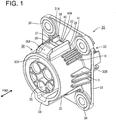
- a vehicle-side connector 10 of this embodiment includes one or more, particularly a plurality of (five in this embodiment) vehicle-side terminal fittings 20 and a connector housing 30 made e.g. of synthetic resin.
- This vehicle-side connector 10 is to be fixed to a vehicle B and an unillustrated charging connector is connectable to the connector housing 30 from front.
- the vehicle-side terminal fitting 20 includes a terminal connecting portion 21 (particularly substantially in the form of a round pin) and a wire connecting portion 22 to be connected to an unillustrated wire.
- the terminal connecting portion 21 is to be electrically conductively connected to a charging-side terminal fitting provided in the charging connector when the charging connector is connected to the connector housing 30.
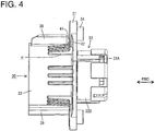
- the connector housing 30 includes a mounting portion 31 (particularly substantially in the form of a substantially rectangular or polygonal flat plate or flange), a (particularly substantially cylindrical or tubular) terminal accommodating portion 32 penetrating through this mounting portion 31 in forward and backward directions FBD, and a (particularly substantially cylindrical or tubular) receptacle (as an example of a "connecting portion") 33 provided at least partly around the terminal accommodating portion 32.
- one or more collars 34 are to be connected (particularly respectively press-fitted) at one or more positions (e.g. at four corners) of the mounting portion 31, and the connector housing 30 is to be fixed to the vehicle by inserting one or more respective fixing bolts V into these one or more collars 34 and tightening them into the vehicle B.
- a seal member such as (particularly substantially annular surface) seal S is to be mounted on (particularly an outer peripheral edge portion of) the terminal accommodating portion 32 between the vehicle B and the rear surface of the mounting portion 31.
- This seal member is to be brought into close contact with the vehicle B and the rear surface of the mounting portion 31, thereby providing fluid- or waterproofing lest fluid or water should enter the terminal accommodating portion 32 through a clearance between the vehicle B and the mounting portion 31.
- the terminal accommodating portion 32 includes a forward projecting portion 32A substantially projecting forward from the mounting portion 31 and/or a backward projecting portion 32B substantially projecting backward from the mounting portion 31. Further, one or more, particularly a plurality of (five in this embodiment) cavities 35 are formed to penetrate through the terminal accommodating portion 32 substantially in forward and backward directions FBD, and the one or more respective vehicle-side terminal fittings 20 are to be held in or positioned or at least partly inserted into the cavities 35.
- the receptacle 33 particularly is at least partly arranged around the forward projecting portion 32A of the terminal accommodating portion 32, and/or substantially extends from a front surface 31A of the mounting portion 31 towards or to the front end surface of the forward projecting portion 32A. That is, the mounting portion 31 particularly is formed to partition between the receptacle 33 and the vehicle B.
- the unillustrated charging connector at least partly is fittable or insertable into the receptacle 33, and a charging-side receptacle provided on the charging connector at least partly is fitted or insertable into a space between the receptacle 33 and the forward projecting portion 32A as the charging connector is fitted into the receptacle 33.
- At least one lock projection (as an example of an "engaging portion") 36 (particularly substantially in the form of a block projecting upward or outward and/or substantially long in forward and backward directions FBD) is provided on (particularly the top or an outside portion of) the receptacle 33.
- this lock projection 36 has an inclined surface 36A directed away from the receptacle 33 toward the back side and/or substantially extends backward from the rear end of this inclined surface 36A and then substantially extends perpendicularly toward the outer surface of the receptacle 33.
- a surface of the lock projection 36 extending toward the outer surface of the receptacle 33 particularly serves as a locking surface 36B, and a locking piece 37 (particularly made of metal) is mounted on this locking surface 36B to at least partly cover a rear part of the lock projection 36.
- a lock claw as an example of a "lock portion" L (particularly made of metal) and provided on the charging connector is pushed up or awy from the receptacle 33 by the inclined surface 36A.
- one or more, particularly a pair of protection walls (as an example of one or more side walls) 38, 38 standing upward from (particularly the upper or distal end of) the receptacle 33 are formed adjacent to the lock projection 36, particularly to substantially face each other on the opposite lateral (left and right) sides of the lock projection 36.
- These one or more, particularly this pair of protection walls 38, 38 substantially extend backward from a position before the lock projection 36 toward the mounting portion 31 located behind and protect the lock projection 36 from external interference in a lateral direction.
- a tip portion L1 of the lock claw L is at least partly accommodated in a recess 40 particularly substantially in a manner enclosed at four sides by the front surface 31 A of the mounting portion 31, the locking surface 36B of the lock projection 36 (locking piece 37), and the inner surfaces of the both protection walls 38, 38 substantially facing each other.
- this recess 40 is open upward or outward or radially, particularly has a substantially rectangular plan view, and is recessed downward or radially inward. Further, the depth of the recess 40 particularly is set to be substantially equal to a projecting distance of the lock projection 36 from the upper end of the receptacle 33, and/or a bottom surface 40A of the recess 40 is located at such a position that the lower end of the tip portion L1 of the lock claw L substantially comes into contact therewith as shown in FIG. 5 .
- At least one positioning recess 39 projecting radially outward (e.g. downward) is provided in (particularly a lower part of) the receptacle 33.
- This positioning recess 39 functions to guide the charging-side receptacle to a proper fitted position by guiding an unillustrated positioning rib provided on the charging-side receptacle of the charging connector thereinto in connecting the charging connector.
- At least one water drainage path 41 is formed adjacent to the protection wall(s) 38, particularly at an end (particularly of each of the pair) of protection wall(s) 38, 38 substantially facing the mounting portion 31 in this embodiment.
- the (particularly both) water drainage path(s) 41, 41 particularly is/are open upward or outward and laterally.
- the (particularly each) water drainage path 41 particularly is defined by the front surface 31 A of the mounting portion 31, the rear end surface of the protection wall 38 and the outer surface of the receptacle 33, and/or particularly formed substantially over the entire height of the protection wall 38. That specifically is, the both protection walls 38, 38 and the mounting portion 31 forming the recess 40 substantially are positioned across the water drainage paths 41 from each other.
- At least one recessed groove 42 slightly lower than the bottom surface 40A of the recess 40 is formed at or near the water drainage paths 41 and/or an end of the recess 40 facing the mounting portion 31.
- the recessed groove 42 provided in the recess 40 is formed to substantially be straight between the water drainage paths 41, 41, and/or arranged at a position behind the tip portion L1 of the lock claw L and/or before the front surface 31 A of the mounting portion 31 with the lock claw L and/or the locking piece 37 of the lock projection 36 engaged in forward and backward directions FBD.
- the rear end surface(s) of the (both) protection wall(s) 38, 38 particularly is/are arranged at position(s) to be substantially flush with the tip of the lock claw L with the lock claw L and the locking piece 37 of the lock projection 36 engaged in forward and backward directions FBD and/or the lock claw L engaged with the lock projection 36 is protected from external interference in the lateral direction by the (particularly both) protection wall(s) 38, 38.
- the vehicle-side connector 10 of this embodiment is configured as described above. Next, functions and effects thereof are described.
- the vehicle-side connector 10 of this embodiment is to be fixed to the vehicle B particularly in such an upward facing posture that the receptacle 33 and the forward projecting portion 32A are facing somewhat upward.
- the charging connector is connected from front and charging is performed with the vehicle-side connector 10 and the charging connector locked into each other by the lock projection 36 and the lock claw L.
- water having flowed into the recess 40 is collected at the rear side (side facing the mounting portion 31).
- water drainage path(s) 41 particularly is/are provided at the end(s) of the protection wall(s) 38 facing the mounting portion 31 in this embodiment water having flowed into the recess 40 can be discharged without any left in the recess 40, for example, as compared with the case where water drainage paths are formed in central parts of the protection walls 38 in forward and backward directions.
- the at least one recessed groove 42 slightly lower than the bottom surface 40A of the recess 40 particularly is formed at the water drainage paths 41 and the end of the recess 40 facing the mounting portion 31.
- the recessed groove 42 particularly is arranged behind the lock claw L engaged with the lock projection 36 the lock claw L does not touch the water having flowed into the recessed groove 42.
- a vehicle-side connector 10 to be connected to a charging connector in charging a battery of a vehicle includes a receptacle 33 which is connectable to the charging connector, a mounting portion 31 which is provided to partition between the receptacle 33 and a vehicle B and to be fixed to the vehicle B, a recess 40 which is open upward or laterally or outward and provided on the connecting portion 33, particularly on or near the top of the connecting portion 33, and one or more water drainage paths 41 formed in inner surfaces of the recess 40 without penetrating through the mounting portion 31.
Landscapes
- Engineering & Computer Science (AREA)
- Power Engineering (AREA)
- Transportation (AREA)
- Mechanical Engineering (AREA)
- Connector Housings Or Holding Contact Members (AREA)
- Electric Propulsion And Braking For Vehicles (AREA)
Applications Claiming Priority (1)
| Application Number | Priority Date | Filing Date | Title |
|---|---|---|---|
| JP2011083479A JP5679191B2 (ja) | 2011-04-05 | 2011-04-05 | 車両側コネクタ |
Publications (2)
| Publication Number | Publication Date |
|---|---|
| EP2509169A1 true EP2509169A1 (fr) | 2012-10-10 |
| EP2509169B1 EP2509169B1 (fr) | 2017-10-18 |
Family
ID=45887868
Family Applications (1)
| Application Number | Title | Priority Date | Filing Date |
|---|---|---|---|
| EP12001650.6A Not-in-force EP2509169B1 (fr) | 2011-04-05 | 2012-03-09 | Connecteur latéral de véhicule |
Country Status (3)
| Country | Link |
|---|---|
| US (1) | US8597039B2 (fr) |
| EP (1) | EP2509169B1 (fr) |
| JP (1) | JP5679191B2 (fr) |
Cited By (2)
| Publication number | Priority date | Publication date | Assignee | Title |
|---|---|---|---|---|
| CN105073503A (zh) * | 2013-02-20 | 2015-11-18 | 三菱电机株式会社 | 车载用电子控制装置 |
| CN105359346A (zh) * | 2013-07-08 | 2016-02-24 | 泰连德国有限公司 | 用于电动或混合动力车辆的电插塞式连接器和插塞式连接器系统 |
Families Citing this family (32)
| Publication number | Priority date | Publication date | Assignee | Title |
|---|---|---|---|---|
| GB2500017B (en) | 2012-03-06 | 2015-07-29 | Dyson Technology Ltd | A Humidifying Apparatus |
| GB2500005B (en) | 2012-03-06 | 2014-08-27 | Dyson Technology Ltd | A method of generating a humid air flow |
| GB2500012B (en) | 2012-03-06 | 2016-07-06 | Dyson Technology Ltd | A Humidifying Apparatus |
| JP5981294B2 (ja) * | 2012-10-12 | 2016-08-31 | 矢崎総業株式会社 | 充電インレット装置 |
| WO2014118501A2 (fr) | 2013-01-29 | 2014-08-07 | Dyson Technology Limited | Ensemble ventilateur |
| JP5862834B2 (ja) | 2013-03-19 | 2016-02-16 | 住友電装株式会社 | 車両側コネクタ |
| US9543713B2 (en) | 2013-03-19 | 2017-01-10 | Sumitomo Wiring Systems, Ltd. | Vehicle-side connector with a relay-circuit unit |
| DE102014003565A1 (de) | 2013-03-19 | 2014-09-25 | Sumitomo Wiring Systems, Ltd. | Fahrzeugseitiger Verbinder und Verfahren zum Zusammenbauen desselben |
| CN105191006B (zh) * | 2013-03-19 | 2017-09-15 | 住友电装株式会社 | 车辆侧连接器 |
| US8986019B2 (en) * | 2013-04-22 | 2015-03-24 | Asm Ip Holding B.V. | Connector with air extraction |
| DE102013218534A1 (de) * | 2013-09-16 | 2015-03-19 | Robert Bosch Gmbh | Akkuladevorrichtung |
| JP6064847B2 (ja) * | 2013-09-17 | 2017-01-25 | 株式会社デンソー | 燃料ポンプ |
| JP2016001522A (ja) | 2014-06-11 | 2016-01-07 | 住友電装株式会社 | 充電用インレット |
| GB2528708B (en) * | 2014-07-29 | 2016-06-29 | Dyson Technology Ltd | A fan assembly |
| DE102014015148B4 (de) * | 2014-10-13 | 2018-11-29 | Sumitomo Wiring Systems, Ltd. | Ladeverbinder und Verfahren zum Montieren desselben |
| JP2016149222A (ja) * | 2015-02-10 | 2016-08-18 | 株式会社フジクラ | コネクタ |
| JP6270785B2 (ja) * | 2015-07-22 | 2018-01-31 | 矢崎総業株式会社 | コネクタ嵌合構造 |
| JP6457919B2 (ja) * | 2015-11-20 | 2019-01-23 | モレックス エルエルシー | コネクタ |
| US9819116B1 (en) | 2016-05-06 | 2017-11-14 | Honda Motor Co., Ltd. | Electrical outlet assembly for a vehicle and methods of assembling same |
| JP6434938B2 (ja) * | 2016-08-10 | 2018-12-05 | 矢崎総業株式会社 | コネクタ |
| CN206441961U (zh) * | 2016-09-21 | 2017-08-25 | 蔚来汽车有限公司 | 电动汽车液冷电池包的连接器 |
| JP6650115B2 (ja) * | 2016-11-02 | 2020-02-19 | 住友電装株式会社 | コネクタ |
| JP2018085172A (ja) * | 2016-11-21 | 2018-05-31 | 住友電装株式会社 | 充電用インレット |
| JP2018085173A (ja) * | 2016-11-21 | 2018-05-31 | 住友電装株式会社 | 充電用インレット |
| JP6490726B2 (ja) * | 2017-02-09 | 2019-03-27 | 矢崎総業株式会社 | 車両側コネクタ |
| CN108879192A (zh) * | 2017-05-12 | 2018-11-23 | 泰科电子(上海)有限公司 | 插座壳体及插座 |
| CN207052838U (zh) * | 2017-05-12 | 2018-02-27 | 泰科电子(上海)有限公司 | 密封件、密封组件及插座 |
| US10608386B2 (en) * | 2018-08-31 | 2020-03-31 | Erich Jaeger Gmbh + Co. Kg | Socket for connecting a trailer plug connector |
| JP6923500B2 (ja) * | 2018-11-09 | 2021-08-18 | 矢崎総業株式会社 | コネクタ |
| JP1634630S (fr) * | 2018-11-28 | 2019-06-24 | ||
| USD931818S1 (en) * | 2020-02-26 | 2021-09-28 | Polestar Performance Ab | Vehicle charge port |
| JP2024068735A (ja) | 2022-11-09 | 2024-05-21 | 矢崎総業株式会社 | コネクタ |
Citations (4)
| Publication number | Priority date | Publication date | Assignee | Title |
|---|---|---|---|---|
| US4793819A (en) * | 1987-02-20 | 1988-12-27 | Sloan Valve Company | Over-the-road vehicle electrical connector with drain passage |
| JPH0729631A (ja) | 1993-07-12 | 1995-01-31 | Sumitomo Wiring Syst Ltd | 電気自動車の充電用コネクタ回りの排水構造 |
| US5800188A (en) * | 1996-02-09 | 1998-09-01 | Joseph Pollak Corporation | Direct connect trailer tow interconnector |
| US20080268706A1 (en) * | 2007-04-28 | 2008-10-30 | Yen-Long Sheng | Waterproof plug for data port of portable electronic device |
Family Cites Families (3)
| Publication number | Priority date | Publication date | Assignee | Title |
|---|---|---|---|---|
| US5458496A (en) | 1993-07-12 | 1995-10-17 | Sumitomo Wiring Systems, Ltd. | Charge coupling for electric vehicle |
| JPH09161882A (ja) * | 1995-12-06 | 1997-06-20 | Yazaki Corp | 電気自動車の充電用コネクタ |
| JPH1064624A (ja) * | 1996-08-20 | 1998-03-06 | Sumitomo Wiring Syst Ltd | コネクタ |
-
2011
- 2011-04-05 JP JP2011083479A patent/JP5679191B2/ja not_active Expired - Fee Related
-
2012
- 2012-03-09 EP EP12001650.6A patent/EP2509169B1/fr not_active Not-in-force
- 2012-03-16 US US13/422,407 patent/US8597039B2/en not_active Expired - Fee Related
Patent Citations (4)
| Publication number | Priority date | Publication date | Assignee | Title |
|---|---|---|---|---|
| US4793819A (en) * | 1987-02-20 | 1988-12-27 | Sloan Valve Company | Over-the-road vehicle electrical connector with drain passage |
| JPH0729631A (ja) | 1993-07-12 | 1995-01-31 | Sumitomo Wiring Syst Ltd | 電気自動車の充電用コネクタ回りの排水構造 |
| US5800188A (en) * | 1996-02-09 | 1998-09-01 | Joseph Pollak Corporation | Direct connect trailer tow interconnector |
| US20080268706A1 (en) * | 2007-04-28 | 2008-10-30 | Yen-Long Sheng | Waterproof plug for data port of portable electronic device |
Cited By (3)
| Publication number | Priority date | Publication date | Assignee | Title |
|---|---|---|---|---|
| CN105073503A (zh) * | 2013-02-20 | 2015-11-18 | 三菱电机株式会社 | 车载用电子控制装置 |
| CN105359346A (zh) * | 2013-07-08 | 2016-02-24 | 泰连德国有限公司 | 用于电动或混合动力车辆的电插塞式连接器和插塞式连接器系统 |
| CN105359346B (zh) * | 2013-07-08 | 2018-09-14 | 泰连德国有限公司 | 用于电动或混合动力车辆的电插塞式连接器和插塞式连接器系统 |
Also Published As
| Publication number | Publication date |
|---|---|
| JP2012221612A (ja) | 2012-11-12 |
| US8597039B2 (en) | 2013-12-03 |
| JP5679191B2 (ja) | 2015-03-04 |
| US20120258617A1 (en) | 2012-10-11 |
| EP2509169B1 (fr) | 2017-10-18 |
Similar Documents
| Publication | Publication Date | Title |
|---|---|---|
| EP2509169A1 (fr) | Connecteur latéral de véhicule | |
| EP2509165B1 (fr) | Connecteur latéral de véhicule | |
| US8257101B2 (en) | Vehicle-side connector | |
| US9478899B2 (en) | Liquidproof connector | |
| EP2626955B1 (fr) | Connecteur de chargement | |
| US8662910B2 (en) | Vehicle-side connector | |
| US9331462B2 (en) | Junction box | |
| US8747129B2 (en) | Charging connector and method of mounting it | |
| US9438018B2 (en) | Junction box | |
| US10770829B2 (en) | Connector | |
| US10594071B2 (en) | Charging inlet with a drainage port in a peripheral wall | |
| US10181676B2 (en) | Male connector | |
| US10355388B2 (en) | Connector | |
| CN107069596A (zh) | 保护器 | |
| US20160315421A1 (en) | Wire harness protector having grounding function | |
| EP3376606B1 (fr) | Connecteur de faisceau de câble | |
| CN108140981B (zh) | 连接器 | |
| JP2010009875A (ja) | 電線カバー付きコネクタ | |
| US20170170599A1 (en) | Connector | |
| US20210265774A1 (en) | Wire cover and connector with wire cover | |
| JP5229186B2 (ja) | 機器用コネクタ | |
| JP6103387B2 (ja) | 保護ケース | |
| JP2016219306A (ja) | 充電インレット | |
| JP2011234609A (ja) | 電線保護ケース |
Legal Events
| Date | Code | Title | Description |
|---|---|---|---|
| PUAI | Public reference made under article 153(3) epc to a published international application that has entered the european phase |
Free format text: ORIGINAL CODE: 0009012 |
|
| AK | Designated contracting states |
Kind code of ref document: A1 Designated state(s): AL AT BE BG CH CY CZ DE DK EE ES FI FR GB GR HR HU IE IS IT LI LT LU LV MC MK MT NL NO PL PT RO RS SE SI SK SM TR |
|
| AX | Request for extension of the european patent |
Extension state: BA ME |
|
| 17P | Request for examination filed |
Effective date: 20130314 |
|
| 17Q | First examination report despatched |
Effective date: 20150326 |
|
| REG | Reference to a national code |
Ref country code: DE Ref legal event code: R079 Ref document number: 602012038576 Country of ref document: DE Free format text: PREVIOUS MAIN CLASS: H01R0013520000 Ipc: B60L0011180000 |
|
| GRAP | Despatch of communication of intention to grant a patent |
Free format text: ORIGINAL CODE: EPIDOSNIGR1 |
|
| RIC1 | Information provided on ipc code assigned before grant |
Ipc: B60L 11/18 20060101AFI20170214BHEP Ipc: H01R 13/52 20060101ALI20170214BHEP |
|
| INTG | Intention to grant announced |
Effective date: 20170302 |
|
| GRAS | Grant fee paid |
Free format text: ORIGINAL CODE: EPIDOSNIGR3 |
|
| GRAJ | Information related to disapproval of communication of intention to grant by the applicant or resumption of examination proceedings by the epo deleted |
Free format text: ORIGINAL CODE: EPIDOSDIGR1 |
|
| GRAL | Information related to payment of fee for publishing/printing deleted |
Free format text: ORIGINAL CODE: EPIDOSDIGR3 |
|
| INTC | Intention to grant announced (deleted) | ||
| GRAR | Information related to intention to grant a patent recorded |
Free format text: ORIGINAL CODE: EPIDOSNIGR71 |
|
| GRAA | (expected) grant |
Free format text: ORIGINAL CODE: 0009210 |
|
| AK | Designated contracting states |
Kind code of ref document: B1 Designated state(s): AL AT BE BG CH CY CZ DE DK EE ES FI FR GB GR HR HU IE IS IT LI LT LU LV MC MK MT NL NO PL PT RO RS SE SI SK SM TR |
|
| INTG | Intention to grant announced |
Effective date: 20170912 |
|
| REG | Reference to a national code |
Ref country code: GB Ref legal event code: FG4D |
|
| REG | Reference to a national code |
Ref country code: CH Ref legal event code: EP |
|
| REG | Reference to a national code |
Ref country code: AT Ref legal event code: REF Ref document number: 937613 Country of ref document: AT Kind code of ref document: T Effective date: 20171115 Ref country code: IE Ref legal event code: FG4D |
|
| REG | Reference to a national code |
Ref country code: DE Ref legal event code: R096 Ref document number: 602012038576 Country of ref document: DE |
|
| REG | Reference to a national code |
Ref country code: NL Ref legal event code: MP Effective date: 20171018 |
|
| REG | Reference to a national code |
Ref country code: LT Ref legal event code: MG4D |
|
| REG | Reference to a national code |
Ref country code: AT Ref legal event code: MK05 Ref document number: 937613 Country of ref document: AT Kind code of ref document: T Effective date: 20171018 |
|
| PG25 | Lapsed in a contracting state [announced via postgrant information from national office to epo] |
Ref country code: NL Free format text: LAPSE BECAUSE OF FAILURE TO SUBMIT A TRANSLATION OF THE DESCRIPTION OR TO PAY THE FEE WITHIN THE PRESCRIBED TIME-LIMIT Effective date: 20171018 |
|
| PG25 | Lapsed in a contracting state [announced via postgrant information from national office to epo] |
Ref country code: NO Free format text: LAPSE BECAUSE OF FAILURE TO SUBMIT A TRANSLATION OF THE DESCRIPTION OR TO PAY THE FEE WITHIN THE PRESCRIBED TIME-LIMIT Effective date: 20180118 Ref country code: LT Free format text: LAPSE BECAUSE OF FAILURE TO SUBMIT A TRANSLATION OF THE DESCRIPTION OR TO PAY THE FEE WITHIN THE PRESCRIBED TIME-LIMIT Effective date: 20171018 Ref country code: ES Free format text: LAPSE BECAUSE OF FAILURE TO SUBMIT A TRANSLATION OF THE DESCRIPTION OR TO PAY THE FEE WITHIN THE PRESCRIBED TIME-LIMIT Effective date: 20171018 Ref country code: FI Free format text: LAPSE BECAUSE OF FAILURE TO SUBMIT A TRANSLATION OF THE DESCRIPTION OR TO PAY THE FEE WITHIN THE PRESCRIBED TIME-LIMIT Effective date: 20171018 Ref country code: SE Free format text: LAPSE BECAUSE OF FAILURE TO SUBMIT A TRANSLATION OF THE DESCRIPTION OR TO PAY THE FEE WITHIN THE PRESCRIBED TIME-LIMIT Effective date: 20171018 |
|
| PG25 | Lapsed in a contracting state [announced via postgrant information from national office to epo] |
Ref country code: HR Free format text: LAPSE BECAUSE OF FAILURE TO SUBMIT A TRANSLATION OF THE DESCRIPTION OR TO PAY THE FEE WITHIN THE PRESCRIBED TIME-LIMIT Effective date: 20171018 Ref country code: AT Free format text: LAPSE BECAUSE OF FAILURE TO SUBMIT A TRANSLATION OF THE DESCRIPTION OR TO PAY THE FEE WITHIN THE PRESCRIBED TIME-LIMIT Effective date: 20171018 Ref country code: LV Free format text: LAPSE BECAUSE OF FAILURE TO SUBMIT A TRANSLATION OF THE DESCRIPTION OR TO PAY THE FEE WITHIN THE PRESCRIBED TIME-LIMIT Effective date: 20171018 Ref country code: GR Free format text: LAPSE BECAUSE OF FAILURE TO SUBMIT A TRANSLATION OF THE DESCRIPTION OR TO PAY THE FEE WITHIN THE PRESCRIBED TIME-LIMIT Effective date: 20180119 Ref country code: RS Free format text: LAPSE BECAUSE OF FAILURE TO SUBMIT A TRANSLATION OF THE DESCRIPTION OR TO PAY THE FEE WITHIN THE PRESCRIBED TIME-LIMIT Effective date: 20171018 Ref country code: BG Free format text: LAPSE BECAUSE OF FAILURE TO SUBMIT A TRANSLATION OF THE DESCRIPTION OR TO PAY THE FEE WITHIN THE PRESCRIBED TIME-LIMIT Effective date: 20180118 Ref country code: IS Free format text: LAPSE BECAUSE OF FAILURE TO SUBMIT A TRANSLATION OF THE DESCRIPTION OR TO PAY THE FEE WITHIN THE PRESCRIBED TIME-LIMIT Effective date: 20180218 |
|
| REG | Reference to a national code |
Ref country code: DE Ref legal event code: R097 Ref document number: 602012038576 Country of ref document: DE |
|
| PG25 | Lapsed in a contracting state [announced via postgrant information from national office to epo] |
Ref country code: EE Free format text: LAPSE BECAUSE OF FAILURE TO SUBMIT A TRANSLATION OF THE DESCRIPTION OR TO PAY THE FEE WITHIN THE PRESCRIBED TIME-LIMIT Effective date: 20171018 Ref country code: CZ Free format text: LAPSE BECAUSE OF FAILURE TO SUBMIT A TRANSLATION OF THE DESCRIPTION OR TO PAY THE FEE WITHIN THE PRESCRIBED TIME-LIMIT Effective date: 20171018 Ref country code: DK Free format text: LAPSE BECAUSE OF FAILURE TO SUBMIT A TRANSLATION OF THE DESCRIPTION OR TO PAY THE FEE WITHIN THE PRESCRIBED TIME-LIMIT Effective date: 20171018 Ref country code: SK Free format text: LAPSE BECAUSE OF FAILURE TO SUBMIT A TRANSLATION OF THE DESCRIPTION OR TO PAY THE FEE WITHIN THE PRESCRIBED TIME-LIMIT Effective date: 20171018 |
|
| PLBE | No opposition filed within time limit |
Free format text: ORIGINAL CODE: 0009261 |
|
| STAA | Information on the status of an ep patent application or granted ep patent |
Free format text: STATUS: NO OPPOSITION FILED WITHIN TIME LIMIT |
|
| PG25 | Lapsed in a contracting state [announced via postgrant information from national office to epo] |
Ref country code: SM Free format text: LAPSE BECAUSE OF FAILURE TO SUBMIT A TRANSLATION OF THE DESCRIPTION OR TO PAY THE FEE WITHIN THE PRESCRIBED TIME-LIMIT Effective date: 20171018 Ref country code: PL Free format text: LAPSE BECAUSE OF FAILURE TO SUBMIT A TRANSLATION OF THE DESCRIPTION OR TO PAY THE FEE WITHIN THE PRESCRIBED TIME-LIMIT Effective date: 20171018 Ref country code: RO Free format text: LAPSE BECAUSE OF FAILURE TO SUBMIT A TRANSLATION OF THE DESCRIPTION OR TO PAY THE FEE WITHIN THE PRESCRIBED TIME-LIMIT Effective date: 20171018 Ref country code: IT Free format text: LAPSE BECAUSE OF FAILURE TO SUBMIT A TRANSLATION OF THE DESCRIPTION OR TO PAY THE FEE WITHIN THE PRESCRIBED TIME-LIMIT Effective date: 20171018 |
|
| 26N | No opposition filed |
Effective date: 20180719 |
|
| REG | Reference to a national code |
Ref country code: CH Ref legal event code: PL |
|
| GBPC | Gb: european patent ceased through non-payment of renewal fee |
Effective date: 20180309 |
|
| PG25 | Lapsed in a contracting state [announced via postgrant information from national office to epo] |
Ref country code: SI Free format text: LAPSE BECAUSE OF FAILURE TO SUBMIT A TRANSLATION OF THE DESCRIPTION OR TO PAY THE FEE WITHIN THE PRESCRIBED TIME-LIMIT Effective date: 20171018 Ref country code: MC Free format text: LAPSE BECAUSE OF FAILURE TO SUBMIT A TRANSLATION OF THE DESCRIPTION OR TO PAY THE FEE WITHIN THE PRESCRIBED TIME-LIMIT Effective date: 20171018 |
|
| REG | Reference to a national code |
Ref country code: BE Ref legal event code: MM Effective date: 20180331 |
|
| REG | Reference to a national code |
Ref country code: IE Ref legal event code: MM4A |
|
| PG25 | Lapsed in a contracting state [announced via postgrant information from national office to epo] |
Ref country code: LU Free format text: LAPSE BECAUSE OF NON-PAYMENT OF DUE FEES Effective date: 20180309 |
|
| REG | Reference to a national code |
Ref country code: DE Ref legal event code: R079 Ref document number: 602012038576 Country of ref document: DE Free format text: PREVIOUS MAIN CLASS: B60L0011180000 Ipc: B60L0050500000 |
|
| PG25 | Lapsed in a contracting state [announced via postgrant information from national office to epo] |
Ref country code: IE Free format text: LAPSE BECAUSE OF NON-PAYMENT OF DUE FEES Effective date: 20180309 |
|
| PG25 | Lapsed in a contracting state [announced via postgrant information from national office to epo] |
Ref country code: CH Free format text: LAPSE BECAUSE OF NON-PAYMENT OF DUE FEES Effective date: 20180331 Ref country code: LI Free format text: LAPSE BECAUSE OF NON-PAYMENT OF DUE FEES Effective date: 20180331 Ref country code: BE Free format text: LAPSE BECAUSE OF NON-PAYMENT OF DUE FEES Effective date: 20180331 Ref country code: GB Free format text: LAPSE BECAUSE OF NON-PAYMENT OF DUE FEES Effective date: 20180309 |
|
| PG25 | Lapsed in a contracting state [announced via postgrant information from national office to epo] |
Ref country code: FR Free format text: LAPSE BECAUSE OF NON-PAYMENT OF DUE FEES Effective date: 20180331 |
|
| PG25 | Lapsed in a contracting state [announced via postgrant information from national office to epo] |
Ref country code: MT Free format text: LAPSE BECAUSE OF NON-PAYMENT OF DUE FEES Effective date: 20180309 |
|
| PG25 | Lapsed in a contracting state [announced via postgrant information from national office to epo] |
Ref country code: TR Free format text: LAPSE BECAUSE OF FAILURE TO SUBMIT A TRANSLATION OF THE DESCRIPTION OR TO PAY THE FEE WITHIN THE PRESCRIBED TIME-LIMIT Effective date: 20171018 |
|
| PGFP | Annual fee paid to national office [announced via postgrant information from national office to epo] |
Ref country code: DE Payment date: 20200225 Year of fee payment: 9 |
|
| PG25 | Lapsed in a contracting state [announced via postgrant information from national office to epo] |
Ref country code: PT Free format text: LAPSE BECAUSE OF FAILURE TO SUBMIT A TRANSLATION OF THE DESCRIPTION OR TO PAY THE FEE WITHIN THE PRESCRIBED TIME-LIMIT Effective date: 20171018 Ref country code: HU Free format text: LAPSE BECAUSE OF FAILURE TO SUBMIT A TRANSLATION OF THE DESCRIPTION OR TO PAY THE FEE WITHIN THE PRESCRIBED TIME-LIMIT; INVALID AB INITIO Effective date: 20120309 |
|
| PG25 | Lapsed in a contracting state [announced via postgrant information from national office to epo] |
Ref country code: CY Free format text: LAPSE BECAUSE OF FAILURE TO SUBMIT A TRANSLATION OF THE DESCRIPTION OR TO PAY THE FEE WITHIN THE PRESCRIBED TIME-LIMIT Effective date: 20171018 Ref country code: MK Free format text: LAPSE BECAUSE OF NON-PAYMENT OF DUE FEES Effective date: 20171018 |
|
| PG25 | Lapsed in a contracting state [announced via postgrant information from national office to epo] |
Ref country code: AL Free format text: LAPSE BECAUSE OF FAILURE TO SUBMIT A TRANSLATION OF THE DESCRIPTION OR TO PAY THE FEE WITHIN THE PRESCRIBED TIME-LIMIT Effective date: 20171018 |
|
| REG | Reference to a national code |
Ref country code: DE Ref legal event code: R119 Ref document number: 602012038576 Country of ref document: DE |
|
| PG25 | Lapsed in a contracting state [announced via postgrant information from national office to epo] |
Ref country code: DE Free format text: LAPSE BECAUSE OF NON-PAYMENT OF DUE FEES Effective date: 20211001 |