EP2505967B1 - Method, System and Device of Phase Identification Using a Smart Meter - Google Patents
Method, System and Device of Phase Identification Using a Smart Meter Download PDFInfo
- Publication number
- EP2505967B1 EP2505967B1 EP12161900.1A EP12161900A EP2505967B1 EP 2505967 B1 EP2505967 B1 EP 2505967B1 EP 12161900 A EP12161900 A EP 12161900A EP 2505967 B1 EP2505967 B1 EP 2505967B1
- Authority
- EP
- European Patent Office
- Prior art keywords
- phase
- meter
- poly
- electrical system
- memory
- Prior art date
- Legal status (The legal status is an assumption and is not a legal conclusion. Google has not performed a legal analysis and makes no representation as to the accuracy of the status listed.)
- Active
Links
- 238000000034 method Methods 0.000 title claims description 45
- 230000015654 memory Effects 0.000 claims description 85
- 238000004891 communication Methods 0.000 claims description 19
- 238000003860 storage Methods 0.000 description 23
- 238000009826 distribution Methods 0.000 description 21
- 230000006870 function Effects 0.000 description 20
- 238000010586 diagram Methods 0.000 description 15
- 230000007246 mechanism Effects 0.000 description 14
- 238000012545 processing Methods 0.000 description 10
- 238000004590 computer program Methods 0.000 description 7
- 239000004020 conductor Substances 0.000 description 6
- 230000007935 neutral effect Effects 0.000 description 6
- 230000003287 optical effect Effects 0.000 description 6
- 238000013475 authorization Methods 0.000 description 4
- 230000008901 benefit Effects 0.000 description 4
- 238000004458 analytical method Methods 0.000 description 3
- 230000005611 electricity Effects 0.000 description 3
- 238000004519 manufacturing process Methods 0.000 description 3
- 230000002093 peripheral effect Effects 0.000 description 3
- 230000008569 process Effects 0.000 description 3
- 230000004044 response Effects 0.000 description 3
- 238000013528 artificial neural network Methods 0.000 description 2
- 230000005540 biological transmission Effects 0.000 description 2
- 230000008859 change Effects 0.000 description 2
- 230000008878 coupling Effects 0.000 description 2
- 238000010168 coupling process Methods 0.000 description 2
- 238000005859 coupling reaction Methods 0.000 description 2
- 238000005516 engineering process Methods 0.000 description 2
- 238000001914 filtration Methods 0.000 description 2
- 238000005259 measurement Methods 0.000 description 2
- 238000012986 modification Methods 0.000 description 2
- 230000004048 modification Effects 0.000 description 2
- 238000013439 planning Methods 0.000 description 2
- 230000001131 transforming effect Effects 0.000 description 2
- XLYOFNOQVPJJNP-UHFFFAOYSA-N water Substances O XLYOFNOQVPJJNP-UHFFFAOYSA-N 0.000 description 2
- 240000005020 Acaciella glauca Species 0.000 description 1
- 208000015976 Corneal dystrophy-perceptive deafness syndrome Diseases 0.000 description 1
- 238000004378 air conditioning Methods 0.000 description 1
- 238000013473 artificial intelligence Methods 0.000 description 1
- 230000006399 behavior Effects 0.000 description 1
- 230000001413 cellular effect Effects 0.000 description 1
- 238000013523 data management Methods 0.000 description 1
- 230000000694 effects Effects 0.000 description 1
- 230000002068 genetic effect Effects 0.000 description 1
- 230000003993 interaction Effects 0.000 description 1
- 239000004973 liquid crystal related substance Substances 0.000 description 1
- 238000010801 machine learning Methods 0.000 description 1
- 230000005055 memory storage Effects 0.000 description 1
- 239000000203 mixture Substances 0.000 description 1
- 230000005405 multipole Effects 0.000 description 1
- 230000006855 networking Effects 0.000 description 1
- 230000008520 organization Effects 0.000 description 1
- 235000003499 redwood Nutrition 0.000 description 1
- 230000009182 swimming Effects 0.000 description 1
- 238000010189 synthetic method Methods 0.000 description 1
- 238000012546 transfer Methods 0.000 description 1
- 238000012384 transportation and delivery Methods 0.000 description 1
- 230000000007 visual effect Effects 0.000 description 1
Images


Classifications
-
- G—PHYSICS
- G01—MEASURING; TESTING
- G01D—MEASURING NOT SPECIALLY ADAPTED FOR A SPECIFIC VARIABLE; ARRANGEMENTS FOR MEASURING TWO OR MORE VARIABLES NOT COVERED IN A SINGLE OTHER SUBCLASS; TARIFF METERING APPARATUS; MEASURING OR TESTING NOT OTHERWISE PROVIDED FOR
- G01D4/00—Tariff metering apparatus
- G01D4/002—Remote reading of utility meters
-
- G—PHYSICS
- G01—MEASURING; TESTING
- G01R—MEASURING ELECTRIC VARIABLES; MEASURING MAGNETIC VARIABLES
- G01R29/00—Arrangements for measuring or indicating electric quantities not covered by groups G01R19/00 - G01R27/00
- G01R29/18—Indicating phase sequence; Indicating synchronism
-
- H—ELECTRICITY
- H02—GENERATION; CONVERSION OR DISTRIBUTION OF ELECTRIC POWER
- H02J—CIRCUIT ARRANGEMENTS OR SYSTEMS FOR SUPPLYING OR DISTRIBUTING ELECTRIC POWER; SYSTEMS FOR STORING ELECTRIC ENERGY
- H02J13/00—Circuit arrangements for providing remote indication of network conditions, e.g. an instantaneous record of the open or closed condition of each circuitbreaker in the network; Circuit arrangements for providing remote control of switching means in a power distribution network, e.g. switching in and out of current consumers by using a pulse code signal carried by the network
- H02J13/00002—Circuit arrangements for providing remote indication of network conditions, e.g. an instantaneous record of the open or closed condition of each circuitbreaker in the network; Circuit arrangements for providing remote control of switching means in a power distribution network, e.g. switching in and out of current consumers by using a pulse code signal carried by the network characterised by monitoring
-
- H—ELECTRICITY
- H02—GENERATION; CONVERSION OR DISTRIBUTION OF ELECTRIC POWER
- H02J—CIRCUIT ARRANGEMENTS OR SYSTEMS FOR SUPPLYING OR DISTRIBUTING ELECTRIC POWER; SYSTEMS FOR STORING ELECTRIC ENERGY
- H02J13/00—Circuit arrangements for providing remote indication of network conditions, e.g. an instantaneous record of the open or closed condition of each circuitbreaker in the network; Circuit arrangements for providing remote control of switching means in a power distribution network, e.g. switching in and out of current consumers by using a pulse code signal carried by the network
- H02J13/00006—Circuit arrangements for providing remote indication of network conditions, e.g. an instantaneous record of the open or closed condition of each circuitbreaker in the network; Circuit arrangements for providing remote control of switching means in a power distribution network, e.g. switching in and out of current consumers by using a pulse code signal carried by the network characterised by information or instructions transport means between the monitoring, controlling or managing units and monitored, controlled or operated power network element or electrical equipment
- H02J13/00012—Circuit arrangements for providing remote indication of network conditions, e.g. an instantaneous record of the open or closed condition of each circuitbreaker in the network; Circuit arrangements for providing remote control of switching means in a power distribution network, e.g. switching in and out of current consumers by using a pulse code signal carried by the network characterised by information or instructions transport means between the monitoring, controlling or managing units and monitored, controlled or operated power network element or electrical equipment using an auxiliary transmission line
-
- H—ELECTRICITY
- H02—GENERATION; CONVERSION OR DISTRIBUTION OF ELECTRIC POWER
- H02J—CIRCUIT ARRANGEMENTS OR SYSTEMS FOR SUPPLYING OR DISTRIBUTING ELECTRIC POWER; SYSTEMS FOR STORING ELECTRIC ENERGY
- H02J3/00—Circuit arrangements for ac mains or ac distribution networks
- H02J3/26—Arrangements for eliminating or reducing asymmetry in polyphase networks
-
- Y—GENERAL TAGGING OF NEW TECHNOLOGICAL DEVELOPMENTS; GENERAL TAGGING OF CROSS-SECTIONAL TECHNOLOGIES SPANNING OVER SEVERAL SECTIONS OF THE IPC; TECHNICAL SUBJECTS COVERED BY FORMER USPC CROSS-REFERENCE ART COLLECTIONS [XRACs] AND DIGESTS
- Y02—TECHNOLOGIES OR APPLICATIONS FOR MITIGATION OR ADAPTATION AGAINST CLIMATE CHANGE
- Y02B—CLIMATE CHANGE MITIGATION TECHNOLOGIES RELATED TO BUILDINGS, e.g. HOUSING, HOUSE APPLIANCES OR RELATED END-USER APPLICATIONS
- Y02B90/00—Enabling technologies or technologies with a potential or indirect contribution to GHG emissions mitigation
- Y02B90/20—Smart grids as enabling technology in buildings sector
-
- Y—GENERAL TAGGING OF NEW TECHNOLOGICAL DEVELOPMENTS; GENERAL TAGGING OF CROSS-SECTIONAL TECHNOLOGIES SPANNING OVER SEVERAL SECTIONS OF THE IPC; TECHNICAL SUBJECTS COVERED BY FORMER USPC CROSS-REFERENCE ART COLLECTIONS [XRACs] AND DIGESTS
- Y02—TECHNOLOGIES OR APPLICATIONS FOR MITIGATION OR ADAPTATION AGAINST CLIMATE CHANGE
- Y02E—REDUCTION OF GREENHOUSE GAS [GHG] EMISSIONS, RELATED TO ENERGY GENERATION, TRANSMISSION OR DISTRIBUTION
- Y02E40/00—Technologies for an efficient electrical power generation, transmission or distribution
- Y02E40/50—Arrangements for eliminating or reducing asymmetry in polyphase networks
-
- Y—GENERAL TAGGING OF NEW TECHNOLOGICAL DEVELOPMENTS; GENERAL TAGGING OF CROSS-SECTIONAL TECHNOLOGIES SPANNING OVER SEVERAL SECTIONS OF THE IPC; TECHNICAL SUBJECTS COVERED BY FORMER USPC CROSS-REFERENCE ART COLLECTIONS [XRACs] AND DIGESTS
- Y02—TECHNOLOGIES OR APPLICATIONS FOR MITIGATION OR ADAPTATION AGAINST CLIMATE CHANGE
- Y02E—REDUCTION OF GREENHOUSE GAS [GHG] EMISSIONS, RELATED TO ENERGY GENERATION, TRANSMISSION OR DISTRIBUTION
- Y02E60/00—Enabling technologies; Technologies with a potential or indirect contribution to GHG emissions mitigation
-
- Y—GENERAL TAGGING OF NEW TECHNOLOGICAL DEVELOPMENTS; GENERAL TAGGING OF CROSS-SECTIONAL TECHNOLOGIES SPANNING OVER SEVERAL SECTIONS OF THE IPC; TECHNICAL SUBJECTS COVERED BY FORMER USPC CROSS-REFERENCE ART COLLECTIONS [XRACs] AND DIGESTS
- Y04—INFORMATION OR COMMUNICATION TECHNOLOGIES HAVING AN IMPACT ON OTHER TECHNOLOGY AREAS
- Y04S—SYSTEMS INTEGRATING TECHNOLOGIES RELATED TO POWER NETWORK OPERATION, COMMUNICATION OR INFORMATION TECHNOLOGIES FOR IMPROVING THE ELECTRICAL POWER GENERATION, TRANSMISSION, DISTRIBUTION, MANAGEMENT OR USAGE, i.e. SMART GRIDS
- Y04S10/00—Systems supporting electrical power generation, transmission or distribution
- Y04S10/30—State monitoring, e.g. fault, temperature monitoring, insulator monitoring, corona discharge
-
- Y—GENERAL TAGGING OF NEW TECHNOLOGICAL DEVELOPMENTS; GENERAL TAGGING OF CROSS-SECTIONAL TECHNOLOGIES SPANNING OVER SEVERAL SECTIONS OF THE IPC; TECHNICAL SUBJECTS COVERED BY FORMER USPC CROSS-REFERENCE ART COLLECTIONS [XRACs] AND DIGESTS
- Y04—INFORMATION OR COMMUNICATION TECHNOLOGIES HAVING AN IMPACT ON OTHER TECHNOLOGY AREAS
- Y04S—SYSTEMS INTEGRATING TECHNOLOGIES RELATED TO POWER NETWORK OPERATION, COMMUNICATION OR INFORMATION TECHNOLOGIES FOR IMPROVING THE ELECTRICAL POWER GENERATION, TRANSMISSION, DISTRIBUTION, MANAGEMENT OR USAGE, i.e. SMART GRIDS
- Y04S20/00—Management or operation of end-user stationary applications or the last stages of power distribution; Controlling, monitoring or operating thereof
- Y04S20/30—Smart metering, e.g. specially adapted for remote reading
Definitions
- utility providers desire to electronically communicate with the utility service meters for numerous purposes including scheduling disconnection or connection of utility services to the metered loads, automatic meter reading (AMR), load shedding and load control, automatic distribution and smart-grid applications, outage reporting, providing additional services such as Internet, video, and audio, etc.
- AMR automatic meter reading
- load shedding and load control load shedding and load control
- smart-grid applications outage reporting
- additional services such as Internet, video, and audio, etc.
- the meters must be configured to communicate with one or more computing devices through a communications network, which can be wired, wireless or a combination of wired and wireless, as known to one of ordinary skill in the art.
- such meters are also equipped with an electromechanical switch that can be actuated remotely to perform functions such as disconnection or connection of utility services to the metered loads, load shedding and load control, and the like.
- the utility also desires to know which phase or phases of a poly-phase electrical system the load is connected, or which phase or phases a load control relay is connected.
- One challenge faced by the utilities is that the records are incomplete or inaccurate that indicate to a smart meter installer which phase an individual customer is connected. Therefore, in order to accurately identify the current phase of a particular feeder branch, utility company personnel must physically trace a cable run back through various distribution facilities until they reach a point in the distribution network at which the phase is defmitively known.
- WO-A-2010/089396 concerns a smart metering device with phase selector.
- the device receives control messages from a communication server associated with a power distribution network, to control a phase switching operation which is done under no-load conditions.
- US-A-2010/262393 concerns a system and method for determining one of a plurality of power line phase conductors to which a remote device is electrically connected.
- a transmission device transmits a phase identifier message at a zero crossing of a phase voltage, which may be used by a receiving device to determine if the message was sent on the phase to which it is connected.
- the phase identifier message includes a control code and a phase code, which is stored in memory in the transmission device.
- the present invention provides a method of phase identification as defined in appended claim 1 and a meter as defined in appended claim 6.
- Described herein are embodiments of methods, devices and systems for phase identification of a smart meter.
- One aspect comprises a method of phase identification for a smart meter.
- One embodiment of the method comprises connecting a device to at least a first phase of a poly-phase electrical system; metering at least the first phase of the poly-phase electrical system that the device is connected to for electrical consumption information using a smart meter; storing a first phase identifier for the first phase of the poly-phase electrical system that the device is connected to in a memory associated with the smart meter; and transmitting at least the first phase identifier over a network operably connected with the smart meter.
- Another aspect comprises a smart meter.
- One embodiment of the smart meter is comprised of one or more switches, metering components, a memory, at least one network interface, and a processor.
- the one or more switches can be used to connect a device to at least a first phase of a poly-phase electrical system.
- the metering components can be used to meter at least the first phase of the poly-phase electrical system that the device is connected to for electrical consumption information.
- the processor is operably connected with the one or more switches, the metering components, the memory and the at least one network interface.
- the processor is configured to: store a first phase identifier for the first phase of the poly-phase electrical system that the device is connected to in the memory; and retrieve the first phase identifier for the first phase of the poly-phase electrical system that the device is connected to from the memory and transmit at least the first phase identifier over a network operably connected with the smart meter using the network interface.
- a system is described.
- One embodiment of the system is comprised of a computing device, a network operably connected to the computing device, and a smart meter operably connected with the network.
- the smart meter is comprised of one or more switches, metering components, a memory, at least one network interface, and a processor.
- the one or more switches can be used to connect a device to at least a first phase of a poly-phase electrical system.
- the metering components can be used to meter at least the first phase of the poly-phase electrical system that the device is connected to for electrical consumption information.
- the processor is operably connected with the one or more switches, the metering components, the memory and the at least one network interface.
- the processor is configured to: store a first phase identifier for the first phase of the poly-phase electrical system that the device is connected to in the memory; and retrieve the first phase identifier for the first phase of the poly-phase electrical system that the device is connected to from the memory and transmit at least the first phase identifier over a network operably connected with the smart meter using the network interface.
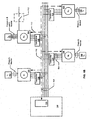
- FIG. 1A is a single-line block diagram of a section of an exemplary utility distribution system such as, for example, an electric distribution system.
- a utility service is delivered by a utility provider 100 to various loads L 1 -L n 102 through a distribution system 104.
- the utility service provided can be electric power.
- the distribution system 104 can be comprised of single-phase and/or poly-phase components and be of varying voltage levels.
- the meters 106 can be single-phase or poly-phase electric meters, as known to one of ordinary skill in the art, depending upon the load 102.
- the load can be single-phase and therefore the meter 106 can be single phase.
- Single-phase loads can be connected to different phases (e.g., phase A, phase B or phase C) of the distribution system 104.
- the load 102 can be a poly-phase load such as a three-phase load and the meter 106 can be a three-phase meter that meters the three phases serving the load 102.
- the electric meter 106 is a smart meter as described herein and as known to one of ordinary skill in the art.
- the specification will refer to the meter 106 as a "meter,” “electric meter,” and/or “smart meter,” where the terms can be used interchangeably.
- a smart meter is the GE I210+c meter as available from General Electric Company (“GE”) (Schenectady, NY).
- GE General Electric Company
- Another non-limiting example of a smart meter is the GE SM3000 meter as also available from GE. While consumption or demand information is used by the utility provider 100 primarily for billing the consumer, it also can be used for other purposes including planning and profiling the utility distribution system.
- utility providers 100 desire to electronically communicate with the meters 106 for numerous purposes including scheduling disconnection or connection of utility services to the loads 102, automatic meter reading (AMR), load shedding and load control, automatic distribution and smart-grid applications, outage reporting, providing additional services such as Internet, video, and audio, etc.
- AMR automatic meter reading
- the meters 106 must be configured to communicate with one or more computing devices 108 through a communications network 110, which can be wired, wireless or a combination of wired and wireless, as known to one of ordinary skill in the art.
- the network 110 is an advanced metering infrastructure (AMI) network.
- AMI advanced metering infrastructure
- AMI refers to systems that measure, collect and analyze energy usage, and interact with advanced devices such as electricity meters, gas meters, water meters, and the like through various communication media either on request (on-demand) or on pre-defined schedules.
- This infrastructure includes hardware, software, communications, consumer energy displays and controllers, customer associated systems, meter data management (MDM) software, supplier and network distribution business systems, and the like.
- MDM meter data management
- the network 110 between the measurement devices (e.g., meters 106) and business systems allows collection and distribution of information to customers, suppliers, utility companies and service providers. This enables these businesses to either participate in, or provide, demand response solutions, products and services.
- the system assists a change in energy usage from their normal consumption patterns, either in response to changes in price or as incentives designed to encourage lower energy usage use at times of peak-demand periods or higher wholesale prices or during periods of low operational systems reliability.
- the network 110 comprises at least a portion of a smart grid network.
- the network 110 utilizes one or more of one or more of a WPAN (e.g., ZigBee, Bluetooth), LAN/WLAN (e.g., 802.11n, microwave, laser, etc.), WMAN (e.g., WiMAX, etc.), WAN/WWAN (e.g., UMTS, GPRS, EDGE, CDMA, GSM, CDPD, Mobitex, HSDPA, HSUPA, 3G, etc.), RS232, USB, Firewire, Ethernet, wireless USB, cellular, OpenHAN, power line carrier (PLC), broadband over power lines (BPL), and the like.
- WPAN e.g., ZigBee, Bluetooth
- LAN/WLAN e.g., 802.11n, microwave, laser, etc.
- WMAN e.g., WiMAX, etc.
- WAN/WWAN e.g., UMTS, GPRS, EDGE, CDMA, GSM, CDPD, Mobitex, H
- an electrical distribution system 104 may be a poly-phase system such as a three-phase, four-wire network, which supplies power-using feeders.
- Each of the feeder lines then branches into multiple circuits to power a plurality of local pole-mounted or pad-mounted transformers, which step the voltage down to final voltages of, for example, 120 or 240 volts per phase for delivery and metering at commercial and residential customer locations.
- residential customers can be connected to any one phase of the three-phase system using a single-phase meter and commercial customers can be connected to all the three phases using three-phase meter with a load control relay ("LCR") connected on any one of the phases.
- LCR load control relay
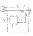
- FIG. 1B is an exemplary illustration of a three-phase, four-wire (phases A, B, C and neutral, N) distribution system 104 according to one embodiment of the present invention.
- distribution system 104 is comprised of three phase conductors (phases A, B and C) and a neutral wire. In one aspect, each of three phases and the neutral are provided to each meter 106.
- the voltage provided at the meters 106 is stepped down by a transformer 114 to a level that can be used by the load 102 (e.g. 120/240, 277/480, and the like).
- the transformer 114 can be two or three single-phase transformers, or a single three-phase transformer.
- the load 102 can be single phase
- the meter 106 can be configured to switch between phases A, B and C to serve the load 102, or to disconnect the load 102 from electric service. In one aspect, this switching can be manually performed. In another aspect, this switching can be performed automatically and remotely.
- the load 102 can be three-phase and can be metered by a three-phase meter 106.
- the three-phase meter can comprise a load control relay (LCR) 112.
- the three-phase meter 106 can be configured to switch between phases A, B and C to serve the LCR 112, or to disconnect the LCR 112 from electric service. In one aspect, this switching can be manually performed. In another aspect, this switching can be performed automatically and remotely. For balancing the load on each phase of the distribution system 104 and performing other utility functions and analysis, it is desired to know the phase that a load 102 is connected or the phase that a LCR 112 is connected.
- a field for phase identification is maintained in a memory of a smart meter.
- the phase identifier can be read or written (depending on security) by a utility using advanced communication techniques such as AMI, Optical, RF, WiMax, LAN/WAN, GSM, etc., and meter software (e.g., GE Meter Mate TM software).
- advanced communication techniques such as AMI, Optical, RF, WiMax, LAN/WAN, GSM, etc.
- meter software e.g., GE Meter Mate TM software.
- this field can represent the phase to which the main relay is connected and in the case of poly-phase meter (e.g., three-phase), this field can represent the phase to which an LCR is connected.
- the phase identification field can be configured to update automatically.
- phase identification field can be provided over the network to the meter if an entire feeder has been switched using, for example, automated distribution switches as part of a smart-grid implementation.
- phase identification field can be stored manually whenever phase configuration as stated above is changed for a particular meter.
- phase identifier field upon receiving a command to switch phases (for example, from phase A to phase B), the phase to which meter is currently connected is read (phase A) and a relay will be switched to phase B and the phase identifier field will be updated from phase A to phase B.
- phase A the phase to which meter is currently connected
- a relay will be switched to phase B and the phase identifier field will be updated from phase A to phase B.
- software for example, GE Meter Mate TM software
- Phase change events can be logged in an event log kept at either or both the meter and the computing device 108 for future reference.
- FIG. 2 illustrates an overview block diagram of a non-limiting embodiment of a meter 106 that can be used to practice embodiments of the present invention.
- the utility service is poly-phase electric power.
- the electric service is three-phase, four-wire electric power generally comprised of three phase conductors 202 each carrying electric voltage and current that is generally displaced from one another by 120 degrees (e.g., phases A, B and C) and a separate neutral wire 214.
- the embodiments of the invention can be used with single- and poly-phase electrical systems such as two-phase, three-phase, four-phase, etc.
- a switch 204 Further comprising the embodiment of a meter 106 shown in FIG. 2 is a switch 204.
- the switch 204 can be a single switch or any combination of single or multi-pole switches that provide a means to selectively switch the power feed 104 that provides electrical service from among the plurality of phase conductors 202 (e.g., phases A, B or C), or to disconnect the load 102 from electrical service.
- the load 102 can be provided with single-phase electrical service from among any of a plurality of phases.
- a meter 106 can be configured to switch among two, three, four, five, etc. phases, and is not limited to just a three-phase configuration to provide single-phase service to the load 102.
- the switch 204 can be controlled by a control mechanism 212 that actuates the switch 204 (i.e., causes it to switch from one phase to another or to disconnect the load).
- the control mechanism 212 receives a control signal from the meter's electronics 206.
- the control mechanism 212 can provide a feedback signal to the meter's electronics 206 that indicates the position of the switch 204. In other words, the control mechanism 212 can inform the meter's electronics whether the load 102 is being provided single-phase electric service from phase A, phase B, phase C, etc., or whether the load 102 is disconnected from electric service.
- Analog voltage and current inputs are also provided to meter electronics 206.
- the analog signals are derived from the electrical power feed 104 serving the load 102 and the one being metered by the meter 106.
- the analog signals are derived from a separate electrical source.
- the analog voltage signal can be provided by one or more potential transformers (PT) 208, if needed, though other means such as a voltage divider, capacitive coupling, or the like can be used. If the voltage level of the source is sufficiently low (e.g., .25 volts AC, or lower), then a PT 208 or other means of stepping down or transforming the voltage can be omitted.
- PT potential transformers
- the analog current signal can be provided by one or more current transformers (CT) 210.
- CT current transformers
- the one or more CTs 210 can have a turns ratio of 1:2500.
- one or more resistors (not shown) can be used to convert the current signal from the CT 210 into a voltage signal.
- the meter electronics 206 can comprise a memory (not shown in FIG. 2 ).
- the memory can be used to store a phase identifier that indicates the phase of the poly-phase electrical system that the load 102 (and meter 106) are connected. For example, if the switch 204 is configured such that the electrical power feed 104 serving the load 102 and the one being metered by the meter 106 is phase A, then the phase identifier stored in the memory indicates phase A. Similarly, if the switch 204 switches from phase A to phase B, then the phase identifier stored in the memory is updated to indicate phase B. In one aspect, the phase identifier is stored automatically when the power feed 104 is switched from one phase to another (e.g., from phase A to phase B).
- the control mechanism 212 can provide a signal that indicates the phase that the load 102 is connected to.
- a signal can be sent to the meter 106 over a network 110.
- the network 110 is an advanced metering infrastructure (AMI) network.
- the signal can be a command to switch phases to which the load is connected from a first phase (e.g., phase A) to a second phase (e.g., phase B), or to disconnect the load 102.
- the command is received by a processor (not shown in FIG. 2 ) in the meter's electronics 206, which causes the control mechanism 212 to switch the connection from phase A to phase B.
- phase identifier in the memory is then updated to reflect that the load 102 and meter 106 are now connected to phase B.
- the phase identifier can be stored in the meter 106 manually by a user that has authorization to write to the memory using, for example, infrared, near-field communications such as BlueTooth, Wi-Fi, RF, RFID, and the like, or by connecting a device such as a computer to the meter 106 using a bus connection.
- the phase identifier can be communicated to the memory in the meter's electronics 206 via a network 110 that is operably connected with the meter's electronics 206.
- the network 110 is an advanced metering infrastructure (AMI) network.
- AMI advanced metering infrastructure
- phase A becomes phase B or some other similar switching
- a signal can be sent to the meter's electronics 206 over the network to update the phase identifier such that indicates the meter 206 and the load 102 are connected to phase B.
- the phase identifier Once the phase identifier is stored in the memory, it can be transmitted over the network 110 to, for example, the computing device 108 or it can be read from the memory by a user with proper authorization and equipment.
- the electronics 206 comprise at least a memory, and one or more processors and provide an interface for receiving a signal from the network 110 and causing the switch 204 to actuate via the control mechanism 212.
- the memory of the meter electronics 206 can be used to store a phase identifier as described above.
- the meter electronics 206 can comprise a transmitter that can be used to transmit at least the phase identifier over the network 110 to a separate computing device 108.
- the meter's electronics 206 can comprise one or more metering microcontrollers including a Teridian 6533 controller or a Teridian 6521 controller as are available from Maxim Integrated Products, Inc. (Sunnyvale, California), among others.
- the one or more processors can perform metering functions such as determining the number of kilowatt-hours (KWH) of electricity consumed by the load 102.
- KWH kilowatt-hours
- the one or more processors of the meter electronics 206 can be configured to store a first phase identifier for the first phase of the poly-phase electrical system that the load 102 is connected to in the memory. Then, when requested, the processor can retrieve the first phase identifier for the first phase of the poly-phase electrical system that the device is connected to from the memory and transmit at least the first phase identifier to the computing device 108 over the network 110 operably connected with the smart meter 106 using the network interface.
- the network 110 is an advanced metering infrastructure (AMI) network.
- AMI advanced metering infrastructure
- the switch 204 can be used to switch the load 102 such that the load is connected to at least a second phase of the poly-phase electrical system such that the metering components meter at least the second phase of the poly-phase electrical system that the load 102 is connected to for electrical consumption information using the smart meter 102.
- the one or more processors are further configured to store a second phase identifier for the second phase of the poly-phase electrical system that the load 102 is connected to in the memory associated with the smart meter 106.
- the one or more processors are also configured to retrieve the second phase identifier for the second phase of the poly-phase electrical system that the load 102 is connected to from the memory and transmit at least the second phase identifier to the computing device 108 over the network 110 operably connected with the smart meter 106 using the network interface.
- the switch 204 is an automatic switch controlled by the processor and switching the load 102 such that the load 102 is connected to at least the second phase of the poly-phase electrical system comprises automatically switching the load 102 from the first phase to the second phase of the poly-phase electrical system using the switch 204.
- the one or more processors are operably connected with the switch 204 such that storing the second phase identifier for the second phase of the poly-phase electrical system that the load 102 is connected to in the memory associated with the smart meter 106 comprises automatically storing the second phase identifier in the memory when the device is switched from the first phase to the second phase of the poly-phase electrical system.
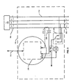
- FIG. 3 illustrates an embodiment of a meter 106 used to meter a poly-phase electrical service 104 serving a load 102.
- the poly-phase electrical service 104 is a three-phase service comprised of phase conductors 202 for phase A, phase B and phase C, and a neutral wire 214. In other embodiments, there can be more or fewer electrical phases and phase conductors.
- switch 204 is used to provide electrical power to a load control relay (LCR) 302.
- the LCR can be used to turn on or off select loads using the meter 106.
- the LCR can be used to turn on or off power to a hot water heater, swimming pool pump or heater, air conditioning equipment, etc.
- the LCR 302 can have a 40-amp rating. In another aspect, the LCR 302 can have a two-amp rating. In one aspect, the LCR 302 can receive control signals from the meter's electronics 206. In another aspect, the LCR 302 can receive control signals external from the meter 106. For example, the LCR 302 can receive a wireless signal causing the LCR 302 to open or close. As shown in FIG. 3 , the switch 204 can be used to connect the LCR to one of phases A, B, or C, or to disconnect it altogether. Though shown as a three-pole, single-throw switch, the switch 204 can be a single switch or a plurality of switches having any number of poles and/or throws.
- the control mechanism 212 of FIG. 3 is used to actuate the switch 204 (i.e., causes it to switch from one phase to another or to disconnect the LCR 302).
- the control mechanism 212 receives a control signal from the meter's electronics 206.
- the control mechanism 212 can provide a feedback signal to the meter's electronics 206 that indicates the position of the switch 204.
- the control mechanism 212 can inform the meter's electronics whether the LCR 302 is being provided single-phase electric service from phase A, phase B, phase C, etc., or whether the LCR 302 is disconnected from electric service.
- the meter electronics 206 can comprise a memory (not shown in FIG. 3 ).
- the memory can be used to store a phase identifier that indicates the phase of the poly-phase electrical system that the LCR 302 is connected. For example, if the switch 204 is configured such that the phase serving the LCR 302 is phase A, then the phase identifier stored in the memory indicates phase A. Similarly, if the switch 204 switches from phase A to phase B, then the phase identifier stored in the memory indicates phase B.
- the phase identifier is stored automatically when the LCR 302 is switched from one phase to another (e.g., from phase A to phase B).
- the control mechanism 212 can provide a signal that indicates the phase that the LCR 302 is connected to.
- a signal can be sent to the meter 106 over a network 110.
- the network 110 is an advanced metering infrastructure (AMI) network.
- the signal can be a command to switch phases to which the LCR 302 is connected from a first phase (e.g., phase A) to a second phase (e.g., phase B), or to disconnect the LCR 302.
- the command is received by a processor (not shown in FIG. 3 ) in the meter's electronics 206, which causes the control mechanism 212 to switch the connection from phase A to phase B.
- phase identifier in the memory is then updated to reflect that the LCR 302 is now connected to phase B.
- the phase identifier can be stored in the meter 106 manually by a user that has authorization to write to the memory using, for example, infrared, near-field communications such as BlueTooth, Wi-Fi, RF, RFID, and the like, or by connecting a device such as a computer to the meter 106 using a bus connection.
- the phase identifier can be communicated to the memory in the meter's electronics 206 via a network 110 that is operably connected with the meter's electronics 206.
- phase A becomes phase B or some other similar switching
- a signal can be sent to the meter's electronics 206 over the network 110 to update the phase identifier such that it indicates the LCR 302 is connected to phase B.
- the phase identifier Once the phase identifier is stored in the memory, it can be transmitted over the network 110 to, for example, the computing device 108 or it can be read from the memory by a user with proper authorization and equipment.
- the electronics 206 comprise at least a memory, and one or more processors and provide an interface for receiving a signal from the network 110 and causing the switch 204 to actuate via the control mechanism 212.
- the memory of the meter electronics 206 can be used to store a phase identifier as described above.
- the meter electronics 206 can comprise a transmitter that can be used to transmit at least the phase identifier over the network 110 to a separate computing device 108.
- the network 110 is an advanced metering infrastructure (AMI) network.
- the meter's electronics 206 can comprise one or more metering microcontrollers including a Teridian 6533 controller or a Teridian 6521 controller as are available from Maxim Integrated Products, Inc.
- the one or more processors can perform metering functions such as determining the number of kilowatt-hours (KWH) of electricity consumed by the load 102.
- Analog voltage and current inputs are also provided to meter electronics 206.
- the analog signals are derived from the electrical power feed 104 serving the load 102 and the one being metered by the meter 106.
- the analog signals are derived from a separate electrical source.
- the analog voltage signal can be provided by one or more potential transformers (PT) 208, if needed, though other means such as a voltage divider, capacitive coupling, or the like can be used.
- PT potential transformers
- the analog current signal can be provided by one or more current transformers (CT) 210.
- CT current transformers
- the one or more CTs 210 can have a turns ratio of 1:2500.
- one or more resistors (not shown) can be used to convert the current signal from the CT 210 into a voltage signal.
- the one or more processors of the meter electronics 206 can be configured to store a first phase identifier for the first phase of the poly-phase electrical system that the LCR 302 is connected to in the memory. Then, when requested, the processor can retrieve the first phase identifier for the first phase of the poly-phase electrical system that the LCR 302 is connected to from the memory and transmit at least the first phase identifier to the computing device 108 over the network 110 operably connected with the smart meter 106 using the network interface.
- the switch 204 can be used to switch the LCR 302 such that the LCR 302 is connected to at least a second phase of the poly-phase electrical system.
- the one or more processors are further configured to store a second phase identifier for the second phase of the poly-phase electrical system that the LCR 302 is connected to in the memory associated with the smart meter 106.
- the one or more processors are also configured to retrieve the second phase identifier for the second phase of the poly-phase electrical system that the LCR 302 is connected to from the memory and transmit at least the second phase identifier to the computing device 108 over the network 110 operably connected with the smart meter 106 using the network interface.
- the switch 204 is an automatic switch controlled by the processor and switching the LCR 302 such that the LCR 302 is connected to at least the second phase of the poly-phase electrical system comprises automatically switching the LCR 302 from the first phase to the second phase of the poly-phase electrical system using the switch 204.
- the one or more processors are operably connected with the switch 204 such that storing the second phase identifier for the second phase of the poly-phase electrical system that the LCR 302 is connected to in the memory associated with the smart meter 106 comprises automatically storing the second phase identifier in the memory when the device is switched from the first phase to the second phase of the poly-phase electrical system.
- FIG. 4 a block diagram of an entity capable of operating as meter electronics 206 is shown in accordance with one embodiment of the present invention.
- the entity capable of operating as a meter electronics 206 includes various means for performing one or more functions in accordance with embodiments of the present invention, including those more particularly shown and described herein. It should be understood, however, that one or more of the entities may include alternative means for performing one or more like functions, without departing from the spirit and scope of the present invention.
- the entity capable of operating as a meter electronics 206 can generally include means, such as one or more processors 404 for performing or controlling the various functions of the entity. As shown in FIG.
- meter electronics 206 can comprise metering components such as meter inputs and filtering components 402.
- the meter inputs and filter components 402 can comprise voltage and current inputs, one or more ADCs, filtering components, and the like.
- the one or more processors 404 are in communication with or include memory 406, such as volatile and/or non-volatile memory that stores content, data or the like.
- the memory 406 may store content transmitted from, and/or received by, the entity.
- the memory 406 may store software applications, instructions or the like for the one or more processors 404 to perform steps associated with operation of the entity in accordance with embodiments of the present invention.
- the one or more processors 404 may be configured to perform the processes discussed in more detail herein for receiving an actuation command for a switch, causing a control associated with the switch to implement the actuation, receiving a phase identifier from the switch, and transmitting the phase identifier to a computing device over a network.
- the one or more processors 404 can be configured to update the phase identifier when a device (e.g., a load or a LCR) is switched from a first phase to a second phase, as described herein.
- a device e.g., a load
- the one or more processors 404 can also be connected to at least one interface or other means for displaying, transmitting and/or receiving data, content or the like.
- the interface(s) can include at least one communication interface 408 or other means for transmitting and/or receiving data, content or the like, as well as at least one user interface that can include a display 410 and/or a user input interface 412.
- the communication interface 408 can be used to transfer a phase identifier stored in the memory 406 to a remote computing device such as the one described below over a network 110.
- the network 110 is an advanced metering infrastructure (AMI) network.
- AMI advanced metering infrastructure
- the communication interface 608 can comprise a wireless communication interface such as a Wi-Fi transceiver.
- the user input interface 412 can comprise any of a number of devices allowing the entity to receive data from a user, such as a keypad, a touch display, a joystick or other input device.
- a device is connected to at least a first phase of a poly-phase electrical system.
- the device is an electrical load.
- the electrical load is a single-phase electrical load.
- the electrical load is a poly-phase electrical load.
- the poly-phase electrical load is a three-phase electrical load.
- the device is a load control relay (LCR).
- LCR load control relay
- a first phase identifier for the first phase of the poly-phase electrical system that the device is connected to is stored in a memory associated with the smart meter.
- at least the first phase identifier is transmitted over a network operably connected with the smart meter.
- the network 110 is an advanced metering infrastructure (AMI) network.
- AMI advanced metering infrastructure
- the operations for phase identification in a smart meter as shown in FIG. 5 can further include the steps illustrated in FIG. 6 .
- the device can be switched such that the device is connected to at least a second phase of the poly-phase electrical system.
- switching the device such that the device is connected to at least the second phase of the poly-phase electrical system comprises automatically switching the device from the first phase to the second phase of the poly-phase electrical system using the smart meter.
- at least the second phase of the poly-phase electrical system that the device is connected to is metered for electrical consumption information using the smart meter.
- a second phase identifier for the second phase of the poly-phase electrical system that the device is connected to is stored in the memory associated with the smart meter.
- storing the second phase identifier for the second phase of the poly-phase electrical system that the device is connected to in the memory associated with the smart meter comprises automatically storing the second phase identifier when the device is switched from the first phase to the second phase of the poly-phase electrical system.
- the second phase identifier is transmitted over the network operably connected with the smart meter.
- FIG. 7 illustrates the operations that can be taken to switch a device from a first phase connection to a second phase connection and to update the phase identifier for the device connection using a computing device such as the one described in reference to FIG. 8 , below.
- a command is issued by a computing device and transmitted to a smart meter. The command is to switch the phase that a device is connected to from a first phase to a second phase using the smart meter.
- the device is an electrical load (either single-phase or poly-phase).
- the device is a load control relay (LCR), either single- or poly-phase.
- LCR load control relay
- a phase identifier for the second phase that the device is connected to is received by the computing device from the smart meter.
- the phase identifier can be an identifier that identifies the phase that the device is connected to as phase A, phase B, Phase C, or the like.
- the phase identifier is stored in the memory of the computing device.
- a unit such as a smart appliance, a smart meter, a smart grid, a utility computing device, a vendor or manufacturer's computing device, etc., can be software, hardware, or a combination of software and hardware.
- the units can comprise the switching software 806 as illustrated in FIG. 8 and described below.
- the units can comprise a computing device 108 as referenced above and further described below.
- FIG. 8 is a block diagram illustrating an exemplary operating environment for performing the disclosed methods.
- This exemplary operating environment is only an example of an operating environment and is not intended to suggest any limitation as to the scope of use or functionality of operating environment architecture. Neither should the operating environment be interpreted as having any dependency or requirement relating to any one or combination of components illustrated in the exemplary operating environment.
- the present methods and systems can be operational with numerous other general purpose or special purpose computing system environments or configurations.
- Examples of well known computing systems, environments, and/or configurations that can be suitable for use with the systems and methods comprise, but are not limited to, personal computers, server computers, laptop devices, and multiprocessor systems. Additional examples comprise set top boxes, programmable consumer electronics, network PCs, minicomputers, mainframe computers, smart meters, smart-grid components, distributed computing environments that comprise any of the above systems or devices, and the like.
- the processing of the disclosed methods and systems can be performed by software components.
- the disclosed systems and methods can be described in the general context of computer-executable instructions, such as program modules, being executed by one or more computers or other devices.
- program modules comprise computer code, routines, programs, objects, components, data structures, etc. that perform particular tasks or implement particular abstract data types.
- the disclosed methods can also be practiced in grid-based and distributed computing environments where tasks are performed by remote processing devices that are linked through a communications network.
- program modules can be located in both local and remote computer storage media including memory storage devices.
- the systems and methods disclosed herein can be implemented via a general-purpose computing device in the form of a computing device 108.
- the components of the computing device 108 can comprise, but are not limited to, one or more processors or processing units 803, a system memory 812, and a system bus 813 that couples various system components including the processor 803 to the system memory 812.
- the system can utilize parallel computing.
- the processor 803 is configured to send an actuation signal to a smart meter and receive a phase identifier from the smart meter in accordance with the electrical phase that the device at the smart meter is connected.
- the system bus 813 represents one or more of several possible types of bus structures, including a memory bus or memory controller, a peripheral bus, an accelerated graphics port, and a processor or local bus using any of a variety of bus architectures.
- bus architectures can comprise an Industry Standard Architecture (ISA) bus, a Micro Channel Architecture (MCA) bus, an Enhanced ISA (EISA) bus, a Video Electronics Standards Association (VESA) local bus, an Accelerated Graphics Port (AGP) bus, and a Peripheral Component Interconnects (PCI), a PCI-Express bus, a Personal Computer Memory Card Industry Association (PCMCIA), Universal Serial Bus (USB) and the like.
- ISA Industry Standard Architecture
- MCA Micro Channel Architecture
- EISA Enhanced ISA
- VESA Video Electronics Standards Association
- AGP Accelerated Graphics Port
- PCI Peripheral Component Interconnects
- PCI-Express PCI-Express
- PCMCIA Personal Computer Memory Card Industry Association
- USB Universal Serial Bus
- the bus 813, and all buses specified in this description can also be implemented over a wired or wireless network connection and each of the subsystems, including the processor 803, a mass storage device 804, an operating system 805, switching software 806, phase identifier data 807, a network adapter 808, system memory 812, an Input/Output Interface 810, a display adapter 809, a display device 811, and a human machine interface 802, can be contained within one or more remote computing devices or clients 814a,b,c at physically separate locations, connected through buses of this form, in effect implementing a fully distributed system or distributed architecture.
- the computing device 108 typically comprises a variety of computer readable media. Exemplary readable media can be any available media that is non-transitory and accessible by the computing device 108 and comprises, for example and not meant to be limiting, both volatile and non-volatile media, removable and non-removable media.
- the system memory 812 comprises computer readable media in the form of volatile memory, such as random access memory (RAM), and/or non-volatile memory, such as read only memory (ROM).
- RAM random access memory
- ROM read only memory
- the system memory 812 typically contains data such as phase identifier data 807 and/or program modules such as operating system 805 and switching software 806 that are immediately accessible to and/or are presently operated on by the processing unit 803.
- the computing device 108 can also comprise other non-transitory, removable/non-removable, volatile/non-volatile computer storage media.
- FIG. 8 illustrates a mass storage device 804 that can provide non-volatile storage of computer code, computer readable instructions, data structures, program modules, and other data for the computing device 108.
- a mass storage device 804 can be a hard disk, a removable magnetic disk, a removable optical disk, magnetic cassettes or other magnetic storage devices, flash memory cards, CD-ROM, digital versatile disks (DVD) or other optical storage, random access memories (RAM), read only memories (ROM), electrically erasable programmable read-only memory (EEPROM), and the like.
- any number of program modules can be stored on the mass storage device 604, including by way of example, an operating system 805 and switching software 806.
- Each of the operating system 805 and switching software 806 (or some combination thereof) can comprise elements of the programming and the switching software 806.
- Phase identifier data 807 can also be stored on the mass storage device 804.
- Phase identifier data 807 can be stored in any of one or more databases known in the art. Examples of such databases comprise, DB2® (IBM Corporation, Armonk, NY), Microsoft® Access, Microsoft® SQL Server, (Microsoft Corporation, Bellevue, Washington), Oracle®, (Oracle Corporation, Redwood Shores, California), mySQL, PostgreSQL, and the like.
- the databases can be centralized or distributed across multiple systems.
- the user can enter commands and information into the computing device 108 via an input device (not shown).
- input devices comprise, but are not limited to, a keyboard, pointing device (e.g., a "mouse"), a microphone, a joystick, a scanner, tactile input devices such as gloves, and other body coverings, and the like
- a human machine interface 802 that is coupled to the system bus 813, but can be connected by other interface and bus structures, such as a parallel port, game port, an IEEE 1394 Port (also known as a Firewire port), a serial port, or a universal serial bus (USB).
- a display device 811 can also be connected to the system bus 813 via an interface, such as a display adapter 809. It is contemplated that the computing device 108 can have more than one display adapter 809 and the computing device 108 can have more than one display device 811.
- a display device can be a monitor, an LCD (Liquid Crystal Display), or a projector.
- other output peripheral devices can comprise components such as speakers (not shown) and a printer (not shown), which can be connected to the computer 801 via Input/Output Interface 810. Any step and/or result of the methods can be output in any form to an output device.
- Such output can be any form of visual representation, including, but not limited to, textual, graphical, animation, audio, tactile, and the like.
- the computing device 108 can operate in a networked environment using logical connections to one or more remote computing devices or clients 814a,b,c.
- a remote computing device 814 can be a personal computer, portable computer, a server, a router, a network computer, a smart meter, a vendor or manufacture's computing device, smart grid components, a peer device or other common network node, and so on.
- Logical connections between the computing device 108 and a remote computing device or client 814a,b,c can be made via a local area network (LAN) and a general wide area network (WAN).
- LAN local area network
- WAN general wide area network
- a network adapter 808 can be implemented in both wired and wireless environments. Such networking environments are conventional and commonplace in offices, enterprise-wide computer networks, intranets, and other networks 815 such as the Internet or an AMI network.
- application programs and other executable program components such as the operating system 805 are illustrated herein as discrete blocks, although it is recognized that such programs and components reside at various times in different storage components of the computing device 801, and are executed by the data processor(s) of the computer.
- An implementation of switching software 806 can be stored on or transmitted across some form of computer readable media. Any of the disclosed methods can be performed by computer readable instructions embodied on computer readable media.
- Computer readable media can be any available media that can be accessed by a computer.
- Computer readable media can comprise “computer storage media” and “communications media.”
- “Computer storage media” comprise volatile and non-volatile, removable and non-removable media implemented in any methods or technology for storage of information such as computer readable instructions, data structures, program modules, or other data.
- Exemplary computer storage media comprises, but is not limited to, RAM, ROM, EEPROM, flash memory or other memory technology, CD-ROM, digital versatile disks (DVD) or other optical storage, magnetic cassettes, magnetic tape, magnetic disk storage or other magnetic storage devices, or any other medium which can be used to store the desired information and which can be accessed by a computer.
- the methods and systems can employ Artificial Intelligence techniques such as machine learning and iterative learning.
- Artificial Intelligence techniques such as machine learning and iterative learning. Examples of such techniques include, but are not limited to, expert systems, case based reasoning, Bayesian networks, behavior based AI, neural networks, fuzzy systems, evolutionary computation (e.g. genetic algorithms), swarm intelligence (e.g. ant algorithms), and hybrid intelligent systems (e.g. Expert inference rules generated through a neural network or production rules from statistical learning).
- embodiments of the present invention may be configured as a system, method, or computer program product. Accordingly, embodiments of the present invention may be comprised of various means including entirely of hardware, entirely of software, or any combination of software and hardware. Furthermore, embodiments of the present invention may take the form of a computer program product on a computer-readable storage medium having computer-readable program instructions (e.g., computer software) embodied in the storage medium. Any suitable non-transitory computer-readable storage medium may be utilized including hard disks, CD-ROMs, optical storage devices, or magnetic storage devices.
- Embodiments of the present invention have been described above with reference to block diagrams and flowchart illustrations of methods, apparatuses (i.e., systems) and computer program products. It will be understood that each block of the block diagrams and flowchart illustrations, and combinations of blocks in the block diagrams and flowchart illustrations, respectively, can be implemented by various means including computer program instructions. These computer program instructions may be loaded onto a general purpose computer, special purpose computer, or other programmable data processing apparatus, such as the one or more processors 803 discussed above with reference to FIG. 8 or the one or more processors 404 of FIG. 4 , to produce a machine, such that the instructions which execute on the computer or other programmable data processing apparatus create a means for implementing the functions specified in the flowchart block or blocks.
- These computer program instructions may also be stored in a computer-readable memory that can direct a computer or other programmable data processing apparatus (e.g., one or more processors 803 of FIG. 8 or the one or more processors 404 of FIG. 4 ,) to function in a particular manner, such that the instructions stored in the computer-readable memory produce an article of manufacture including computer-readable instructions for implementing the function specified in the flowchart block or blocks.
- the computer program instructions may also be loaded onto a computer or other programmable data processing apparatus to cause a series of operational steps to be performed on the computer or other programmable apparatus to produce a computer-implemented process such that the instructions that execute on the computer or other programmable apparatus provide steps for implementing the functions specified in the flowchart block or blocks.
- blocks of the block diagrams and flowchart illustrations support combinations of means for performing the specified functions, combinations of steps for performing the specified functions and program instruction means for performing the specified functions. It will also be understood that each block of the block diagrams and flowchart illustrations, and combinations of blocks in the block diagrams and flowchart illustrations, can be implemented by special purpose hardware-based computer systems that perform the specified functions or steps, or combinations of special purpose hardware and computer instructions.
Landscapes
- Engineering & Computer Science (AREA)
- Power Engineering (AREA)
- Physics & Mathematics (AREA)
- General Physics & Mathematics (AREA)
- Remote Monitoring And Control Of Power-Distribution Networks (AREA)
- Arrangements For Transmission Of Measured Signals (AREA)
- Measuring Phase Differences (AREA)
Priority Applications (1)
| Application Number | Priority Date | Filing Date | Title |
|---|---|---|---|
| PL12161900T PL2505967T3 (pl) | 2011-03-29 | 2012-03-28 | Sposób, system i urządzenie do identyfikacji fazy z wykorzystaniem inteligentnego przyrządu pomiarowego |
Applications Claiming Priority (1)
| Application Number | Priority Date | Filing Date | Title |
|---|---|---|---|
| US13/074,399 US8587290B2 (en) | 2011-03-29 | 2011-03-29 | Method, system and device of phase identification using a smart meter |
Publications (2)
| Publication Number | Publication Date |
|---|---|
| EP2505967A1 EP2505967A1 (en) | 2012-10-03 |
| EP2505967B1 true EP2505967B1 (en) | 2014-02-26 |
Family
ID=45999614
Family Applications (1)
| Application Number | Title | Priority Date | Filing Date |
|---|---|---|---|
| EP12161900.1A Active EP2505967B1 (en) | 2011-03-29 | 2012-03-28 | Method, System and Device of Phase Identification Using a Smart Meter |
Country Status (8)
| Country | Link |
|---|---|
| US (1) | US8587290B2 (pl) |
| EP (1) | EP2505967B1 (pl) |
| JP (1) | JP6157803B2 (pl) |
| AU (1) | AU2012201828B2 (pl) |
| BR (1) | BR102012006937B1 (pl) |
| CA (1) | CA2772331C (pl) |
| ES (1) | ES2455227T3 (pl) |
| PL (1) | PL2505967T3 (pl) |
Families Citing this family (18)
| Publication number | Priority date | Publication date | Assignee | Title |
|---|---|---|---|---|
| US20140043015A1 (en) * | 2012-01-11 | 2014-02-13 | Harold I. Marsden | Electrical conductor phase identification system |
| WO2014117861A1 (en) * | 2013-02-01 | 2014-08-07 | Telecom Italia S.P.A. | Automatic system for controlling appliances |
| FI125287B (en) * | 2013-02-04 | 2015-08-14 | Fortum Oyj | A system and method for connecting a single-phase power supply to a multi-phase transmission network |
| FR3006767B1 (fr) * | 2013-06-05 | 2015-07-03 | Sagemcom Energy & Telecom Sas | Procede de decision de rattachement d'un compteur electrique a un autre compteur electrique ou a un concentrateur de donnees |
| JP6331465B2 (ja) * | 2014-02-26 | 2018-05-30 | 富士通株式会社 | トランス接続相判定装置、トランス接続相判定方法、およびトランス接続相判定プログラム |
| US10218179B2 (en) * | 2014-03-07 | 2019-02-26 | The Regents Of The University Of California | Method and system for dynamic intelligent load balancing |
| US11354748B1 (en) | 2014-04-25 | 2022-06-07 | State Farm Mutual Automobile Insurance Company | Systems and methods for automatically mitigating risk of water damage |
| CN106471694B (zh) | 2014-06-30 | 2020-05-19 | 施耐德电气It公司 | 用于配电的负载平衡 |
| US9612133B2 (en) | 2014-07-14 | 2017-04-04 | International Technological University | Smart meter system communication methods |
| US9000753B1 (en) | 2014-07-14 | 2015-04-07 | International Technological University | Smart meter voltage and current sensing using optically coupled isolators |
| US9383223B2 (en) | 2014-07-14 | 2016-07-05 | International Technological University | Smart meter system architecture |
| US10573146B1 (en) * | 2014-10-07 | 2020-02-25 | State Farm Mutual Automobile Insurance Company | Systems and methods for improved assisted or independent living environments |
| DE102015000076A1 (de) * | 2015-01-12 | 2016-07-14 | Rwe Deutschland Ag | Verfahren zum Betreiben eines elektrischen Verbrauchers oder Erzeugers an einem Teilnehmernetz sowie eine Vorrichtung und eine Schaltmatrix |
| CN106772208B (zh) * | 2016-12-30 | 2023-11-28 | 杭州海兴电力科技股份有限公司 | 一种单三相表集成可靠性测试台 |
| GB2577183A (en) * | 2017-04-21 | 2020-03-18 | Smeaton Hugh | System and apparatus for monitoring electricity supply system |
| DE102019123435A1 (de) * | 2019-09-02 | 2021-03-04 | Phoenix Contact Gmbh & Co. Kg | Verfahren zur Verifizierung von Phasenzuordnungen |
| CN114113950A (zh) * | 2021-12-07 | 2022-03-01 | 国网上海能源互联网研究院有限公司 | 一种用于配电设备的移动检测系统及检测方法 |
| CN118330319B (zh) * | 2024-06-12 | 2024-08-13 | 北京市腾河电子技术有限公司 | 干线式低压配电台区的相位辨识方法及系统、设备、介质 |
Family Cites Families (41)
| Publication number | Priority date | Publication date | Assignee | Title |
|---|---|---|---|---|
| US4116073A (en) | 1977-12-14 | 1978-09-26 | Mohler Sailor H | Balancing system |
| JPH0740681B2 (ja) * | 1984-05-25 | 1995-05-01 | 株式会社日立製作所 | 配電線伝送方式 |
| CA1270523A (fr) | 1987-03-27 | 1990-06-19 | Bertrand Bouchard | Identificateur de phases |
| US4819119A (en) * | 1987-11-12 | 1989-04-04 | General Electric Company | Faulted phase selector for single pole tripping and reclosing schemes |
| US5467011A (en) | 1992-05-06 | 1995-11-14 | National Rural Electric Cooperative Assn. | System for detection of the phase of an electrical signal on an alternating circuit power line |
| JPH06115371A (ja) | 1992-10-05 | 1994-04-26 | Mazda Motor Corp | 車両の従動輪差動制限装置 |
| GB2267971A (en) | 1992-12-24 | 1993-12-22 | Keith John Roy | Determining cable phase |
| GB9313198D0 (en) * | 1993-06-25 | 1993-08-11 | Remote Metering Systems Ltd | Mains phase determination |
| US5510700A (en) | 1993-10-14 | 1996-04-23 | Systems Analysis And Integration, Inc. | Apparatus and method for identifying the phase of a three phase power line at a remote location |
| US5548207A (en) | 1995-05-08 | 1996-08-20 | Magl Power Inc. | Missing phase detector |
| BR9712557A (pt) | 1996-10-22 | 1999-12-28 | Abb Power T & D Co | Medidor para medir energia elétrica, e, processo implementado for processador eletrônico para medir energia elétrica |
| DE19715468C1 (de) | 1997-04-14 | 1998-10-01 | Piller Gmbh | System zur Stabilisierung eines Stromversorgungsnetzes |
| DE29715826U1 (de) | 1997-09-03 | 1998-02-26 | Elsic Elektrische Sicherheitsausrüstungen und Betriebsmittel GmbH, 41189 Mönchengladbach | Phasenbestimmungsgerät II |
| JP2000055961A (ja) | 1998-08-06 | 2000-02-25 | Kansai Electric Power Co Inc:The | ワイヤレス検相器 |
| JP3674759B2 (ja) | 1999-11-04 | 2005-07-20 | 東光電気株式会社 | 配電線の相判別装置 |
| US6947854B2 (en) | 2000-02-29 | 2005-09-20 | Quadlogic Controls Corporation | System and method for on-line monitoring and billing of power consumption |
| US7031859B2 (en) | 2002-03-11 | 2006-04-18 | Piesinger Gregory H | Apparatus and method for identifying cable phase in a three-phase power distribution network |
| ATE373832T1 (de) | 2002-06-25 | 2007-10-15 | Ladislav Grno | Schaltung zum gleichzeitigen testen von elektrizitätszählern mit verbundenen strom- und spannungseingängen |
| US20040000898A1 (en) | 2002-06-28 | 2004-01-01 | Trace Technologies, Inc. | Method and apparatus for identifying, locating and tracing wires in a multiple wire electrical system |
| JP3863123B2 (ja) * | 2003-04-04 | 2006-12-27 | 三菱電機株式会社 | 3相回路の負荷不平衡解消制御システム |
| WO2005116668A1 (en) | 2004-05-25 | 2005-12-08 | Enel Distribuzione S.P.A. | Method and apparatus for detecting the phase wiring of an arbitrary unknown phase voltage relative to a reference phase voltage |
| JP5043659B2 (ja) | 2004-08-16 | 2012-10-10 | エネル ディストリビュズィオーネ ソシエタ ペル アチオニ | 基準相電圧に対する未知相電圧の配線相を検出する方法およびシステム |
| WO2006038468A1 (ja) | 2004-10-01 | 2006-04-13 | Matsushita Electric Industrial Co., Ltd. | 位相差測定回路 |
| US7372246B2 (en) | 2004-11-18 | 2008-05-13 | Marsden Harold I | Phase identification system and method |
| DE102006036425A1 (de) | 2006-08-04 | 2008-02-07 | Bayerische Motoren Werke Ag | System zur Spannungsversorgung von elektrischen Verbrauchern eines Kraftfahrzeugs |
| DE102006051588A1 (de) | 2006-11-02 | 2008-05-08 | Robert Bosch Gmbh | Schaltungsanordnung zur Steuerung der Versorgung elektrischer Energieverbraucher und Verfahren zum Unterspannungsschutz eines Bordnetzes |
| US8421675B2 (en) | 2006-12-07 | 2013-04-16 | Digimarc Corporation | Systems and methods for locating a mobile device within a cellular system |
| US8451763B2 (en) | 2006-12-07 | 2013-05-28 | Digimarc Corporation | Wireless local area network-based position locating systems and methods |
| KR100860551B1 (ko) | 2007-07-27 | 2008-09-26 | 오성종합기술(주) | 상 식별 시스템 |
| WO2009057164A1 (en) | 2007-10-29 | 2009-05-07 | Power-One Italy S.P.A.. | Method for determining the phases in a multi-phase electrical system and device for the implementation thereof |
| US7860672B2 (en) | 2007-12-26 | 2010-12-28 | Elster Electricity, Llc | Method and apparatus for monitoring voltage in a meter network |
| US8159210B2 (en) * | 2008-07-11 | 2012-04-17 | Kinects Solutions, Inc. | System for automatically detecting power system configuration |
| US8207726B2 (en) | 2008-09-05 | 2012-06-26 | Silver Spring Networks, Inc. | Determining electric grid endpoint phase connectivity |
| US8570023B2 (en) | 2008-12-03 | 2013-10-29 | Sensus Usa Inc. | System and method for phase load discovery |
| US8143879B2 (en) | 2008-12-30 | 2012-03-27 | General Electric Company | Meter phase identification |
| MX2011008332A (es) | 2009-02-06 | 2011-09-06 | Eandis | Dispositivo medidor inteligente con selector de fase. |
| US20100262393A1 (en) | 2009-04-08 | 2010-10-14 | Manu Sharma | System and Method for Determining a Phase Conductor Supplying Power to a Device |
| US20100262395A1 (en) | 2009-04-08 | 2010-10-14 | Manu Sharma | System and Method for Determining a Phase Conductor Supplying Power to a Device |
| US8050879B2 (en) | 2009-12-02 | 2011-11-01 | General Electric Company | Phase identification system and method |
| US8326554B2 (en) | 2009-12-31 | 2012-12-04 | General Electric Company | Systems, methods, and apparatus for utility meter phase identification |
| US20110285382A1 (en) | 2010-05-18 | 2011-11-24 | General Electric Company | Power meter phase identification |
-
2011
- 2011-03-29 US US13/074,399 patent/US8587290B2/en active Active
-
2012
- 2012-03-22 CA CA2772331A patent/CA2772331C/en active Active
- 2012-03-28 AU AU2012201828A patent/AU2012201828B2/en active Active
- 2012-03-28 JP JP2012072832A patent/JP6157803B2/ja active Active
- 2012-03-28 ES ES12161900.1T patent/ES2455227T3/es active Active
- 2012-03-28 EP EP12161900.1A patent/EP2505967B1/en active Active
- 2012-03-28 PL PL12161900T patent/PL2505967T3/pl unknown
- 2012-03-28 BR BR102012006937-7A patent/BR102012006937B1/pt not_active IP Right Cessation
Also Published As
| Publication number | Publication date |
|---|---|
| CA2772331C (en) | 2017-07-04 |
| JP2012208124A (ja) | 2012-10-25 |
| US8587290B2 (en) | 2013-11-19 |
| US20120249121A1 (en) | 2012-10-04 |
| NZ599079A (en) | 2013-10-25 |
| BR102012006937A2 (pt) | 2013-07-30 |
| PL2505967T3 (pl) | 2014-06-30 |
| AU2012201828A1 (en) | 2012-10-18 |
| BR102012006937B1 (pt) | 2020-12-08 |
| EP2505967A1 (en) | 2012-10-03 |
| AU2012201828B2 (en) | 2016-10-20 |
| BR102012006937A8 (pt) | 2017-10-03 |
| ES2455227T3 (es) | 2014-04-15 |
| CA2772331A1 (en) | 2012-09-29 |
| JP6157803B2 (ja) | 2017-07-05 |
Similar Documents
| Publication | Publication Date | Title |
|---|---|---|
| EP2505967B1 (en) | Method, System and Device of Phase Identification Using a Smart Meter | |
| US8682604B2 (en) | Method and system of phase identification | |
| US10198017B2 (en) | Method and system for managing power consumption of a meter during communication activities | |
| US20120265459A1 (en) | Integrated electric meter and electric vehicle charging station (evcs) | |
| EP2592788A1 (en) | Utility powered communication gateway | |
| EP2562902A1 (en) | Method and system of demand control based on power factor | |
| US20140049545A1 (en) | Method and system for optimizing utility cost | |
| US9197066B2 (en) | Method, system and device of phase enable or disable functionality in a meter | |
| US8799481B2 (en) | Method and system for detection of communication activities of a meter board | |
| US8918578B2 (en) | Method and system of a timer based buffer used for metrology | |
| NZ599079B (en) | Method, system and device of phase identification using a smart meter | |
| US8719681B2 (en) | Diagnostic tool for metrology errors caused by communication activities | |
| NZ601460B (en) | Method and system of phase identification |
Legal Events
| Date | Code | Title | Description |
|---|---|---|---|
| PUAI | Public reference made under article 153(3) epc to a published international application that has entered the european phase |
Free format text: ORIGINAL CODE: 0009012 |
|
| AK | Designated contracting states |
Kind code of ref document: A1 Designated state(s): AL AT BE BG CH CY CZ DE DK EE ES FI FR GB GR HR HU IE IS IT LI LT LU LV MC MK MT NL NO PL PT RO RS SE SI SK SM TR |
|
| AX | Request for extension of the european patent |
Extension state: BA ME |
|
| 17P | Request for examination filed |
Effective date: 20130403 |
|
| GRAP | Despatch of communication of intention to grant a patent |
Free format text: ORIGINAL CODE: EPIDOSNIGR1 |
|
| INTG | Intention to grant announced |
Effective date: 20130911 |
|
| GRAS | Grant fee paid |
Free format text: ORIGINAL CODE: EPIDOSNIGR3 |
|
| GRAA | (expected) grant |
Free format text: ORIGINAL CODE: 0009210 |
|
| AK | Designated contracting states |
Kind code of ref document: B1 Designated state(s): AL AT BE BG CH CY CZ DE DK EE ES FI FR GB GR HR HU IE IS IT LI LT LU LV MC MK MT NL NO PL PT RO RS SE SI SK SM TR |
|
| REG | Reference to a national code |
Ref country code: GB Ref legal event code: FG4D |
|
| REG | Reference to a national code |
Ref country code: CH Ref legal event code: EP |
|
| REG | Reference to a national code |
Ref country code: AT Ref legal event code: REF Ref document number: 653864 Country of ref document: AT Kind code of ref document: T Effective date: 20140315 |
|
| REG | Reference to a national code |
Ref country code: IE Ref legal event code: FG4D |
|
| REG | Reference to a national code |
Ref country code: ES Ref legal event code: FG2A Ref document number: 2455227 Country of ref document: ES Kind code of ref document: T3 Effective date: 20140415 |
|
| REG | Reference to a national code |
Ref country code: DE Ref legal event code: R096 Ref document number: 602012000938 Country of ref document: DE Effective date: 20140417 |
|
| REG | Reference to a national code |
Ref country code: PL Ref legal event code: T3 |
|
| REG | Reference to a national code |
Ref country code: NL Ref legal event code: VDEP Effective date: 20140226 |
|
| REG | Reference to a national code |
Ref country code: AT Ref legal event code: MK05 Ref document number: 653864 Country of ref document: AT Kind code of ref document: T Effective date: 20140226 |
|
| REG | Reference to a national code |
Ref country code: LT Ref legal event code: MG4D |
|
| PG25 | Lapsed in a contracting state [announced via postgrant information from national office to epo] |
Ref country code: NO Free format text: LAPSE BECAUSE OF FAILURE TO SUBMIT A TRANSLATION OF THE DESCRIPTION OR TO PAY THE FEE WITHIN THE PRESCRIBED TIME-LIMIT Effective date: 20140526 Ref country code: LT Free format text: LAPSE BECAUSE OF FAILURE TO SUBMIT A TRANSLATION OF THE DESCRIPTION OR TO PAY THE FEE WITHIN THE PRESCRIBED TIME-LIMIT Effective date: 20140226 Ref country code: IS Free format text: LAPSE BECAUSE OF FAILURE TO SUBMIT A TRANSLATION OF THE DESCRIPTION OR TO PAY THE FEE WITHIN THE PRESCRIBED TIME-LIMIT Effective date: 20140626 |
|
| PG25 | Lapsed in a contracting state [announced via postgrant information from national office to epo] |
Ref country code: FI Free format text: LAPSE BECAUSE OF FAILURE TO SUBMIT A TRANSLATION OF THE DESCRIPTION OR TO PAY THE FEE WITHIN THE PRESCRIBED TIME-LIMIT Effective date: 20140226 Ref country code: NL Free format text: LAPSE BECAUSE OF FAILURE TO SUBMIT A TRANSLATION OF THE DESCRIPTION OR TO PAY THE FEE WITHIN THE PRESCRIBED TIME-LIMIT Effective date: 20140226 Ref country code: AT Free format text: LAPSE BECAUSE OF FAILURE TO SUBMIT A TRANSLATION OF THE DESCRIPTION OR TO PAY THE FEE WITHIN THE PRESCRIBED TIME-LIMIT Effective date: 20140226 Ref country code: PT Free format text: LAPSE BECAUSE OF FAILURE TO SUBMIT A TRANSLATION OF THE DESCRIPTION OR TO PAY THE FEE WITHIN THE PRESCRIBED TIME-LIMIT Effective date: 20140626 Ref country code: CY Free format text: LAPSE BECAUSE OF FAILURE TO SUBMIT A TRANSLATION OF THE DESCRIPTION OR TO PAY THE FEE WITHIN THE PRESCRIBED TIME-LIMIT Effective date: 20140226 Ref country code: SE Free format text: LAPSE BECAUSE OF FAILURE TO SUBMIT A TRANSLATION OF THE DESCRIPTION OR TO PAY THE FEE WITHIN THE PRESCRIBED TIME-LIMIT Effective date: 20140226 |
|
| PG25 | Lapsed in a contracting state [announced via postgrant information from national office to epo] |
Ref country code: HR Free format text: LAPSE BECAUSE OF FAILURE TO SUBMIT A TRANSLATION OF THE DESCRIPTION OR TO PAY THE FEE WITHIN THE PRESCRIBED TIME-LIMIT Effective date: 20140226 Ref country code: BE Free format text: LAPSE BECAUSE OF FAILURE TO SUBMIT A TRANSLATION OF THE DESCRIPTION OR TO PAY THE FEE WITHIN THE PRESCRIBED TIME-LIMIT Effective date: 20140226 Ref country code: LV Free format text: LAPSE BECAUSE OF FAILURE TO SUBMIT A TRANSLATION OF THE DESCRIPTION OR TO PAY THE FEE WITHIN THE PRESCRIBED TIME-LIMIT Effective date: 20140226 |
|
| PG25 | Lapsed in a contracting state [announced via postgrant information from national office to epo] |
Ref country code: CZ Free format text: LAPSE BECAUSE OF FAILURE TO SUBMIT A TRANSLATION OF THE DESCRIPTION OR TO PAY THE FEE WITHIN THE PRESCRIBED TIME-LIMIT Effective date: 20140226 Ref country code: EE Free format text: LAPSE BECAUSE OF FAILURE TO SUBMIT A TRANSLATION OF THE DESCRIPTION OR TO PAY THE FEE WITHIN THE PRESCRIBED TIME-LIMIT Effective date: 20140226 Ref country code: DK Free format text: LAPSE BECAUSE OF FAILURE TO SUBMIT A TRANSLATION OF THE DESCRIPTION OR TO PAY THE FEE WITHIN THE PRESCRIBED TIME-LIMIT Effective date: 20140226 Ref country code: RO Free format text: LAPSE BECAUSE OF FAILURE TO SUBMIT A TRANSLATION OF THE DESCRIPTION OR TO PAY THE FEE WITHIN THE PRESCRIBED TIME-LIMIT Effective date: 20140226 |
|
| REG | Reference to a national code |
Ref country code: DE Ref legal event code: R097 Ref document number: 602012000938 Country of ref document: DE |
|
| PG25 | Lapsed in a contracting state [announced via postgrant information from national office to epo] |
Ref country code: MC Free format text: LAPSE BECAUSE OF FAILURE TO SUBMIT A TRANSLATION OF THE DESCRIPTION OR TO PAY THE FEE WITHIN THE PRESCRIBED TIME-LIMIT Effective date: 20140226 Ref country code: SK Free format text: LAPSE BECAUSE OF FAILURE TO SUBMIT A TRANSLATION OF THE DESCRIPTION OR TO PAY THE FEE WITHIN THE PRESCRIBED TIME-LIMIT Effective date: 20140226 |
|
| REG | Reference to a national code |
Ref country code: IE Ref legal event code: MM4A |
|
| PLBE | No opposition filed within time limit |
Free format text: ORIGINAL CODE: 0009261 |
|
| STAA | Information on the status of an ep patent application or granted ep patent |
Free format text: STATUS: NO OPPOSITION FILED WITHIN TIME LIMIT |
|
| PG25 | Lapsed in a contracting state [announced via postgrant information from national office to epo] |
Ref country code: IE Free format text: LAPSE BECAUSE OF NON-PAYMENT OF DUE FEES Effective date: 20140328 |
|
| 26N | No opposition filed |
Effective date: 20141127 |
|
| REG | Reference to a national code |
Ref country code: DE Ref legal event code: R097 Ref document number: 602012000938 Country of ref document: DE Effective date: 20141127 |
|
| PG25 | Lapsed in a contracting state [announced via postgrant information from national office to epo] |
Ref country code: IT Free format text: LAPSE BECAUSE OF FAILURE TO SUBMIT A TRANSLATION OF THE DESCRIPTION OR TO PAY THE FEE WITHIN THE PRESCRIBED TIME-LIMIT Effective date: 20140226 |
|
| PG25 | Lapsed in a contracting state [announced via postgrant information from national office to epo] |
Ref country code: SI Free format text: LAPSE BECAUSE OF FAILURE TO SUBMIT A TRANSLATION OF THE DESCRIPTION OR TO PAY THE FEE WITHIN THE PRESCRIBED TIME-LIMIT Effective date: 20140226 |
|
| REG | Reference to a national code |
Ref country code: CH Ref legal event code: PL |
|
| PG25 | Lapsed in a contracting state [announced via postgrant information from national office to epo] |
Ref country code: LI Free format text: LAPSE BECAUSE OF NON-PAYMENT OF DUE FEES Effective date: 20150331 Ref country code: CH Free format text: LAPSE BECAUSE OF NON-PAYMENT OF DUE FEES Effective date: 20150331 |
|
| PG25 | Lapsed in a contracting state [announced via postgrant information from national office to epo] |
Ref country code: MT Free format text: LAPSE BECAUSE OF FAILURE TO SUBMIT A TRANSLATION OF THE DESCRIPTION OR TO PAY THE FEE WITHIN THE PRESCRIBED TIME-LIMIT Effective date: 20140226 |
|
| REG | Reference to a national code |
Ref country code: FR Ref legal event code: PLFP Year of fee payment: 5 |
|
| PG25 | Lapsed in a contracting state [announced via postgrant information from national office to epo] |
Ref country code: SM Free format text: LAPSE BECAUSE OF FAILURE TO SUBMIT A TRANSLATION OF THE DESCRIPTION OR TO PAY THE FEE WITHIN THE PRESCRIBED TIME-LIMIT Effective date: 20140226 |
|
| REG | Reference to a national code |
Ref country code: DE Ref legal event code: R081 Ref document number: 602012000938 Country of ref document: DE Owner name: ACLARA METERS LLC (N.D.GES.D. STAATES DELAWARE, US Free format text: FORMER OWNER: GENERAL ELECTRIC CO., SCHENECTADY, N.Y., US |
|
| PG25 | Lapsed in a contracting state [announced via postgrant information from national office to epo] |
Ref country code: RS Free format text: LAPSE BECAUSE OF FAILURE TO SUBMIT A TRANSLATION OF THE DESCRIPTION OR TO PAY THE FEE WITHIN THE PRESCRIBED TIME-LIMIT Effective date: 20140226 Ref country code: BG Free format text: LAPSE BECAUSE OF FAILURE TO SUBMIT A TRANSLATION OF THE DESCRIPTION OR TO PAY THE FEE WITHIN THE PRESCRIBED TIME-LIMIT Effective date: 20140226 Ref country code: GR Free format text: LAPSE BECAUSE OF FAILURE TO SUBMIT A TRANSLATION OF THE DESCRIPTION OR TO PAY THE FEE WITHIN THE PRESCRIBED TIME-LIMIT Effective date: 20140527 |
|
| REG | Reference to a national code |
Ref country code: FR Ref legal event code: CD Owner name: ACLARA METERS LLC, US Effective date: 20160613 Ref country code: FR Ref legal event code: TP Owner name: ACLARA METERS LLC, US Effective date: 20160613 |
|
| PG25 | Lapsed in a contracting state [announced via postgrant information from national office to epo] |
Ref country code: TR Free format text: LAPSE BECAUSE OF FAILURE TO SUBMIT A TRANSLATION OF THE DESCRIPTION OR TO PAY THE FEE WITHIN THE PRESCRIBED TIME-LIMIT Effective date: 20140226 Ref country code: HU Free format text: LAPSE BECAUSE OF FAILURE TO SUBMIT A TRANSLATION OF THE DESCRIPTION OR TO PAY THE FEE WITHIN THE PRESCRIBED TIME-LIMIT; INVALID AB INITIO Effective date: 20120328 Ref country code: LU Free format text: LAPSE BECAUSE OF NON-PAYMENT OF DUE FEES Effective date: 20140328 |
|
| REG | Reference to a national code |
Ref country code: GB Ref legal event code: 732E Free format text: REGISTERED BETWEEN 20160804 AND 20160810 |
|
| REG | Reference to a national code |
Ref country code: FR Ref legal event code: PLFP Year of fee payment: 6 |
|
| REG | Reference to a national code |
Ref country code: ES Ref legal event code: PC2A Owner name: ACLARA METERS LLC Effective date: 20171117 |
|
| REG | Reference to a national code |
Ref country code: FR Ref legal event code: PLFP Year of fee payment: 7 |
|
| PG25 | Lapsed in a contracting state [announced via postgrant information from national office to epo] |
Ref country code: MK Free format text: LAPSE BECAUSE OF FAILURE TO SUBMIT A TRANSLATION OF THE DESCRIPTION OR TO PAY THE FEE WITHIN THE PRESCRIBED TIME-LIMIT Effective date: 20140226 |
|
| PG25 | Lapsed in a contracting state [announced via postgrant information from national office to epo] |
Ref country code: AL Free format text: LAPSE BECAUSE OF FAILURE TO SUBMIT A TRANSLATION OF THE DESCRIPTION OR TO PAY THE FEE WITHIN THE PRESCRIBED TIME-LIMIT Effective date: 20140226 |
|
| PGFP | Annual fee paid to national office [announced via postgrant information from national office to epo] |
Ref country code: DE Payment date: 20240130 Year of fee payment: 13 Ref country code: GB Payment date: 20240108 Year of fee payment: 13 |
|
| PGFP | Annual fee paid to national office [announced via postgrant information from national office to epo] |
Ref country code: PL Payment date: 20240116 Year of fee payment: 13 Ref country code: FR Payment date: 20240213 Year of fee payment: 13 |
|
| PGFP | Annual fee paid to national office [announced via postgrant information from national office to epo] |
Ref country code: ES Payment date: 20240405 Year of fee payment: 13 |