US20120249121A1 - Method, system and device of phase identification using a smart meter - Google Patents
Method, system and device of phase identification using a smart meter Download PDFInfo
- Publication number
- US20120249121A1 US20120249121A1 US13/074,399 US201113074399A US2012249121A1 US 20120249121 A1 US20120249121 A1 US 20120249121A1 US 201113074399 A US201113074399 A US 201113074399A US 2012249121 A1 US2012249121 A1 US 2012249121A1
- Authority
- US
- United States
- Prior art keywords
- phase
- poly
- meter
- electrical system
- identifier
- Prior art date
- Legal status (The legal status is an assumption and is not a legal conclusion. Google has not performed a legal analysis and makes no representation as to the accuracy of the status listed.)
- Granted
Links
Images


Classifications
-
- G—PHYSICS
- G01—MEASURING; TESTING
- G01D—MEASURING NOT SPECIALLY ADAPTED FOR A SPECIFIC VARIABLE; ARRANGEMENTS FOR MEASURING TWO OR MORE VARIABLES NOT COVERED IN A SINGLE OTHER SUBCLASS; TARIFF METERING APPARATUS; MEASURING OR TESTING NOT OTHERWISE PROVIDED FOR
- G01D4/00—Tariff metering apparatus
- G01D4/002—Remote reading of utility meters
-
- G—PHYSICS
- G01—MEASURING; TESTING
- G01R—MEASURING ELECTRIC VARIABLES; MEASURING MAGNETIC VARIABLES
- G01R29/00—Arrangements for measuring or indicating electric quantities not covered by groups G01R19/00 - G01R27/00
- G01R29/18—Indicating phase sequence; Indicating synchronism
-
- H—ELECTRICITY
- H02—GENERATION; CONVERSION OR DISTRIBUTION OF ELECTRIC POWER
- H02J—ELECTRIC POWER NETWORKS; CIRCUIT ARRANGEMENTS OR SYSTEMS FOR SUPPLYING OR DISTRIBUTING ELECTRIC POWER; SYSTEMS FOR STORING ELECTRIC ENERGY
- H02J13/00—Circuit arrangements for providing remote monitoring or remote control of equipment in a power distribution network
- H02J13/12—Monitoring network conditions, e.g. electrical magnitudes or operational status
-
- H—ELECTRICITY
- H02—GENERATION; CONVERSION OR DISTRIBUTION OF ELECTRIC POWER
- H02J—ELECTRIC POWER NETWORKS; CIRCUIT ARRANGEMENTS OR SYSTEMS FOR SUPPLYING OR DISTRIBUTING ELECTRIC POWER; SYSTEMS FOR STORING ELECTRIC ENERGY
- H02J13/00—Circuit arrangements for providing remote monitoring or remote control of equipment in a power distribution network
- H02J13/13—Circuit arrangements for providing remote monitoring or remote control of equipment in a power distribution network characterised by the transmission of data to equipment in the power network
- H02J13/1317—Circuit arrangements for providing remote monitoring or remote control of equipment in a power distribution network characterised by the transmission of data to equipment in the power network using an auxiliary transmission line
-
- H—ELECTRICITY
- H02—GENERATION; CONVERSION OR DISTRIBUTION OF ELECTRIC POWER
- H02J—ELECTRIC POWER NETWORKS; CIRCUIT ARRANGEMENTS OR SYSTEMS FOR SUPPLYING OR DISTRIBUTING ELECTRIC POWER; SYSTEMS FOR STORING ELECTRIC ENERGY
- H02J3/00—Circuit arrangements for AC mains or AC distribution networks
- H02J3/26—Arrangements for eliminating or reducing asymmetry in polyphase networks
-
- Y—GENERAL TAGGING OF NEW TECHNOLOGICAL DEVELOPMENTS; GENERAL TAGGING OF CROSS-SECTIONAL TECHNOLOGIES SPANNING OVER SEVERAL SECTIONS OF THE IPC; TECHNICAL SUBJECTS COVERED BY FORMER USPC CROSS-REFERENCE ART COLLECTIONS [XRACs] AND DIGESTS
- Y02—TECHNOLOGIES OR APPLICATIONS FOR MITIGATION OR ADAPTATION AGAINST CLIMATE CHANGE
- Y02B—CLIMATE CHANGE MITIGATION TECHNOLOGIES RELATED TO BUILDINGS, e.g. HOUSING, HOUSE APPLIANCES OR RELATED END-USER APPLICATIONS
- Y02B90/00—Enabling technologies or technologies with a potential or indirect contribution to GHG emissions mitigation
- Y02B90/20—Smart grids as enabling technology in buildings sector
-
- Y—GENERAL TAGGING OF NEW TECHNOLOGICAL DEVELOPMENTS; GENERAL TAGGING OF CROSS-SECTIONAL TECHNOLOGIES SPANNING OVER SEVERAL SECTIONS OF THE IPC; TECHNICAL SUBJECTS COVERED BY FORMER USPC CROSS-REFERENCE ART COLLECTIONS [XRACs] AND DIGESTS
- Y02—TECHNOLOGIES OR APPLICATIONS FOR MITIGATION OR ADAPTATION AGAINST CLIMATE CHANGE
- Y02E—REDUCTION OF GREENHOUSE GAS [GHG] EMISSIONS, RELATED TO ENERGY GENERATION, TRANSMISSION OR DISTRIBUTION
- Y02E40/00—Technologies for an efficient electrical power generation, transmission or distribution
- Y02E40/50—Arrangements for eliminating or reducing asymmetry in polyphase networks
-
- Y—GENERAL TAGGING OF NEW TECHNOLOGICAL DEVELOPMENTS; GENERAL TAGGING OF CROSS-SECTIONAL TECHNOLOGIES SPANNING OVER SEVERAL SECTIONS OF THE IPC; TECHNICAL SUBJECTS COVERED BY FORMER USPC CROSS-REFERENCE ART COLLECTIONS [XRACs] AND DIGESTS
- Y02—TECHNOLOGIES OR APPLICATIONS FOR MITIGATION OR ADAPTATION AGAINST CLIMATE CHANGE
- Y02E—REDUCTION OF GREENHOUSE GAS [GHG] EMISSIONS, RELATED TO ENERGY GENERATION, TRANSMISSION OR DISTRIBUTION
- Y02E60/00—Enabling technologies; Technologies with a potential or indirect contribution to GHG emissions mitigation
-
- Y—GENERAL TAGGING OF NEW TECHNOLOGICAL DEVELOPMENTS; GENERAL TAGGING OF CROSS-SECTIONAL TECHNOLOGIES SPANNING OVER SEVERAL SECTIONS OF THE IPC; TECHNICAL SUBJECTS COVERED BY FORMER USPC CROSS-REFERENCE ART COLLECTIONS [XRACs] AND DIGESTS
- Y04—INFORMATION OR COMMUNICATION TECHNOLOGIES HAVING AN IMPACT ON OTHER TECHNOLOGY AREAS
- Y04S—SYSTEMS INTEGRATING TECHNOLOGIES RELATED TO POWER NETWORK OPERATION, COMMUNICATION OR INFORMATION TECHNOLOGIES FOR IMPROVING THE ELECTRICAL POWER GENERATION, TRANSMISSION, DISTRIBUTION, MANAGEMENT OR USAGE, i.e. SMART GRIDS
- Y04S10/00—Systems supporting electrical power generation, transmission or distribution
- Y04S10/30—State monitoring, e.g. fault, temperature monitoring, insulator monitoring, corona discharge
-
- Y—GENERAL TAGGING OF NEW TECHNOLOGICAL DEVELOPMENTS; GENERAL TAGGING OF CROSS-SECTIONAL TECHNOLOGIES SPANNING OVER SEVERAL SECTIONS OF THE IPC; TECHNICAL SUBJECTS COVERED BY FORMER USPC CROSS-REFERENCE ART COLLECTIONS [XRACs] AND DIGESTS
- Y04—INFORMATION OR COMMUNICATION TECHNOLOGIES HAVING AN IMPACT ON OTHER TECHNOLOGY AREAS
- Y04S—SYSTEMS INTEGRATING TECHNOLOGIES RELATED TO POWER NETWORK OPERATION, COMMUNICATION OR INFORMATION TECHNOLOGIES FOR IMPROVING THE ELECTRICAL POWER GENERATION, TRANSMISSION, DISTRIBUTION, MANAGEMENT OR USAGE, i.e. SMART GRIDS
- Y04S20/00—Management or operation of end-user stationary applications or the last stages of power distribution; Controlling, monitoring or operating thereof
- Y04S20/30—Smart metering, e.g. specially adapted for remote reading
Definitions
- utility providers desire to electronically communicate with the utility service meters for numerous purposes including scheduling disconnection or connection of utility services to the metered loads, automatic meter reading (AMR), load shedding and load control, automatic distribution and smart-grid applications, outage reporting, providing additional services such as Internet, video, and audio, etc.
- AMR automatic meter reading
- load shedding and load control load shedding and load control
- smart-grid applications outage reporting
- additional services such as Internet, video, and audio, etc.
- the meters must be configured to communicate with one or more computing devices through a communications network, which can be wired, wireless or a combination of wired and wireless, as known to one of ordinary skill in the art.
- such meters are also equipped with an electromechanical switch that can be actuated remotely to perform functions such as disconnection or connection of utility services to the metered loads, load shedding and load control, and the like.
- the utility also desires to know which phase or phases of a poly-phase electrical system the load is connected, or which phase or phases a load control relay is connected.
- One challenge faced by the utilities is that the records are incomplete or inaccurate that indicate to a smart meter installer which phase an individual customer is connected. Therefore, in order to accurately identify the current phase of a particular feeder branch, utility company personnel must physically trace a cable run back through various distribution facilities until they reach a point in the distribution network at which the phase is definitively known.
- Described herein are embodiments of methods, devices and systems for phase identification of a smart meter.
- One aspect comprises a method of phase identification for a smart meter.
- One embodiment of the method comprises connecting a device to at least a first phase of a poly-phase electrical system; metering at least the first phase of the poly-phase electrical system that the device is connected to for electrical consumption information using a smart meter; storing a first phase identifier for the first phase of the poly-phase electrical system that the device is connected to in a memory associated with the smart meter; and transmitting at least the first phase identifier over a network operably connected with the smart meter.
- Another aspect comprises a smart meter.
- One embodiment of the smart meter is comprised of one or more switches, metering components, a memory, at least one network interface, and a processor.
- the one or more switches can be used to connect a device to at least a first phase of a poly-phase electrical system.
- the metering components can be used to meter at least the first phase of the poly-phase electrical system that the device is connected to for electrical consumption information.
- the processor is operably connected with the one or more switches, the metering components, the memory and the at least one network interface.
- the processor is configured to: store a first phase identifier for the first phase of the poly-phase electrical system that the device is connected to in the memory; and retrieve the first phase identifier for the first phase of the poly-phase electrical system that the device is connected to from the memory and transmit at least the first phase identifier over a network operably connected with the smart meter using the network interface.
- a system is described.
- One embodiment of the system is comprised of a computing device, a network operably connected to the computing device, and a smart meter operably connected with the network.
- the smart meter is comprised of one or more switches, metering components, a memory, at least one network interface, and a processor.
- the one or more switches can be used to connect a device to at least a first phase of a poly-phase electrical system.
- the metering components can be used to meter at least the first phase of the poly-phase electrical system that the device is connected to for electrical consumption information.
- the processor is operably connected with the one or more switches, the metering components, the memory and the at least one network interface.
- the processor is configured to: store a first phase identifier for the first phase of the poly-phase electrical system that the device is connected to in the memory; and retrieve the first phase identifier for the first phase of the poly-phase electrical system that the device is connected to from the memory and transmit at least the first phase identifier over a network operably connected with the smart meter using the network interface.
- FIG. 1A is a single-line block diagram of a section of an exemplary utility distribution system
- FIG. 1B is an exemplary illustration of a three-phase, four-wire (phases A, B, C and neutral, N) distribution system 104 according to one embodiment of the present invention
- FIG. 2 illustrates an overview block diagram of a non-limiting embodiment of a meter that can be used to practice embodiments of the present invention
- FIG. 3 illustrates an embodiment of a meter used to meter a poly-phase electrical service serving a load
- FIG. 4 illustrates a block diagram of an entity capable of operating as meter electronics in accordance with one embodiment of the present invention
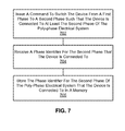
- FIG. 5 is a flowchart illustrating the operations that may be taken for phase identification in a smart meter
- FIG. 6 is another flowchart illustrating the operations that may be taken for phase identification in a smart meter
- FIG. 7 is a flowchart illustrating the operations that can be taken to switch a device from a first phase connection to a second phase connection and to update the phase identifier for the device connection using a computing device such as the one described in reference to FIG. 8 , below;
- FIG. 8 is a block diagram illustrating an exemplary operating environment for performing the disclosed methods.
- the word “comprise” and variations of the word, such as “comprising” and “comprises,” means “including but not limited to,” and is not intended to exclude, for example, other additives, components, integers or steps.
- “Exemplary” means “an example of” and is not intended to convey an indication of a preferred or ideal embodiment. “Such as” is not used in a restrictive sense, but for explanatory purposes.
- FIG. 1A is a single-line block diagram of a section of an exemplary utility distribution system such as, for example, an electric distribution system.
- a utility service is delivered by a utility provider 100 to various loads L 1 -L n 102 through a distribution system 104 .
- the utility service provided can be electric power.
- the distribution system 104 can be comprised of single-phase and/or poly-phase components and be of varying voltage levels.
- the meters 106 can be single-phase or poly-phase electric meters, as known to one of ordinary skill in the art, depending upon the load 102 .
- the load can be single-phase and therefore the meter 106 can be single phase.
- Single-phase loads can be connected to different phases (e.g., phase A, phase B or phase C) of the distribution system 104 .
- the load 102 can be a poly-phase load such as a three-phase load and the meter 106 can be a three-phase meter that meters the three phases serving the load 102 .
- the electric meter 106 is a smart meter as described herein and as known to one of ordinary skill in the art.
- the specification will refer to the meter 106 as a “meter,” “electric meter,” and/or “smart meter,” where the terms can be used interchangeably.
- a smart meter is the GE 1210+c meter as available from General Electric Company (“GE”) (Schenectady, N.Y.).
- GE General Electric Company
- Another non-limiting example of a smart meter is the GE SM3000 meter as also available from GE. While consumption or demand information is used by the utility provider 100 primarily for billing the consumer, it also can be used for other purposes including planning and profiling the utility distribution system.
- utility providers 100 desire to electronically communicate with the meters 106 for numerous purposes including scheduling disconnection or connection of utility services to the loads 102 , automatic meter reading (AMR), load shedding and load control, automatic distribution and smart-grid applications, outage reporting, providing additional services such as Internet, video, and audio, etc.
- AMR automatic meter reading
- the meters 106 must be configured to communicate with one or more computing devices 108 through a communications network 110 , which can be wired, wireless or a combination of wired and wireless, as known to one of ordinary skill in the art.
- the network 110 is an advanced metering infrastructure (AMI) network.
- AMI advanced metering infrastructure
- the system assists a change in energy usage from their normal consumption patterns, either in response to changes in price or as incentives designed to encourage lower energy usage use at times of peak-demand periods or higher wholesale prices or during periods of low operational systems reliability.
- the network 110 comprises at least a portion of a smart grid network.
- the network 110 utilizes one or more of one or more of a WPAN (e.g., ZigBee, Bluetooth), LAN/WLAN (e.g., 802.11n, microwave, laser, etc.), WMAN (e.g., WiMAX, etc.), WAN/WWAN (e.g., UMTS, GPRS, EDGE, CDMA, GSM, CDPD, Mobitex, HSDPA, HSUPA, 3G, etc.), RS232, USB, Firewire, Ethernet, wireless USB, cellular, OpenHAN, power line carrier (PLC), broadband over power lines (BPL), and the like.
- WPAN e.g., ZigBee, Bluetooth
- LAN/WLAN e.g., 802.11n, microwave, laser, etc.
- WMAN e.g., WiMAX, etc.
- WAN/WWAN e.g., UMTS, GPRS, EDGE, CDMA, GSM, CDPD, Mobitex, H
- an electrical distribution system 104 may be a poly-phase system such as a three-phase, four-wire network, which supplies power-using feeders.
- Each of the feeder lines then branches into multiple circuits to power a plurality of local pole-mounted or pad-mounted transformers, which step the voltage down to final voltages of, for example, 120 or 240 volts per phase for delivery and metering at commercial and residential customer locations.
- residential customers can be connected to any one phase of the three-phase system using a single-phase meter and commercial customers can be connected to all the three phases using three-phase meter with a load control relay (“LCR”) connected on any one of the phases.
- LCR load control relay
- FIG. 1B is an exemplary illustration of a three-phase, four-wire (phases A, B, C and neutral, N) distribution system 104 according to one embodiment of the present invention.
- distribution system 104 is comprised of three phase conductors (phases A, B and C) and a neutral wire. In one aspect, each of three phases and the neutral are provided to each meter 106 .
- the voltage provided at the meters 106 is stepped down by a transformer 114 to a level that can be used by the load 102 (e.g. 120/240, 277/480, and the like).
- the transformer 114 can be two or three single-phase transformers, or a single three-phase transformer.
- the load 102 can be single phase
- the meter 106 can be configured to switch between phases A, B and C to serve the load 102 , or to disconnect the load 102 from electric service. In one aspect, this switching can be manually performed. In another aspect, this switching can be performed automatically and remotely.
- the load 102 can be three-phase and can be metered by a three-phase meter 106 .
- the three-phase meter can comprise a load control relay (LCR) 112 .
- the three-phase meter 106 can be configured to switch between phases A, B and C to serve the LCR 112 , or to disconnect the LCR 112 from electric service. In one aspect, this switching can be manually performed. In another aspect, this switching can be performed automatically and remotely. For balancing the load on each phase of the distribution system 104 and performing other utility functions and analysis, it is desired to know the phase that a load 102 is connected or the phase that a LCR 112 is connected.
- a field for phase identification is maintained in a memory of a smart meter.
- the phase identifier can be read or written (depending on security) by a utility using advanced communication techniques such as AMI, Optical, RF, WiMax, LAN/WAN, GSM, etc., and meter software (e.g., GE Meter MateTM software).
- advanced communication techniques such as AMI, Optical, RF, WiMax, LAN/WAN, GSM, etc.
- meter software e.g., GE Meter MateTM software.
- this field can represent the phase to which the main relay is connected and in the case of poly-phase meter (e.g., three-phase), this field can represent the phase to which an LCR is connected.
- the phase identification field can be configured to update automatically.
- phase identification field can be provided over the network to the meter if an entire feeder has been switched using, for example, automated distribution switches as part of a smart-grid implementation.
- phase identification field can be stored manually whenever phase configuration as stated above is changed for a particular meter.
- phase identifier field upon receiving a command to switch phases (for example, from phase A to phase B), the phase to which meter is currently connected is read (phase A) and a relay will be switched to phase B and the phase identifier field will be updated from phase A to phase B.
- phase A the phase to which meter is currently connected
- a relay will be switched to phase B and the phase identifier field will be updated from phase A to phase B.
- software for example, GE Meter MateTM software
- Phase change events can be logged in an event log kept at either or both the meter and the computing device 108 for future reference.
- FIG. 2 illustrates an overview block diagram of a non-limiting embodiment of a meter 106 that can be used to practice embodiments of the present invention.
- the utility service is poly-phase electric power.
- the electric service is three-phase, four-wire electric power generally comprised of three phase conductors 202 each carrying electric voltage and current that is generally displaced from one another by 120 degrees (e.g., phases A, B and C) and a separate neutral wire 214 .
- the embodiments of the invention can be used with single- and poly-phase electrical systems such as two-phase, three-phase, four-phase, etc.
- a switch 204 Further comprising the embodiment of a meter 106 shown in FIG. 2 is a switch 204 .
- the switch 204 can be a single switch or any combination of single or multi-pole switches that provide a means to selectively switch the power feed 104 that provides electrical service from among the plurality of phase conductors 202 (e.g., phases A, B or C), or to disconnect the load 102 from electrical service.
- the load 102 can be provided with single-phase electrical service from among any of a plurality of phases.
- a meter 106 can be configured to switch among two, three, four, five, etc. phases, and is not limited to just a three-phase configuration to provide single-phase service to the load 102 .
- the switch 204 can be controlled by a control mechanism 212 that actuates the switch 204 (i.e., causes it to switch from one phase to another or to disconnect the load).
- the control mechanism 212 receives a control signal from the meter's electronics 206 .
- the control mechanism 212 can provide a feedback signal to the meter's electronics 206 that indicates the position of the switch 204 .
- the control mechanism 212 can inform the meter's electronics whether the load 102 is being provided single-phase electric service from phase A, phase B, phase C, etc., or whether the load 102 is disconnected from electric service.
- Analog voltage and current inputs are also provided to meter electronics 206 .
- the analog signals are derived from the electrical power feed 104 serving the load 102 and the one being metered by the meter 106 .
- the analog signals are derived from a separate electrical source.
- the analog voltage signal can be provided by one or more potential transformers (PT) 208 , if needed, though other means such as a voltage divider, capacitive coupling, or the like can be used. If the voltage level of the source is sufficiently low (e.g., 0.25 volts AC, or lower), then a PT 208 or other means of stepping down or transforming the voltage can be omitted.
- PT potential transformers
- the analog current signal can be provided by one or more current transformers (CT) 210 .
- CT current transformers
- the one or more CTs 210 can have a turns ratio of 1:2500.
- one or more resistors (not shown) can be used to convert the current signal from the CT 210 into a voltage signal.
- phase identifier in the memory is then updated to reflect that the load 102 and meter 106 are now connected to phase B.
- the phase identifier can be stored in the meter 106 manually by a user that has authorization to write to the memory using, for example, infrared, near-field communications such as BlueTooth, Wi-Fi, RF, RFID, and the like, or by connecting a device such as a computer to the meter 106 using a bus connection.
- the phase identifier can be communicated to the memory in the meter's electronics 206 via a network 110 that is operably connected with the meter's electronics 206 .
- the network 110 is an advanced metering infrastructure (AMI) network.
- AMI advanced metering infrastructure
- phase A becomes phase B or some other similar switching
- a signal can be sent to the meter's electronics 206 over the network to update the phase identifier such that indicates the meter 206 and the load 102 are connected to phase B.
- the phase identifier Once the phase identifier is stored in the memory, it can be transmitted over the network 110 to, for example, the computing device 108 or it can be read from the memory by a user with proper authorization and equipment.
- the electronics 206 comprise at least a memory, and one or more processors and provide an interface for receiving a signal from the network 110 and causing the switch 204 to actuate via the control mechanism 212 .
- the memory of the meter electronics 206 can be used to store a phase identifier as described above.
- the meter electronics 206 can comprise a transmitter that can be used to transmit at least the phase identifier over the network 110 to a separate computing device 108 .
- the meter's electronics 206 can comprise one or more metering micro-controllers including a Teridian 6533 controller or a Teridian 6521 controller as are available from Maxim Integrated Products, Inc. (Sunnyvale, Calif.), among others.
- the one or more processors can perform metering functions such as determining the number of kilowatt-hours (KWH) of electricity consumed by the load 102 .
- KWH kilowatt-hours
- the one or more processors of the meter electronics 206 can be configured to store a first phase identifier for the first phase of the poly-phase electrical system that the load 102 is connected to in the memory. Then, when requested, the processor can retrieve the first phase identifier for the first phase of the poly-phase electrical system that the device is connected to from the memory and transmit at least the first phase identifier to the computing device 108 over the network 110 operably connected with the smart meter 106 using the network interface.
- the network 110 is an advanced metering infrastructure (AMI) network.
- AMI advanced metering infrastructure
- the switch 204 can be used to switch the load 102 such that the load is connected to at least a second phase of the poly-phase electrical system such that the metering components meter at least the second phase of the poly-phase electrical system that the load 102 is connected to for electrical consumption information using the smart meter 102 .
- the one or more processors are further configured to store a second phase identifier for the second phase of the poly-phase electrical system that the load 102 is connected to in the memory associated with the smart meter 106 .
- the one or more processors are also configured to retrieve the second phase identifier for the second phase of the poly-phase electrical system that the load 102 is connected to from the memory and transmit at least the second phase identifier to the computing device 108 over the network 110 operably connected with the smart meter 106 using the network interface.
- the switch 204 is an automatic switch controlled by the processor and switching the load 102 such that the load 102 is connected to at least the second phase of the poly-phase electrical system comprises automatically switching the load 102 from the first phase to the second phase of the poly-phase electrical system using the switch 204 .
- the one or more processors are operably connected with the switch 204 such that storing the second phase identifier for the second phase of the poly-phase electrical system that the load 102 is connected to in the memory associated with the smart meter 106 comprises automatically storing the second phase identifier in the memory when the device is switched from the first phase to the second phase of the poly-phase electrical system.
- FIG. 3 illustrates an embodiment of a meter 106 used to meter a poly-phase electrical service 104 serving a load 102 .
- the poly-phase electrical service 104 is a three-phase service comprised of phase conductors 202 for phase A, phase B and phase C, and a neutral wire 214 .
- switch 204 is used to provide electrical power to a load control relay (LCR) 302 .
- LCR load control relay
- the LCR can be used to turn on or off select loads using the meter 106 .
- the LCR can be used to turn on or off power to a hot water heater, swimming pool pump or heater, air conditioning equipment, etc.
- the LCR 302 can have a 40-amp rating. In another aspect, the LCR 302 can have a two-amp rating. In one aspect, the LCR 302 can receive control signals from the meter's electronics 206 . In another aspect, the LCR 302 can receive control signals external from the meter 106 . For example, the LCR 302 can receive a wireless signal causing the LCR 302 to open or close. As shown in FIG. 3 , the switch 204 can be used to connect the LCR to one of phases A, B, or C, or to disconnect it altogether. Though shown as a three-pole, single-throw switch, the switch 204 can be a single switch or a plurality of switches having any number of poles and/or throws.
- the control mechanism 212 of FIG. 3 is used to actuate the switch 204 (i.e., causes it to switch from one phase to another or to disconnect the LCR 302 ).
- the control mechanism 212 receives a control signal from the meter's electronics 206 .
- the control mechanism 212 can provide a feedback signal to the meter's electronics 206 that indicates the position of the switch 204 .
- the control mechanism 212 can inform the meter's electronics whether the LCR 302 is being provided single-phase electric service from phase A, phase B, phase C, etc., or whether the LCR 302 is disconnected from electric service.
- the meter electronics 206 can comprise a memory (not shown in FIG. 3 ).
- the memory can be used to store a phase identifier that indicates the phase of the poly-phase electrical system that the LCR 302 is connected. For example, if the switch 204 is configured such that the phase serving the LCR 302 is phase A, then the phase identifier stored in the memory indicates phase A. Similarly, if the switch 204 switches from phase A to phase B, then the phase identifier stored in the memory indicates phase B.
- the phase identifier is stored automatically when the LCR 302 is switched from one phase to another (e.g., from phase A to phase B).
- the control mechanism 212 can provide a signal that indicates the phase that the LCR 302 is connected to.
- a signal can be sent to the meter 106 over a network 110 .
- the network 110 is an advanced metering infrastructure (AMI) network.
- the signal can be a command to switch phases to which the LCR 302 is connected from a first phase (e.g., phase A) to a second phase (e.g., phase B), or to disconnect the LCR 302 .
- the command is received by a processor (not shown in FIG. 3 ) in the meter's electronics 206 , which causes the control mechanism 212 to switch the connection from phase A to phase B.
- the phase identifier in the memory is then updated to reflect that the LCR 302 is now connected to phase B.
- the phase identifier can be stored in the meter 106 manually by a user that has authorization to write to the memory using, for example, infrared, near-field communications such as BlueTooth, Wi-Fi, RF, RFID, and the like, or by connecting a device such as a computer to the meter 106 using a bus connection.
- the phase identifier can be communicated to the memory in the meter's electronics 206 via a network 110 that is operably connected with the meter's electronics 206 .
- phase A becomes phase B or some other similar switching
- a signal can be sent to the meter's electronics 206 over the network 110 to update the phase identifier such that it indicates the LCR 302 is connected to phase B.
- the phase identifier Once the phase identifier is stored in the memory, it can be transmitted over the network 110 to, for example, the computing device 108 or it can be read from the memory by a user with proper authorization and equipment.
- the electronics 206 comprise at least a memory, and one or more processors and provide an interface for receiving a signal from the network 110 and causing the switch 204 to actuate via the control mechanism 212 .
- the memory of the meter electronics 206 can be used to store a phase identifier as described above.
- the meter electronics 206 can comprise a transmitter that can be used to transmit at least the phase identifier over the network 110 to a separate computing device 108 .
- the network 110 is an advanced metering infrastructure (AMI) network.
- the meter's electronics 206 can comprise one or more metering micro-controllers including a Teridian 6533 controller or a Teridian 6521 controller as are available from Maxim Integrated Products, Inc.
- the one or more processors can perform metering functions such as determining the number of kilowatt-hours (KWH) of electricity consumed by the load 102 .
- Analog voltage and current inputs are also provided to meter electronics 206 .
- the analog signals are derived from the electrical power feed 104 serving the load 102 and the one being metered by the meter 106 .
- the analog signals are derived from a separate electrical source.
- the analog voltage signal can be provided by one or more potential transformers (PT) 208 , if needed, though other means such as a voltage divider, capacitive coupling, or the like can be used.
- PT potential transformers
- the analog current signal can be provided by one or more current transformers (CT) 210 .
- CT current transformers
- the one or more CTs 210 can have a turns ratio of 1:2500.
- one or more resistors (not shown) can be used to convert the current signal from the CT 210 into a voltage signal.
- the one or more processors of the meter electronics 206 can be configured to store a first phase identifier for the first phase of the poly-phase electrical system that the LCR 302 is connected to in the memory. Then, when requested, the processor can retrieve the first phase identifier for the first phase of the poly-phase electrical system that the LCR 302 is connected to from the memory and transmit at least the first phase identifier to the computing device 108 over the network 110 operably connected with the smart meter 106 using the network interface.
- the switch 204 can be used to switch the LCR 302 such that the LCR 302 is connected to at least a second phase of the poly-phase electrical system.
- the one or more processors are further configured to store a second phase identifier for the second phase of the poly-phase electrical system that the LCR 302 is connected to in the memory associated with the smart meter 106 .
- the one or more processors are also configured to retrieve the second phase identifier for the second phase of the poly-phase electrical system that the LCR 302 is connected to from the memory and transmit at least the second phase identifier to the computing device 108 over the network 110 operably connected with the smart meter 106 using the network interface.
- the switch 204 is an automatic switch controlled by the processor and switching the LCR 302 such that the LCR 302 is connected to at least the second phase of the poly-phase electrical system comprises automatically switching the LCR 302 from the first phase to the second phase of the poly-phase electrical system using the switch 204 .
- the one or more processors are operably connected with the switch 204 such that storing the second phase identifier for the second phase of the poly-phase electrical system that the LCR 302 is connected to in the memory associated with the smart meter 106 comprises automatically storing the second phase identifier in the memory when the device is switched from the first phase to the second phase of the poly-phase electrical system.
- FIG. 4 a block diagram of an entity capable of operating as meter electronics 206 is shown in accordance with one embodiment of the present invention.
- the entity capable of operating as a meter electronics 206 includes various means for performing one or more functions in accordance with embodiments of the present invention, including those more particularly shown and described herein. It should be understood, however, that one or more of the entities may include alternative means for performing one or more like functions, without departing from the spirit and scope of the present invention.
- the entity capable of operating as a meter electronics 206 can generally include means, such as one or more processors 404 for performing or controlling the various functions of the entity. As shown in FIG.
- meter electronics 206 can comprise metering components such as meter inputs and filtering components 402 .
- the meter inputs and filter components 402 can comprise voltage and current inputs, one or more ADCs, filtering components, and the like.
- processors 404 and memory 406 Further comprising this embodiment of meter electronics 206 are one or more processors 404 and memory 406 .
- the one or more processors 404 are in communication with or include memory 406 , such as volatile and/or non-volatile memory that stores content, data or the like.
- the memory 406 may store content transmitted from, and/or received by, the entity.
- the memory 406 may store software applications, instructions or the like for the one or more processors 404 to perform steps associated with operation of the entity in accordance with embodiments of the present invention.
- the one or more processors 404 may be configured to perform the processes discussed in more detail herein for receiving an actuation command for a switch, causing a control associated with the switch to implement the actuation, receiving a phase identifier from the switch, and transmitting the phase identifier to a computing device over a network.
- the one or more processors 404 can be configured to update the phase identifier when a device (e.g., a load or a LCR) is switched from a first phase to a second phase, as described herein.
- a device e.g., a load or a LCR
- the one or more processors 404 can also be connected to at least one interface or other means for displaying, transmitting and/or receiving data, content or the like.
- the interface(s) can include at least one communication interface 408 or other means for transmitting and/or receiving data, content or the like, as well as at least one user interface that can include a display 410 and/or a user input interface 412 .
- the communication interface 408 can be used to transfer a phase identifier stored in the memory 406 to a remote computing device such as the one described below over a network 110 .
- the network 110 is an advanced metering infrastructure (AMI) network.
- AMI advanced metering infrastructure
- the communication interface 608 can comprise a wireless communication interface such as a Wi-Fi transceiver.
- the user input interface 412 can comprise any of a number of devices allowing the entity to receive data from a user, such as a keypad, a touch display, a joystick or other input device.
- a device is connected to at least a first phase of a poly-phase electrical system.
- the device is an electrical load.
- the electrical load is a single-phase electrical load.
- the electrical load is a poly-phase electrical load.
- the poly-phase electrical load is a three-phase electrical load.
- the device is a load control relay (LCR).
- LCR load control relay
- a first phase identifier for the first phase of the poly-phase electrical system that the device is connected to is stored in a memory associated with the smart meter.
- at least the first phase identifier is transmitted over a network operably connected with the smart meter.
- the network 110 is an advanced metering infrastructure (AMI) network.
- AMI advanced metering infrastructure
- the operations for phase identification in a smart meter as shown in FIG. 5 can further include the steps illustrated in FIG. 6 .
- the device can be switched such that the device is connected to at least a second phase of the poly-phase electrical system.
- switching the device such that the device is connected to at least the second phase of the poly-phase electrical system comprises automatically switching the device from the first phase to the second phase of the poly-phase electrical system using the smart meter.
- at least the second phase of the poly-phase electrical system that the device is connected to is metered for electrical consumption information using the smart meter.
- a second phase identifier for the second phase of the poly-phase electrical system that the device is connected to is stored in the memory associated with the smart meter.
- storing the second phase identifier for the second phase of the poly-phase electrical system that the device is connected to in the memory associated with the smart meter comprises automatically storing the second phase identifier when the device is switched from the first phase to the second phase of the poly-phase electrical system.
- the second phase identifier is transmitted over the network operably connected with the smart meter.
- a phase identifier for the second phase that the device is connected to is received by the computing device from the smart meter.
- the phase identifier can be an identifier that identifies the phase that the device is connected to as phase A, phase B, Phase C, or the like.
- the phase identifier is stored in the memory of the computing device.
- a unit such as a smart appliance, a smart meter, a smart grid, a utility computing device, a vendor or manufacturer's computing device, etc., can be software, hardware, or a combination of software and hardware.
- the units can comprise the switching software 806 as illustrated in FIG. 8 and described below.
- the units can comprise a computing device 108 as referenced above and further described below.
- FIG. 8 is a block diagram illustrating an exemplary operating environment for performing the disclosed methods.
- This exemplary operating environment is only an example of an operating environment and is not intended to suggest any limitation as to the scope of use or functionality of operating environment architecture. Neither should the operating environment be interpreted as having any dependency or requirement relating to any one or combination of components illustrated in the exemplary operating environment.
- the present methods and systems can be operational with numerous other general purpose or special purpose computing system environments or configurations.
- Examples of well known computing systems, environments, and/or configurations that can be suitable for use with the systems and methods comprise, but are not limited to, personal computers, server computers, laptop devices, and multiprocessor systems. Additional examples comprise set top boxes, programmable consumer electronics, network PCs, minicomputers, mainframe computers, smart meters, smart-grid components, distributed computing environments that comprise any of the above systems or devices, and the like.
- the processing of the disclosed methods and systems can be performed by software components.
- the disclosed systems and methods can be described in the general context of computer-executable instructions, such as program modules, being executed by one or more computers or other devices.
- program modules comprise computer code, routines, programs, objects, components, data structures, etc. that perform particular tasks or implement particular abstract data types.
- the disclosed methods can also be practiced in grid-based and distributed computing environments where tasks are performed by remote processing devices that are linked through a communications network.
- program modules can be located in both local and remote computer storage media including memory storage devices.
- the systems and methods disclosed herein can be implemented via a general-purpose computing device in the form of a computing device 108 .
- the components of the computing device 108 can comprise, but are not limited to, one or more processors or processing units 803 , a system memory 812 , and a system bus 813 that couples various system components including the processor 803 to the system memory 812 .
- the system can utilize parallel computing.
- the processor 803 is configured to send an actuation signal to a smart meter and receive a phase identifier from the smart meter in accordance with the electrical phase that the device at the smart meter is connected.
- the system bus 813 represents one or more of several possible types of bus structures, including a memory bus or memory controller, a peripheral bus, an accelerated graphics port, and a processor or local bus using any of a variety of bus architectures.
- bus architectures can comprise an Industry Standard Architecture (ISA) bus, a Micro Channel Architecture (MCA) bus, an Enhanced ISA (EISA) bus, a Video Electronics Standards Association (VESA) local bus, an Accelerated Graphics Port (AGP) bus, and a Peripheral Component Interconnects (PCI), a PCI-Express bus, a Personal Computer Memory Card Industry Association (PCMCIA), Universal Serial Bus (USB) and the like.
- ISA Industry Standard Architecture
- MCA Micro Channel Architecture
- EISA Enhanced ISA
- VESA Video Electronics Standards Association
- AGP Accelerated Graphics Port
- PCI Peripheral Component Interconnects
- PCI-Express PCI-Express
- PCMCIA Personal Computer Memory Card Industry Association
- USB Universal Serial Bus
- the bus 813 and all buses specified in this description can also be implemented over a wired or wireless network connection and each of the subsystems, including the processor 803 , a mass storage device 804 , an operating system 805 , switching software 806 , phase identifier data 807 , a network adapter 808 , system memory 812 , an Input/Output Interface 810 , a display adapter 809 , a display device 811 , and a human machine interface 802 , can be contained within one or more remote computing devices or clients 814 a,b,c at physically separate locations, connected through buses of this form, in effect implementing a fully distributed system or distributed architecture.
- the computing device 108 typically comprises a variety of computer readable media. Exemplary readable media can be any available media that is non-transitory and accessible by the computing device 108 and comprises, for example and not meant to be limiting, both volatile and non-volatile media, removable and non-removable media.
- the system memory 812 comprises computer readable media in the form of volatile memory, such as random access memory (RAM), and/or non-volatile memory, such as read only memory (ROM).
- RAM random access memory
- ROM read only memory
- the system memory 812 typically contains data such as phase identifier data 807 and/or program modules such as operating system 805 and switching software 806 that are immediately accessible to and/or are presently operated on by the processing unit 803 .
- the computing device 108 can also comprise other non-transitory, removable/non-removable, volatile/non-volatile computer storage media.
- FIG. 8 illustrates a mass storage device 804 that can provide non-volatile storage of computer code, computer readable instructions, data structures, program modules, and other data for the computing device 108 .
- a mass storage device 804 can be a hard disk, a removable magnetic disk, a removable optical disk, magnetic cassettes or other magnetic storage devices, flash memory cards, CD-ROM, digital versatile disks (DVD) or other optical storage, random access memories (RAM), read only memories (ROM), electrically erasable programmable read-only memory (EEPROM), and the like.
- any number of program modules can be stored on the mass storage device 604 , including by way of example, an operating system 805 and switching software 806 .
- Each of the operating system 805 and switching software 806 (or some combination thereof) can comprise elements of the programming and the switching software 806 .
- Phase identifier data 807 can also be stored on the mass storage device 804 .
- Phase identifier data 807 can be stored in any of one or more databases known in the art. Examples of such databases comprise, DB2® (IBM Corporation, Armonk, N.Y.), Microsoft® Access, Microsoft® SQL Server, (Microsoft Corporation, Bellevue, Wash.), Oracle®, (Oracle Corporation, Redwood Shores, Calif.), mySQL, PostgreSQL, and the like.
- the databases can be centralized or distributed across multiple systems.
- the user can enter commands and information into the computing device 108 via an input device (not shown).
- input devices comprise, but are not limited to, a keyboard, pointing device (e.g., a “mouse”), a microphone, a joystick, a scanner, tactile input devices such as gloves, and other body coverings, and the like
- a human machine interface 802 that is coupled to the system bus 813 , but can be connected by other interface and bus structures, such as a parallel port, game port, an IEEE 1394 Port (also known as a Firewire port), a serial port, or a universal serial bus (USB).
- a display device 811 can also be connected to the system bus 813 via an interface, such as a display adapter 809 . It is contemplated that the computing device 108 can have more than one display adapter 809 and the computing device 108 can have more than one display device 811 .
- a display device can be a monitor, an LCD (Liquid Crystal Display), or a projector.
- other output peripheral devices can comprise components such as speakers (not shown) and a printer (not shown), which can be connected to the computer 801 via Input/Output Interface 810 . Any step and/or result of the methods can be output in any form to an output device. Such output can be any form of visual representation, including, but not limited to, textual, graphical, animation, audio, tactile, and the like.
- the computing device 108 can operate in a networked environment using logical connections to one or more remote computing devices or clients 814 a,b,c .
- a remote computing device 814 can be a personal computer, portable computer, a server, a router, a network computer, a smart meter, a vendor or manufacture's computing device, smart grid components, a peer device or other common network node, and so on.
- Logical connections between the computing device 108 and a remote computing device or client 814 a,b,c can be made via a local area network (LAN) and a general wide area network (WAN).
- LAN local area network
- WAN general wide area network
- Such network connections can be through a network adapter 608 .
- a network adapter 808 can be implemented in both wired and wireless environments. Such networking environments are conventional and commonplace in offices, enterprise-wide computer networks, intranets, and other networks 815 such as the Internet or an AMI network.
- application programs and other executable program components such as the operating system 805 are illustrated herein as discrete blocks, although it is recognized that such programs and components reside at various times in different storage components of the computing device 801 , and are executed by the data processor(s) of the computer.
- An implementation of switching software 806 can be stored on or transmitted across some form of computer readable media. Any of the disclosed methods can be performed by computer readable instructions embodied on computer readable media.
- Computer readable media can be any available media that can be accessed by a computer.
- Computer readable media can comprise “computer storage media” and “communications media.”
- “Computer storage media” comprise volatile and non-volatile, removable and non-removable media implemented in any methods or technology for storage of information such as computer readable instructions, data structures, program modules, or other data.
- Exemplary computer storage media comprises, but is not limited to, RAM, ROM, EEPROM, flash memory or other memory technology, CD-ROM, digital versatile disks (DVD) or other optical storage, magnetic cassettes, magnetic tape, magnetic disk storage or other magnetic storage devices, or any other medium which can be used to store the desired information and which can be accessed by a computer.
- the methods and systems can employ Artificial Intelligence techniques such as machine learning and iterative learning.
- Artificial Intelligence techniques such as machine learning and iterative learning. Examples of such techniques include, but are not limited to, expert systems, case based reasoning, Bayesian networks, behavior based AI, neural networks, fuzzy systems, evolutionary computation (e.g. genetic algorithms), swarm intelligence (e.g. ant algorithms), and hybrid intelligent systems (e.g. Expert inference rules generated through a neural network or production rules from statistical learning).
- embodiments of the present invention may be configured as a system, method, or computer program product. Accordingly, embodiments of the present invention may be comprised of various means including entirely of hardware, entirely of software, or any combination of software and hardware. Furthermore, embodiments of the present invention may take the form of a computer program product on a computer-readable storage medium having computer-readable program instructions (e.g., computer software) embodied in the storage medium. Any suitable non-transitory computer-readable storage medium may be utilized including hard disks, CD-ROMs, optical storage devices, or magnetic storage devices.
- Embodiments of the present invention have been described above with reference to block diagrams and flowchart illustrations of methods, apparatuses (i.e., systems) and computer program products. It will be understood that each block of the block diagrams and flowchart illustrations, and combinations of blocks in the block diagrams and flowchart illustrations, respectively, can be implemented by various means including computer program instructions. These computer program instructions may be loaded onto a general purpose computer, special purpose computer, or other programmable data processing apparatus, such as the one or more processors 803 discussed above with reference to FIG. 8 or the one or more processors 404 of FIG. 4 , to produce a machine, such that the instructions which execute on the computer or other programmable data processing apparatus create a means for implementing the functions specified in the flowchart block or blocks.
- These computer program instructions may also be stored in a computer-readable memory that can direct a computer or other programmable data processing apparatus (e.g., one or more processors 803 of FIG. 8 or the one or more processors 404 of FIG. 4 ), to function in a particular manner, such that the instructions stored in the computer-readable memory produce an article of manufacture including computer-readable instructions for implementing the function specified in the flowchart block or blocks.
- the computer program instructions may also be loaded onto a computer or other programmable data processing apparatus to cause a series of operational steps to be performed on the computer or other programmable apparatus to produce a computer-implemented process such that the instructions that execute on the computer or other programmable apparatus provide steps for implementing the functions specified in the flowchart block or blocks.
- blocks of the block diagrams and flowchart illustrations support combinations of means for performing the specified functions, combinations of steps for performing the specified functions and program instruction means for performing the specified functions. It will also be understood that each block of the block diagrams and flowchart illustrations, and combinations of blocks in the block diagrams and flowchart illustrations, can be implemented by special purpose hardware-based computer systems that perform the specified functions or steps, or combinations of special purpose hardware and computer instructions.
Landscapes
- Engineering & Computer Science (AREA)
- Power Engineering (AREA)
- Physics & Mathematics (AREA)
- General Physics & Mathematics (AREA)
- Remote Monitoring And Control Of Power-Distribution Networks (AREA)
- Arrangements For Transmission Of Measured Signals (AREA)
- Measuring Phase Differences (AREA)
Abstract
Description
- In many instances, utility providers desire to electronically communicate with the utility service meters for numerous purposes including scheduling disconnection or connection of utility services to the metered loads, automatic meter reading (AMR), load shedding and load control, automatic distribution and smart-grid applications, outage reporting, providing additional services such as Internet, video, and audio, etc. In many of these instances, to perform these functions the meters must be configured to communicate with one or more computing devices through a communications network, which can be wired, wireless or a combination of wired and wireless, as known to one of ordinary skill in the art.
- In many instances, such meters are also equipped with an electromechanical switch that can be actuated remotely to perform functions such as disconnection or connection of utility services to the metered loads, load shedding and load control, and the like. However, in many instances the utility also desires to know which phase or phases of a poly-phase electrical system the load is connected, or which phase or phases a load control relay is connected. One challenge faced by the utilities is that the records are incomplete or inaccurate that indicate to a smart meter installer which phase an individual customer is connected. Therefore, in order to accurately identify the current phase of a particular feeder branch, utility company personnel must physically trace a cable run back through various distribution facilities until they reach a point in the distribution network at which the phase is definitively known. This can be a very time-consuming and labor-intensive process, which can often lead to incorrect information. During storms or emergencies this can also lead to safety issues as well. When a utility performs various operations such as load profiling, analyzing power quality, loading of each phase, distribution system planning, and the like, it is important to know on which phase or phases the smart meters are connected so that analysis can be done with respect to each phase.
- Therefore, systems and methods are desired that provide phase identification of a smart meter that overcome challenges present in the art, some of which are described above.
- Described herein are embodiments of methods, devices and systems for phase identification of a smart meter.
- One aspect comprises a method of phase identification for a smart meter. One embodiment of the method comprises connecting a device to at least a first phase of a poly-phase electrical system; metering at least the first phase of the poly-phase electrical system that the device is connected to for electrical consumption information using a smart meter; storing a first phase identifier for the first phase of the poly-phase electrical system that the device is connected to in a memory associated with the smart meter; and transmitting at least the first phase identifier over a network operably connected with the smart meter.
- Another aspect comprises a smart meter. One embodiment of the smart meter is comprised of one or more switches, metering components, a memory, at least one network interface, and a processor. The one or more switches can be used to connect a device to at least a first phase of a poly-phase electrical system. The metering components can be used to meter at least the first phase of the poly-phase electrical system that the device is connected to for electrical consumption information. The processor is operably connected with the one or more switches, the metering components, the memory and the at least one network interface. The processor is configured to: store a first phase identifier for the first phase of the poly-phase electrical system that the device is connected to in the memory; and retrieve the first phase identifier for the first phase of the poly-phase electrical system that the device is connected to from the memory and transmit at least the first phase identifier over a network operably connected with the smart meter using the network interface.
- In yet another aspect, a system is described. One embodiment of the system is comprised of a computing device, a network operably connected to the computing device, and a smart meter operably connected with the network. In one aspect, the smart meter is comprised of one or more switches, metering components, a memory, at least one network interface, and a processor. The one or more switches can be used to connect a device to at least a first phase of a poly-phase electrical system. The metering components can be used to meter at least the first phase of the poly-phase electrical system that the device is connected to for electrical consumption information. The processor is operably connected with the one or more switches, the metering components, the memory and the at least one network interface. The processor is configured to: store a first phase identifier for the first phase of the poly-phase electrical system that the device is connected to in the memory; and retrieve the first phase identifier for the first phase of the poly-phase electrical system that the device is connected to from the memory and transmit at least the first phase identifier over a network operably connected with the smart meter using the network interface.
- Additional advantages will be set forth in part in the description which follows or may be learned by practice. The advantages will be realized and attained by means of the elements and combinations particularly pointed out in the appended claims. It is to be understood that both the foregoing general description and the following detailed description are exemplary and explanatory only and are not restrictive, as claimed.
- The accompanying drawings, which are incorporated in and constitute a part of this specification, illustrate embodiments and together with the description, serve to explain the principles of the methods and systems:
-
FIG. 1A is a single-line block diagram of a section of an exemplary utility distribution system; -
FIG. 1B is an exemplary illustration of a three-phase, four-wire (phases A, B, C and neutral, N)distribution system 104 according to one embodiment of the present invention; -
FIG. 2 illustrates an overview block diagram of a non-limiting embodiment of a meter that can be used to practice embodiments of the present invention; -
FIG. 3 illustrates an embodiment of a meter used to meter a poly-phase electrical service serving a load; -
FIG. 4 illustrates a block diagram of an entity capable of operating as meter electronics in accordance with one embodiment of the present invention; -
FIG. 5 is a flowchart illustrating the operations that may be taken for phase identification in a smart meter; -
FIG. 6 is another flowchart illustrating the operations that may be taken for phase identification in a smart meter; -
FIG. 7 is a flowchart illustrating the operations that can be taken to switch a device from a first phase connection to a second phase connection and to update the phase identifier for the device connection using a computing device such as the one described in reference toFIG. 8 , below; and -
FIG. 8 is a block diagram illustrating an exemplary operating environment for performing the disclosed methods. - Before the present methods and systems are disclosed and described, it is to be understood that the methods and systems are not limited to specific synthetic methods, specific components, or to particular compositions. It is also to be understood that the terminology used herein is for the purpose of describing particular embodiments only and is not intended to be limiting.
- As used in the specification and the appended claims, the singular forms “a,” “an” and “the” include plural referents unless the context clearly dictates otherwise. Ranges may be expressed herein as from “about” one particular value, and/or to “about” another particular value. When such a range is expressed, another embodiment includes from the one particular value and/or to the other particular value. Similarly, when values are expressed as approximations, by use of the antecedent “about,” it will be understood that the particular value forms another embodiment. It will be further understood that the endpoints of each of the ranges are significant both in relation to the other endpoint, and independently of the other endpoint.
- “Optional” or “optionally” means that the subsequently described event or circumstance may or may not occur, and that the description includes instances where said event or circumstance occurs and instances where it does not.
- Throughout the description and claims of this specification, the word “comprise” and variations of the word, such as “comprising” and “comprises,” means “including but not limited to,” and is not intended to exclude, for example, other additives, components, integers or steps. “Exemplary” means “an example of” and is not intended to convey an indication of a preferred or ideal embodiment. “Such as” is not used in a restrictive sense, but for explanatory purposes.
- Disclosed are components that can be used to perform the disclosed methods and systems. These and other components are disclosed herein, and it is understood that when combinations, subsets, interactions, groups, etc. of these components are disclosed that while specific reference of each various individual and collective combinations and permutation of these may not be explicitly disclosed, each is specifically contemplated and described herein, for all methods and systems. This applies to all aspects of this application including, but not limited to, steps in disclosed methods. Thus, if there are a variety of additional steps that can be performed it is understood that each of these additional steps can be performed with any specific embodiment or combination of embodiments of the disclosed methods.
- The present methods and systems may be understood more readily by reference to the following detailed description of preferred embodiments and the Examples included therein and to the Figures and their previous and following description.
- Referring to
FIG. 1A , an illustration of one type of system that would benefit from embodiments of the present invention is provided.FIG. 1A is a single-line block diagram of a section of an exemplary utility distribution system such as, for example, an electric distribution system. As shown inFIG. 1A , a utility service is delivered by autility provider 100 to various loads L1-L n 102 through adistribution system 104. In one aspect, the utility service provided can be electric power. Though shown inFIG. 1A as a single-line diagram, it is to be appreciated that thedistribution system 104 can be comprised of single-phase and/or poly-phase components and be of varying voltage levels. Consumption and demand by theloads 102 can be measured at the load locations by meters M1-M n 106. If an electric meter, themeters 106 can be single-phase or poly-phase electric meters, as known to one of ordinary skill in the art, depending upon theload 102. For example, the load can be single-phase and therefore themeter 106 can be single phase. Single-phase loads can be connected to different phases (e.g., phase A, phase B or phase C) of thedistribution system 104. Similarly, for example, theload 102 can be a poly-phase load such as a three-phase load and themeter 106 can be a three-phase meter that meters the three phases serving theload 102. - In one aspect, the
electric meter 106 is a smart meter as described herein and as known to one of ordinary skill in the art. Hereinafter, the specification will refer to themeter 106 as a “meter,” “electric meter,” and/or “smart meter,” where the terms can be used interchangeably. One non-limiting example of a smart meter is the GE 1210+c meter as available from General Electric Company (“GE”) (Schenectady, N.Y.). Another non-limiting example of a smart meter is the GE SM3000 meter as also available from GE. While consumption or demand information is used by theutility provider 100 primarily for billing the consumer, it also can be used for other purposes including planning and profiling the utility distribution system. In some instances,utility providers 100 desire to electronically communicate with themeters 106 for numerous purposes including scheduling disconnection or connection of utility services to theloads 102, automatic meter reading (AMR), load shedding and load control, automatic distribution and smart-grid applications, outage reporting, providing additional services such as Internet, video, and audio, etc. In many of these instances, themeters 106 must be configured to communicate with one ormore computing devices 108 through acommunications network 110, which can be wired, wireless or a combination of wired and wireless, as known to one of ordinary skill in the art. In one aspect, thenetwork 110 is an advanced metering infrastructure (AMI) network. AMI refers to systems that measure, collect and analyze energy usage, and interact with advanced devices such as electricity meters, gas meters, water meters, and the like through various communication media either on request (on-demand) or on pre-defined schedules. This infrastructure includes hardware, software, communications, consumer energy displays and controllers, customer associated systems, meter data management (MDM) software, supplier and network distribution business systems, and the like. Thenetwork 110 between the measurement devices (e.g., meters 106) and business systems allows collection and distribution of information to customers, suppliers, utility companies and service providers. This enables these businesses to either participate in, or provide, demand response solutions, products and services. By providing information to customers, the system assists a change in energy usage from their normal consumption patterns, either in response to changes in price or as incentives designed to encourage lower energy usage use at times of peak-demand periods or higher wholesale prices or during periods of low operational systems reliability. In one aspect, thenetwork 110 comprises at least a portion of a smart grid network. In one aspect, thenetwork 110 utilizes one or more of one or more of a WPAN (e.g., ZigBee, Bluetooth), LAN/WLAN (e.g., 802.11n, microwave, laser, etc.), WMAN (e.g., WiMAX, etc.), WAN/WWAN (e.g., UMTS, GPRS, EDGE, CDMA, GSM, CDPD, Mobitex, HSDPA, HSUPA, 3G, etc.), RS232, USB, Firewire, Ethernet, wireless USB, cellular, OpenHAN, power line carrier (PLC), broadband over power lines (BPL), and the like.Such meters 106 can be equipped with one or more switches that can be used to remotely connect or disconnect the service or product delivered. - For example, in some instances an
electrical distribution system 104 may be a poly-phase system such as a three-phase, four-wire network, which supplies power-using feeders. Each of the feeder lines then branches into multiple circuits to power a plurality of local pole-mounted or pad-mounted transformers, which step the voltage down to final voltages of, for example, 120 or 240 volts per phase for delivery and metering at commercial and residential customer locations. Generally, residential customers can be connected to any one phase of the three-phase system using a single-phase meter and commercial customers can be connected to all the three phases using three-phase meter with a load control relay (“LCR”) connected on any one of the phases. When a utility performs various operations such as load profiling, analyzing power quality, loading of each phase, etc., it is desired to know on which phase smart meter is connected so that the analysis can be performed with respect to each phase. Such a system as described above is illustrated inFIG. 1B .FIG. 1B is an exemplary illustration of a three-phase, four-wire (phases A, B, C and neutral, N)distribution system 104 according to one embodiment of the present invention. As shown inFIG. 4B ,distribution system 104 is comprised of three phase conductors (phases A, B and C) and a neutral wire. In one aspect, each of three phases and the neutral are provided to eachmeter 106. In one aspect, the voltage provided at themeters 106 is stepped down by atransformer 114 to a level that can be used by the load 102 (e.g. 120/240, 277/480, and the like). Thetransformer 114 can be two or three single-phase transformers, or a single three-phase transformer. In one aspect, theload 102 can be single phase, and themeter 106 can be configured to switch between phases A, B and C to serve theload 102, or to disconnect theload 102 from electric service. In one aspect, this switching can be manually performed. In another aspect, this switching can be performed automatically and remotely. In another aspect, theload 102 can be three-phase and can be metered by a three-phase meter 106. In one aspect, the three-phase meter can comprise a load control relay (LCR) 112. In one aspect, the three-phase meter 106 can be configured to switch between phases A, B and C to serve theLCR 112, or to disconnect theLCR 112 from electric service. In one aspect, this switching can be manually performed. In another aspect, this switching can be performed automatically and remotely. For balancing the load on each phase of thedistribution system 104 and performing other utility functions and analysis, it is desired to know the phase that aload 102 is connected or the phase that aLCR 112 is connected. - Methods, systems and devices to determine the phase to which meter is connected in case of a single-phase meter and the phase to which a LCR is connected in case of poly-phase meter are desired. Therefore, it is desired that the
meters 106 of a system such as that shown inFIGS. 1A and 1B are configured to have capabilities beyond that of measurement of utility service consumption. Described herein are embodiments of methods, devices and systems for phase identification in a smart meter. In one aspect, a field for phase identification is maintained in a memory of a smart meter. The phase identifier can be read or written (depending on security) by a utility using advanced communication techniques such as AMI, Optical, RF, WiMax, LAN/WAN, GSM, etc., and meter software (e.g., GE Meter Mate™ software). In case of a single-phase meter, this field can represent the phase to which the main relay is connected and in the case of poly-phase meter (e.g., three-phase), this field can represent the phase to which an LCR is connected. In one aspect, the phase identification field can be configured to update automatically. For example, if a meter is configured such that it can switch the phase that serves the load (and that is being metered), then such a meter can be configured to automatically populate the phase identifier field with the phase to which the load is connected. Such a meter that can switch phases is described in U.S. patent application Ser. No. 12/987,301 by Pamulaparthy, filed Jan. 10, 2011, which is fully incorporated herein by reference and made a part hereof. In another aspect, the phase identification field can be provided over the network to the meter if an entire feeder has been switched using, for example, automated distribution switches as part of a smart-grid implementation. In another aspect, the phase identification field can be stored manually whenever phase configuration as stated above is changed for a particular meter. For example, in automatic population of the phase identifier field, upon receiving a command to switch phases (for example, from phase A to phase B), the phase to which meter is currently connected is read (phase A) and a relay will be switched to phase B and the phase identifier field will be updated from phase A to phase B. In case of manual, for example, if a utility person changes the connection of meter or LCR from one phase to other, the person can write the field (assuming the person has security access) using software (for example, GE Meter Mate™ software) and any of the communication media such as AMI, Optical, RF, WiMax, LAN/WAN, GSM, etc. Phase change events can be logged in an event log kept at either or both the meter and thecomputing device 108 for future reference. -
FIG. 2 illustrates an overview block diagram of a non-limiting embodiment of ameter 106 that can be used to practice embodiments of the present invention. In this exemplary embodiment, the utility service is poly-phase electric power. Particularly, inFIG. 2 the electric service is three-phase, four-wire electric power generally comprised of threephase conductors 202 each carrying electric voltage and current that is generally displaced from one another by 120 degrees (e.g., phases A, B and C) and a separateneutral wire 214. It is to be appreciated, however, that the embodiments of the invention can be used with single- and poly-phase electrical systems such as two-phase, three-phase, four-phase, etc. Further comprising the embodiment of ameter 106 shown inFIG. 2 is aswitch 204. Theswitch 204, though shown as a three pole, single-throw switch, can be a single switch or any combination of single or multi-pole switches that provide a means to selectively switch thepower feed 104 that provides electrical service from among the plurality of phase conductors 202 (e.g., phases A, B or C), or to disconnect theload 102 from electrical service. In this manner, theload 102 can be provided with single-phase electrical service from among any of a plurality of phases. It is also to be appreciated that such ameter 106 can be configured to switch among two, three, four, five, etc. phases, and is not limited to just a three-phase configuration to provide single-phase service to theload 102. In one aspect, theswitch 204 can be controlled by acontrol mechanism 212 that actuates the switch 204 (i.e., causes it to switch from one phase to another or to disconnect the load). Thecontrol mechanism 212 receives a control signal from the meter'selectronics 206. Furthermore, in one aspect, thecontrol mechanism 212 can provide a feedback signal to the meter'selectronics 206 that indicates the position of theswitch 204. In other words, thecontrol mechanism 212 can inform the meter's electronics whether theload 102 is being provided single-phase electric service from phase A, phase B, phase C, etc., or whether theload 102 is disconnected from electric service. - Analog voltage and current inputs are also provided to
meter electronics 206. In one aspect, the analog signals are derived from theelectrical power feed 104 serving theload 102 and the one being metered by themeter 106. In another aspect, the analog signals are derived from a separate electrical source. In one aspect, the analog voltage signal can be provided by one or more potential transformers (PT) 208, if needed, though other means such as a voltage divider, capacitive coupling, or the like can be used. If the voltage level of the source is sufficiently low (e.g., 0.25 volts AC, or lower), then aPT 208 or other means of stepping down or transforming the voltage can be omitted. Similarly, in one aspect, the analog current signal can be provided by one or more current transformers (CT) 210. In one aspect, the one ormore CTs 210 can have a turns ratio of 1:2500. In one aspect, one or more resistors (not shown) can be used to convert the current signal from theCT 210 into a voltage signal. - In one aspect, the
meter electronics 206 can comprise a memory (not shown inFIG. 2 ). The memory can be used to store a phase identifier that indicates the phase of the poly-phase electrical system that the load 102 (and meter 106) are connected. For example, if theswitch 204 is configured such that theelectrical power feed 104 serving theload 102 and the one being metered by themeter 106 is phase A, then the phase identifier stored in the memory indicates phase A. Similarly, if theswitch 204 switches from phase A to phase B, then the phase identifier stored in the memory is updated to indicate phase B. In one aspect, the phase identifier is stored automatically when thepower feed 104 is switched from one phase to another (e.g., from phase A to phase B). For example, thecontrol mechanism 212 can provide a signal that indicates the phase that theload 102 is connected to. In one non-limiting example, a signal can be sent to themeter 106 over anetwork 110. In one aspect, thenetwork 110 is an advanced metering infrastructure (AMI) network. The signal can be a command to switch phases to which the load is connected from a first phase (e.g., phase A) to a second phase (e.g., phase B), or to disconnect theload 102. The command is received by a processor (not shown inFIG. 2 ) in the meter'selectronics 206, which causes thecontrol mechanism 212 to switch the connection from phase A to phase B. The phase identifier in the memory is then updated to reflect that theload 102 andmeter 106 are now connected to phase B. In another aspect, the phase identifier can be stored in themeter 106 manually by a user that has authorization to write to the memory using, for example, infrared, near-field communications such as BlueTooth, Wi-Fi, RF, RFID, and the like, or by connecting a device such as a computer to themeter 106 using a bus connection. In another aspect, the phase identifier can be communicated to the memory in the meter'selectronics 206 via anetwork 110 that is operably connected with the meter'selectronics 206. In one aspect, thenetwork 110 is an advanced metering infrastructure (AMI) network. For example, if an entire circuit is switched, either automatically or manually, by a utility such that phase A becomes phase B or some other similar switching, then a signal can be sent to the meter'selectronics 206 over the network to update the phase identifier such that indicates themeter 206 and theload 102 are connected to phase B. Once the phase identifier is stored in the memory, it can be transmitted over thenetwork 110 to, for example, thecomputing device 108 or it can be read from the memory by a user with proper authorization and equipment. - In one aspect, the
electronics 206 comprise at least a memory, and one or more processors and provide an interface for receiving a signal from thenetwork 110 and causing theswitch 204 to actuate via thecontrol mechanism 212. The memory of themeter electronics 206 can be used to store a phase identifier as described above. Themeter electronics 206 can comprise a transmitter that can be used to transmit at least the phase identifier over thenetwork 110 to aseparate computing device 108. In one aspect, the meter'selectronics 206 can comprise one or more metering micro-controllers including a Teridian 6533 controller or a Teridian 6521 controller as are available from Maxim Integrated Products, Inc. (Sunnyvale, Calif.), among others. In one aspect, the one or more processors can perform metering functions such as determining the number of kilowatt-hours (KWH) of electricity consumed by theload 102. - In one aspect, the one or more processors of the
meter electronics 206 can be configured to store a first phase identifier for the first phase of the poly-phase electrical system that theload 102 is connected to in the memory. Then, when requested, the processor can retrieve the first phase identifier for the first phase of the poly-phase electrical system that the device is connected to from the memory and transmit at least the first phase identifier to thecomputing device 108 over thenetwork 110 operably connected with thesmart meter 106 using the network interface. In one aspect, thenetwork 110 is an advanced metering infrastructure (AMI) network. In one aspect, theswitch 204 can be used to switch theload 102 such that the load is connected to at least a second phase of the poly-phase electrical system such that the metering components meter at least the second phase of the poly-phase electrical system that theload 102 is connected to for electrical consumption information using thesmart meter 102. The one or more processors are further configured to store a second phase identifier for the second phase of the poly-phase electrical system that theload 102 is connected to in the memory associated with thesmart meter 106. The one or more processors are also configured to retrieve the second phase identifier for the second phase of the poly-phase electrical system that theload 102 is connected to from the memory and transmit at least the second phase identifier to thecomputing device 108 over thenetwork 110 operably connected with thesmart meter 106 using the network interface. In one aspect, theswitch 204 is an automatic switch controlled by the processor and switching theload 102 such that theload 102 is connected to at least the second phase of the poly-phase electrical system comprises automatically switching theload 102 from the first phase to the second phase of the poly-phase electrical system using theswitch 204. In one aspect, the one or more processors are operably connected with theswitch 204 such that storing the second phase identifier for the second phase of the poly-phase electrical system that theload 102 is connected to in the memory associated with thesmart meter 106 comprises automatically storing the second phase identifier in the memory when the device is switched from the first phase to the second phase of the poly-phase electrical system. -
FIG. 3 illustrates an embodiment of ameter 106 used to meter a poly-phaseelectrical service 104 serving aload 102. In this embodiment, the poly-phaseelectrical service 104 is a three-phase service comprised ofphase conductors 202 for phase A, phase B and phase C, and aneutral wire 214. In other embodiments, there can be more or fewer electrical phases and phase conductors. In the embodiment shown inFIG. 3 ,switch 204 is used to provide electrical power to a load control relay (LCR) 302. The LCR can be used to turn on or off select loads using themeter 106. For example, the LCR can be used to turn on or off power to a hot water heater, swimming pool pump or heater, air conditioning equipment, etc. In one aspect, theLCR 302 can have a 40-amp rating. In another aspect, theLCR 302 can have a two-amp rating. In one aspect, theLCR 302 can receive control signals from the meter'selectronics 206. In another aspect, theLCR 302 can receive control signals external from themeter 106. For example, theLCR 302 can receive a wireless signal causing theLCR 302 to open or close. As shown inFIG. 3 , theswitch 204 can be used to connect the LCR to one of phases A, B, or C, or to disconnect it altogether. Though shown as a three-pole, single-throw switch, theswitch 204 can be a single switch or a plurality of switches having any number of poles and/or throws. Similar as described in reference toFIG. 2 , thecontrol mechanism 212 ofFIG. 3 is used to actuate the switch 204 (i.e., causes it to switch from one phase to another or to disconnect the LCR 302). Thecontrol mechanism 212 receives a control signal from the meter'selectronics 206. Furthermore, in one aspect, thecontrol mechanism 212 can provide a feedback signal to the meter'selectronics 206 that indicates the position of theswitch 204. In other words, thecontrol mechanism 212 can inform the meter's electronics whether theLCR 302 is being provided single-phase electric service from phase A, phase B, phase C, etc., or whether theLCR 302 is disconnected from electric service. - In one aspect, the
meter electronics 206 can comprise a memory (not shown inFIG. 3 ). The memory can be used to store a phase identifier that indicates the phase of the poly-phase electrical system that theLCR 302 is connected. For example, if theswitch 204 is configured such that the phase serving theLCR 302 is phase A, then the phase identifier stored in the memory indicates phase A. Similarly, if theswitch 204 switches from phase A to phase B, then the phase identifier stored in the memory indicates phase B. In one aspect, the phase identifier is stored automatically when theLCR 302 is switched from one phase to another (e.g., from phase A to phase B). For example, thecontrol mechanism 212 can provide a signal that indicates the phase that theLCR 302 is connected to. In one non-limiting example, a signal can be sent to themeter 106 over anetwork 110. In one aspect, thenetwork 110 is an advanced metering infrastructure (AMI) network. The signal can be a command to switch phases to which theLCR 302 is connected from a first phase (e.g., phase A) to a second phase (e.g., phase B), or to disconnect theLCR 302. The command is received by a processor (not shown inFIG. 3 ) in the meter'selectronics 206, which causes thecontrol mechanism 212 to switch the connection from phase A to phase B. The phase identifier in the memory is then updated to reflect that theLCR 302 is now connected to phase B. In another aspect, the phase identifier can be stored in themeter 106 manually by a user that has authorization to write to the memory using, for example, infrared, near-field communications such as BlueTooth, Wi-Fi, RF, RFID, and the like, or by connecting a device such as a computer to themeter 106 using a bus connection. In another aspect, the phase identifier can be communicated to the memory in the meter'selectronics 206 via anetwork 110 that is operably connected with the meter'selectronics 206. For example, if an entire circuit is switched, either automatically or manually, by a utility such that phase A becomes phase B or some other similar switching, then a signal can be sent to the meter'selectronics 206 over thenetwork 110 to update the phase identifier such that it indicates theLCR 302 is connected to phase B. Once the phase identifier is stored in the memory, it can be transmitted over thenetwork 110 to, for example, thecomputing device 108 or it can be read from the memory by a user with proper authorization and equipment. - In one aspect, the
electronics 206 comprise at least a memory, and one or more processors and provide an interface for receiving a signal from thenetwork 110 and causing theswitch 204 to actuate via thecontrol mechanism 212. The memory of themeter electronics 206 can be used to store a phase identifier as described above. Themeter electronics 206 can comprise a transmitter that can be used to transmit at least the phase identifier over thenetwork 110 to aseparate computing device 108. In one aspect, thenetwork 110 is an advanced metering infrastructure (AMI) network. In one aspect, the meter'selectronics 206 can comprise one or more metering micro-controllers including a Teridian 6533 controller or a Teridian 6521 controller as are available from Maxim Integrated Products, Inc. (Sunnyvale, Calif.), among others. In one aspect, the one or more processors can perform metering functions such as determining the number of kilowatt-hours (KWH) of electricity consumed by theload 102. Analog voltage and current inputs are also provided tometer electronics 206. In one aspect, the analog signals are derived from theelectrical power feed 104 serving theload 102 and the one being metered by themeter 106. In another aspect, the analog signals are derived from a separate electrical source. In one aspect, the analog voltage signal can be provided by one or more potential transformers (PT) 208, if needed, though other means such as a voltage divider, capacitive coupling, or the like can be used. If the voltage level of the source is sufficiently low (e.g., 0.25 volts AC, or lower), then aPT 208 or other means of stepping down or transforming the voltage can be omitted. Similarly, in one aspect, the analog current signal can be provided by one or more current transformers (CT) 210. In one aspect, the one ormore CTs 210 can have a turns ratio of 1:2500. In one aspect, one or more resistors (not shown) can be used to convert the current signal from theCT 210 into a voltage signal. - In one aspect, the one or more processors of the
meter electronics 206 can be configured to store a first phase identifier for the first phase of the poly-phase electrical system that theLCR 302 is connected to in the memory. Then, when requested, the processor can retrieve the first phase identifier for the first phase of the poly-phase electrical system that theLCR 302 is connected to from the memory and transmit at least the first phase identifier to thecomputing device 108 over thenetwork 110 operably connected with thesmart meter 106 using the network interface. In one aspect, theswitch 204 can be used to switch theLCR 302 such that theLCR 302 is connected to at least a second phase of the poly-phase electrical system. The one or more processors are further configured to store a second phase identifier for the second phase of the poly-phase electrical system that theLCR 302 is connected to in the memory associated with thesmart meter 106. The one or more processors are also configured to retrieve the second phase identifier for the second phase of the poly-phase electrical system that theLCR 302 is connected to from the memory and transmit at least the second phase identifier to thecomputing device 108 over thenetwork 110 operably connected with thesmart meter 106 using the network interface. In one aspect, theswitch 204 is an automatic switch controlled by the processor and switching theLCR 302 such that theLCR 302 is connected to at least the second phase of the poly-phase electrical system comprises automatically switching theLCR 302 from the first phase to the second phase of the poly-phase electrical system using theswitch 204. In one aspect, the one or more processors are operably connected with theswitch 204 such that storing the second phase identifier for the second phase of the poly-phase electrical system that theLCR 302 is connected to in the memory associated with thesmart meter 106 comprises automatically storing the second phase identifier in the memory when the device is switched from the first phase to the second phase of the poly-phase electrical system. - Referring now to
FIG. 4 , a block diagram of an entity capable of operating asmeter electronics 206 is shown in accordance with one embodiment of the present invention. The entity capable of operating as ameter electronics 206 includes various means for performing one or more functions in accordance with embodiments of the present invention, including those more particularly shown and described herein. It should be understood, however, that one or more of the entities may include alternative means for performing one or more like functions, without departing from the spirit and scope of the present invention. As shown, the entity capable of operating as ameter electronics 206 can generally include means, such as one ormore processors 404 for performing or controlling the various functions of the entity. As shown inFIG. 4 , in one embodiment,meter electronics 206 can comprise metering components such as meter inputs andfiltering components 402. In one aspect, the meter inputs and filtercomponents 402 can comprise voltage and current inputs, one or more ADCs, filtering components, and the like. Further comprising this embodiment ofmeter electronics 206 are one ormore processors 404 andmemory 406. - In one embodiment, the one or
more processors 404 are in communication with or includememory 406, such as volatile and/or non-volatile memory that stores content, data or the like. For example, thememory 406 may store content transmitted from, and/or received by, the entity. Also for example, thememory 406 may store software applications, instructions or the like for the one ormore processors 404 to perform steps associated with operation of the entity in accordance with embodiments of the present invention. In particular, the one ormore processors 404 may be configured to perform the processes discussed in more detail herein for receiving an actuation command for a switch, causing a control associated with the switch to implement the actuation, receiving a phase identifier from the switch, and transmitting the phase identifier to a computing device over a network. For example, according to one embodiment the one ormore processors 404 can be configured to update the phase identifier when a device (e.g., a load or a LCR) is switched from a first phase to a second phase, as described herein. - In addition to the
memory 406, the one ormore processors 404 can also be connected to at least one interface or other means for displaying, transmitting and/or receiving data, content or the like. In this regard, the interface(s) can include at least onecommunication interface 408 or other means for transmitting and/or receiving data, content or the like, as well as at least one user interface that can include adisplay 410 and/or auser input interface 412. In one aspect, thecommunication interface 408 can be used to transfer a phase identifier stored in thememory 406 to a remote computing device such as the one described below over anetwork 110. In one aspect, thenetwork 110 is an advanced metering infrastructure (AMI) network. In one aspect, thecommunication interface 608 can comprise a wireless communication interface such as a Wi-Fi transceiver. Theuser input interface 412, in turn, can comprise any of a number of devices allowing the entity to receive data from a user, such as a keypad, a touch display, a joystick or other input device. - Referring now to
FIG. 5 , the operations are illustrated that may be taken for phase identification in a smart meter. Atstep 502, a device is connected to at least a first phase of a poly-phase electrical system. In one aspect, the device is an electrical load. In one aspect, the electrical load is a single-phase electrical load. In one aspect, the electrical load is a poly-phase electrical load. In one aspect, the poly-phase electrical load is a three-phase electrical load. In one aspect, the device is a load control relay (LCR). At step 504, at least the first phase of the poly-phase electrical system that the device is connected to is metered for electrical consumption information using a smart meter. Atstep 506. a first phase identifier for the first phase of the poly-phase electrical system that the device is connected to is stored in a memory associated with the smart meter. Atstep 508, at least the first phase identifier is transmitted over a network operably connected with the smart meter. In one aspect, thenetwork 110 is an advanced metering infrastructure (AMI) network. - In one aspect, the operations for phase identification in a smart meter as shown in
FIG. 5 can further include the steps illustrated inFIG. 6 . Atstep 602, the device can be switched such that the device is connected to at least a second phase of the poly-phase electrical system. In one aspect, switching the device such that the device is connected to at least the second phase of the poly-phase electrical system comprises automatically switching the device from the first phase to the second phase of the poly-phase electrical system using the smart meter. At step 604, at least the second phase of the poly-phase electrical system that the device is connected to is metered for electrical consumption information using the smart meter. Atstep 606, a second phase identifier for the second phase of the poly-phase electrical system that the device is connected to is stored in the memory associated with the smart meter. In one aspect, storing the second phase identifier for the second phase of the poly-phase electrical system that the device is connected to in the memory associated with the smart meter comprises automatically storing the second phase identifier when the device is switched from the first phase to the second phase of the poly-phase electrical system. Atstep 608, the second phase identifier is transmitted over the network operably connected with the smart meter. -
FIG. 7 illustrates the operations that can be taken to switch a device from a first phase connection to a second phase connection and to update the phase identifier for the device connection using a computing device such as the one described in reference toFIG. 8 , below. Atstep 702, a command is issued by a computing device and transmitted to a smart meter. The command is to switch the phase that a device is connected to from a first phase to a second phase using the smart meter. In one aspect, the device is an electrical load (either single-phase or poly-phase). In another aspect, the device is a load control relay (LCR), either single- or poly-phase. Atstep 704, in response to the switch command, a phase identifier for the second phase that the device is connected to is received by the computing device from the smart meter. For example, the phase identifier can be an identifier that identifies the phase that the device is connected to as phase A, phase B, Phase C, or the like. Atstep 706, the phase identifier is stored in the memory of the computing device. - The above system has been described above as comprised of units. One skilled in the art will appreciate that this is a functional description and that software, hardware, or a combination of software and hardware can perform the respective functions. A unit, such as a smart appliance, a smart meter, a smart grid, a utility computing device, a vendor or manufacturer's computing device, etc., can be software, hardware, or a combination of software and hardware. The units can comprise the
switching software 806 as illustrated inFIG. 8 and described below. In one exemplary aspect, the units can comprise acomputing device 108 as referenced above and further described below. -
FIG. 8 is a block diagram illustrating an exemplary operating environment for performing the disclosed methods. This exemplary operating environment is only an example of an operating environment and is not intended to suggest any limitation as to the scope of use or functionality of operating environment architecture. Neither should the operating environment be interpreted as having any dependency or requirement relating to any one or combination of components illustrated in the exemplary operating environment. - The present methods and systems can be operational with numerous other general purpose or special purpose computing system environments or configurations. Examples of well known computing systems, environments, and/or configurations that can be suitable for use with the systems and methods comprise, but are not limited to, personal computers, server computers, laptop devices, and multiprocessor systems. Additional examples comprise set top boxes, programmable consumer electronics, network PCs, minicomputers, mainframe computers, smart meters, smart-grid components, distributed computing environments that comprise any of the above systems or devices, and the like.
- The processing of the disclosed methods and systems can be performed by software components. The disclosed systems and methods can be described in the general context of computer-executable instructions, such as program modules, being executed by one or more computers or other devices. Generally, program modules comprise computer code, routines, programs, objects, components, data structures, etc. that perform particular tasks or implement particular abstract data types. The disclosed methods can also be practiced in grid-based and distributed computing environments where tasks are performed by remote processing devices that are linked through a communications network. In a distributed computing environment, program modules can be located in both local and remote computer storage media including memory storage devices.
- Further, one skilled in the art will appreciate that the systems and methods disclosed herein can be implemented via a general-purpose computing device in the form of a
computing device 108. The components of thecomputing device 108 can comprise, but are not limited to, one or more processors orprocessing units 803, asystem memory 812, and asystem bus 813 that couples various system components including theprocessor 803 to thesystem memory 812. In the case ofmultiple processing units 803, the system can utilize parallel computing. In one aspect, theprocessor 803 is configured to send an actuation signal to a smart meter and receive a phase identifier from the smart meter in accordance with the electrical phase that the device at the smart meter is connected. - The
system bus 813 represents one or more of several possible types of bus structures, including a memory bus or memory controller, a peripheral bus, an accelerated graphics port, and a processor or local bus using any of a variety of bus architectures. By way of example, such architectures can comprise an Industry Standard Architecture (ISA) bus, a Micro Channel Architecture (MCA) bus, an Enhanced ISA (EISA) bus, a Video Electronics Standards Association (VESA) local bus, an Accelerated Graphics Port (AGP) bus, and a Peripheral Component Interconnects (PCI), a PCI-Express bus, a Personal Computer Memory Card Industry Association (PCMCIA), Universal Serial Bus (USB) and the like. Thebus 813, and all buses specified in this description can also be implemented over a wired or wireless network connection and each of the subsystems, including theprocessor 803, amass storage device 804, anoperating system 805, switchingsoftware 806,phase identifier data 807, anetwork adapter 808,system memory 812, an Input/Output Interface 810, adisplay adapter 809, adisplay device 811, and ahuman machine interface 802, can be contained within one or more remote computing devices orclients 814 a,b,c at physically separate locations, connected through buses of this form, in effect implementing a fully distributed system or distributed architecture. - The
computing device 108 typically comprises a variety of computer readable media. Exemplary readable media can be any available media that is non-transitory and accessible by thecomputing device 108 and comprises, for example and not meant to be limiting, both volatile and non-volatile media, removable and non-removable media. Thesystem memory 812 comprises computer readable media in the form of volatile memory, such as random access memory (RAM), and/or non-volatile memory, such as read only memory (ROM). Thesystem memory 812 typically contains data such asphase identifier data 807 and/or program modules such asoperating system 805 andswitching software 806 that are immediately accessible to and/or are presently operated on by theprocessing unit 803. - In another aspect, the
computing device 108 can also comprise other non-transitory, removable/non-removable, volatile/non-volatile computer storage media. By way of example,FIG. 8 illustrates amass storage device 804 that can provide non-volatile storage of computer code, computer readable instructions, data structures, program modules, and other data for thecomputing device 108. For example and not meant to be limiting, amass storage device 804 can be a hard disk, a removable magnetic disk, a removable optical disk, magnetic cassettes or other magnetic storage devices, flash memory cards, CD-ROM, digital versatile disks (DVD) or other optical storage, random access memories (RAM), read only memories (ROM), electrically erasable programmable read-only memory (EEPROM), and the like. - Optionally, any number of program modules can be stored on the mass storage device 604, including by way of example, an
operating system 805 andswitching software 806. Each of theoperating system 805 and switching software 806 (or some combination thereof) can comprise elements of the programming and theswitching software 806.Phase identifier data 807 can also be stored on themass storage device 804.Phase identifier data 807 can be stored in any of one or more databases known in the art. Examples of such databases comprise, DB2® (IBM Corporation, Armonk, N.Y.), Microsoft® Access, Microsoft® SQL Server, (Microsoft Corporation, Bellevue, Wash.), Oracle®, (Oracle Corporation, Redwood Shores, Calif.), mySQL, PostgreSQL, and the like. The databases can be centralized or distributed across multiple systems. - In another aspect, the user can enter commands and information into the
computing device 108 via an input device (not shown). Examples of such input devices comprise, but are not limited to, a keyboard, pointing device (e.g., a “mouse”), a microphone, a joystick, a scanner, tactile input devices such as gloves, and other body coverings, and the like These and other input devices can be connected to theprocessing unit 803 via ahuman machine interface 802 that is coupled to thesystem bus 813, but can be connected by other interface and bus structures, such as a parallel port, game port, an IEEE 1394 Port (also known as a Firewire port), a serial port, or a universal serial bus (USB). - In yet another aspect, a
display device 811 can also be connected to thesystem bus 813 via an interface, such as adisplay adapter 809. It is contemplated that thecomputing device 108 can have more than onedisplay adapter 809 and thecomputing device 108 can have more than onedisplay device 811. For example, a display device can be a monitor, an LCD (Liquid Crystal Display), or a projector. In addition to thedisplay device 811, other output peripheral devices can comprise components such as speakers (not shown) and a printer (not shown), which can be connected to the computer 801 via Input/Output Interface 810. Any step and/or result of the methods can be output in any form to an output device. Such output can be any form of visual representation, including, but not limited to, textual, graphical, animation, audio, tactile, and the like. - The
computing device 108 can operate in a networked environment using logical connections to one or more remote computing devices orclients 814 a,b,c. By way of example, a remote computing device 814 can be a personal computer, portable computer, a server, a router, a network computer, a smart meter, a vendor or manufacture's computing device, smart grid components, a peer device or other common network node, and so on. Logical connections between thecomputing device 108 and a remote computing device orclient 814 a,b,c can be made via a local area network (LAN) and a general wide area network (WAN). Such network connections can be through anetwork adapter 608. Anetwork adapter 808 can be implemented in both wired and wireless environments. Such networking environments are conventional and commonplace in offices, enterprise-wide computer networks, intranets, andother networks 815 such as the Internet or an AMI network. - For purposes of illustration, application programs and other executable program components such as the
operating system 805 are illustrated herein as discrete blocks, although it is recognized that such programs and components reside at various times in different storage components of the computing device 801, and are executed by the data processor(s) of the computer. An implementation ofswitching software 806 can be stored on or transmitted across some form of computer readable media. Any of the disclosed methods can be performed by computer readable instructions embodied on computer readable media. Computer readable media can be any available media that can be accessed by a computer. By way of example and not meant to be limiting, computer readable media can comprise “computer storage media” and “communications media.” “Computer storage media” comprise volatile and non-volatile, removable and non-removable media implemented in any methods or technology for storage of information such as computer readable instructions, data structures, program modules, or other data. Exemplary computer storage media comprises, but is not limited to, RAM, ROM, EEPROM, flash memory or other memory technology, CD-ROM, digital versatile disks (DVD) or other optical storage, magnetic cassettes, magnetic tape, magnetic disk storage or other magnetic storage devices, or any other medium which can be used to store the desired information and which can be accessed by a computer. - The methods and systems can employ Artificial Intelligence techniques such as machine learning and iterative learning. Examples of such techniques include, but are not limited to, expert systems, case based reasoning, Bayesian networks, behavior based AI, neural networks, fuzzy systems, evolutionary computation (e.g. genetic algorithms), swarm intelligence (e.g. ant algorithms), and hybrid intelligent systems (e.g. Expert inference rules generated through a neural network or production rules from statistical learning).
- As described above and as will be appreciated by one skilled in the art, embodiments of the present invention may be configured as a system, method, or computer program product. Accordingly, embodiments of the present invention may be comprised of various means including entirely of hardware, entirely of software, or any combination of software and hardware. Furthermore, embodiments of the present invention may take the form of a computer program product on a computer-readable storage medium having computer-readable program instructions (e.g., computer software) embodied in the storage medium. Any suitable non-transitory computer-readable storage medium may be utilized including hard disks, CD-ROMs, optical storage devices, or magnetic storage devices.
- Embodiments of the present invention have been described above with reference to block diagrams and flowchart illustrations of methods, apparatuses (i.e., systems) and computer program products. It will be understood that each block of the block diagrams and flowchart illustrations, and combinations of blocks in the block diagrams and flowchart illustrations, respectively, can be implemented by various means including computer program instructions. These computer program instructions may be loaded onto a general purpose computer, special purpose computer, or other programmable data processing apparatus, such as the one or
more processors 803 discussed above with reference toFIG. 8 or the one ormore processors 404 ofFIG. 4 , to produce a machine, such that the instructions which execute on the computer or other programmable data processing apparatus create a means for implementing the functions specified in the flowchart block or blocks. - These computer program instructions may also be stored in a computer-readable memory that can direct a computer or other programmable data processing apparatus (e.g., one or
more processors 803 ofFIG. 8 or the one ormore processors 404 ofFIG. 4 ), to function in a particular manner, such that the instructions stored in the computer-readable memory produce an article of manufacture including computer-readable instructions for implementing the function specified in the flowchart block or blocks. The computer program instructions may also be loaded onto a computer or other programmable data processing apparatus to cause a series of operational steps to be performed on the computer or other programmable apparatus to produce a computer-implemented process such that the instructions that execute on the computer or other programmable apparatus provide steps for implementing the functions specified in the flowchart block or blocks. - Accordingly, blocks of the block diagrams and flowchart illustrations support combinations of means for performing the specified functions, combinations of steps for performing the specified functions and program instruction means for performing the specified functions. It will also be understood that each block of the block diagrams and flowchart illustrations, and combinations of blocks in the block diagrams and flowchart illustrations, can be implemented by special purpose hardware-based computer systems that perform the specified functions or steps, or combinations of special purpose hardware and computer instructions.
- Unless otherwise expressly stated, it is in no way intended that any method set forth herein be construed as requiring that its steps be performed in a specific order. Accordingly, where a method claim does not actually recite an order to be followed by its steps or it is not otherwise specifically stated in the claims or descriptions that the steps are to be limited to a specific order, it is no way intended that an order be inferred, in any respect. This holds for any possible non-express basis for interpretation, including: matters of logic with respect to arrangement of steps or operational flow; plain meaning derived from grammatical organization or punctuation; the number or type of embodiments described in the specification.
- Throughout this application, various publications may be referenced. The disclosures of these publications in their entireties are hereby incorporated by reference into this application in order to more fully describe the state of the art to which the methods and systems pertain.
- Many modifications and other embodiments of the inventions set forth herein will come to mind to one skilled in the art to which these embodiments of the invention pertain having the benefit of the teachings presented in the foregoing descriptions and the associated drawings. Therefore, it is to be understood that the embodiments of the invention are not to be limited to the specific embodiments disclosed and that modifications and other embodiments are intended to be included within the scope of the appended claims. Moreover, although the foregoing descriptions and the associated drawings describe exemplary embodiments in the context of certain exemplary combinations of elements and/or functions, it should be appreciated that different combinations of elements and/or functions may be provided by alternative embodiments without departing from the scope of the appended claims. In this regard, for example, different combinations of elements and/or functions than those explicitly described above are also contemplated as may be set forth in some of the appended claims. Although specific terms are employed herein, they are used in a generic and descriptive sense only and not for purposes of limitation.
Claims (24)
Priority Applications (9)
| Application Number | Priority Date | Filing Date | Title |
|---|---|---|---|
| US13/074,399 US8587290B2 (en) | 2011-03-29 | 2011-03-29 | Method, system and device of phase identification using a smart meter |
| CA2772331A CA2772331C (en) | 2011-03-29 | 2012-03-22 | Method, system and device of phase identification using a smart meter |
| EP12161900.1A EP2505967B1 (en) | 2011-03-29 | 2012-03-28 | Method, System and Device of Phase Identification Using a Smart Meter |
| ES12161900.1T ES2455227T3 (en) | 2011-03-29 | 2012-03-28 | Procedure, system and phase identification device using an intelligent counter |
| PL12161900T PL2505967T3 (en) | 2011-03-29 | 2012-03-28 | Method, System and Device of Phase Identification Using a Smart Meter |
| AU2012201828A AU2012201828B2 (en) | 2011-03-29 | 2012-03-28 | Method, system and device of phase identification using a smart meter |
| NZ599079A NZ599079B (en) | 2011-03-29 | 2012-03-28 | Method, system and device of phase identification using a smart meter |
| BR102012006937-7A BR102012006937B1 (en) | 2011-03-29 | 2012-03-28 | phase identification method for a meter, meter and system |
| JP2012072832A JP6157803B2 (en) | 2011-03-29 | 2012-03-28 | Phase identification method, system and device using smart meter |
Applications Claiming Priority (1)
| Application Number | Priority Date | Filing Date | Title |
|---|---|---|---|
| US13/074,399 US8587290B2 (en) | 2011-03-29 | 2011-03-29 | Method, system and device of phase identification using a smart meter |
Publications (2)
| Publication Number | Publication Date |
|---|---|
| US20120249121A1 true US20120249121A1 (en) | 2012-10-04 |
| US8587290B2 US8587290B2 (en) | 2013-11-19 |
Family
ID=45999614
Family Applications (1)
| Application Number | Title | Priority Date | Filing Date |
|---|---|---|---|
| US13/074,399 Active 2032-04-13 US8587290B2 (en) | 2011-03-29 | 2011-03-29 | Method, system and device of phase identification using a smart meter |
Country Status (8)
| Country | Link |
|---|---|
| US (1) | US8587290B2 (en) |
| EP (1) | EP2505967B1 (en) |
| JP (1) | JP6157803B2 (en) |
| AU (1) | AU2012201828B2 (en) |
| BR (1) | BR102012006937B1 (en) |
| CA (1) | CA2772331C (en) |
| ES (1) | ES2455227T3 (en) |
| PL (1) | PL2505967T3 (en) |
Cited By (14)
| Publication number | Priority date | Publication date | Assignee | Title |
|---|---|---|---|---|
| US20140043015A1 (en) * | 2012-01-11 | 2014-02-13 | Harold I. Marsden | Electrical conductor phase identification system |
| US9000753B1 (en) | 2014-07-14 | 2015-04-07 | International Technological University | Smart meter voltage and current sensing using optically coupled isolators |
| CN105164884A (en) * | 2013-02-04 | 2015-12-16 | 富达姆公司 | Systems and methods for coupling a single-phase power source to a polyphase grid |
| US9383223B2 (en) | 2014-07-14 | 2016-07-05 | International Technological University | Smart meter system architecture |
| WO2016113015A1 (en) * | 2015-01-12 | 2016-07-21 | Rwe Deutschland Ag | Method for operating an electrical load or generator on a subscriber network and a switching matrix |
| US9612133B2 (en) | 2014-07-14 | 2017-04-04 | International Technological University | Smart meter system communication methods |
| US10218179B2 (en) * | 2014-03-07 | 2019-02-26 | The Regents Of The University Of California | Method and system for dynamic intelligent load balancing |
| US10249158B1 (en) * | 2014-10-07 | 2019-04-02 | State Farm Mutual Automobile Insurance Company | Systems and methods for automatically responding to a fire |
| US10679292B1 (en) | 2014-04-25 | 2020-06-09 | State Farm Mutual Automobile Insurance Company | Systems and methods for managing insurance associated with devices populated within a property |
| DE102019123435A1 (en) * | 2019-09-02 | 2021-03-04 | Phoenix Contact Gmbh & Co. Kg | Procedure for verifying phase assignments |
| CN114113950A (en) * | 2021-12-07 | 2022-03-01 | 国网上海能源互联网研究院有限公司 | Movement detection system and detection method for power distribution equipment |
| CN118330319A (en) * | 2024-06-12 | 2024-07-12 | 北京市腾河电子技术有限公司 | Phase identification method, system, equipment and medium for trunk low-voltage distribution transformer area |
| CN118759273A (en) * | 2024-06-19 | 2024-10-11 | 国网湖北省电力有限公司武汉供电公司 | A non-contact magnetically coupled single-circuit high-voltage cable live phase verification method |
| WO2025151802A1 (en) * | 2024-01-12 | 2025-07-17 | Aclara Technologies Llc | Systems and methods for dynamic grouping for multicast commands within a utility system |
Families Citing this family (6)
| Publication number | Priority date | Publication date | Assignee | Title |
|---|---|---|---|---|
| US9837817B2 (en) | 2013-02-01 | 2017-12-05 | Telecom Italia S.P.A. | Automatic system for controlling appliances |
| FR3006767B1 (en) * | 2013-06-05 | 2015-07-03 | Sagemcom Energy & Telecom Sas | METHOD FOR DECIDING TO CONNECT AN ELECTRIC COUNTER TO ANOTHER ELECTRIC COUNTER OR A DATA CONCENTRATOR |
| JP6331465B2 (en) * | 2014-02-26 | 2018-05-30 | 富士通株式会社 | Transformer connection phase determination device, transformer connection phase determination method, and transformer connection phase determination program |
| EP3161927B1 (en) * | 2014-06-30 | 2019-08-14 | Schneider Electric IT Corporation | Load balancing for power distribution |
| CN106772208B (en) * | 2016-12-30 | 2023-11-28 | 杭州海兴电力科技股份有限公司 | A single-three-phase meter integrated reliability test bench |
| GB2577183A (en) * | 2017-04-21 | 2020-03-18 | Smeaton Hugh | System and apparatus for monitoring electricity supply system |
Citations (1)
| Publication number | Priority date | Publication date | Assignee | Title |
|---|---|---|---|---|
| US20100007219A1 (en) * | 2008-07-11 | 2010-01-14 | De Buda Eric George | System for Automatically Detecting Power System Configuration |
Family Cites Families (40)
| Publication number | Priority date | Publication date | Assignee | Title |
|---|---|---|---|---|
| US4116073A (en) | 1977-12-14 | 1978-09-26 | Mohler Sailor H | Balancing system |
| JPH0740681B2 (en) * | 1984-05-25 | 1995-05-01 | 株式会社日立製作所 | Distribution line transmission system |
| CA1270523A (en) | 1987-03-27 | 1990-06-19 | Bertrand Bouchard | Phase identifier |
| US4819119A (en) * | 1987-11-12 | 1989-04-04 | General Electric Company | Faulted phase selector for single pole tripping and reclosing schemes |
| US5467011A (en) | 1992-05-06 | 1995-11-14 | National Rural Electric Cooperative Assn. | System for detection of the phase of an electrical signal on an alternating circuit power line |
| JPH06115371A (en) | 1992-10-05 | 1994-04-26 | Mazda Motor Corp | Vehicle driven wheel differential limiting device |
| GB2267971A (en) | 1992-12-24 | 1993-12-22 | Keith John Roy | Determining cable phase |
| GB9313198D0 (en) | 1993-06-25 | 1993-08-11 | Remote Metering Systems Ltd | Mains phase determination |
| US5510700A (en) | 1993-10-14 | 1996-04-23 | Systems Analysis And Integration, Inc. | Apparatus and method for identifying the phase of a three phase power line at a remote location |
| US5548207A (en) | 1995-05-08 | 1996-08-20 | Magl Power Inc. | Missing phase detector |
| EP1018022A4 (en) | 1996-10-22 | 2000-12-06 | Abb Power T & D Co | Energy meter with power quality monitoring and diagnostic systems |
| DE19715468C1 (en) | 1997-04-14 | 1998-10-01 | Piller Gmbh | System for stabilizing a power supply network |
| DE29715826U1 (en) | 1997-09-03 | 1998-02-26 | Elsic Elektrische Sicherheitsausrüstungen und Betriebsmittel GmbH, 41189 Mönchengladbach | Phase determination device II |
| JP2000055961A (en) | 1998-08-06 | 2000-02-25 | Kansai Electric Power Co Inc:The | Wireless phase rotation indicator |
| JP3674759B2 (en) | 1999-11-04 | 2005-07-20 | 東光電気株式会社 | Distribution line phase discrimination device |
| US6947854B2 (en) | 2000-02-29 | 2005-09-20 | Quadlogic Controls Corporation | System and method for on-line monitoring and billing of power consumption |
| US7031859B2 (en) | 2002-03-11 | 2006-04-18 | Piesinger Gregory H | Apparatus and method for identifying cable phase in a three-phase power distribution network |
| DE60222594T2 (en) | 2002-06-25 | 2008-06-19 | Grno, Ladislav, Dr. | CIRCUIT FOR SIMULTANEOUS TESTING OF ELECTRICITY METERS WITH CONNECTED ELECTRICITY AND VOLTAGE INPUTS |
| US20040000898A1 (en) | 2002-06-28 | 2004-01-01 | Trace Technologies, Inc. | Method and apparatus for identifying, locating and tracing wires in a multiple wire electrical system |
| JP3863123B2 (en) * | 2003-04-04 | 2006-12-27 | 三菱電機株式会社 | 3-phase circuit load unbalance elimination control system |
| CN1997900B (en) | 2004-05-25 | 2010-10-13 | 埃内尔迪斯特里布齐恩公司 | Method and apparatus for detecting phase wiring of any unknown phase voltage relative to a reference phase voltage |
| BRPI0419008B8 (en) | 2004-08-16 | 2023-02-14 | Enel Distribuzione Spa | SYSTEM FOR DETECTING AND METHOD FOR DETERMINING THE SWITCH ON PHASE OF AN UNKNOWN PHASE VOLTAGE REGARDING A REFERENCE PHASE VOLTAGE |
| US20070296396A1 (en) | 2004-10-01 | 2007-12-27 | Matsushita Electric Industrial Co., Ltd. | Phase Difference Measurement Circuit |
| US7372246B2 (en) | 2004-11-18 | 2008-05-13 | Marsden Harold I | Phase identification system and method |
| DE102006036425A1 (en) | 2006-08-04 | 2008-02-07 | Bayerische Motoren Werke Ag | System for supplying power to electrical consumers of a motor vehicle |
| DE102006051588A1 (en) | 2006-11-02 | 2008-05-08 | Robert Bosch Gmbh | Circuit arrangement for controlling the supply of electrical energy consumers and methods for undervoltage protection of a vehicle electrical system |
| US8421675B2 (en) | 2006-12-07 | 2013-04-16 | Digimarc Corporation | Systems and methods for locating a mobile device within a cellular system |
| US8451763B2 (en) | 2006-12-07 | 2013-05-28 | Digimarc Corporation | Wireless local area network-based position locating systems and methods |
| KR100860551B1 (en) | 2007-07-27 | 2008-09-26 | 오성종합기술(주) | Phase identification system |
| WO2009057164A1 (en) | 2007-10-29 | 2009-05-07 | Power-One Italy S.P.A.. | Method for determining the phases in a multi-phase electrical system and device for the implementation thereof |
| US7860672B2 (en) | 2007-12-26 | 2010-12-28 | Elster Electricity, Llc | Method and apparatus for monitoring voltage in a meter network |
| US8207726B2 (en) | 2008-09-05 | 2012-06-26 | Silver Spring Networks, Inc. | Determining electric grid endpoint phase connectivity |
| CA2745078C (en) | 2008-12-03 | 2015-02-24 | Sensus Usa Inc. | System and method for determining a load's phase in a three-phase system |
| US8143879B2 (en) | 2008-12-30 | 2012-03-27 | General Electric Company | Meter phase identification |
| CA2751520A1 (en) | 2009-02-06 | 2010-08-12 | Eandis | Smart metering device with phase selector |
| US20100262395A1 (en) | 2009-04-08 | 2010-10-14 | Manu Sharma | System and Method for Determining a Phase Conductor Supplying Power to a Device |
| US20100262393A1 (en) | 2009-04-08 | 2010-10-14 | Manu Sharma | System and Method for Determining a Phase Conductor Supplying Power to a Device |
| US8050879B2 (en) | 2009-12-02 | 2011-11-01 | General Electric Company | Phase identification system and method |
| US8326554B2 (en) | 2009-12-31 | 2012-12-04 | General Electric Company | Systems, methods, and apparatus for utility meter phase identification |
| US20110285382A1 (en) | 2010-05-18 | 2011-11-24 | General Electric Company | Power meter phase identification |
-
2011
- 2011-03-29 US US13/074,399 patent/US8587290B2/en active Active
-
2012
- 2012-03-22 CA CA2772331A patent/CA2772331C/en active Active
- 2012-03-28 EP EP12161900.1A patent/EP2505967B1/en active Active
- 2012-03-28 ES ES12161900.1T patent/ES2455227T3/en active Active
- 2012-03-28 JP JP2012072832A patent/JP6157803B2/en active Active
- 2012-03-28 BR BR102012006937-7A patent/BR102012006937B1/en not_active IP Right Cessation
- 2012-03-28 PL PL12161900T patent/PL2505967T3/en unknown
- 2012-03-28 AU AU2012201828A patent/AU2012201828B2/en active Active
Patent Citations (1)
| Publication number | Priority date | Publication date | Assignee | Title |
|---|---|---|---|---|
| US20100007219A1 (en) * | 2008-07-11 | 2010-01-14 | De Buda Eric George | System for Automatically Detecting Power System Configuration |
Cited By (48)
| Publication number | Priority date | Publication date | Assignee | Title |
|---|---|---|---|---|
| US20140043015A1 (en) * | 2012-01-11 | 2014-02-13 | Harold I. Marsden | Electrical conductor phase identification system |
| US10008951B2 (en) * | 2013-02-04 | 2018-06-26 | Fortum Oyj | System and method for coupling a monophase power source to a multiphase power network |
| CN105164884A (en) * | 2013-02-04 | 2015-12-16 | 富达姆公司 | Systems and methods for coupling a single-phase power source to a polyphase grid |
| US20150365007A1 (en) * | 2013-02-04 | 2015-12-17 | Fortum Oyj | System and Method for Coupling a Monophase Power Source to a Multiphase Power Network |
| CN105164884B (en) * | 2013-02-04 | 2018-12-14 | 富达姆公司 | The System and method for that single phase poaer supply is coupled with polyphase electrical system |
| US10218179B2 (en) * | 2014-03-07 | 2019-02-26 | The Regents Of The University Of California | Method and system for dynamic intelligent load balancing |
| US12282966B2 (en) | 2014-04-25 | 2025-04-22 | State Farm Mutual Automobile Insurance Company | Systems and methods for predictively generating an insurance claim |
| US10846800B1 (en) | 2014-04-25 | 2020-11-24 | State Farm Mutual Automobile Insurance Company | Systems and methods for automatically mitigating risk of property damage |
| US11270385B1 (en) | 2014-04-25 | 2022-03-08 | State Farm Mutual Automobile Insurance Company | Systems and methods for homeowner-directed risk of property damage mitigation |
| US12315015B2 (en) | 2014-04-25 | 2025-05-27 | State Farm Mutual Automobile Insurance Company | Systems and methods for managing insurance associated with devices populated within a property |
| US12354170B2 (en) | 2014-04-25 | 2025-07-08 | State Farm Mutual Automobile Insurance Company | Systems and methods for automatically mitigating risk of property damage |
| US11966982B2 (en) | 2014-04-25 | 2024-04-23 | State Farm Mutual Automobile Insurance Company | Systems and methods for automatically mitigating risk of property damage |
| US12423760B2 (en) | 2014-04-25 | 2025-09-23 | State Farm Mutual Automobile Insurance Company | Systems and methods for automatically mitigating risk of water damage |
| US11823281B2 (en) | 2014-04-25 | 2023-11-21 | State Farm Mutual Automobile Insurance Company | Systems and methods for assigning damage caused by an insurance-related event |
| US10679292B1 (en) | 2014-04-25 | 2020-06-09 | State Farm Mutual Automobile Insurance Company | Systems and methods for managing insurance associated with devices populated within a property |
| US10733671B1 (en) | 2014-04-25 | 2020-08-04 | State Farm Mutual Automobile Insurance Company | Systems and methods for predictively generating an insurance claim |
| US11756134B2 (en) | 2014-04-25 | 2023-09-12 | State Farm Mutual Automobile Insurance Company | Systems and methods for homeowner-directed risk of property damage mitigation |
| US12190392B2 (en) | 2014-04-25 | 2025-01-07 | State Farm Mutual Automobile Insurance Company | Systems and methods for assigning damage caused by an insurance-related event |
| US10922756B1 (en) | 2014-04-25 | 2021-02-16 | State Farm Mutual Automobile Insurance Company | Systems and methods for managing insurance for devices located within a property based on insurance-related events |
| US11657459B1 (en) | 2014-04-25 | 2023-05-23 | State Farm Mutual Automobile Insurance Company | Systems and methods for predictively generating an insurance claim |
| US11651441B2 (en) | 2014-04-25 | 2023-05-16 | State Farm Mutual Automobile Insurance Company | Systems and methods for homeowner-directed risk of property damage mitigation |
| US11379924B2 (en) | 2014-04-25 | 2022-07-05 | State Farm Mutual Automobile Insurance Company | Systems and methods for automatically mitigating risk of property damage |
| US11042137B1 (en) | 2014-04-25 | 2021-06-22 | State Farm Mutual Automobile Insurance Company | Systems and methods for managing the operation of devices within a property |
| US11042942B1 (en) | 2014-04-25 | 2021-06-22 | State Farm Mutual Automobile Insurance Company | Systems and methods for determining cause of loss to a property |
| US11361387B1 (en) | 2014-04-25 | 2022-06-14 | State Farm Mutual Automobile Insurance Company | Systems and methods for managing insurance associated with devices populated within a property |
| US11354748B1 (en) | 2014-04-25 | 2022-06-07 | State Farm Mutual Automobile Insurance Company | Systems and methods for automatically mitigating risk of water damage |
| US11074659B1 (en) | 2014-04-25 | 2021-07-27 | State Farm Mutual Automobile Insurance Company | Systems and methods for community-based cause of loss determination |
| US10321209B2 (en) | 2014-07-14 | 2019-06-11 | International Technological University | Smart meter system communication methods |
| US9612133B2 (en) | 2014-07-14 | 2017-04-04 | International Technological University | Smart meter system communication methods |
| US9000753B1 (en) | 2014-07-14 | 2015-04-07 | International Technological University | Smart meter voltage and current sensing using optically coupled isolators |
| US9377490B2 (en) | 2014-07-14 | 2016-06-28 | International Technological University | Smart meter voltage sensing using optically coupled isolators |
| US9383223B2 (en) | 2014-07-14 | 2016-07-05 | International Technological University | Smart meter system architecture |
| US10943447B1 (en) * | 2014-10-07 | 2021-03-09 | State Farm Mutual Automobile Insurance Company | Systems and methods for automatically responding to a fire |
| US11043098B1 (en) | 2014-10-07 | 2021-06-22 | State Farm Mutual Automobile Insurance Company | Systems and methods for automatically generating an escape route |
| US11656585B1 (en) | 2014-10-07 | 2023-05-23 | State Farm Mutual Automobile Insurance Company | Systems and methods for managing smart devices based upon electrical usage data |
| US11334040B2 (en) * | 2014-10-07 | 2022-05-17 | State Farm Mutual Automobile Insurance Company | Systems and methods for automatically responding to a fire |
| US10795329B1 (en) | 2014-10-07 | 2020-10-06 | State Farm Mutual Automobile Insurance Company | Systems and methods for managing smart devices based upon electrical usage data |
| US10522009B1 (en) * | 2014-10-07 | 2019-12-31 | State Farm Mutual Automobile Insurance Company | Systems and methods for automatically responding to a fire |
| US10249158B1 (en) * | 2014-10-07 | 2019-04-02 | State Farm Mutual Automobile Insurance Company | Systems and methods for automatically responding to a fire |
| US11049078B1 (en) | 2014-10-07 | 2021-06-29 | State Farm Mutual Automobile Insurance Company | Systems and methods for responding to a broken circuit |
| US12314020B2 (en) | 2014-10-07 | 2025-05-27 | State Farm Mutual Automobile Insurance Company | Systems and methods for managing smart devices based upon electrical usage data |
| US11004320B1 (en) | 2014-10-07 | 2021-05-11 | State Farm Mutual Automobile Insurance Company | Systems and methods for analyzing sensor data to detect property intrusion events |
| WO2016113015A1 (en) * | 2015-01-12 | 2016-07-21 | Rwe Deutschland Ag | Method for operating an electrical load or generator on a subscriber network and a switching matrix |
| DE102019123435A1 (en) * | 2019-09-02 | 2021-03-04 | Phoenix Contact Gmbh & Co. Kg | Procedure for verifying phase assignments |
| CN114113950A (en) * | 2021-12-07 | 2022-03-01 | 国网上海能源互联网研究院有限公司 | Movement detection system and detection method for power distribution equipment |
| WO2025151802A1 (en) * | 2024-01-12 | 2025-07-17 | Aclara Technologies Llc | Systems and methods for dynamic grouping for multicast commands within a utility system |
| CN118330319A (en) * | 2024-06-12 | 2024-07-12 | 北京市腾河电子技术有限公司 | Phase identification method, system, equipment and medium for trunk low-voltage distribution transformer area |
| CN118759273A (en) * | 2024-06-19 | 2024-10-11 | 国网湖北省电力有限公司武汉供电公司 | A non-contact magnetically coupled single-circuit high-voltage cable live phase verification method |
Also Published As
| Publication number | Publication date |
|---|---|
| US8587290B2 (en) | 2013-11-19 |
| BR102012006937A8 (en) | 2020-10-06 |
| NZ599079A (en) | 2013-10-25 |
| BR102012006937A2 (en) | 2013-07-30 |
| AU2012201828B2 (en) | 2016-10-20 |
| BR102012006937B1 (en) | 2020-12-08 |
| ES2455227T3 (en) | 2014-04-15 |
| JP2012208124A (en) | 2012-10-25 |
| CA2772331C (en) | 2017-07-04 |
| CA2772331A1 (en) | 2012-09-29 |
| EP2505967A1 (en) | 2012-10-03 |
| EP2505967B1 (en) | 2014-02-26 |
| AU2012201828A1 (en) | 2012-10-18 |
| PL2505967T3 (en) | 2014-06-30 |
| JP6157803B2 (en) | 2017-07-05 |
Similar Documents
| Publication | Publication Date | Title |
|---|---|---|
| US8587290B2 (en) | Method, system and device of phase identification using a smart meter | |
| US8682604B2 (en) | Method and system of phase identification | |
| US10198017B2 (en) | Method and system for managing power consumption of a meter during communication activities | |
| US20120265459A1 (en) | Integrated electric meter and electric vehicle charging station (evcs) | |
| US20130046414A1 (en) | Method and system of demand control based on power factor | |
| US9197066B2 (en) | Method, system and device of phase enable or disable functionality in a meter | |
| US20140049545A1 (en) | Method and system for optimizing utility cost | |
| US8918578B2 (en) | Method and system of a timer based buffer used for metrology | |
| US8799481B2 (en) | Method and system for detection of communication activities of a meter board | |
| NZ599079B (en) | Method, system and device of phase identification using a smart meter | |
| NZ601460B (en) | Method and system of phase identification | |
| US8719681B2 (en) | Diagnostic tool for metrology errors caused by communication activities | |
| NZ601875B (en) | Method and system of demand control based on power factor |
Legal Events
| Date | Code | Title | Description |
|---|---|---|---|
| AS | Assignment |
Owner name: GENERAL ELECTRIC COMPANY, NEW YORK Free format text: ASSIGNMENT OF ASSIGNORS INTEREST;ASSIGNORS:PAMULAPARTHY, BALAKRISHNA;GERDAN, GEORGE PAUL;SIGNING DATES FROM 20110308 TO 20110311;REEL/FRAME:026041/0600 |
|
| STCF | Information on status: patent grant |
Free format text: PATENTED CASE |
|
| AS | Assignment |
Owner name: CERBERUS BUSINESS FINANCE, LLC, AS AGENT, NEW YORK Free format text: PATENT SECURITY AGREEMENT;ASSIGNOR:MRH METERS LLC;REEL/FRAME:037362/0603 Effective date: 20151221 Owner name: PNC BANK, NATIONAL ASSOCIATION, PENNSYLVANIA Free format text: SECURITY INTEREST;ASSIGNOR:MRH METERS LLC;REEL/FRAME:037359/0375 Effective date: 20151221 |
|
| AS | Assignment |
Owner name: MRH METERS LLC (F/K/A LJF METERS LLC), FLORIDA Free format text: ASSIGNMENT OF ASSIGNORS INTEREST;ASSIGNOR:GENERAL ELECTRIC COMPANY;REEL/FRAME:037398/0877 Effective date: 20151221 |
|
| AS | Assignment |
Owner name: ACLARA METERS LLC, FLORIDA Free format text: CHANGE OF NAME;ASSIGNOR:MRH METERS LLC;REEL/FRAME:037852/0418 Effective date: 20160115 |
|
| AS | Assignment |
Owner name: MORGAN STANLEY SENIOR FUNDING, INC., AS COLLATERAL Free format text: SECURITY AGREEMENT;ASSIGNORS:ACLARA TECHNOLOGIES LLC;ACLARA METERS LLC;REEL/FRAME:039872/0227 Effective date: 20160829 Owner name: ACLARA METERS LLC F/K/A MRH METERS LLC, MISSOURI Free format text: RELEASE OF SECURITY INTEREST IN PATENTS;ASSIGNOR:CERBERUS BUSINESS FINANCE, LLC;REEL/FRAME:039880/0908 Effective date: 20160829 Owner name: ACLARA TECHNOLOGIES LLC, MISSOURI Free format text: RELEASE OF SECURITY INTEREST IN PATENTS;ASSIGNOR:CERBERUS BUSINESS FINANCE, LLC;REEL/FRAME:039880/0908 Effective date: 20160829 |
|
| FPAY | Fee payment |
Year of fee payment: 4 |
|
| AS | Assignment |
Owner name: ACLARA METERS LLC, MISSOURI Free format text: RELEASE BY SECURED PARTY;ASSIGNOR:MORGAN STANLEY SENIOR FUNDING, INC.;REEL/FRAME:045245/0231 Effective date: 20180202 Owner name: ACLARA TECHNOLOGIES LLC, MISSOURI Free format text: RELEASE BY SECURED PARTY;ASSIGNOR:MORGAN STANLEY SENIOR FUNDING, INC.;REEL/FRAME:045245/0231 Effective date: 20180202 |
|
| AS | Assignment |
Owner name: MRH METERS LLC, MISSOURI Free format text: TERMINATION AND RELEASE OF PATENT SECURITY AGREEMENT;ASSIGNOR:PNC BANK, NATIONAL ASSOCIATION;REEL/FRAME:046117/0792 Effective date: 20180202 |
|
| MAFP | Maintenance fee payment |
Free format text: PAYMENT OF MAINTENANCE FEE, 8TH YEAR, LARGE ENTITY (ORIGINAL EVENT CODE: M1552); ENTITY STATUS OF PATENT OWNER: LARGE ENTITY Year of fee payment: 8 |
|
| MAFP | Maintenance fee payment |
Free format text: PAYMENT OF MAINTENANCE FEE, 12TH YEAR, LARGE ENTITY (ORIGINAL EVENT CODE: M1553); ENTITY STATUS OF PATENT OWNER: LARGE ENTITY Year of fee payment: 12 |