EP2500583A1 - Hydraulische drucksteuervorrichtung - Google Patents
Hydraulische drucksteuervorrichtung Download PDFInfo
- Publication number
- EP2500583A1 EP2500583A1 EP10829649A EP10829649A EP2500583A1 EP 2500583 A1 EP2500583 A1 EP 2500583A1 EP 10829649 A EP10829649 A EP 10829649A EP 10829649 A EP10829649 A EP 10829649A EP 2500583 A1 EP2500583 A1 EP 2500583A1
- Authority
- EP
- European Patent Office
- Prior art keywords
- pressure
- hydraulic
- flow rate
- accumulator
- oil passage
- Prior art date
- Legal status (The legal status is an assumption and is not a legal conclusion. Google has not performed a legal analysis and makes no representation as to the accuracy of the status listed.)
- Granted
Links
Images


Classifications
-
- F—MECHANICAL ENGINEERING; LIGHTING; HEATING; WEAPONS; BLASTING
- F15—FLUID-PRESSURE ACTUATORS; HYDRAULICS OR PNEUMATICS IN GENERAL
- F15B—SYSTEMS ACTING BY MEANS OF FLUIDS IN GENERAL; FLUID-PRESSURE ACTUATORS, e.g. SERVOMOTORS; DETAILS OF FLUID-PRESSURE SYSTEMS, NOT OTHERWISE PROVIDED FOR
- F15B1/00—Installations or systems with accumulators; Supply reservoir or sump assemblies
- F15B1/02—Installations or systems with accumulators
- F15B1/024—Installations or systems with accumulators used as a supplementary power source, e.g. to store energy in idle periods to balance pump load
-
- F—MECHANICAL ENGINEERING; LIGHTING; HEATING; WEAPONS; BLASTING
- F15—FLUID-PRESSURE ACTUATORS; HYDRAULICS OR PNEUMATICS IN GENERAL
- F15B—SYSTEMS ACTING BY MEANS OF FLUIDS IN GENERAL; FLUID-PRESSURE ACTUATORS, e.g. SERVOMOTORS; DETAILS OF FLUID-PRESSURE SYSTEMS, NOT OTHERWISE PROVIDED FOR
- F15B21/00—Common features of fluid actuator systems; Fluid-pressure actuator systems or details thereof, not covered by any other group of this subclass
- F15B21/14—Energy-recuperation means
-
- E—FIXED CONSTRUCTIONS
- E02—HYDRAULIC ENGINEERING; FOUNDATIONS; SOIL SHIFTING
- E02F—DREDGING; SOIL-SHIFTING
- E02F9/00—Component parts of dredgers or soil-shifting machines, not restricted to one of the kinds covered by groups E02F3/00 - E02F7/00
- E02F9/20—Drives; Control devices
- E02F9/2058—Electric or electro-mechanical or mechanical control devices of vehicle sub-units
- E02F9/2095—Control of electric, electro-mechanical or mechanical equipment not otherwise provided for, e.g. ventilators, electro-driven fans
-
- E—FIXED CONSTRUCTIONS
- E02—HYDRAULIC ENGINEERING; FOUNDATIONS; SOIL SHIFTING
- E02F—DREDGING; SOIL-SHIFTING
- E02F9/00—Component parts of dredgers or soil-shifting machines, not restricted to one of the kinds covered by groups E02F3/00 - E02F7/00
- E02F9/20—Drives; Control devices
- E02F9/22—Hydraulic or pneumatic drives
- E02F9/2217—Hydraulic or pneumatic drives with energy recovery arrangements, e.g. using accumulators, flywheels
-
- E—FIXED CONSTRUCTIONS
- E02—HYDRAULIC ENGINEERING; FOUNDATIONS; SOIL SHIFTING
- E02F—DREDGING; SOIL-SHIFTING
- E02F9/00—Component parts of dredgers or soil-shifting machines, not restricted to one of the kinds covered by groups E02F3/00 - E02F7/00
- E02F9/20—Drives; Control devices
- E02F9/22—Hydraulic or pneumatic drives
- E02F9/2221—Control of flow rate; Load sensing arrangements
- E02F9/2232—Control of flow rate; Load sensing arrangements using one or more variable displacement pumps
- E02F9/2235—Control of flow rate; Load sensing arrangements using one or more variable displacement pumps including an electronic controller
-
- E—FIXED CONSTRUCTIONS
- E02—HYDRAULIC ENGINEERING; FOUNDATIONS; SOIL SHIFTING
- E02F—DREDGING; SOIL-SHIFTING
- E02F9/00—Component parts of dredgers or soil-shifting machines, not restricted to one of the kinds covered by groups E02F3/00 - E02F7/00
- E02F9/20—Drives; Control devices
- E02F9/22—Hydraulic or pneumatic drives
- E02F9/2278—Hydraulic circuits
- E02F9/2289—Closed circuit
-
- E—FIXED CONSTRUCTIONS
- E02—HYDRAULIC ENGINEERING; FOUNDATIONS; SOIL SHIFTING
- E02F—DREDGING; SOIL-SHIFTING
- E02F9/00—Component parts of dredgers or soil-shifting machines, not restricted to one of the kinds covered by groups E02F3/00 - E02F7/00
- E02F9/20—Drives; Control devices
- E02F9/22—Hydraulic or pneumatic drives
- E02F9/2278—Hydraulic circuits
- E02F9/2296—Systems with a variable displacement pump
-
- F—MECHANICAL ENGINEERING; LIGHTING; HEATING; WEAPONS; BLASTING
- F15—FLUID-PRESSURE ACTUATORS; HYDRAULICS OR PNEUMATICS IN GENERAL
- F15B—SYSTEMS ACTING BY MEANS OF FLUIDS IN GENERAL; FLUID-PRESSURE ACTUATORS, e.g. SERVOMOTORS; DETAILS OF FLUID-PRESSURE SYSTEMS, NOT OTHERWISE PROVIDED FOR
- F15B11/00—Servomotor systems without provision for follow-up action; Circuits therefor
- F15B11/02—Systems essentially incorporating special features for controlling the speed or actuating force of an output member
-
- F—MECHANICAL ENGINEERING; LIGHTING; HEATING; WEAPONS; BLASTING
- F15—FLUID-PRESSURE ACTUATORS; HYDRAULICS OR PNEUMATICS IN GENERAL
- F15B—SYSTEMS ACTING BY MEANS OF FLUIDS IN GENERAL; FLUID-PRESSURE ACTUATORS, e.g. SERVOMOTORS; DETAILS OF FLUID-PRESSURE SYSTEMS, NOT OTHERWISE PROVIDED FOR
- F15B2211/00—Circuits for servomotor systems
- F15B2211/20—Fluid pressure source, e.g. accumulator or variable axial piston pump
- F15B2211/205—Systems with pumps
- F15B2211/20507—Type of prime mover
- F15B2211/20515—Electric motor
-
- F—MECHANICAL ENGINEERING; LIGHTING; HEATING; WEAPONS; BLASTING
- F15—FLUID-PRESSURE ACTUATORS; HYDRAULICS OR PNEUMATICS IN GENERAL
- F15B—SYSTEMS ACTING BY MEANS OF FLUIDS IN GENERAL; FLUID-PRESSURE ACTUATORS, e.g. SERVOMOTORS; DETAILS OF FLUID-PRESSURE SYSTEMS, NOT OTHERWISE PROVIDED FOR
- F15B2211/00—Circuits for servomotor systems
- F15B2211/20—Fluid pressure source, e.g. accumulator or variable axial piston pump
- F15B2211/205—Systems with pumps
- F15B2211/2053—Type of pump
- F15B2211/20546—Type of pump variable capacity
-
- F—MECHANICAL ENGINEERING; LIGHTING; HEATING; WEAPONS; BLASTING
- F15—FLUID-PRESSURE ACTUATORS; HYDRAULICS OR PNEUMATICS IN GENERAL
- F15B—SYSTEMS ACTING BY MEANS OF FLUIDS IN GENERAL; FLUID-PRESSURE ACTUATORS, e.g. SERVOMOTORS; DETAILS OF FLUID-PRESSURE SYSTEMS, NOT OTHERWISE PROVIDED FOR
- F15B2211/00—Circuits for servomotor systems
- F15B2211/20—Fluid pressure source, e.g. accumulator or variable axial piston pump
- F15B2211/205—Systems with pumps
- F15B2211/2053—Type of pump
- F15B2211/20561—Type of pump reversible
-
- F—MECHANICAL ENGINEERING; LIGHTING; HEATING; WEAPONS; BLASTING
- F15—FLUID-PRESSURE ACTUATORS; HYDRAULICS OR PNEUMATICS IN GENERAL
- F15B—SYSTEMS ACTING BY MEANS OF FLUIDS IN GENERAL; FLUID-PRESSURE ACTUATORS, e.g. SERVOMOTORS; DETAILS OF FLUID-PRESSURE SYSTEMS, NOT OTHERWISE PROVIDED FOR
- F15B2211/00—Circuits for servomotor systems
- F15B2211/20—Fluid pressure source, e.g. accumulator or variable axial piston pump
- F15B2211/21—Systems with pressure sources other than pumps, e.g. with a pyrotechnical charge
- F15B2211/212—Systems with pressure sources other than pumps, e.g. with a pyrotechnical charge the pressure sources being accumulators
-
- F—MECHANICAL ENGINEERING; LIGHTING; HEATING; WEAPONS; BLASTING
- F15—FLUID-PRESSURE ACTUATORS; HYDRAULICS OR PNEUMATICS IN GENERAL
- F15B—SYSTEMS ACTING BY MEANS OF FLUIDS IN GENERAL; FLUID-PRESSURE ACTUATORS, e.g. SERVOMOTORS; DETAILS OF FLUID-PRESSURE SYSTEMS, NOT OTHERWISE PROVIDED FOR
- F15B2211/00—Circuits for servomotor systems
- F15B2211/20—Fluid pressure source, e.g. accumulator or variable axial piston pump
- F15B2211/27—Directional control by means of the pressure source
-
- F—MECHANICAL ENGINEERING; LIGHTING; HEATING; WEAPONS; BLASTING
- F15—FLUID-PRESSURE ACTUATORS; HYDRAULICS OR PNEUMATICS IN GENERAL
- F15B—SYSTEMS ACTING BY MEANS OF FLUIDS IN GENERAL; FLUID-PRESSURE ACTUATORS, e.g. SERVOMOTORS; DETAILS OF FLUID-PRESSURE SYSTEMS, NOT OTHERWISE PROVIDED FOR
- F15B2211/00—Circuits for servomotor systems
- F15B2211/30—Directional control
- F15B2211/305—Directional control characterised by the type of valves
- F15B2211/30505—Non-return valves, i.e. check valves
- F15B2211/30515—Load holding valves
-
- F—MECHANICAL ENGINEERING; LIGHTING; HEATING; WEAPONS; BLASTING
- F15—FLUID-PRESSURE ACTUATORS; HYDRAULICS OR PNEUMATICS IN GENERAL
- F15B—SYSTEMS ACTING BY MEANS OF FLUIDS IN GENERAL; FLUID-PRESSURE ACTUATORS, e.g. SERVOMOTORS; DETAILS OF FLUID-PRESSURE SYSTEMS, NOT OTHERWISE PROVIDED FOR
- F15B2211/00—Circuits for servomotor systems
- F15B2211/60—Circuit components or control therefor
- F15B2211/625—Accumulators
-
- F—MECHANICAL ENGINEERING; LIGHTING; HEATING; WEAPONS; BLASTING
- F15—FLUID-PRESSURE ACTUATORS; HYDRAULICS OR PNEUMATICS IN GENERAL
- F15B—SYSTEMS ACTING BY MEANS OF FLUIDS IN GENERAL; FLUID-PRESSURE ACTUATORS, e.g. SERVOMOTORS; DETAILS OF FLUID-PRESSURE SYSTEMS, NOT OTHERWISE PROVIDED FOR
- F15B2211/00—Circuits for servomotor systems
- F15B2211/60—Circuit components or control therefor
- F15B2211/63—Electronic controllers
- F15B2211/6303—Electronic controllers using input signals
- F15B2211/6306—Electronic controllers using input signals representing a pressure
-
- F—MECHANICAL ENGINEERING; LIGHTING; HEATING; WEAPONS; BLASTING
- F15—FLUID-PRESSURE ACTUATORS; HYDRAULICS OR PNEUMATICS IN GENERAL
- F15B—SYSTEMS ACTING BY MEANS OF FLUIDS IN GENERAL; FLUID-PRESSURE ACTUATORS, e.g. SERVOMOTORS; DETAILS OF FLUID-PRESSURE SYSTEMS, NOT OTHERWISE PROVIDED FOR
- F15B2211/00—Circuits for servomotor systems
- F15B2211/60—Circuit components or control therefor
- F15B2211/63—Electronic controllers
- F15B2211/6303—Electronic controllers using input signals
- F15B2211/633—Electronic controllers using input signals representing a state of the prime mover, e.g. torque or rotational speed
-
- F—MECHANICAL ENGINEERING; LIGHTING; HEATING; WEAPONS; BLASTING
- F15—FLUID-PRESSURE ACTUATORS; HYDRAULICS OR PNEUMATICS IN GENERAL
- F15B—SYSTEMS ACTING BY MEANS OF FLUIDS IN GENERAL; FLUID-PRESSURE ACTUATORS, e.g. SERVOMOTORS; DETAILS OF FLUID-PRESSURE SYSTEMS, NOT OTHERWISE PROVIDED FOR
- F15B2211/00—Circuits for servomotor systems
- F15B2211/70—Output members, e.g. hydraulic motors or cylinders or control therefor
- F15B2211/785—Compensation of the difference in flow rate in closed fluid circuits using differential actuators
-
- F—MECHANICAL ENGINEERING; LIGHTING; HEATING; WEAPONS; BLASTING
- F15—FLUID-PRESSURE ACTUATORS; HYDRAULICS OR PNEUMATICS IN GENERAL
- F15B—SYSTEMS ACTING BY MEANS OF FLUIDS IN GENERAL; FLUID-PRESSURE ACTUATORS, e.g. SERVOMOTORS; DETAILS OF FLUID-PRESSURE SYSTEMS, NOT OTHERWISE PROVIDED FOR
- F15B2211/00—Circuits for servomotor systems
- F15B2211/80—Other types of control related to particular problems or conditions
- F15B2211/88—Control measures for saving energy
Definitions
- the present invention relates to a hydraulic controller.
- a hydraulic system is a system configured to control, by using hydraulic control valves (e.g., a pressure control valve, a solenoid operated switching valve, and a flow rate control valve), at least one of the pressure, direction, and flow rate of pressure oil discharged from a hydraulic pump to a hydraulic actuator (e.g., a single rod hydraulic cylinder or a hydraulic motor).
- hydraulic control valves e.g., a pressure control valve, a solenoid operated switching valve, and a flow rate control valve
- a hydraulic actuator e.g., a single rod hydraulic cylinder or a hydraulic motor.
- Such hydraulic systems are widely used in the fields of, for example, construction machinery, industrial vehicles, industrial machinery, and ships and vessels.
- a hydraulic controller that forms a part of such a hydraulic system includes an accumulator as an auxiliary power source for the purpose of reducing the size of the hydraulic pump as well as in consideration of an emergency situation where the hydraulic pump breaks down or a power failure occurs.
- the accumulator is a hydraulic device
- a first pressure storing method is a method of storing pressure by using a pump dedicated for the storing of pressure, which pump is installed separately from the hydraulic pump which drives the hydraulic actuator.
- Patent Literature 1 discloses in paragraph 0006 that 'in the case of a conventional hydraulic circuit, it is necessary to install an electric motor dedicated for driving a pressure storage pump used for storing pressure in an actuator'.
- a second pressure storing method is a method of storing pressure when the hydraulic pump remains idle. This method is adopted in a case, for example, where equipment including the hydraulic pump often performs a pressure holding operation in which the flow rate of an inflow to a main circuit may be small, or where a pressure storing mode is performed between cycle operations in which the hydraulic actuator is operated intermittently.
- Patent Literature 2 discloses in paragraph 0039 that 'pressure oil supplied from a pressure oil supply device during an idle time of a single rod hydraulic cylinder unit is stored in a pressure oil chamber of an accumulator'.
- a third pressure storing method is a method of storing pressure by utilizing surplus oil that is produced when the hydraulic actuator is driven by pressure oil discharged from the hydraulic pump.
- Patent Literature 3 discloses in paragraph 0013 that 'accumulator means stores the pressure of pressure oil, the pressure of which has been increased by pressure increasing means using surplus oil fed from hydraulic control means, and the pressure increasing means is, for example, a single rod hydraulic cylinder configured to increase the pressure of surplus oil by using the pressure of the surplus oil, or a high pressure pump configured to increase the pressure of pressure oil by using a driving force of a hydraulic motor, the driving force of which is generated by the pressure of surplus oil (here, in the case where the pressure increasing means is the single rod hydraulic cylinder, the accumulator means stores the surplus oil)'.
- the hydraulic controller which includes a pump dedicated for the storing of pressure, to further include a peripheral hydraulic device (i.e., an electric motor) for the pump dedicated for the storing of pressure and also include piping.
- a peripheral hydraulic device i.e., an electric motor
- the present invention aims to perform, even in a case where a pump speed control method using a variable speed motor is adopted and surplus oil is not easily produced, the storing of pressure in the accumulator in a stable manner regardless of the magnitude of a load and an operating speed.
- a main invention for solving the above-described problems is a hydraulic controller including: a hydraulic drive circuit driven by a variable speed motor and including a hydraulic pump configured to discharge pressure oil in an amount corresponding to a rotational frequency of the variable speed motor, the hydraulic drive circuit supplying to and receiving from a hydraulic actuator the pressure oil discharged from the hydraulic pump to drive the hydraulic actuator; a hydraulic pressure storage circuit including an accumulator and configured to store the pressure oil in the accumulator and to supply the pressure oil stored in the accumulator to the hydraulic actuator in a predetermined case; and a flow rate control mechanism including an inlet port, a first outlet port, and a second outlet port.
- the flow rate control mechanism is configured such that: the inlet port is connected to a first main oil passage through which the pressure oil discharged from the hydraulic pump of the hydraulic drive circuit flows; the first outlet port is connected to an oil passage leading to the accumulator of the hydraulic pressure storage circuit; the second outlet port is connected to a second main oil passage through which the pressure oil is supplied to the hydraulic actuator of the hydraulic drive circuit; and of the pressure oil that flows into the inlet port, the pressure oil at a flow rate for storing of pressure in the accumulator, which is a preset flow rate, flows out of the first outlet port, and the pressure oil at a surplus flow rate, which is a flow rate obtained by subtracting the flow rate for storing of pressure from the flow rate of the pressure oil flowing into the inlet port, flows out of the second outlet port.
- the flow rate control mechanism is disposed on an oil passage for use in pressure storage, the oil passage extending from the first main oil passage to the accumulator. Accordingly, pressure oil at a stable flow rate can be used for the storing of pressure in the accumulator regardless of loads on the first and second outlet ports as well as the operating speed of the hydraulic actuator. Moreover, a pump dedicated for the storing of pressure in the accumulator is no longer necessary, which makes it possible to realize a compact size of the hydraulic controller, and to eventually realize a compact size of the hydraulic system.
- the above hydraulic controller may further include a communication allowing/blocking device configured to alternatively allow or block communication between the first main oil passage and the second main oil passage.
- the above hydraulic controller may further include a pressure detector configured to detect pressure stored in the accumulator.
- the communication allowing/blocking device may be configured to: allow the first main oil passage and the second main oil passage to be in communication with each other if the pressure detected by the pressure detector is higher than a predetermined pressure; and block the communication between the first main oil passage and the second main oil passage if the pressure detected by the pressure detector is lower than the predetermined pressure.
- the communication allowing/blocking device prevents the pressure oil from being directly supplied from the hydraulic pump through the first main oil passage and the second main oil passage to the hydraulic actuator, and allows the pressure oil to be assuredly supplied to the inlet port of the flow rate control mechanism, and also, the pressure oil is supplied from the inlet port of the flow rate control mechanism to the hydraulic actuator in a bypassing manner through the second outlet port and the second main oil passage. Accordingly, the operation of the hydraulic actuator can be continued even while storing of pressure in the actuator is being performed.
- the flow rate control mechanism may be a priority valve.
- the above hydraulic controller may include: a flow rate adjusting valve of which an inlet port serves as the inlet port of the flow rate control mechanism and of which an outlet port serves as the first outlet port of the flow rate control mechanism; and a pressure control valve of which an inlet port is connected to the inlet port of the flow rate adjusting valve and of which an outlet port serves as the second outlet port of the flow rate control mechanism.
- the pressure control valve may be configured such that the inlet port and the outlet port of the pressure control valve are brought into communication with each other if a hydraulic pressure at the inlet port of the flow rate adjusting valve and a hydraulic pressure at the inlet port of the pressure control valve are higher than a predetermined pressure and a hydraulic pressure at the outlet port of the flow rate adjusting valve is higher than a predetermined pressure.
- the storing of pressure in the accumulator can be performed in a stable manner.
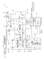
- Fig. 1 shows a configuration of a hydraulic controller configured to control a hydraulic actuator, according to Embodiment 1 of the present invention.
- a hydraulic controller 2 shown in Fig. 1 adopts a pump speed control method for the purpose of energy saving, noise reduction, and size reduction of a hydraulic system.
- the pump speed control method herein refers to a method of varying the rotational frequency of a hydraulic pump by means of a variable speed motor. For example, during a pressure holding state, the rotational frequency of the pump can be reduced by using the pump speed control method, and thereby energy can be saved.
- the hydraulic controller 2 also includes an accumulator 70 as an auxiliary power source for emergency use.
- the hydraulic controller 2 controls the driving of a single rod hydraulic cylinder 10 which serves as a hydraulic actuator, and also controls storing of pressure from a reversible pump 21 into the accumulator 70 as well as discharging of pressure oil stored in the accumulator 70 to the hydraulic cylinder 10.
- the hydraulic controller 2 is configured such that while the storing of pressure from the reversible pump 21 into the accumulator 70 is performed, pressure oil assuredly flows from the reversible pump 21 to both an oil system of a hydraulic drive circuit which serves to drive the hydraulic cylinder 10 and an oil system of a hydraulic pressure storage circuit which serves to store pressure in the accumulator 70, regardless of the magnitude of a load on and the operating speed of the hydraulic cylinder 10. It should be noted that the hydraulic controller 2 is also configured such that the hydraulic cylinder 10 is driven continuously regardless of presence or absence of pressure stored in the accumulator 70.
- the hydraulic controller 2 is configured such that when the storing of pressure from the reversible pump 21 into the accumulator 70 is completed, the destination of pressure oil supplied from the reversible pump 21 is limited to the oil system of the hydraulic drive circuit which serves to drive the hydraulic cylinder 10, such that the pressure oil is supplied from the reversible pump 21 to the hydraulic cylinder 10 in a minimum required amount.
- the overall configuration of the hydraulic controller 2 includes a pump unit 20a, a valve unit 30a, the accumulator 70, an oil tank 50, and a control board 60. It should be noted that the pump unit 20a, a part of the valve unit 30a, and the oil tank 50 constitute the hydraulic drive circuit according to the present invention, and also, the pump unit 20a, a part of the valve unit 30a, and the accumulator 70 constitute the hydraulic pressure storage circuit according to the present invention.
- the pump unit 20a includes the reversible pump 21, a variable speed motor 22, a rotational frequency detector 23, and check valves 24a and 24b.
- the reversible pump 21 includes two inlet/outlet ports, and is a hydraulic pump configured to reverse the flow direction of pressure oil by changing the rotation direction of its drive shaft. It should be noted that the reversible pump 21 also serves as a variable displacement pump, and includes a solenoid valve which is configured to switch a preset pump capacity based on an operation command from a controller 61 in order to minimize energy loss (i.e., reduce the pump capacity) during, for example, a pressure holding state (where no flow rate of the pump is required).
- An inlet/outlet port 210a which is one of the inlet/outlet ports of the reversible pump 21, is connected to one end of a main oil passage 301a.
- An inlet/outlet port 210b which is the other one of the inlet/outlet ports of the reversible pump 21, is connected to one end of a main oil passage 301 b.
- the other end of the main oil passage 301 a is connected to a head chamber 11 of the hydraulic cylinder 10.
- a main oil passage 301c which is brought into communication with or blocked from the main oil passage 301b by means of a solenoid operated switching valve 35, has its other end connected to a rod chamber 12 of the hydraulic cylinder 10.
- the main oil passage 301 a is disposed such that the main oil passage 301a extends from the inlet/outlet port 210a of the reversible pump 21 through a pilot check valve 31a to the head chamber 11 of the hydraulic cylinder 10.
- the main oil passage 301a serves to supply pressure oil discharged from the inlet/outlet port 210a to the head chamber 11 through the pilot check valve 31a, and to receive pressure oil that flows from the head chamber 11 toward the inlet/outlet port 210a through the pilot check valve 31a. That is, the main oil passage 301a can serves as both a first main oil passage and a second main oil passage according to the present invention.
- the main oil passage 301b is disposed such that the main oil passage 301b extends from the inlet/outlet port 210b of the reversible pump 21 to the solenoid operated switching valve 35.
- the main oil passage 301b serves to supply pressure oil discharged from the inlet/outlet port 210b to the rod chamber 12 through the solenoid operated switching valve 35 and a pilot check valve 31b, and to receive pressure oil that flows from the rod chamber 12 toward the inlet/outlet port 210b through the pilot check valve 31b and the solenoid operated switching valve 35.
- the main oil passage 301 b corresponds only to the first main oil passage according to the present invention, through which the pressure oil discharged from the inlet/outlet port 210b flows.
- the solenoid operated switching valve 35 is in an opened position, the main oil passage 301b can serve as both the first main oil passage and the second main oil passage according to the present invention.
- the main oil passage 301c is disposed such that the main oil passage 301c extends from the solenoid operated switching valve 35 through the pilot check valve 31b to the rod chamber 12 of the hydraulic cylinder 10.
- the main oil passage 301c serves to supply pressure oil to the rod chamber 12 through the pilot check valve 31b, and to receive pressure oil that flows from the rod chamber 12 toward the inlet/outlet port 210b through the pilot check valve 31b and the solenoid operated switching valve 35. That is, when the solenoid operated switching valve 35 is in a closed position, the main oil passage 301c corresponds only to the second main oil passage according to the present invention, through which the pressure oil is supplied to the hydraulic cylinder 10. On the other hand, when the solenoid operated switching valve 35 is in an opened position, the main oil passage 301c can serve as both the first main oil passage and the second main oil passage according to the present invention.
- the variable speed motor 22 is a motor configured to drive the drive shaft of the reversible pump 21, and is also an AC servomotor configured to switch its rotational frequency based on a rotational frequency command from a servo drive unit 62.
- the variable speed motor 22 includes the rotational frequency detector 23 which is configured as a pulse generator.
- a synchronous motor is used as the variable speed motor 22.
- an induction motor may be used as the variable speed motor 22.
- the rotational frequency detector 23 is not limited to a pulse generator but may be an encoder configured to detect a rotational position.
- the valve unit 30a includes a three-port hydraulic switching valve 32, a check valve 33a, relief valves 34a and 34b, and the solenoid operated switching valve 35 as components of the hydraulic drive circuit which drives the hydraulic cylinder 10.
- the hydraulic switching valve 32 has two inlet ports X and Y, and one outlet port Z.
- the hydraulic switching valve 32 is provided among the main oil passage 301a, the main oil passage 301 c, and the oil tank 50.
- the inlet port X of the hydraulic switching valve 32 is connected to the main oil passage 301 a.
- the inlet port Y is connected to the main oil passage 301 c, and the outlet port Z is connected to an oil passage leading to the oil tank 50.
- the inlet port Y and the outlet port Z are brought into communication with each other owing to the pressure of pressure oil supplied to the inlet port X
- the inlet port X and the outlet port Z are brought into communication with each other owing to the pressure of pressure oil supplied to the inlet port Y.
- the check valve 33a is provided on a drain oil passage (return oil passage) 501 between the oil tank 50 and the outlet port Z of the hydraulic switching valve 32. It should be noted that the inlet port of the check valve 33a is connected to the outlet port Z of the hydraulic switching valve 32, and the outlet port of the check valve 33a is connected to the oil tank 50. That is, the check valve 33a serves to prevent a backflow from the oil tank 50 to the outlet port Z of the hydraulic switching valve 32.
- the solenoid operated switching valve 35 alternatively allows or blocks communication between the main oil passage 301 b and the main oil passage 301 c.
- the solenoid operated switching valve 35 is a valve corresponding to a communication allowing/blocking device according to the present invention.
- the solenoid operated switching valve 35 is provided on the main oil passage 301c, and is positioned between the pilot check valve 31b and the inlet/outlet port 210b of the reversible pump 21.
- the solenoid operated switching valve 35 allows the main oil passage 301 b and the main oil passage 301c to be in communication with each other, thereby allowing pressure oil to flow in both directions between the inlet/outlet port 210b of the reversible pump 21 and the rod chamber 12 of the hydraulic cylinder 10 (i.e., ON state).
- the solenoid operated switching valve 35 serves to block the communication between the main oil passage 301 b and the main oil passage 301 c, thereby preventing pressure oil from flowing from the inlet/outlet port 210b of the reversible pump 21 to the rod chamber 12 of the hydraulic cylinder 10 (i.e., OFF state). It should be noted that the solenoid operated switching valve 35 shown in Fig. 1 is in the OFF state.
- the valve unit 30a includes a priority valve 36, a solenoid operated switching valve 37, pilot check valves 31 a, 31 b, and 31 c, and a pressure sensor 40 as components of a pressure storage drive circuit which uses the accumulator 70 and performs storing of hydraulic pressure.
- the priority valve 36 includes an inlet port 361, a priority port 362, and a bypass port 363.
- the priority valve 36 is provided on a pressure storage use oil passage 701 which extends from the main oil passage 301 b to the accumulator 70.
- the starting point of the pressure storage use oil passage 701 is positioned not on the main oil passage 301a but on the main oil passage 301 b. The reason for this is that in a case where the hydraulic cylinder 10 moves backward from the rod chamber 12 toward the head chamber 11, surplus oil tends to be produced, and such positioning of the starting point of the pressure storage use oil passage 701 as mentioned above makes it easier to obtain, from the surplus oil, a flow rate necessary for the storing of pressure in the accumulator 70.
- the starting point of the pressure storage use oil passage 701 may be positioned on the main oil passage 301 a. Also in this case, the same functions as those exerted in the case where the starting point of the pressure storage use oil passage 701 is positioned on the main oil passage 301b are still exerted.
- the priority valve 36 is configured such that, of the pressure oil that has flowed into the inlet port 361, regardless of the flow rate of the pressure oil that has flowed into the inlet port 361 (i.e., an inflow flow rate) and loads on the ports 362 and 363, the pressure oil at a flow rate set for the priority port 362 (i.e., a flow rate for storing of pressure) flows to the priority port 362 prior to the pressure oil at a surplus flow rate, which is a flow rate obtained by subtracting the flow rate for storing of pressure from the inflow flow rate, flows to the bypass port 363.
- a flow rate set for the priority port 362 i.e., a flow rate for storing of pressure
- the flow rate of pressure oil that flows into the inlet port 361 is 5 (L) per unit time (per minute)
- all of the 5 (L) of pressure oil that has flowed into the inlet port 361 flows out of the priority port 362 regardless of which of the load on the priority port 362 and the load on the bypass port 363 is greater.
- the solenoid operated switching valve 37 is configured to select oil passages extending from the pilot check valves 31 a, 31b, and 31c to the drain oil passage 501 at the time of using pressure oil stored in the accumulator 70 (i.e., OFF state), and to select oil passages extending from the pressure storage use oil passage 701 to the pilot check valves 31a, 31 b, and 31c at the time of driving the hydraulic cylinder 10 with the pump (i.e., ON state). It should be noted that the solenoid operated switching valve 37 shown in Fig. 1 is in the OFF state.
- the pilot check valve 31a is provided on the main oil passage 301 a, and is configured such that the inlet port of the pilot check valve 31a is disposed at the reversible pump 21 side and the outlet port of the pilot check valve 31 a is disposed at the hydraulic cylinder 10 side.
- the pilot port of the pilot check valve 31a is connected to the solenoid operated switching valve 37.
- the pilot check valve 31b is provided on the main oil passage 301c, and is configured such that the inlet port of the pilot check valve 31 b is disposed at the reversible pump 21 side and the outlet port of the pilot check valve 31b is disposed at the hydraulic cylinder 10 side.
- the pilot port of the pilot check valve 31 b is connected to the solenoid operated switching valve 37.
- the pilot check valves 31a and 31 b serve to block flows of pressure oil from the head chamber 11 and the rod chamber 12 of the hydraulic cylinder 10 toward the inlet/outlet ports 210a and 210b of the reversible pump 21.
- the pilot check valves 31a and 31b serve to allow pressure oil to flow in both directions between the head chamber 11 of the hydraulic cylinder 10 and the inlet/outlet port 210a of the reversible pump 21, and to flow in both directions between the rod chamber 12 of the hydraulic cylinder 10 and the inlet/outlet port 210b of the reversible pump 21.
- the pilot check valve 31c is provided between the accumulator 70 and the main oil passage 301a, and is configured such that the inlet port of the pilot check valve 31c is disposed at the accumulator 70 side and the outlet port of the pilot check valve 31c is disposed at the hydraulic cylinder 10 side.
- the pilot port of the pilot check valve 31c is connected to the solenoid operated switching valve 37.
- the pilot check valve 31c serves to allow the stored pressure oil to flow from the accumulator 70 toward the main oil passage 301a.
- the pilot check valve 31c serves to block a flow of the stored pressure oil from the accumulator 70 toward the main oil passage 301a.
- the pressure sensor 40 is provided on the pressure storage use oil passage 701, and is configured to indirectly detect pressure stored in the accumulator 70. It should be noted that, as an alternative, the pressure sensor 40 may be configured to directly detect pressure stored in the accumulator 70. Furthermore, a pressure switch may be used instead of the pressure sensor 40.
- valve unit 30a includes, for protection of the above-described configuration, the following components: relief valves 34a, 34b, 34c, and 34d; stop valves 38a and 38b; and throttles 39a, 39b, and 39c.
- the relief valves 34a, 34b, 34c, and 34d monitor the pressure of pressure oil that flows through their respective installation positions. Each relief valve is configured such that if the monitored pressure of the pressure oil is higher than a predetermined pressure, the relief valve serves to drain out the pressure oil into the oil tank 50 through the drain oil passage 501.
- the stop valves 38a and 38b are manually operated when, for example, the accumulator is under maintenance. At the time, the stop valves 38a and 38b serve to allow pressure oil to flow or block a flow of pressure oil.
- the throttles 39a, 39b, and 39c serve to limit the flow rate of pressure oil that flows through their respective installation positions.
- the control board 60 includes the controller 61 and the servo drive unit 62.
- the control board 60 performs hydraulic control of the entire hydraulic controller 2 (pump speed control, storing of pressure in and discharging of pressure from the accumulator, etc).
- the controller 61 includes at least a CPU and a memory.
- the controller 61 is configured to obtain, from an external device which is not shown, a position command specifying the rod position of the hydraulic cylinder 10, and to obtain rod position information about the hydraulic cylinder 10 which is detected by a position sensor 13, and to perform feedback control of the rod position of the hydraulic cylinder 10. Specifically, each time the controller 61 obtains the rod position information, the controller 61 generates a rotational frequency command for the variable speed motor 22, based on a deviation between the position command and the rod position information, and outputs the rotational frequency command to the servo drive unit 62.
- the controller 61 outputs an operation command to switch ON/OFF of the solenoid valve of the reversible pump 21.
- the capacity of the reversible pump 21 can be changed by the operation command. For example, in the case of high pressure such as at the time of storing pressure in the accumulator, the controller 61 selects a low pump capacity to reduce the torque of a motor, and in the case of low pressure such as at the time of normal operation, the controller 61 selects a high pump capacity to reduce the rotational frequency of the motor. Further, the controller 61 obtains pressure information about the accumulator 70 which is detected by the pressure sensor 40, and determines whether the storing of pressure in the accumulator 70 is necessary or not.
- the controller 61 monitors whether the pressure information detected by the pressure sensor 40 indicates a pressure higher than a predetermined pressure of the accumulator 70. If the pressure information detected by the pressure sensor 40 indicates a pressure lower than the predetermined pressure of the accumulator 70, the controller 61 determines that the storing of pressure in the accumulator 70 is necessary. If it is determined that the storing of pressure in the accumulator 70 is necessary, the controller 61 outputs an operation command to perform a predetermined switching operation of the solenoid operated switching valve 35.
- the servo drive unit 62 includes at least a CPU and a memory.
- the servo drive unit 62 is configured to obtain the rotational frequency command generated by the controller 61 and rotational frequency information detected by the rotational frequency detector 23, and to perform feedback control of the rotational frequency of the variable speed motor 22. Specifically, each time the servo drive unit 62 obtains the rotational frequency information, the servo drive unit 62 generates an inverter command based on a deviation between the rotational frequency command and the rotational frequency information, and outputs the inverter command to the variable speed motor 22.
- the accumulator 70 is a gas loaded accumulator.
- a spring loaded accumulator or a weight loaded accumulator may be used as the accumulator 70.
- the solenoid operated switching valve 35 allows, in response to an operation command from the controller 61, the main oil passage 301b and the main oil passage 301c to be in communication with each other, thereby allowing pressure oil to flow in both directions between the inlet/outlet port 210b of the reversible pump 21 and the rod chamber 12 of the hydraulic cylinder 10.
- the solenoid operated switching valve 37 selects, in response to an operation command from the controller 61, the oil passages extending from the pressure storage use oil passage 701 to the pilot check valves 31a, 31 b, and 31 c.
- the pilot check valves 31a and 31 b allow pressure oil to flow in both directions between the head chamber 11 of the hydraulic cylinder 10 and the inlet/outlet port 210a of the reversible pump 21, and in both directions between the rod chamber 12 of the hydraulic cylinder 10 and the inlet/outlet port 210b of the reversible pump 21.
- the pilot check valve 31c blocks a flow of pressure oil stored in the accumulator 70 toward the head chamber 11 of the hydraulic cylinder 10.
- the reversible pump 21 sucks, from the inlet/outlet port 210b, pressure oil in the rod chamber 12 through the pilot check valve 31b and the solenoid operated switching valve 35, and discharges the pressure oil from the inlet/outlet port 210a toward the head chamber 11 through the pilot check valve 31a.
- the pressure receiving area of the head chamber 11 is greater than the pressure receiving area of the rod chamber 12, the amount of pressure oil that returns from the rod chamber 12 is not the same as the amount of pressure oil discharged toward the head chamber 11.
- the pressure oil that is sucked into the inlet/outlet port 210b becomes insufficient.
- pressure oil stored in an auxiliary oil tank 50 is sucked into the inlet/outlet port 210b of the reversible pump 21 through the check valve 24b.
- the reversible pump 21 sucks, from the inlet/outlet port 210a, pressure oil in the head chamber 11 through the pilot check valve 31a, and discharges the pressure oil from the inlet/outlet port 210b toward the rod chamber 12 through the solenoid operated switching valve 35 and the pilot check valve 31b.
- the amount of pressure oil that returns from the head chamber 11 is greater than the amount of pressure oil discharged toward the rod chamber 12. Therefore, in order to drain out surplus oil from the head chamber 11 into the oil tank 50 through the drain oil passage 501, the hydraulic switching valve 32 brings the inlet port X and the outlet port Z into communication with each other.
- the time of using the accumulator 70 refers to, for example, a situation where pressure oil of which the pressure is stored in the accumulator 70 is used at a time of emergency such as a breakdown of the reversible pump 21 or the variable speed motor 22 or an occurrence of a power failure, or a situation where pressure oil of which the pressure is stored in the accumulator 70 is supplementarily used for increasing the flow rate of pressure oil discharged from the reversible pump 21.
- the present embodiment is intended for the former case.
- the present embodiment is intended for an emergency operation that is performed in a case where, for example, a breakdown of the reversible pump 21 has occurred while the rod of the hydraulic cylinder 10 is being moved forward from the head chamber 11 side toward the rod chamber 12 side.
- the emergency operation is an operation of fully moving forward the rod to the end of the rod chamber 12 by using pressure oil stored in the accumulator 70.
- the solenoid operated switching valve 37 selects, in response to an operation command from the controller 61, the oil passages extending from the pilot check valves 31a, 31b, and 31c to the drain oil passage 501. Accordingly, the pilot check valves 31a and 31b block a flow of pressure oil from the head chamber 11 of the hydraulic cylinder 10 toward the inlet/outlet port 210a of the reversible pump 21, and block a flow of pressure oil from the rod chamber 12 of the hydraulic cylinder 10 toward the inlet/outlet port 210b of the reversible pump 21.
- the pilot check valve 31c allows pressure oil stored in the accumulator 70 to flow toward the head chamber 11 of the hydraulic cylinder 10.
- the pressure oil stored in the accumulator 70 is supplied to the head chamber 11 of the hydraulic cylinder 10 through the throttle 39b, the stop valve 38a, and the pilot check valve 31 c.
- the emergency operation of forcibly moving the rod position of the hydraulic cylinder 10 to the end of the rod chamber 12 is started.
- the stop valve 38a, the pilot check valve 31c, the hydraulic cylinder 10, a check valve 33c, and the throttle 39a constitute a hydraulic loop circuit, in which pressure oil discharged from the rod chamber 12 is returned to the inlet port of the pilot check valve 31c through the check valve 33c and the throttle 39a. In this manner, the amount of oil supplied from the accumulator when the rod of the hydraulic cylinder 10 is moved is reduced.
- the solenoid operated switching valve 35 allows pressure oil to flow in both directions between the inlet/outlet port 210b of the reversible pump 21 and the rod chamber 12 of the hydraulic cylinder 10. Also, in response to an operation command from the controller 61, the solenoid operated switching valve 37 selects the oil passages extending from the pressure storage use oil passage 701 to the pilot check valves 31 a, 31 b, and 31 c.
- the controller 61 monitors whether pressure information detected by the pressure sensor 40 indicates a pressure higher than the predetermined pressure of the accumulator 70. If the pressure information detected by the pressure sensor 40 indicates a pressure lower than the predetermined pressure of the accumulator 70, the controller 61 determines that the storing of pressure in the accumulator 70 is necessary. Then, the controller 61 1 outputs, to the solenoid operated switching valve 35, an operation command to prevent pressure oil from flowing from the inlet/outlet port 210b of the reversible pump 21 to the rod chamber 12 of the hydraulic cylinder 10.
- the solenoid operated switching valve 35 blocks pressure oil discharged from the inlet/outlet port 210b of the reversible pump 21 so that the pressure oil will not directly flow toward the rod chamber 12 of the hydraulic cylinder 10, but allows the pressure oil discharged from the inlet/outlet port 210b to flow toward the inlet port 361 of the priority valve 36.
- pressure oil discharged from the inlet/outlet port 210b of the reversible pump 21 is caused to flow into the inlet port 361 of the priority valve 36.
- the pressure oil at the flow rate for storing of pressure which flow rate is set for the priority port 362
- the controller 61 determines that pressure information detected by the pressure sensor 40 indicates a pressure higher than the predetermined pressure, and that the storing of pressure in the accumulator 70 is to be ended.
- the controller 61 outputs, to the solenoid operated switching valve 35, an operation command to return to the state before the start of the pressure storing.
- the controller 61 allows pressure oil to flow in both directions between the inlet/outlet port 210b of the reversible pump 21 and the rod chamber 12 of the hydraulic cylinder 10. Consequently, as with before the start of the pressure storing, the operating pressure of the hydraulic cylinder 10 becomes lower than the pressure at the priority port 362 of the priority valve 36. As a result, a flow of pressure oil toward the priority valve 36 is ceased. In this manner, the storing of pressure in the accumulator 70 is ended.
- the priority valve 36 is disposed on the pressure storage use oil passage 701 extending from the main oil passage 301b to the accumulator 70. Accordingly, pressure oil at a stable flow rate can be used for the storing of pressure in the accumulator 70 regardless of loads on the priority port 362 and the bypass port 363 as well as the operating speed of the hydraulic cylinder 10. Moreover, a pump dedicated for the storing of pressure in the accumulator 70 is not necessary, which makes it possible to realize a compact size of the hydraulic controller 2, and to eventually realize a compact size of the hydraulic system.
- pressure oil is discharged from the inlet/outlet port 210b of the reversible pump 21 in a manner to compensate for a flow rate loss that corresponds to the flow rate of pressure oil that flows out of the priority port 362 of the priority valve 36 for the storing of pressure in the accumulator 70. Accordingly, pressure oil at the surplus flow rate, which is a flow rate obtained by subtracting the flow rate for the storing of pressure in the accumulator 70 from the flow rate at which the pressure oil is discharged from the inlet/outlet port 210b, assuredly occurs and flows through the bypass port 363 toward the rod chamber 12 of the hydraulic cylinder 10. Thus, stable control over the position of the hydraulic cylinder 10 can be performed regardless of presence or absence of pressure stored in the accumulator 70.
- Fig. 2 shows a configuration of a hydraulic controller configured to control a hydraulic actuator, according to Embodiment 2 of the present invention.
- a hydraulic controller 4 shown in Fig. 2 is different from the hydraulic controller 2 shown in Fig. 1 in that the priority valve 36 is replaced by a flow rate control mechanism which is a combination of a flow rate adjusting valve 364 and a pressure control valve 365.
- a valve unit 30b shown in Fig. 2 is the same as the valve unit 30a shown in Fig. 1 .
- the flow rate adjusting valve 364 is provided on the pressure storage use oil passage 701 between the main oil passage 301b and the accumulator 70.
- a rated flow rate (L) per unit time (per minute) is set for the flow rate adjusting valve 364.
- the flow rate of pressure oil flowing into the inlet port of the flow rate adjusting valve 364 is adjusted to the above rated flow rate per unit time, and then the pressure oil flows out of the flow rate adjusting valve 364 at the rated flow rate toward the accumulator 70.
- the pressure control valve 365 is provided on an oil passage that branches off from the pressure storage use oil passage 701 at a position between the main oil passage 301 b and the flow rate adjusting valve 364, and reaches the main oil passage 301c at a position between the pilot check valve 31b and the solenoid operated switching valve 35.
- the pressure control valve 365 causes pressure oil to flow out toward the rod chamber 12 of the hydraulic cylinder 10 at a surplus flow rate which is obtained by subtracting the rated flow rate of the flow rate adjusting valve 364 from the flow rate of the pressure oil flowing into the inlet port of the flow rate adjusting valve 364. That is, the branch passage, which includes the pressure control valve 365, serves as the bypass port 363 of the priority valve 36.
- the flow rate control mechanism which has the same functions as those of the priority valve 36, is used, and therefore, the same advantageous effects as those of Embodiment 1 can be obtained in the present embodiment.
- Fig. 3 shows a configuration of a hydraulic controller configured to control a hydraulic actuator, according to Embodiment 3 of the present invention.
- a hydraulic controller 6 shown in Fig. 3 is different from the hydraulic controller 2 shown in Fig. 1 in the following point: the hydraulic controller 2 shown in Fig. 1 is configured such that if surplus oil is produced when the hydraulic cylinder 10 is driven, the surplus oil is drained out into the oil tank 50, whereas the hydraulic controller 6 shown in Fig. 3 is configured such that pressure oil discharged from an oil pump 25 assuredly returns to the oil tank 50 through the hydraulic cylinder 10. As compared to the hydraulic controller 2 shown in Fig. 1 , in the hydraulic controller shown in Fig.
- the reversible pump 21 is replaced by the hydraulic pump 25 which is configured to discharge pressure oil in a single flow direction; the hydraulic switching valve 32 is replaced by a four-port solenoid operated switching valve 28; the check valve 33a, the relief valves 34a and 34b, and the check valves 24a and 24b are eliminated; and a relief valve 26 is newly provided for the purpose of protection.
- the other configurations in a pump unit 20b and a valve unit 30c shown in Fig. 3 are the same as those in the pump unit 20a and the valve unit 30a shown in Fig. 1 .
- the oil pump 25 has only one discharge port.
- the rotational frequency of the oil pump 25 is controlled by the variable speed motor 22 which is connected to the drive shaft of the oil pump 25.
- the oil pump 25 includes a solenoid valve configured to switch a preset pump capacity.
- the four-port solenoid operated switching valve 28 includes two ports X and Z disposed on the main oil passage 301 a, and two ports Y and W disposed on the main oil passage 301 b.
- the port X is connected to the inlet port of the pilot check valve 31 a, and the port Z is connected to the discharge port of the hydraulic pump 25.
- the port Y is connected to the solenoid operated switching valve 35, and the port W is connected to the oil tank 50.
- the four-port solenoid operated switching valve 28 is operated such that the port X and the port Z are connected to each other and the port Y and the port W are connected to each other.
- the four-port solenoid operated switching valve 28 is operated such that the port X and the port W are connected to each other and the port Y and the port Z are connected to each other.
- the relief valve 26 is a pressure control valve which drains out pressure oil discharged from the hydraulic pump 25 into the oil tank 50 in a case where the hydraulic pressure at the discharge port of the hydraulic pump 25 is higher than a predetermined pressure.
- Embodiment 1 the same advantageous effects as those of Embodiment 1 can be obtained even in the hydraulic system where pressure oil discharged from the oil pump 25 assuredly returns to the oil tank 50 through the hydraulic cylinder 10.
- the hydraulic controller according to the present invention is useful when applied as a hydraulic controller that is configured to control the rotational frequency of a hydraulic pump in order to supply pressure oil only in a necessary amount to a hydraulic actuator.
Applications Claiming Priority (2)
| Application Number | Priority Date | Filing Date | Title |
|---|---|---|---|
| JP2009257452A JP5368943B2 (ja) | 2009-11-10 | 2009-11-10 | 油圧制御装置 |
| PCT/JP2010/004401 WO2011058681A1 (ja) | 2009-11-10 | 2010-07-06 | 油圧制御装置 |
Publications (3)
| Publication Number | Publication Date |
|---|---|
| EP2500583A1 true EP2500583A1 (de) | 2012-09-19 |
| EP2500583A4 EP2500583A4 (de) | 2014-03-26 |
| EP2500583B1 EP2500583B1 (de) | 2015-04-01 |
Family
ID=43991356
Family Applications (1)
| Application Number | Title | Priority Date | Filing Date |
|---|---|---|---|
| EP10829649.2A Not-in-force EP2500583B1 (de) | 2009-11-10 | 2010-07-06 | Hydraulische drucksteuervorrichtung |
Country Status (6)
| Country | Link |
|---|---|
| US (1) | US9217446B2 (de) |
| EP (1) | EP2500583B1 (de) |
| JP (1) | JP5368943B2 (de) |
| KR (1) | KR101381072B1 (de) |
| CN (1) | CN102656372B (de) |
| WO (1) | WO2011058681A1 (de) |
Cited By (1)
| Publication number | Priority date | Publication date | Assignee | Title |
|---|---|---|---|---|
| IT202100000272A1 (it) * | 2021-01-08 | 2022-07-08 | Cnh Ind Italia Spa | Procedimento di controllo per selezionare automaticamente una modalità operativa di una macchina operatrice, corrispondente sistema di controllo e macchina operatrice comprendente il sistema di controllo |
Families Citing this family (32)
| Publication number | Priority date | Publication date | Assignee | Title |
|---|---|---|---|---|
| KR101862868B1 (ko) * | 2011-10-14 | 2018-07-06 | 에스케이이노베이션 주식회사 | 유압구동기를 이용한 유압제어장치 |
| CN105298782A (zh) * | 2011-11-07 | 2016-02-03 | 住友重机械工业株式会社 | 液压闭环系统 |
| JP5859279B2 (ja) * | 2011-11-07 | 2016-02-10 | 住友重機械工業株式会社 | 油圧閉回路システム |
| JP6009770B2 (ja) * | 2012-02-06 | 2016-10-19 | 住友重機械工業株式会社 | 油圧閉回路システム |
| JP5957735B2 (ja) * | 2012-06-28 | 2016-07-27 | 株式会社 神崎高級工機製作所 | コンバインの刈取部昇降用油圧回路 |
| JP5661084B2 (ja) | 2012-11-13 | 2015-01-28 | 株式会社神戸製鋼所 | 作業機械の油圧駆動装置 |
| CN103115028A (zh) * | 2013-03-12 | 2013-05-22 | 北京机械设备研究所 | 一种电液伺服执行器 |
| US9315968B2 (en) | 2013-09-17 | 2016-04-19 | Caterpillar Inc. | Hydraulic control system for machine |
| CN103672126B (zh) * | 2013-12-26 | 2016-06-22 | 重庆川仪自动化股份有限公司 | 一种电液执行器 |
| US11137000B2 (en) * | 2014-10-10 | 2021-10-05 | MEA Inc. | Self-contained energy efficient hydraulic actuator system |
| CN104454804B (zh) * | 2014-11-04 | 2016-07-06 | 中国建筑标准设计研究院有限公司 | 平开立转式防护密闭兼防淹门的液压系统 |
| AU2016231996B2 (en) * | 2015-03-13 | 2019-11-21 | Bae Systems Plc | Hydraulic system |
| KR102514523B1 (ko) * | 2015-12-04 | 2023-03-27 | 현대두산인프라코어 주식회사 | 건설기계의 유압 제어 장치 및 유압 제어 방법 |
| KR102510852B1 (ko) | 2015-12-04 | 2023-03-16 | 현대두산인프라코어 주식회사 | 건설기계의 유압 시스템 및 유압 제어 방법 |
| CN105947494B (zh) * | 2016-06-24 | 2019-01-08 | 博世力健环保科技(益阳)有限公司 | 一种移动式垃圾压缩箱尾门液压系统 |
| CN106089819B (zh) * | 2016-06-24 | 2019-01-25 | 博世力健环保科技(益阳)有限公司 | 一种移动式垃圾压缩箱液压系统 |
| KR101850114B1 (ko) * | 2017-01-09 | 2018-04-19 | 주식회사 제이에스티앤랩 | 엑츄에이터 제어밸브 교체용 바이패스/블록킹 장치 |
| JP6746511B2 (ja) * | 2017-01-31 | 2020-08-26 | 株式会社東芝 | 蒸気タービン弁駆動装置 |
| CN107013535B (zh) * | 2017-05-16 | 2018-07-06 | 山河智能装备股份有限公司 | 一种压力自匹配能量利用系统 |
| JP7043334B2 (ja) | 2018-04-27 | 2022-03-29 | 川崎重工業株式会社 | 液圧供給装置 |
| JP7182434B2 (ja) * | 2018-11-19 | 2022-12-02 | 川崎重工業株式会社 | 液圧システム |
| RU2702692C1 (ru) * | 2019-01-22 | 2019-10-09 | Андрей Александрович Павлов | Задатчик давления |
| US20220145774A1 (en) * | 2019-03-27 | 2022-05-12 | Salvatore Shifrin | Self contained hydraulic lock apparatus |
| JP7267879B2 (ja) * | 2019-09-06 | 2023-05-02 | 株式会社東芝 | 蒸気タービン弁駆動装置 |
| JP7297617B2 (ja) * | 2019-09-13 | 2023-06-26 | 日本ムーグ株式会社 | 電動油圧アクチュエータシステム、電動油圧アクチュエータシステムの油圧回路、及びそれを含む蒸気タービンシステム |
| CN110552928A (zh) * | 2019-09-24 | 2019-12-10 | 江苏徐工工程机械研究院有限公司 | 一种集成阀及浮动液压系统 |
| IT202000004117A1 (it) * | 2020-02-27 | 2021-08-27 | Atos Spa | Dispositivo di controllo di un sistema servo-pompa comprendente un’unità di auto-taratura e relativo metodo di auto-taratura |
| JP7408494B2 (ja) * | 2020-06-15 | 2024-01-05 | 株式会社東芝 | 蒸気タービン弁異常監視システム、蒸気タービン弁駆動装置、蒸気タービン弁装置および蒸気タービンプラント |
| KR20220127328A (ko) * | 2020-06-17 | 2022-09-19 | 히다치 겡키 가부시키 가이샤 | 건설 기계 |
| TWI755182B (zh) * | 2020-12-02 | 2022-02-11 | 武漢機械股份有限公司 | 節能液壓系統 |
| CN114295000B (zh) * | 2021-11-24 | 2023-12-15 | 北京航天发射技术研究所 | 一种可快速回收的高可靠性支撑液压系统及支撑方法 |
| WO2024048813A1 (ko) * | 2022-08-31 | 2024-03-07 | 볼보 컨스트럭션 이큅먼트 에이비 | 유압기계 |
Citations (4)
| Publication number | Priority date | Publication date | Assignee | Title |
|---|---|---|---|---|
| US3818801A (en) * | 1971-11-01 | 1974-06-25 | Hydron Inc | Fluid actuating mechanism having alternatively selectable fast and slow modes of operation |
| DE19913784A1 (de) * | 1999-03-26 | 2000-09-28 | Mannesmann Rexroth Ag | Lastfühlende hydraulische Steueranordnung für eine mobile Arbeitsmaschine |
| US20070251400A1 (en) * | 2003-10-09 | 2007-11-01 | Glass Arthur J | Platen Press |
| US20080110166A1 (en) * | 2006-11-14 | 2008-05-15 | Stephenson Dwight B | Energy recovery and reuse techniques for a hydraulic system |
Family Cites Families (19)
| Publication number | Priority date | Publication date | Assignee | Title |
|---|---|---|---|---|
| JPS5527510A (en) * | 1978-08-11 | 1980-02-27 | Tadano Tekkosho:Kk | Apparatus for accumulating pressure in accumulator |
| US4337620A (en) * | 1980-07-15 | 1982-07-06 | Eaton Corporation | Load sensing hydraulic system |
| DE3404598A1 (de) * | 1984-02-09 | 1985-08-14 | Mannesmann Rexroth GmbH, 8770 Lohr | Speicherladeventil mit druckabsicherung des speicherkreises |
| JPS63230497A (ja) * | 1987-03-20 | 1988-09-26 | 日産自動車株式会社 | 産業車両の荷役装置 |
| EP0440801B2 (de) * | 1989-06-26 | 1999-09-22 | Kabushiki Kaisha Komatsu Seisakusho | Hydraulische schaltung |
| FR2666787B1 (fr) * | 1990-09-19 | 1992-12-18 | Aerospatiale | Actionneur hydraulique a mode hydrostatique de fonctionnement de preference en secours, et systeme de commande de vol le comportant. |
| JPH0942212A (ja) * | 1995-05-24 | 1997-02-10 | Kobe Steel Ltd | 油圧制御装置 |
| JPH09196014A (ja) | 1996-01-12 | 1997-07-29 | Amada Co Ltd | 油圧回路 |
| US5826487A (en) * | 1997-02-20 | 1998-10-27 | Caterpillar Inc. | Pressure control for a pair of parallel hydraulic circuits |
| JP4678096B2 (ja) | 2001-04-27 | 2011-04-27 | コベルコ建機株式会社 | 建設機械の油圧回路 |
| JP3730141B2 (ja) * | 2001-07-04 | 2005-12-21 | 住友重機械工業株式会社 | 油圧回路 |
| JP3969068B2 (ja) * | 2001-11-21 | 2007-08-29 | コベルコ建機株式会社 | ハイブリッド作業機械のアクチュエータ駆動装置 |
| JP2003239903A (ja) * | 2002-02-18 | 2003-08-27 | Yaskawa Electric Corp | アクチュエータ駆動装置 |
| US6681568B2 (en) * | 2002-03-28 | 2004-01-27 | Caterpillar Inc | Fluid system for two hydraulic circuits having a common source of pressurized fluid |
| JP2004058204A (ja) | 2002-07-29 | 2004-02-26 | Shimada Corp | 切断油圧ユニットおよび該切断油圧ユニットを使用した長尺部材油圧切断装置並びにその油圧回路 |
| JP2007292133A (ja) | 2006-04-21 | 2007-11-08 | Toyota Motor Corp | ベルト式無段変速機 |
| US7908852B2 (en) * | 2008-02-28 | 2011-03-22 | Caterpillar Inc. | Control system for recovering swing motor kinetic energy |
| JP2009264525A (ja) * | 2008-04-28 | 2009-11-12 | Nabtesco Corp | 作動流体供給装置及び電動アクチュエータ |
| JP5354650B2 (ja) * | 2008-10-22 | 2013-11-27 | キャタピラー エス エー アール エル | 作業機械における油圧制御システム |
-
2009
- 2009-11-10 JP JP2009257452A patent/JP5368943B2/ja active Active
-
2010
- 2010-07-06 WO PCT/JP2010/004401 patent/WO2011058681A1/ja active Application Filing
- 2010-07-06 CN CN201080047935.5A patent/CN102656372B/zh not_active Expired - Fee Related
- 2010-07-06 KR KR1020127014052A patent/KR101381072B1/ko not_active IP Right Cessation
- 2010-07-06 EP EP10829649.2A patent/EP2500583B1/de not_active Not-in-force
- 2010-07-06 US US13/505,412 patent/US9217446B2/en not_active Expired - Fee Related
Patent Citations (4)
| Publication number | Priority date | Publication date | Assignee | Title |
|---|---|---|---|---|
| US3818801A (en) * | 1971-11-01 | 1974-06-25 | Hydron Inc | Fluid actuating mechanism having alternatively selectable fast and slow modes of operation |
| DE19913784A1 (de) * | 1999-03-26 | 2000-09-28 | Mannesmann Rexroth Ag | Lastfühlende hydraulische Steueranordnung für eine mobile Arbeitsmaschine |
| US20070251400A1 (en) * | 2003-10-09 | 2007-11-01 | Glass Arthur J | Platen Press |
| US20080110166A1 (en) * | 2006-11-14 | 2008-05-15 | Stephenson Dwight B | Energy recovery and reuse techniques for a hydraulic system |
Non-Patent Citations (1)
| Title |
|---|
| See also references of WO2011058681A1 * |
Cited By (2)
| Publication number | Priority date | Publication date | Assignee | Title |
|---|---|---|---|---|
| IT202100000272A1 (it) * | 2021-01-08 | 2022-07-08 | Cnh Ind Italia Spa | Procedimento di controllo per selezionare automaticamente una modalità operativa di una macchina operatrice, corrispondente sistema di controllo e macchina operatrice comprendente il sistema di controllo |
| EP4026953A1 (de) * | 2021-01-08 | 2022-07-13 | CNH Industrial Italia S.p.A. | Steuerungsverfahren zur automatischen auswahl eines betriebsmodus eines arbeitsfahrzeugs, entsprechendes steuerungssystem und arbeitsfahrzeug mit dem steuerungssystem |
Also Published As
| Publication number | Publication date |
|---|---|
| US20120240566A1 (en) | 2012-09-27 |
| US9217446B2 (en) | 2015-12-22 |
| EP2500583B1 (de) | 2015-04-01 |
| KR101381072B1 (ko) | 2014-04-04 |
| JP2011102608A (ja) | 2011-05-26 |
| KR20120080645A (ko) | 2012-07-17 |
| WO2011058681A1 (ja) | 2011-05-19 |
| EP2500583A4 (de) | 2014-03-26 |
| CN102656372B (zh) | 2015-01-07 |
| CN102656372A (zh) | 2012-09-05 |
| JP5368943B2 (ja) | 2013-12-18 |
Similar Documents
| Publication | Publication Date | Title |
|---|---|---|
| US9217446B2 (en) | Hydraulic controller | |
| US9926950B2 (en) | Hydraulic system for construction machinery | |
| KR101273086B1 (ko) | 하이브리드 건설 기계의 제어 장치 | |
| US8807155B2 (en) | Control device for hybrid construction machine | |
| US9187297B2 (en) | Hydraulic driving apparatus for working machine | |
| US9476437B2 (en) | Boom driving device | |
| US9037356B2 (en) | Control device for hybrid construction machine | |
| KR101390078B1 (ko) | 하이브리드 굴삭기 붐 구동시스템 및 그 제어방법 | |
| US9228599B2 (en) | Hydraulic circuit for construction equipment | |
| EP2706153B1 (de) | Schwenkende arbeitsmaschine | |
| US9650232B2 (en) | Hydraulic drive apparatus for work machine | |
| US9835187B2 (en) | Control system for construction machine | |
| JP2021532040A (ja) | 荷役車両用の油圧システム | |
| JP2014227949A (ja) | エンジン始動装置 | |
| JP2006206205A (ja) | リフティングマグネットを備えた作業機械の油圧制御回路 | |
| JP2015086802A (ja) | 建設機械の制御装置 | |
| CN110382786B (zh) | 工程机械的控制系统及工程机械的控制方法 | |
| EP3795843A1 (de) | Baumaschine | |
| JP2009299301A (ja) | ハイブリッド建設機械の制御装置 |
Legal Events
| Date | Code | Title | Description |
|---|---|---|---|
| PUAI | Public reference made under article 153(3) epc to a published international application that has entered the european phase |
Free format text: ORIGINAL CODE: 0009012 |
|
| 17P | Request for examination filed |
Effective date: 20120502 |
|
| AK | Designated contracting states |
Kind code of ref document: A1 Designated state(s): AL AT BE BG CH CY CZ DE DK EE ES FI FR GB GR HR HU IE IS IT LI LT LU LV MC MK MT NL NO PL PT RO SE SI SK SM TR |
|
| DAX | Request for extension of the european patent (deleted) | ||
| A4 | Supplementary search report drawn up and despatched |
Effective date: 20140221 |
|
| RIC1 | Information provided on ipc code assigned before grant |
Ipc: E02F 9/20 20060101ALI20140217BHEP Ipc: E02F 9/22 20060101ALI20140217BHEP Ipc: F15B 21/14 20060101ALI20140217BHEP Ipc: F15B 11/02 20060101AFI20140217BHEP Ipc: F15B 1/02 20060101ALI20140217BHEP |
|
| GRAP | Despatch of communication of intention to grant a patent |
Free format text: ORIGINAL CODE: EPIDOSNIGR1 |
|
| INTG | Intention to grant announced |
Effective date: 20141010 |
|
| GRAS | Grant fee paid |
Free format text: ORIGINAL CODE: EPIDOSNIGR3 |
|
| GRAA | (expected) grant |
Free format text: ORIGINAL CODE: 0009210 |
|
| AK | Designated contracting states |
Kind code of ref document: B1 Designated state(s): AL AT BE BG CH CY CZ DE DK EE ES FI FR GB GR HR HU IE IS IT LI LT LU LV MC MK MT NL NO PL PT RO SE SI SK SM TR |
|
| REG | Reference to a national code |
Ref country code: GB Ref legal event code: FG4D |
|
| REG | Reference to a national code |
Ref country code: CH Ref legal event code: EP |
|
| REG | Reference to a national code |
Ref country code: IE Ref legal event code: FG4D |
|
| REG | Reference to a national code |
Ref country code: DE Ref legal event code: R096 Ref document number: 602010023661 Country of ref document: DE Effective date: 20150513 |
|
| REG | Reference to a national code |
Ref country code: AT Ref legal event code: REF Ref document number: 719258 Country of ref document: AT Kind code of ref document: T Effective date: 20150515 |
|
| REG | Reference to a national code |
Ref country code: NL Ref legal event code: VDEP Effective date: 20150401 |
|
| REG | Reference to a national code |
Ref country code: AT Ref legal event code: MK05 Ref document number: 719258 Country of ref document: AT Kind code of ref document: T Effective date: 20150401 |
|
| REG | Reference to a national code |
Ref country code: LT Ref legal event code: MG4D |
|
| PG25 | Lapsed in a contracting state [announced via postgrant information from national office to epo] |
Ref country code: NL Free format text: LAPSE BECAUSE OF FAILURE TO SUBMIT A TRANSLATION OF THE DESCRIPTION OR TO PAY THE FEE WITHIN THE PRESCRIBED TIME-LIMIT Effective date: 20150401 |
|
| PG25 | Lapsed in a contracting state [announced via postgrant information from national office to epo] |
Ref country code: PT Free format text: LAPSE BECAUSE OF FAILURE TO SUBMIT A TRANSLATION OF THE DESCRIPTION OR TO PAY THE FEE WITHIN THE PRESCRIBED TIME-LIMIT Effective date: 20150803 Ref country code: FI Free format text: LAPSE BECAUSE OF FAILURE TO SUBMIT A TRANSLATION OF THE DESCRIPTION OR TO PAY THE FEE WITHIN THE PRESCRIBED TIME-LIMIT Effective date: 20150401 Ref country code: LT Free format text: LAPSE BECAUSE OF FAILURE TO SUBMIT A TRANSLATION OF THE DESCRIPTION OR TO PAY THE FEE WITHIN THE PRESCRIBED TIME-LIMIT Effective date: 20150401 Ref country code: HR Free format text: LAPSE BECAUSE OF FAILURE TO SUBMIT A TRANSLATION OF THE DESCRIPTION OR TO PAY THE FEE WITHIN THE PRESCRIBED TIME-LIMIT Effective date: 20150401 Ref country code: ES Free format text: LAPSE BECAUSE OF FAILURE TO SUBMIT A TRANSLATION OF THE DESCRIPTION OR TO PAY THE FEE WITHIN THE PRESCRIBED TIME-LIMIT Effective date: 20150401 Ref country code: CZ Free format text: LAPSE BECAUSE OF FAILURE TO SUBMIT A TRANSLATION OF THE DESCRIPTION OR TO PAY THE FEE WITHIN THE PRESCRIBED TIME-LIMIT Effective date: 20150401 Ref country code: NO Free format text: LAPSE BECAUSE OF FAILURE TO SUBMIT A TRANSLATION OF THE DESCRIPTION OR TO PAY THE FEE WITHIN THE PRESCRIBED TIME-LIMIT Effective date: 20150701 |
|
| PGFP | Annual fee paid to national office [announced via postgrant information from national office to epo] |
Ref country code: DE Payment date: 20150822 Year of fee payment: 6 Ref country code: GB Payment date: 20150721 Year of fee payment: 6 |
|
| PG25 | Lapsed in a contracting state [announced via postgrant information from national office to epo] |
Ref country code: LV Free format text: LAPSE BECAUSE OF FAILURE TO SUBMIT A TRANSLATION OF THE DESCRIPTION OR TO PAY THE FEE WITHIN THE PRESCRIBED TIME-LIMIT Effective date: 20150401 Ref country code: IS Free format text: LAPSE BECAUSE OF FAILURE TO SUBMIT A TRANSLATION OF THE DESCRIPTION OR TO PAY THE FEE WITHIN THE PRESCRIBED TIME-LIMIT Effective date: 20150801 Ref country code: AT Free format text: LAPSE BECAUSE OF FAILURE TO SUBMIT A TRANSLATION OF THE DESCRIPTION OR TO PAY THE FEE WITHIN THE PRESCRIBED TIME-LIMIT Effective date: 20150401 Ref country code: GR Free format text: LAPSE BECAUSE OF FAILURE TO SUBMIT A TRANSLATION OF THE DESCRIPTION OR TO PAY THE FEE WITHIN THE PRESCRIBED TIME-LIMIT Effective date: 20150702 |
|
| REG | Reference to a national code |
Ref country code: DE Ref legal event code: R097 Ref document number: 602010023661 Country of ref document: DE |
|
| PG25 | Lapsed in a contracting state [announced via postgrant information from national office to epo] |
Ref country code: DK Free format text: LAPSE BECAUSE OF FAILURE TO SUBMIT A TRANSLATION OF THE DESCRIPTION OR TO PAY THE FEE WITHIN THE PRESCRIBED TIME-LIMIT Effective date: 20150401 Ref country code: EE Free format text: LAPSE BECAUSE OF FAILURE TO SUBMIT A TRANSLATION OF THE DESCRIPTION OR TO PAY THE FEE WITHIN THE PRESCRIBED TIME-LIMIT Effective date: 20150401 |
|
| PLBE | No opposition filed within time limit |
Free format text: ORIGINAL CODE: 0009261 |
|
| STAA | Information on the status of an ep patent application or granted ep patent |
Free format text: STATUS: NO OPPOSITION FILED WITHIN TIME LIMIT |
|
| PG25 | Lapsed in a contracting state [announced via postgrant information from national office to epo] |
Ref country code: SK Free format text: LAPSE BECAUSE OF FAILURE TO SUBMIT A TRANSLATION OF THE DESCRIPTION OR TO PAY THE FEE WITHIN THE PRESCRIBED TIME-LIMIT Effective date: 20150401 Ref country code: RO Free format text: LAPSE BECAUSE OF NON-PAYMENT OF DUE FEES Effective date: 20150401 Ref country code: MC Free format text: LAPSE BECAUSE OF FAILURE TO SUBMIT A TRANSLATION OF THE DESCRIPTION OR TO PAY THE FEE WITHIN THE PRESCRIBED TIME-LIMIT Effective date: 20150401 Ref country code: PL Free format text: LAPSE BECAUSE OF FAILURE TO SUBMIT A TRANSLATION OF THE DESCRIPTION OR TO PAY THE FEE WITHIN THE PRESCRIBED TIME-LIMIT Effective date: 20150401 |
|
| REG | Reference to a national code |
Ref country code: CH Ref legal event code: PL |
|
| 26N | No opposition filed |
Effective date: 20160105 |
|
| PG25 | Lapsed in a contracting state [announced via postgrant information from national office to epo] |
Ref country code: LU Free format text: LAPSE BECAUSE OF FAILURE TO SUBMIT A TRANSLATION OF THE DESCRIPTION OR TO PAY THE FEE WITHIN THE PRESCRIBED TIME-LIMIT Effective date: 20150706 |
|
| REG | Reference to a national code |
Ref country code: IE Ref legal event code: MM4A |
|
| PG25 | Lapsed in a contracting state [announced via postgrant information from national office to epo] |
Ref country code: IT Free format text: LAPSE BECAUSE OF FAILURE TO SUBMIT A TRANSLATION OF THE DESCRIPTION OR TO PAY THE FEE WITHIN THE PRESCRIBED TIME-LIMIT Effective date: 20150401 Ref country code: LI Free format text: LAPSE BECAUSE OF NON-PAYMENT OF DUE FEES Effective date: 20150731 Ref country code: CH Free format text: LAPSE BECAUSE OF NON-PAYMENT OF DUE FEES Effective date: 20150731 |
|
| REG | Reference to a national code |
Ref country code: FR Ref legal event code: ST Effective date: 20160331 |
|
| PG25 | Lapsed in a contracting state [announced via postgrant information from national office to epo] |
Ref country code: FR Free format text: LAPSE BECAUSE OF NON-PAYMENT OF DUE FEES Effective date: 20150731 Ref country code: SI Free format text: LAPSE BECAUSE OF FAILURE TO SUBMIT A TRANSLATION OF THE DESCRIPTION OR TO PAY THE FEE WITHIN THE PRESCRIBED TIME-LIMIT Effective date: 20150401 |
|
| PG25 | Lapsed in a contracting state [announced via postgrant information from national office to epo] |
Ref country code: IE Free format text: LAPSE BECAUSE OF NON-PAYMENT OF DUE FEES Effective date: 20150706 |
|
| PG25 | Lapsed in a contracting state [announced via postgrant information from national office to epo] |
Ref country code: BE Free format text: LAPSE BECAUSE OF FAILURE TO SUBMIT A TRANSLATION OF THE DESCRIPTION OR TO PAY THE FEE WITHIN THE PRESCRIBED TIME-LIMIT Effective date: 20150401 |
|
| REG | Reference to a national code |
Ref country code: DE Ref legal event code: R119 Ref document number: 602010023661 Country of ref document: DE |
|
| GBPC | Gb: european patent ceased through non-payment of renewal fee |
Effective date: 20160706 |
|
| PG25 | Lapsed in a contracting state [announced via postgrant information from national office to epo] |
Ref country code: MT Free format text: LAPSE BECAUSE OF FAILURE TO SUBMIT A TRANSLATION OF THE DESCRIPTION OR TO PAY THE FEE WITHIN THE PRESCRIBED TIME-LIMIT Effective date: 20150401 |
|
| PG25 | Lapsed in a contracting state [announced via postgrant information from national office to epo] |
Ref country code: DE Free format text: LAPSE BECAUSE OF NON-PAYMENT OF DUE FEES Effective date: 20170201 |
|
| PG25 | Lapsed in a contracting state [announced via postgrant information from national office to epo] |
Ref country code: SM Free format text: LAPSE BECAUSE OF FAILURE TO SUBMIT A TRANSLATION OF THE DESCRIPTION OR TO PAY THE FEE WITHIN THE PRESCRIBED TIME-LIMIT Effective date: 20150401 Ref country code: GB Free format text: LAPSE BECAUSE OF NON-PAYMENT OF DUE FEES Effective date: 20160706 Ref country code: HU Free format text: LAPSE BECAUSE OF FAILURE TO SUBMIT A TRANSLATION OF THE DESCRIPTION OR TO PAY THE FEE WITHIN THE PRESCRIBED TIME-LIMIT; INVALID AB INITIO Effective date: 20100706 Ref country code: BG Free format text: LAPSE BECAUSE OF FAILURE TO SUBMIT A TRANSLATION OF THE DESCRIPTION OR TO PAY THE FEE WITHIN THE PRESCRIBED TIME-LIMIT Effective date: 20150401 |
|
| PG25 | Lapsed in a contracting state [announced via postgrant information from national office to epo] |
Ref country code: CY Free format text: LAPSE BECAUSE OF FAILURE TO SUBMIT A TRANSLATION OF THE DESCRIPTION OR TO PAY THE FEE WITHIN THE PRESCRIBED TIME-LIMIT Effective date: 20150401 Ref country code: SE Free format text: LAPSE BECAUSE OF FAILURE TO SUBMIT A TRANSLATION OF THE DESCRIPTION OR TO PAY THE FEE WITHIN THE PRESCRIBED TIME-LIMIT Effective date: 20150401 |
|
| PG25 | Lapsed in a contracting state [announced via postgrant information from national office to epo] |
Ref country code: TR Free format text: LAPSE BECAUSE OF FAILURE TO SUBMIT A TRANSLATION OF THE DESCRIPTION OR TO PAY THE FEE WITHIN THE PRESCRIBED TIME-LIMIT Effective date: 20150401 |
|
| PG25 | Lapsed in a contracting state [announced via postgrant information from national office to epo] |
Ref country code: MK Free format text: LAPSE BECAUSE OF FAILURE TO SUBMIT A TRANSLATION OF THE DESCRIPTION OR TO PAY THE FEE WITHIN THE PRESCRIBED TIME-LIMIT Effective date: 20150401 |
|
| PG25 | Lapsed in a contracting state [announced via postgrant information from national office to epo] |
Ref country code: AL Free format text: LAPSE BECAUSE OF FAILURE TO SUBMIT A TRANSLATION OF THE DESCRIPTION OR TO PAY THE FEE WITHIN THE PRESCRIBED TIME-LIMIT Effective date: 20150401 |