EP2500489A2 - Sun protection system - Google Patents
Sun protection system Download PDFInfo
- Publication number
- EP2500489A2 EP2500489A2 EP12154230A EP12154230A EP2500489A2 EP 2500489 A2 EP2500489 A2 EP 2500489A2 EP 12154230 A EP12154230 A EP 12154230A EP 12154230 A EP12154230 A EP 12154230A EP 2500489 A2 EP2500489 A2 EP 2500489A2
- Authority
- EP
- European Patent Office
- Prior art keywords
- awning
- cassette
- drop rail
- sunshade
- arms
- Prior art date
- Legal status (The legal status is an assumption and is not a legal conclusion. Google has not performed a legal analysis and makes no representation as to the accuracy of the status listed.)
- Withdrawn
Links
Images


Classifications
-
- E—FIXED CONSTRUCTIONS
- E04—BUILDING
- E04F—FINISHING WORK ON BUILDINGS, e.g. STAIRS, FLOORS
- E04F10/00—Sunshades, e.g. Florentine blinds or jalousies; Outside screens; Awnings or baldachins
- E04F10/02—Sunshades, e.g. Florentine blinds or jalousies; Outside screens; Awnings or baldachins of flexible canopy materials, e.g. canvas ; Baldachins
- E04F10/06—Sunshades, e.g. Florentine blinds or jalousies; Outside screens; Awnings or baldachins of flexible canopy materials, e.g. canvas ; Baldachins comprising a roller-blind with means for holding the end away from a building
- E04F10/0611—Sunshades, e.g. Florentine blinds or jalousies; Outside screens; Awnings or baldachins of flexible canopy materials, e.g. canvas ; Baldachins comprising a roller-blind with means for holding the end away from a building with articulated arms supporting the movable end of the blind for deployment of the blind
- E04F10/0618—Sunshades, e.g. Florentine blinds or jalousies; Outside screens; Awnings or baldachins of flexible canopy materials, e.g. canvas ; Baldachins comprising a roller-blind with means for holding the end away from a building with articulated arms supporting the movable end of the blind for deployment of the blind whereby the pivot axis of the articulation is perpendicular to the roller
-
- E—FIXED CONSTRUCTIONS
- E04—BUILDING
- E04F—FINISHING WORK ON BUILDINGS, e.g. STAIRS, FLOORS
- E04F10/00—Sunshades, e.g. Florentine blinds or jalousies; Outside screens; Awnings or baldachins
- E04F10/02—Sunshades, e.g. Florentine blinds or jalousies; Outside screens; Awnings or baldachins of flexible canopy materials, e.g. canvas ; Baldachins
- E04F10/06—Sunshades, e.g. Florentine blinds or jalousies; Outside screens; Awnings or baldachins of flexible canopy materials, e.g. canvas ; Baldachins comprising a roller-blind with means for holding the end away from a building
- E04F10/0611—Sunshades, e.g. Florentine blinds or jalousies; Outside screens; Awnings or baldachins of flexible canopy materials, e.g. canvas ; Baldachins comprising a roller-blind with means for holding the end away from a building with articulated arms supporting the movable end of the blind for deployment of the blind
-
- E—FIXED CONSTRUCTIONS
- E04—BUILDING
- E04F—FINISHING WORK ON BUILDINGS, e.g. STAIRS, FLOORS
- E04F10/00—Sunshades, e.g. Florentine blinds or jalousies; Outside screens; Awnings or baldachins
- E04F10/02—Sunshades, e.g. Florentine blinds or jalousies; Outside screens; Awnings or baldachins of flexible canopy materials, e.g. canvas ; Baldachins
- E04F10/06—Sunshades, e.g. Florentine blinds or jalousies; Outside screens; Awnings or baldachins of flexible canopy materials, e.g. canvas ; Baldachins comprising a roller-blind with means for holding the end away from a building
- E04F10/0692—Front bars
- E04F10/0696—Front bars with means to attach an auxiliary screen
Definitions
- the invention relates to an awning with additional sun protection and an additional sun protection for an awning.
- the awning comprises a frame pivotable about a horizontal axis. Between the frame and the building ropes are stretched, on which run eyelets, which carry a curtain.
- the utility model G 84 30 086 U1 discloses an awning with a fabric and an associated support to which the fabric is anchored.
- the carrier is formed by a cylinder profile with two longitudinal bores. The longitudinal bores are slotted towards the cylinder jacket.
- the awning material is anchored with a piping in one of these holes. The other hole may carry a vertically hanging curtain.
- the DE 37 44 590 C1 discloses an awning with obliquely arranged rails, on which support rods of a fabric curtain are suspended movably along the rails.
- the mounting rails carry the fabric curtain, which is initially horizontal or light along the mounting rails sloping downwards and then hanging down from the free end of the mounting rails down.
- the DE 200 09 461 U1 discloses an anti-glare curtain formed in the manner of a vertically oriented articulated arm awning. From a vertically oriented winding shaft, an anti-glare curtain extends like a wall to a vertical Ausschubstab whose lower end is supported by a wheel on the ground. Between the housing of the winding shaft and the extension rod articulated arms are arranged.
- the DE 1 896 00 U1 discloses a sunshade that is to be moved vertically in front of a window and, if necessary, to fold on a circular arc away from it.
- a side awning which includes an arm to be folded away from a house wall about a vertical axis.
- This arm carries a curtain, for example in the form of a Roman blind.
- awnings and possibly an additional sunscreen is a persistent problem.
- Several different requirements have to be united with each other, whose individual solutions lead in different directions.
- the system is designed to be easy to use, easy to retrofit, and robust.
- the removal of the awning fabric under the action of a spring bias may be resiliently biased away from the building.
- the winding shaft may be provided with a manual drive or a motor drive which rotates the winding shaft in the winding or in the unwinding direction.
- the guide profile has a rectangular guide channel, for example, in which one or more rollers of the awning arms run.
- the guide profile may be a longitudinally slotted rectangular hollow profile.
- the basic concept of the awning arms swiveling away from the building approximately horizontally provides a simple and clear, yet robust, basic structure, with which the awning fabric can be taut without any problem. Even with moderate spring forces the drop rail can absorb high Tuchzug material. When the angle included between the drop rail and the awning arms approaches a right angle, despite decreasing, acting on the awning arms Swinging moment ever greater Tuchzug will be absorbed.
- the storage of the ends of the awning arms in or on the drop rail by wheels or rollers avoids unnecessary friction and thus facilitates the complete swinging out of the awning arms despite relatively low, easily manageable spring forces.
- the awning can be equipped with an additional sunscreen.
- This can for example be attached to the drop rail or on the awning arm.
- it is housed in a cassette housing, wherein the cassette housing preferably has only at its two end faces fastening devices for attachment to the awning.
- This concept allows the variable use of the sunshade alternatively on the drop rail or on the awning arm. This in particular if the fastening devices allow a certain pivotal movement of the cassette against its associated suspension, at least in principle. While one end of the cassette is located at the pivotal mounting at a fixed height, the other end of the cassette can pivot up and down.
- the cassette can be attached to the in use and in the building-splayed state, preferably slightly obliquely downwardly extending, awning arm, wherein one of the ends of the cassette is pivotable and the other Height adjustable is mounted on the awning arm.
- For height adjustment can serve a lockable spring winding apparatus, which has been found to be particularly user-friendly.
- the cassette according to the invention can, in particular by the nature of its attachment optionally on the drop rail or on the preferably rigid, i. hingeless awning arms are attached.
- awning 11 which carries an additional sunshade 12. This is, as easily recognizable, attached laterally. Additional additional sunshades 13, 14 may be attached to the end of the awning 11 away from the building wall 10. While the awning 11 extends approximately horizontally or slightly sloping away from the building wall 10, to overshadow a place, such as a seat, appropriate cloths or sheets of additional sunscreen 12, 13, 14, preferably vertically from the awning 11 down.
- the near-building end 16 is fixed to a winding shaft 17.
- the other end 18 is attached to a drop rail 19, e.g. taken in a corresponding Kedernut.
- the drop rail 19 is preferably arranged horizontally and parallel to the winding shaft 17.
- the drop rail 19 is made of, for example FIG. 3 visible awning arms 20, 21 worn, which is taken on the building wall 10 in corresponding bearings 22, 23 and pivotally mounted about a vertical or slightly inclined to the vertical axis of rotation 24.
- the bearing 22 is arranged below a winding shaft 17 receiving awning box 25. It may be connected to the building wall 10 and / or the awning box 24.
- the awning box 24 and the storage for the awning arms 20, 21 form a structural unit that is hung in pre-assembled consoles.
- FIG. 4 illustrates the storage 22 separately.
- the awning arm 20 is biased by a spring 55 in the pivoting direction away from the wall 10.
- the spring 55 may be a tension spring, which is outside the pivot axis 24 engages an end piece 56 of the arm 20 and thus generates a pivoting moment for the awning arm 20 (21).
- roller assembly 26, 27, in FIG. 1 indicated schematically and better off FIG. 5 is apparent. It comprises at least one, preferably at least two rollers 28, 29, which are preferably rotatably mounted about an approximately perpendicular axis 30. They are supported by a tab 31 extending from the end of the awning arm 20, 21 away from the respective support 22, 23.
- the drop rail 19 is formed as a guide profile. For this purpose, it has, for example, a longitudinally extending through the drop rail 19 interior 32, which, as shown, may be rectangular or otherwise shaped. He is on its building wall 10 facing side accessible through a slot 33 through which the tab 31 extends therethrough.
- the roller assembly 26 is preferably disposed in the interior 32 and may run along the drop rail 19. The vertical boundary walls of the interior 32 form tracks for the rollers 27, 28th
- the tab 31 is preferably part of a fitting 34, for example made of metal, which is attached to the free end of the awning arm 20 (or 21).
- the fitting 34 is separately in FIGS. 6 and 7 illustrated. As can be seen, it may have a downwardly extending extension 35, which may serve to secure the additional sunshade 12.
- an opening 36 may be formed in the extension 35, for example in the form of a rectangular slot.
- the opening 36 at the bottom limiting web 37 is in cross section (see FIG. 7 ) is preferably rounded, for example circular. He is horizontal arranged and thereby formed a horizontal pivot bearing for the additional sun protection 12th
- a downwardly extending extension 38 which is also the storage of an additional sunscreen (13,14 in FIG. 2 ) serves.
- This extension 38 may be formed, for example, as a straight extension of the front wall of the interior 32 down.
- one or more brackets 39 may be screwed, which serve to receive the respective sunshade 13 or 14 and to have a slot-like passage 40.
- An end-side end piece of the drop rail 19 can also serve as a support for mounting the sunshade 13 or 14.
- a Kedernut 41 for receiving the in FIG. 2 schematically indicated flounces 42.
- the additional sunshade 12 preferably coincides with the sunshade 13, 14.
- the uniform sunshade 12, 13, 14 can optionally be attached to the drop rail 19 or the awning arms 20, 21.
- the following description of the sunshade 12 applies equally to the other sunshades 13 and 14.
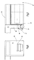
- FIGS. 7 and 8th shows a cassette 43, which is designed as a hollow box, as a closed end tube profile or downwardly open U-profile.
- a winding shaft 44 is housed with a wound roller blind is provided and forms a downwardly extendable roller blind.
- other shading means such as a horizontal or vertical blind slat curtain, a folding blind or the like may be accommodated in the cassette 43.
- the cassette 43 is only at its two ends 45, 46 ( FIGS. 7 and 8th ) provided with fastening means 47, 48, preferably in the form downwardly curved hook.
- the hooks are preferably formed by downwardly curved flat profiles with a rectangular cross-section.
- the rectangular cross section corresponds to a necessary clearance the cross section of the opening 36th
- the hook 48 While the hook 47 is hooked into the opening 36 of the fitting 34, the hook 48 is connected to a height-adjustable suspension 49.
- a receiving lug 50 in which the hook 48 engages, wherein the suspension lug 50 is supported by a pulling means 51.
- the traction means 51 may be a rope, a wire or a band, for example a plastic band or preferably a steel band.
- This is a, for example, arranged on the awning arm 20 or 22 winding device 52 assigned, this meadow by means of a locking device is preferably blockable. It has a take-up reel 53, which is biased by a not further illustrated spring in the winding direction.
- a release button 54 may be provided to release the locking device to allow rotation of the reel spool 53.
- the locking device may be formed by a slider which acts on the reel spool 53 to lock it.
- the trigger button 54 may be manually operable.
- the winding moment acting on the reel spool 53 is so great that the tensile force on the traction means 51 is the weight of the sunshade 12 easily overcomes.
- the force exerted by the awning arms 20, 21 on the drop rail 19 away from the building wall 10 force increases despite decreasing spring force due to the change in angle of the angle between the awning arms and the drop rail or remains at least constant.
- the awning 1 is extended. This condition is in the Figures 1 and 2 illustrated. It can now be activated, for example, the additional lateral sunshade 12.
- FIG. 8 first brought the cassette 43 in horizontal position. It is sufficient to pull the cartridge 12 at its building end down. A built-in cassette 43 spirit level can facilitate the horizontal adjustment of the cassette 12. Once the horizontal position has been reached, the blind placed in the cassette 43, for example a blind or the like, can be extended.
- the awning can be retracted at any time. If the lateral sunshade 12 is still in the pull-out position, it does not hinder the retraction of the awning. Thus, for example, a motor-operated awning can be retracted automatically at any time, without causing damage or danger.
- the winding device 52 it is possible by the winding device 52 to find a particularly secure stowed position.
- the curtain for example, the blind, wound on the winding shaft 44.
- the sunscreen of the sunscreen 12 is thus completely absorbed by the cartridge 43 as possible.
- the trigger button 54 is actuated.
- the reel spool 53 is released and the right end 46 of the cassette 43 is pulled upward until it abuts against the awning arm 20 or 22.
- the awning 10 can now be retracted by winding up the awning fabric 15 as described above.
- the awning according to the invention has two awning arms, which are held on the drop rail in linear guides.
- a sunshade 12, 13, 14 is provided, the cartridge housing is held only at its two ends 45, 46 by suitable fastening means.
- at least one of the two ends about a horizontal axis (web 37) is pivotally supported, while the other end 46 can be adjusted by a height-adjustable suspension 49 up or down.
- the operation is very easy and safe.
Landscapes
- Engineering & Computer Science (AREA)
- Architecture (AREA)
- Civil Engineering (AREA)
- Structural Engineering (AREA)
- Building Awnings And Sunshades (AREA)
Abstract
Description
Die Erfindung betrifft eine Markise mit zusätzlichem Sonnenschutz sowie einen zusätzlichen Sonnenschutz für eine Markise.The invention relates to an awning with additional sun protection and an additional sun protection for an awning.
In der Praxis tritt immer wieder der Wunsch auf, an Markisen einen zusätzlichen Sonnen-, Wind- oder Sichtschutz anzubringen, der von der Markise ungefähr vertikal herabhängt.In practice, there is always the desire to attach to awnings an additional sun, wind or visual protection, which depends on the awning approximately vertically.
Dazu offenbart die
Weiter offenbart das Gebrauchsmuster G 84 30 086 U1 eine Markise mit einer Stoffbahn und einem zugehörigen Träger, an dem die Stoffbahn verankert ist. Der Träger wird durch ein Zylinderprofil mit zwei Längsbohrungen gebildet. Die Längsbohrungen sind zum Zylindermantel hin geschlitzt. Die Markisenstoffbahn ist mit einem Keder in einer dieser Bohrungen verankert. Die andere Bohrung kann einen vertikal herabhängenden Vorhang tragen.Next, the utility model G 84 30 086 U1 discloses an awning with a fabric and an associated support to which the fabric is anchored. The carrier is formed by a cylinder profile with two longitudinal bores. The longitudinal bores are slotted towards the cylinder jacket. The awning material is anchored with a piping in one of these holes. The other hole may carry a vertically hanging curtain.
Die
Die
Die
Weiter offenbart die
Die Gestaltung von Markisen und gegebenenfalls einem zusätzlichen Sonnenschutz ist ein persistierendes Problem. Es müssen mehrere verschiedene Forderungen miteinander vereint werden, deren Einzellösungen in verschiedene Richtungen führen. Zum Beispiel soll das System einfach zu handhaben, leicht nachzurüsten und robust sein.The design of awnings and possibly an additional sunscreen is a persistent problem. Several different requirements have to be united with each other, whose individual solutions lead in different directions. For example, the system is designed to be easy to use, easy to retrofit, and robust.
Es ist Aufgabe der Erfindung, eine Markise sowie einen Sonnenschutz anzugeben, die diesen Anforderungen gerecht werden.It is an object of the invention to provide an awning and a sunshade that meet these requirements.
Diese Aufgabe wird mit der Markise nach Anspruch 1 und/oder dem Sonnenschutz für eine Markise nach Anspruch 5 gelöst:
- Die erfindungsgemäße Markise ist besonders robust. Sie umfasst zwei Markisenarme, die gebäudeseitig an Gelenken um vertikale Achsen schwenkbar gelagert sind. Die vom Gebäude weg liegenden Enden der Markisenarme laufen in oder an einem Führungsprofil der Fallschiene, die ihrerseits das Markisentuch auszieht. Das Markisentuch ist mit seinem gebäudeseitigen Ende von einer Wickelwelle aufgenommen. Die Fallschiene und die Wickelwelle spannen das Markisentuch zwischen einander.
- The awning according to the invention is particularly robust. It comprises two awning arms, which are pivotally mounted at the joints on joints around vertical axes. The ends of the awning arms lying away from the building run in or on a guide profile of the drop rail, which in turn pulls out the awning cloth. The awning cloth is taken with its building-side end of a winding shaft. The drop rail and the winding shaft clamp the awning cloth between each other.
Vorzugsweise erfolgt das Ausziehen des Markisentuchs unter der Wirkung einer Federvorspannung. Zum Beispiel können die Markisenarme von dem Gebäude weg federnd vorgespannt sein. Die Wickelwelle kann mit einem Handantrieb oder einem Motorantrieb versehen sein, der die Wickelwelle in Aufwickelrichtung oder in Abwickelrichtung dreht.Preferably, the removal of the awning fabric under the action of a spring bias. For example, the awning arms may be resiliently biased away from the building. The winding shaft may be provided with a manual drive or a motor drive which rotates the winding shaft in the winding or in the unwinding direction.
Vorzugsweise weist das Führungsprofil einen zum Beispiel rechteckigen Führungskanal auf, in dem ein oder mehrere Rollen der Markisenarme laufen. Zum Beispiel kann das Führungsprofil ein längs geschlitztes Rechteckhohlprofil sein.Preferably, the guide profile has a rectangular guide channel, for example, in which one or more rollers of the awning arms run. For example, the guide profile may be a longitudinally slotted rectangular hollow profile.
Mit dem Grundkonzept der vom Gebäude etwa horizontal weg schwenkenden Markisenarme lässt sich ein einfacher und übersichtlicher dabei robuster Grundaufbau erhalten, mit dem sich das Markisentuch ohne Weiteres straff spannen lässt. Selbst bei moderaten Federkräften kann die Fallschiene hohe Tuchzugkräfte aufnehmen. Wenn sich der zwischen der Fallschiene und den Markisenarmen eingeschlossen Winkel einem rechten Winkel annähert, können trotz abnehmendem, auf die Markisenarme einwirkenden Schwenkmoment immer größere Tuchzugkräfte aufgenommen werden. Die Lagerung der Enden der Markisenarme in oder an der Fallschiene durch Räder oder Rollen vermeidet unnötige Reibung und erleichtert damit das vollständige Ausschwenken der Markisenarme trotz relativ geringer, leicht handhabbarer Federkräfte.The basic concept of the awning arms swiveling away from the building approximately horizontally provides a simple and clear, yet robust, basic structure, with which the awning fabric can be taut without any problem. Even with moderate spring forces the drop rail can absorb high Tuchzugkräfte. When the angle included between the drop rail and the awning arms approaches a right angle, despite decreasing, acting on the awning arms Swinging moment ever greater Tuchzugkräfte be absorbed. The storage of the ends of the awning arms in or on the drop rail by wheels or rollers avoids unnecessary friction and thus facilitates the complete swinging out of the awning arms despite relatively low, easily manageable spring forces.
Dieses Konzept ermöglicht es, die Betätigungsfedern so auszulegen, dass sie nahezu entspannt sind, wenn die Markisenarme (fast) rechtwinklig von dem Gebäude weg gespreizt sind. Dies führt zu einer erheblichen Montageerleichterung. Der Markisenmonteur muss beim Errichten der Markise die Betätigungsfedern nicht oder nur leicht spannen. Sie werden erst durch das Anlegen der Markisenarme an das Gebäude gespannt.This concept makes it possible to design the actuation springs so that they are almost relaxed when the awning arms are spread (almost) at a right angle away from the building. This leads to a considerable ease of assembly. When installing the awning, the awning mechanic does not need to tension the actuation springs or only slightly. They are only stretched by applying the awning arms to the building.
Die Markise kann mit einem zusätzlichen Sonnenschutz ausgerüstet werden. Dieser kann zum Beispiel an der Fallschiene oder auch an dem Markisenarm angebracht werden. Vorzugsweise ist er in einem Kassettengehäuse untergebracht, wobei das Kassettengehäuse vorzugsweise lediglich an seinen beiden Stirnseiten Befestigungsvorrichtungen zur Anbringung an der Markise aufweist. Dieses Konzept ermöglicht die variable Nutzung des Sonnenschutzes alternativ an der Fallschiene oder an dem Markisenarm. Dies insbesondere wenn die Befestigungsvorrichtungen eine gewisse Schwenkbewegung der Kassette gegen die ihr zugeordnete Aufhängung zumindest prinzipiell zulassen. Während ein Ende der Kassette an der Schwenklagerung in fester Höhe angeordnet ist, kann das andere Ende der Kassette auf und ab schwenken. Dadurch kann die Kassette an dem im Gebrauch und im vom Gebäude abgespreizten Zustand, vorzugsweise leicht schräg nach unten verlaufenden, Markisenarm angebracht werden, wobei eines der Enden der Kassette schwenkbar und das andere Höhenverstellbar an dem Markisenarm gelagert ist. Zur Höhenverstellung kann ein blockierbarer Federwickelapparat dienen, was sich als besonders nutzerfreundlich herausgestellt hat.The awning can be equipped with an additional sunscreen. This can for example be attached to the drop rail or on the awning arm. Preferably, it is housed in a cassette housing, wherein the cassette housing preferably has only at its two end faces fastening devices for attachment to the awning. This concept allows the variable use of the sunshade alternatively on the drop rail or on the awning arm. This in particular if the fastening devices allow a certain pivotal movement of the cassette against its associated suspension, at least in principle. While one end of the cassette is located at the pivotal mounting at a fixed height, the other end of the cassette can pivot up and down. Thereby, the cassette can be attached to the in use and in the building-splayed state, preferably slightly obliquely downwardly extending, awning arm, wherein one of the ends of the cassette is pivotable and the other Height adjustable is mounted on the awning arm. For height adjustment can serve a lockable spring winding apparatus, which has been found to be particularly user-friendly.
Die erfindungsgemäße Kassette kann insbesondere durch die Art ihrer Befestigung wahlweise an der Fallschiene oder an den vorzugsweise starren, d.h. gelenklosen Markisenarmen befestigt werden.The cassette according to the invention can, in particular by the nature of its attachment optionally on the drop rail or on the preferably rigid, i. hingeless awning arms are attached.
In der Zeichnung ist ein Ausführungsbeispiel der Erfindung veranschaulicht. Es zeigen:
-
Figur 1 -
Figur 2 die Markise nachFigur 1 -
Figur 3 die Markise nachFigur 1 und 2 -
Figur 4 eine Gelenkvorrichtung zur Aufnahme eines der Markisenarme, in schematisierter Draufsicht, -
Figur 5 die Markise nachFigur 1 bis 3 -
Figur 6 einen Markisenarm mit eingehängter Kassette, in Stirnansicht, -
Figur 7 den Markisenarm mit eingehängter Kassette, in Seitenansicht mit Darstellung eines seiner Enden, und -
Figur 8 das andere Ende des Markisenarms mit zusätzlichem Sonnenschutz in Gebrauchsposition, in ausschnittsweiser schematisierter Seitenansicht.
-
FIG. 1 the awning according to the invention with additional sunscreen, in side view, -
FIG. 2 the awning afterFIG. 1 , in perspective schematized view, -
FIG. 3 the awning afterFIGS. 1 and 2 in a schematic plan view, -
FIG. 4 a hinge device for receiving one of the awning arms, in a schematic plan view, -
FIG. 5 the awning afterFigure 1 to 3 , in partially sectioned and simplified side view, -
FIG. 6 an awning arm with hinged cassette, in front view, -
FIG. 7 the awning arm with hinged cassette, in side view showing one of its ends, and -
FIG. 8 the other end of the awning arm with additional sunscreen in use position, in a fragmentary schematic side view.
In
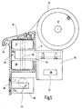
Zu der Markise 11 gehört ein Markisentuch 15, dessen gebäudenahes Ende 16 an einer Wickelwelle 17 befestigt ist. Das andere Ende 18 ist an einer Fallschiene 19 z.B. in einer entsprechenden Kedernut gefasst. Die Fallschiene 19 ist vorzugsweise horizontal und parallel zu der Wickelwelle 17 angeordnet.To the
Die Fallschiene 19 wird von zum Beispiel aus
Das von der Gebäudewand 10 fern liegende Ende des Markisenarms 20, 21 trägt eine Rollenanordnung 26, 27, die in
Die Fallschiene 19 ist als Führungsprofil ausgebildet. Dazu weist sie beispielsweise einen sich längs durch die Fallschiene 19 erstreckenden Innenraum 32 auf, der, wie dargestellt, rechteckig oder auch anderweitig geformt sein kann. Er ist an seiner Gebäudewand 10 zugewandten Seite durch einen Schlitz 33 zugänglich, durch den sich die Lasche 31 hindurch erstreckt. Die Rollenanordnung 26 ist vorzugsweise in dem Innenraum 32 angeordnet und kann längs der Fallschiene 19 laufen. Die vertikalen Begrenzungswände des Innenraums 32 bilden Laufbahnen für die Rollen 27, 28.The
Die Lasche 31 ist vorzugsweise Teil eines Formstücks 34 z.B. aus Metall, das an das freie Ende des Markisenarms 20 (oder 21) angesetzt ist. Das Formstück 34 ist gesondert in
Während das Formstück 34 zur Lagerung des zusätzlichen Sonnenschutzes 12 an dem Markisenarm 20 oder 21 dient, kann an der Fallschiene 19 ein sich nach unten erstreckender Fortsatz 38 vorgesehen sein, der ebenfalls der Lagerung eines zusätzlichen Sonnenschutzes (13,14 in
An der Fallschiene 19 können weitere Strukturen angeformt sein, beispielsweise eine Kedernut 41 zur Aufnahme des in
Der zusätzliche Sonnenschutz 12 stimmt vorzugsweise mit dem Sonnenschutz 13, 14 überein. Der einheitliche Sonnenschutz 12, 13, 14 kann wahlweise an der Fallschiene 19 oder den Markisenarmen 20, 21 angebracht werden. Die nachfolgende Beschreibung des Sonnenschutzes 12 gilt gleichermaßen für die anderen Sonnenschutze 13 und 14.The
Zu dem Sonnenschutz 12 gehört, wie aus den
Die Kassette 43 ist lediglich an ihren beiden Enden 45, 46 (
Während der Haken 47 in die Öffnung 36 des Formstücks 34 eingehakt ist, ist der Haken 48 mit einer höhenverstellbaren Aufhängung 49 verbunden. Zu dieser gehört vorzugsweise eine Aufnahmeöse 50, in die der Haken 48 greift, wobei die Aufhängeöse 50 von einem Zugmittel 51 getragen ist. Das Zugmittel 51 kann ein Seil, ein Draht oder ein Band, beispielsweise ein Kunststoffband oder vorzugsweise ein Stahlband sein. Diesem ist eine zum Beispiel an dem Markisenarm 20 oder 22 angeordnete Aufwickelvorrichtung 52 zugeordnet, Vorzugswiese ist diese mittel einer Sperrvorrichtung blockierbar. Sie weist eine Aufwickelspule 53 auf, die durch eine nicht weiter veranschaulichte Feder in Aufwickelrichtung vorgespannt ist. Ein Auslöseknopf 54 kann dazu vorgesehen sein, die Sperrvorrichtung freizugeben, um eine Drehung der Wickelspule 53 zu ermöglichen. Die Sperrvorrichtung kann durch einen Schieber gebildet sein, der auf die Wickelspule 53 einwirkt, um diese zu arretieren. Der Auslöseknopf 54 kann von Hand betätigbar sein. Vorzugsweise ist das auf die Wickelspule 53 wirkende Aufwickelmoment so groß, dass die Zugkraft an dem Zugmittel 51 das Gewicht des Sonnenschutzes 12 leicht überwindet.While the
Die insoweit beschriebene Markise 11 und der beschriebene Sonnenschutz 12 arbeiten wie folgt:
Die Markise 11 ist in der schematischen Darstellung nachFigur 5 in nicht ausgezogener Position dargestellt. Um sie auszufahren wird dieWickelwelle 17 so angetrieben, dassdas Markisentuch 15 abgewickelt wird. WieFigur 3 zeigt, schwenken dabei dieMarkisenarme von der Gebäudewand 10 weg. Dabeifahren die Rollenanordnungen der Fallschiene 19 voneinander weg,wobei die Fallschiene 19durch das Markisentuch 15 und dieMarkisenarme den Markisenarmen Figur 3 dargestellt, schlussendlich (fast) einen rechten Winkel erreicht. Vorzugsweise sind dieRollenanordnungen Stege 31, diedie Rollenanordnungen Markisenarme der Fallschiene 19 anstoßen.
- The
awning 11 is shown in the schematic representationFIG. 5 shown in undressed position. To extend it, the windingshaft 17 is driven so that theawning fabric 15 is unwound. AsFIG. 3 shows, while pivoting theawning arms respective spring 55 of thebuilding wall 10 away. Theroller assemblies drop rail 19, thedrop rail 19 being held parallel to thebuilding wall 10 by theawning cloth 15 and theawning arms awning arms building wall 10 acute angle increases increasingly, until he, as inFIG. 3 shown, finally reached (almost) a right angle. Preferably, theroller assemblies awning arms webs 31 which carry theroller assemblies awning arms drop rail 19.
Bei dem Ausfahren der Markise nimmt die von den Markisenarmen 20, 21 auf die Fallschiene 19 ausgeübte von der Gebäudewand 10 weg wirkende Kraft trotz abnehmender Federkraft infolge der Winkeländerung des Winkels zwischen den Markisenarmen und der Fallschiene zu oder bleibt zumindest konstant.During the extension of the awning, the force exerted by the
Wenn die Markisenarme 20, 21 von der Gebäudewand 10 weg gestreckt sind, ist die Markise 1 ausgefahren. Dieser Zustand ist in den
Die Markise kann bedarfsweise jederzeit eingefahren werden. Befindet sich der seitliche Sonnenschutz 12 noch in Auszugsposition, hindert er das Einziehen der Markise nicht. Damit kann beispielsweise eine motorbetätigte Markise jederzeit automatisch eingefahren werden, ohne dass dadurch Beschädigungen oder Gefahren entstehen.If necessary, the awning can be retracted at any time. If the
Andererseits ist es durch die Aufwickelvorrichtung 52 möglich, eine besonders sichere Verstauposition zu finden. Zunächst wird der Behang, beispielsweise das Rollo, auf die Wickelwelle 44 aufgewickelt. Das Sonnenschutzmittel des Sonnenschutzes 12 ist somit möglichst vollständig von der Kassette 43 aufgenommen. Zum weiteren Einfahren wird der Auslöseknopf 54 betätigt. Damit wird die Wickelspule 53 freigegeben und das rechte Ende 46 der Kassette 43 nach oben gezogen, bis diese an dem Markisenarm 20 oder 22 anliegt. Es kann die Markise 10 nun durch Aufwickeln des Markisentuchs 15 wie vorstehend beschrieben eingefahren werden.On the other hand, it is possible by the winding
Es ist auch möglich, erst die Markise 11 einzufahren und dann den Sonnenschutz 12 durch Betätigung der Sperre 54 in seine obere Position zu verstellen. Ersichtlicherweise sind somit eine Markise 11 sowie ein Sonnenschutz 12 geschaffen, bei denen Fehlbedienungen weitgehend ausgeschlossen sind. Der Aufbau ist nicht nur konstruktiv, sondern auch hinsichtlich seiner Bedienung robust.It is also possible to retract only the
Die erfindungsgemäße Markise weist zwei Markisenarme auf, die an der Fallschiene in Linearführungen gehalten sind. Zusätzlich ist ein Sonnenschutz 12, 13, 14 vorgesehen, dessen Kassettengehäuse nur an seinen beiden Enden 45, 46 durch geeignete Befestigungsmittel gehalten ist. Vorzugsweise ist zumindest eines der beiden Enden um eine Horizontalachse (Steg 37) schwenkbar gehalten, während das andere Ende 46 durch eine höhenverstellbare Aufhängung 49 nach oben oder unten verstellt werden kann.The awning according to the invention has two awning arms, which are held on the drop rail in linear guides. In addition, a
Die Bedienung ist besonders einfach und sicher.The operation is very easy and safe.
- 1010
- Gebäudewandbuilding wall
- 1111
- Markiseawning
- 12 - 1412 - 14
- Zusätzlicher SonnenschutzAdditional sunscreen
- 1515
- Markisentuchawning fabric
- 1616
-
Erstes Ende des Markisentuchs 15First end of the
awning 15 - 1717
- Wickelwellewinding shaft
- 1818
-
Zweites Ende des Markisentuchs 15Second end of the
awning 15 - 1919
- Fallschienedrop rail
- 2020
- Erster MarkisenarmFirst awning arm
- 2121
- Zweiter MarkisenarmSecond awning arm
- 22, 2322, 23
- Lagerungstorage
- 2424
- Schwenkachseswivel axis
- 2525
- Markisenkastenawning case
- 26, 2726, 27
- Rollenanordnungroller assembly
- 2828
-
Obere Rolle der Rollenanordnung 26Upper role of the
roller assembly 26 - 2929
-
Untere Rolle der Rollenanordnung 26Lower roll of the
roller assembly 26 - 3030
-
Achse der Rollen 27, 28Axis of the
rollers - 3131
- Lascheflap
- 3232
- Innenrauminner space
- 3333
- Schlitzslot
- 3434
- Formstückfitting
- 3535
- Fortsatzextension
- 3636
- Öffnungopening
- 3737
- Stegweb
- 3838
- Fortsatzextension
- 3939
- Bügelhanger
- 4040
- Durchgangpassage
- 4141
- Kedernutpiping groove
- 4242
- Volantflounce
- 4343
- Kassettecassette
- 4444
- Wickelwellewinding shaft
- 4545
- Linkes EndeLeft end
- 4646
- Rechtes EndeRight end
- 4747
- Linker HakenLeft hook
- 4848
- Rechter HakenRight hook
- 4949
- Höhenverstellbare AufhängungHeight adjustable suspension
- 5050
- Aufhängeösehanging loop
- 5151
- Zugmitteltraction means
- 5252
- Aufwickelvorrichtungrewinder
- 5353
- Aufwickelspuleup reel
- 5454
- Auslöseknopfrelease button
- 5555
- Federfeather
- 5656
- Endstücktail
- 5757
- Abschattungsvorrichtung 58Shading device 58
- 5959
- 6060
Claims (10)
mit zwei Markisenarmen (20, 21), die gebäudeseitig an Gelenken (22, 23) um vertikale Achsen (24) schwenkbar gelagert sind,
mit einer Wickelwelle (17), an der eine erste Kante (16) eines Markisentuchs (15) befestigt ist,
mit einer Fallschiene (19), an der eine zweite, der ersten Kante (16) gegenüberliegende Kante (18) des Markisentuchs (15) befestigt ist,
wobei die Fallschiene (19) ein in ihrer Längsrichtung verlaufendes Führungsprofil aufweist, an dem die Arme (20, 21) längs der Fallschiene (19) beweglich gelagert sind.Awning (10) with additional sun protection
with two awning arms (20, 21), which are pivotally mounted on joints (22, 23) about vertical axes (24) on the building side,
with a winding shaft (17) to which a first edge (16) of an awning cloth (15) is attached,
with a drop rail (19) to which a second edge (18) of the awning cloth (15) opposite the first edge (16) is fastened,
wherein the drop rail (19) has a guide profile extending in its longitudinal direction, on which the arms (20, 21) are movably mounted along the drop rail (19).
wobei das Kassettengehäuse (43) an seinen beiden Enden (45, 46) Befestigungsvorrichtungen (46, 47) zur Anbringung des Kassettengehäuses (43) an einer Markise (11) aufweist.Sun protection (12) for an awning (11) with a cassette housing (12) in which a shading device (57) is arranged,
wherein the cassette housing (43) at its two ends (45, 46) fastening means (46, 47) for attachment of the cassette housing (43) on an awning (11).
Applications Claiming Priority (1)
| Application Number | Priority Date | Filing Date | Title |
|---|---|---|---|
| DE102011000653A DE102011000653A1 (en) | 2011-02-11 | 2011-02-11 | Sun protection system |
Publications (1)
| Publication Number | Publication Date |
|---|---|
| EP2500489A2 true EP2500489A2 (en) | 2012-09-19 |
Family
ID=45560813
Family Applications (1)
| Application Number | Title | Priority Date | Filing Date |
|---|---|---|---|
| EP12154230A Withdrawn EP2500489A2 (en) | 2011-02-11 | 2012-02-07 | Sun protection system |
Country Status (2)
| Country | Link |
|---|---|
| EP (1) | EP2500489A2 (en) |
| DE (1) | DE102011000653A1 (en) |
Citations (5)
| Publication number | Priority date | Publication date | Assignee | Title |
|---|---|---|---|---|
| DE1896000U (en) | 1961-06-19 | 1964-07-02 | Marcel Andre Belin | SUN CURTAIN. |
| DE3315504A1 (en) | 1983-04-28 | 1985-04-18 | Bernhard Dipl.-Ing. 8434 Berching Benkendorff | Pivoting frame for an awning - drive and side curtain - |
| DE3744590C1 (en) | 1987-12-31 | 1989-09-14 | Clauss Markisen | Inclined awning with subsequent vertical area |
| DE20009461U1 (en) | 2000-05-25 | 2000-11-02 | Gerhardt Roland | Motorized anti-glare curtain |
| DE20209746U1 (en) | 2002-06-24 | 2002-09-26 | Behr Karl Guenter | Device for holding a side awning as privacy and sun protection |
Family Cites Families (2)
| Publication number | Priority date | Publication date | Assignee | Title |
|---|---|---|---|---|
| DE189600C (en) | ||||
| DE8430086U1 (en) | 1984-10-12 | 1985-01-31 | Möbius, Wolf, 2070 Ahrensburg | AWNING |
-
2011
- 2011-02-11 DE DE102011000653A patent/DE102011000653A1/en not_active Withdrawn
-
2012
- 2012-02-07 EP EP12154230A patent/EP2500489A2/en not_active Withdrawn
Patent Citations (5)
| Publication number | Priority date | Publication date | Assignee | Title |
|---|---|---|---|---|
| DE1896000U (en) | 1961-06-19 | 1964-07-02 | Marcel Andre Belin | SUN CURTAIN. |
| DE3315504A1 (en) | 1983-04-28 | 1985-04-18 | Bernhard Dipl.-Ing. 8434 Berching Benkendorff | Pivoting frame for an awning - drive and side curtain - |
| DE3744590C1 (en) | 1987-12-31 | 1989-09-14 | Clauss Markisen | Inclined awning with subsequent vertical area |
| DE20009461U1 (en) | 2000-05-25 | 2000-11-02 | Gerhardt Roland | Motorized anti-glare curtain |
| DE20209746U1 (en) | 2002-06-24 | 2002-09-26 | Behr Karl Guenter | Device for holding a side awning as privacy and sun protection |
Also Published As
| Publication number | Publication date |
|---|---|
| DE102011000653A1 (en) | 2012-08-16 |
Similar Documents
| Publication | Publication Date | Title |
|---|---|---|
| EP0322534B1 (en) | Inclined awning | |
| EP1936105B1 (en) | Vertical shading | |
| EP0119550B1 (en) | Collapsible tent roof, in particular an awning, tent canopy for dormobiles and the like | |
| DE4021264C2 (en) | Inclined awning | |
| EP2535501B1 (en) | Building shadowing device with extendable guide rails | |
| EP3054063B2 (en) | Awning with lowerable guide rails | |
| DE202007017061U1 (en) | Universal frame for curtains or roller blinds | |
| DE3607944C2 (en) | ||
| EP2500489A2 (en) | Sun protection system | |
| DE19621956B4 (en) | Awning with inevitably moved valance | |
| DE202006021144U1 (en) | vertical awnings | |
| DE202009009925U1 (en) | Articulated arm awning with additional sun protection | |
| DE19814577C1 (en) | Sun-shade arrangement with length of canvas unrolled from shaft | |
| DE102010017729A1 (en) | Vertical blind and sun guard for awning in e.g. balcony, of building, has connecting unit connecting support rail with arm of awning, where connecting unit defines adjustable spacing between arm of awning and support rail | |
| AT11824U1 (en) | VERTICAL AND HORIZONTAL CONTAINABLE ROLLOSYSTEM, ESPECIALLY INSECT SCREENS ROLLOSYSTEM, WITH LOW BUILDING DEPTH | |
| DE2549935A1 (en) | Swivelling roof window awning cover - has housing at top spaced above window, permitting air flow | |
| CH650305A5 (en) | AWNING. | |
| EP3027835B1 (en) | Motor-driven shading system | |
| DE2527382C3 (en) | Protective cover for pivoting roof windows | |
| DE3246353A1 (en) | Sunshade arrangement | |
| DE4141543C1 (en) | External roller shutter for windows and doors - has winder in housing with handle, by which pull belt can be pulled through aperture in frame or wall | |
| DE202007009717U1 (en) | Arrangement with a shading device for a translucent surface element | |
| EP1780350B1 (en) | Awning with positive return | |
| DE102022103533A1 (en) | shading device | |
| DE4037264A1 (en) | Scan protection for triangular window - comprises inclined upper rail, pivotable lower rail, and intermediate folded sheet |
Legal Events
| Date | Code | Title | Description |
|---|---|---|---|
| PUAI | Public reference made under article 153(3) epc to a published international application that has entered the european phase |
Free format text: ORIGINAL CODE: 0009012 |
|
| AK | Designated contracting states |
Kind code of ref document: A2 Designated state(s): AL AT BE BG CH CY CZ DE DK EE ES FI FR GB GR HR HU IE IS IT LI LT LU LV MC MK MT NL NO PL PT RO RS SE SI SK SM TR |
|
| AX | Request for extension of the european patent |
Extension state: BA ME |
|
| STAA | Information on the status of an ep patent application or granted ep patent |
Free format text: STATUS: THE APPLICATION IS DEEMED TO BE WITHDRAWN |
|
| 18D | Application deemed to be withdrawn |
Effective date: 20160901 |