EP2499302B1 - Machine for processing a track - Google Patents
Machine for processing a track Download PDFInfo
- Publication number
- EP2499302B1 EP2499302B1 EP10759581.1A EP10759581A EP2499302B1 EP 2499302 B1 EP2499302 B1 EP 2499302B1 EP 10759581 A EP10759581 A EP 10759581A EP 2499302 B1 EP2499302 B1 EP 2499302B1
- Authority
- EP
- European Patent Office
- Prior art keywords
- sweeping
- machine
- track
- machine according
- hand
- Prior art date
- Legal status (The legal status is an assumption and is not a legal conclusion. Google has not performed a legal analysis and makes no representation as to the accuracy of the status listed.)
- Active
Links
- 238000010408 sweeping Methods 0.000 claims description 62
- 239000002023 wood Substances 0.000 claims 1
- 241001417527 Pempheridae Species 0.000 description 4
- 230000001419 dependent effect Effects 0.000 description 1
- 238000007634 remodeling Methods 0.000 description 1
Images

Classifications
-
- E—FIXED CONSTRUCTIONS
- E01—CONSTRUCTION OF ROADS, RAILWAYS, OR BRIDGES
- E01B—PERMANENT WAY; PERMANENT-WAY TOOLS; MACHINES FOR MAKING RAILWAYS OF ALL KINDS
- E01B27/00—Placing, renewing, working, cleaning, or taking-up the ballast, with or without concurrent work on the track; Devices therefor; Packing sleepers
- E01B27/02—Placing the ballast; Making ballastway; Redistributing ballasting material; Machines or devices therefor; Levelling means
- E01B27/023—Spreading, levelling or redistributing ballast already placed
- E01B27/026—Spreading, levelling or redistributing ballast already placed by means of driven tools, e.g. rotating brooms or digging devices
Definitions
- the invention relates to a machine for processing a track according to the preamble of claim 1.
- a device for distributing and profiling the bed ballast of a track is known.
- This track-traveling machine has flank and middle plows.
- a sweeping device is arranged which has two sweeping brushes. The captured by these, excess ballast is transported via a conveyor in a ballast silo, from where it can be re-introduced into the track when needed.
- the object of the present invention is now to provide a machine of the type mentioned, the sweeping device can be adapted quickly to changing track conditions.
- the brushes can be optimally adapted in a very short time to different types of superstructures or different types of sleep while avoiding longer changeover times and remodeling.
- wooden sleepers are often encountered in the switch area, while concrete sleepers predominate on the open road.
- sweeping brushes that are most suitable for these types of sleepers, the entire track can be machined with minimal disruption to the working drive.
- Fig. 1 a simplified side view of a machine for sweeping a track
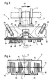
- Fig. 2 and 3 enlarged illustrations of sweeping devices
- Fig. 4 a schematic view in the direction of another sweeping device.
- An in Fig. 1 illustrated machine 1 for processing a track 2 consists essentially of a supported on rail chassis 3 Machine frame 4. At this height adjustable by drives 5 sweeping device 6, a car 7 and various ballast plows 8 are arranged. A motor 9 serves to supply all the drives still to be described.
- the sweeping device 6 has two sweeping brushes 12, 13 rotatable in succession in a working direction 10 around horizontal, normal to the working direction 10 extending axes 11.
- the sweeping device 6 is formed pivotable about a vertical axis 14 relative to the machine frame 4.
- the sweeping brushes 12, 13 radially projecting from the axes 11, flexible sweeping elements 15 and are offset by drives 16 in rotation. Between the two sweeping brushes 12, 13 a horizontal and normal to the working direction 10 extending cross conveyor belt 17 is arranged.
- the sweeping elements 15 of the first sweeping brush 12 are designed for processing wooden sleepers 18 and the sweeping elements 15 of the second sweeping brush 13 for processing concrete sleepers 19.
- the drives 5 for height adjustment of the sweeping device 6 and articulation rods 20 are articulated on the one hand to the sweeping device 6 and on the other hand to a pivoting device 21. This is connected by a drive 22 pivotally connected to the machine frame 4.
- the drives 5 are hinged on the one hand to the pivoting device 21 connected to the sweeping device 6 and on the other hand on the machine frame 4.
- sweeping brushes 12, 13 for processing concrete sleepers 19 and so-called two-block sleepers 23 can be installed in the sweeping device 6.
- the sweeping elements 15 therefore have different lengths l 1 , l 2 .
- the operation of the sweeping device 6 will be briefly described below. This is first pivoted by applying the drive 22 about the axis 14 so that the used for sweeping brush 12 and 13 is in a rearward position with respect to the working direction 10. Thereafter, the sweeping device 6 is lowered by operating the drives 5 on the track 2 on which it is supported by means of flange wheels 24. An exact height adjustment or lowering of the intended for use rear sweeping brush 13 is done with the help of other, attached to the sweeping device 6, 25 drives with these readjusting the sweeping brushes 12, 13 in the increasing wear of the sweeping elements 15 is possible.
Landscapes
- Engineering & Computer Science (AREA)
- Architecture (AREA)
- Civil Engineering (AREA)
- Structural Engineering (AREA)
- Machines For Laying And Maintaining Railways (AREA)
Description
Die Erfindung betrifft eine Maschine zur Bearbeitung eines Gleises gemäß dem Oberbegriff von Anspruch 1.The invention relates to a machine for processing a track according to the preamble of claim 1.
Aus
Durch die japanische Gebrauchsmuster-Veröffentlichung 5001/81 ist auch eine Kehrmaschine bekannt, bei der zwischen zwei Schienenfahrwerken eine zwei Kehrbürsten aufweisende Kehrvorrichtung höhenverstellbar an einem Maschinenrahmen befestigt ist.By Japanese Utility Model Publication 5001/81 also a sweeper is known in which a sweeping device comprising two sweeping brushes is height-adjustable attached to a machine frame between two rail carriages.
Schließlich ist aus
Die Aufgabe der vorliegenden Erfindung liegt nun in der Schaffung einer Maschine der eingangs genannten Art, deren Kehrvorrichtung rasch an wechselnde Gleisverhältnisse angepasst werden kann.The object of the present invention is now to provide a machine of the type mentioned, the sweeping device can be adapted quickly to changing track conditions.
Diese Aufgabe wird erfindungsgemäß mit einer Maschine der gattungsgemäßen Art dadurch gelöst, dass die Kehrvorrichtung um eine vertikale Achse um 180° relativ zum Maschinenrahmen verschwenkbar ausgebildet ist.This object is achieved with a machine of the generic type, characterized in that the sweeping device is designed to pivot about a vertical axis by 180 ° relative to the machine frame.
Mit einer derartig ausgebildeten Kehrvorrichtung können die Kehrbürsten unter Vermeidung längerer Umrüstzeiten und Umbauarbeiten optimal und in kürzester Zeit an verschiedene Oberbauarten bzw. verschiedene Schwellenarten angepasst werden. Beispielsweise sind im Weichenbereich oft Holzschwellen anzutreffen, während auf freier Strecke Betonschwellen überwiegen. Durch Ausrüsten der Kehrvorrichtung mit für diese Arten von Schwellen besonders geeigneten Kehrbürsten kann das gesamte Gleis mit nur minimaler Unterbrechung der Arbeitsfahrt bearbeitet werden.With such a trained sweeping the brushes can be optimally adapted in a very short time to different types of superstructures or different types of sleep while avoiding longer changeover times and remodeling. For example, wooden sleepers are often encountered in the switch area, while concrete sleepers predominate on the open road. By equipping the sweeper with sweeping brushes that are most suitable for these types of sleepers, the entire track can be machined with minimal disruption to the working drive.
Weitere Vorteile der Erfindung ergeben sich aus den Unteransprüchen und der Zeichnungsbeschreibung.Further advantages of the invention will become apparent from the dependent claims and the drawing description.
Im Folgenden wird die Erfindung anhand in der Zeichnung dargestellter Ausführungsbeispiele näher beschrieben. Es zeigen:In the following the invention will be described with reference to embodiments illustrated in the drawings. Show it:
Eine in
Wie in
Bei der in
Wie in
Im Folgenden wird der Arbeitseinsatz der Kehrvorrichtung 6 kurz beschrieben. Diese wird zunächst durch Beaufschlagen des Antriebes 22 um die Achse 14 so verschwenkt, dass sich die zum Einsatz kommende Kehrbürste 12 bzw. 13 in einer betreffend die Arbeitsrichtung 10 hinteren Position befindet. Danach wird die Kehrvorrichtung 6 durch Betätigen der Antriebe 5 auf das Gleis 2 abgesenkt, auf dem sie sich mittels Spurkranzrollen 24 abstützt. Eine exakte höhenmäßige Anpassung bzw. Absenkung der für den Einsatz vorgesehenen hinteren Kehrbürste 13 erfolgt mit Hilfe weiterer, an der Kehrvorrichtung 6 angebrachter, Antriebe 25. Mit diesen ist auch ein Nachjustieren der Kehrbürsten 12, 13 bei der zunehmenden Abnützung der Kehrelemente 15 möglich.The operation of the
Wie in
Es ist auch denkbar, dass zwei bauartgleiche Kehrbürsten 12, 13 in die Kehrvorrichtung 6 eingebaut werden. Nach Abnutzung der ersten Kehrbürste 12 wird die Kehrvorrichtung 6 verschwenkt und die zweite Kehrbürste 13 kommt zum Einsatz. Damit können besonders lange Gleisstücke mit einem Schwellentyp bearbeitet werden, ohne dass die abgenutzte erste Kehrbürste 12 mit größerem Zeitaufwand ausgewechselt werden muss.It is also conceivable that two design-identical
Claims (6)
- A machine (1) for treating a track (2), including a machine frame (4) supported on on-track undercarriages (3) and, arranged on the same, a sweeping device (6) vertically adjustable by drives (5), the sweeping device comprising two sweeping brushes (12, 13), arranged one following the other in a working direction (10) and rotatable about horizontal axes (11) extending perpendicularly to the working direction (10) and having radially projecting, flexible sweeping elements (15), and a transverse conveyor belt (17), characterized in that the sweeping device (6) is designed to be able to swivel by 180° about a vertical axis (14) relative to the machine frame (4).
- A machine according to claim 1, characterized in that the transverse conveyor belt (17) extending horizontally and perpendicularly to the working direction (10) is arranged between the two sweeping brushes (12, 13).
- A machine according to claim 1 or 2, characterized in that the sweeping elements (15) of the first sweeping brush (12) are designed for the treatment of wood sleepers (18), and the sweeping elements (15) of the second sweeping brush (13) are designed for the treatment of concrete sleepers (19).
- A machine according to claim 1, 2 or 3, characterized in that the sweeping elements (15) have different lengths (l1, l2) for the treatment of different sleepers (18, 19, 23).
- A machine according to one of claims 1 to 4, characterized in that the drives (5) for vertical adjustment of the sweeping device (6) are articulatedly connected, on the one hand, to the sweeping device (6) and, on the other hand, to a swivelling device (21) connected to the machine frame (4).
- A machine according to one of claims 1 to 4, characterized in that the drives (5) for vertical adjustment of the sweeping device (6) are articulatedly connected, on the one hand, to a swivelling device (21) connected to the same, and, on the other hand, to the machine frame (4).
Priority Applications (1)
| Application Number | Priority Date | Filing Date | Title |
|---|---|---|---|
| PL10759581T PL2499302T3 (en) | 2009-11-11 | 2010-09-18 | Machine for processing a track |
Applications Claiming Priority (2)
| Application Number | Priority Date | Filing Date | Title |
|---|---|---|---|
| AT0178409A AT508151B1 (en) | 2009-11-11 | 2009-11-11 | MACHINE FOR MACHINING A JOURNEY |
| PCT/EP2010/005738 WO2011057689A1 (en) | 2009-11-11 | 2010-09-18 | Machine for processing a track |
Publications (2)
| Publication Number | Publication Date |
|---|---|
| EP2499302A1 EP2499302A1 (en) | 2012-09-19 |
| EP2499302B1 true EP2499302B1 (en) | 2013-08-28 |
Family
ID=42941388
Family Applications (1)
| Application Number | Title | Priority Date | Filing Date |
|---|---|---|---|
| EP10759581.1A Active EP2499302B1 (en) | 2009-11-11 | 2010-09-18 | Machine for processing a track |
Country Status (6)
| Country | Link |
|---|---|
| EP (1) | EP2499302B1 (en) |
| AT (1) | AT508151B1 (en) |
| DK (1) | DK2499302T3 (en) |
| ES (1) | ES2436448T3 (en) |
| PL (1) | PL2499302T3 (en) |
| WO (1) | WO2011057689A1 (en) |
Families Citing this family (1)
| Publication number | Priority date | Publication date | Assignee | Title |
|---|---|---|---|---|
| AT522721B1 (en) * | 2019-06-26 | 2020-12-15 | Stmg Gmbh | Track ballast leveling device |
Family Cites Families (5)
| Publication number | Priority date | Publication date | Assignee | Title |
|---|---|---|---|---|
| DE1952715B1 (en) * | 1969-10-20 | 1971-05-06 | Windhoff Rheiner Maschf | Machine movable on the track for ballasting the track |
| AT322606B (en) | 1971-05-24 | 1975-05-26 | Plasser Bahnbaumasch Franz | MOBILE DEVICE FOR DISTRIBUTING AND PROFILING THE BED BALL OF A RAILWAY TRACK |
| JPS6011123Y2 (en) | 1979-06-19 | 1985-04-13 | 芝浦メカトロニクス株式会社 | Double rotary brush device for ballast sweeper |
| DE59405685D1 (en) * | 1993-07-08 | 1998-05-20 | Plasser Bahnbaumasch Franz | Sweeper for sweeping a track |
| EP0743399A1 (en) * | 1995-05-16 | 1996-11-20 | Speno International S.A. | Track cleaning apparatus |
-
2009
- 2009-11-11 AT AT0178409A patent/AT508151B1/en not_active IP Right Cessation
-
2010
- 2010-09-18 ES ES10759581.1T patent/ES2436448T3/en active Active
- 2010-09-18 WO PCT/EP2010/005738 patent/WO2011057689A1/en active Application Filing
- 2010-09-18 EP EP10759581.1A patent/EP2499302B1/en active Active
- 2010-09-18 DK DK10759581.1T patent/DK2499302T3/en active
- 2010-09-18 PL PL10759581T patent/PL2499302T3/en unknown
Also Published As
| Publication number | Publication date |
|---|---|
| WO2011057689A1 (en) | 2011-05-19 |
| AT508151A4 (en) | 2010-11-15 |
| EP2499302A1 (en) | 2012-09-19 |
| PL2499302T3 (en) | 2014-01-31 |
| AT508151B1 (en) | 2010-11-15 |
| ES2436448T3 (en) | 2014-01-02 |
| DK2499302T3 (en) | 2013-12-09 |
Similar Documents
| Publication | Publication Date | Title |
|---|---|---|
| WO1995030797A1 (en) | Transport vehicle for track sections | |
| EP0633355B1 (en) | Track sweeping machine | |
| DD283175A5 (en) | RUNNING MACHINE WITH PLANNING PLOW FOR DISTRIBUTING AND PROFILING THE BED SCATTER | |
| AT402952B (en) | TRACK CONSTRUCTION MACHINE FOR CONTROLLED LOWERING OF A TRACK | |
| EP1607523B1 (en) | A machine for exchanging damaged ties of a railroad track. | |
| AT506585B1 (en) | tamping machine | |
| DE3819717A1 (en) | CONTINUOUSLY (NON-STOP) TRAVELABLE TRACKING MACHINE | |
| EP1179635B1 (en) | Apparatus for removing an existing railway track and laying a new track | |
| EP1251205A2 (en) | Device for removing the ballast from a trailway track | |
| DE20002815U1 (en) | Device for grinding rails | |
| EP0416135B1 (en) | Track-mobile machine for distributing and profiling the bedding ballast of a railway track | |
| EP0784121B1 (en) | Tamping device for railway track | |
| DE3908007C2 (en) | Track construction machine with track stabilizer | |
| DE102007060215A1 (en) | Device for processing a running edge | |
| EP2775035B1 (en) | Sweeping device | |
| EP0887464B1 (en) | Machine for compacting and profiling the railway ballast | |
| DE202006015507U1 (en) | Machine for grinding railway track has a frame supported on four flanged wheels and with a tilt controlled grinding system | |
| CH685059A5 (en) | Mobile Tamping machine with transversely and vertically adjustable tamping units. | |
| EP2499302B1 (en) | Machine for processing a track | |
| EP0665331B1 (en) | Ballast tamping machine for railways | |
| DE4104876C2 (en) | Mobile track construction machine for processing the ballast bedding of a track | |
| EP2438238A1 (en) | Ballast plow for ballasting a track | |
| AT510158B1 (en) | METHOD AND MACHINE FOR CLEANING A SCHOTTERBETTUNG OF A TRAIL | |
| EP0787858B1 (en) | Machine for carrying out railway trackworks | |
| EP3063332B1 (en) | Tamping machine comprising a rotatable mounted subframe |
Legal Events
| Date | Code | Title | Description |
|---|---|---|---|
| PUAI | Public reference made under article 153(3) epc to a published international application that has entered the european phase |
Free format text: ORIGINAL CODE: 0009012 |
|
| 17P | Request for examination filed |
Effective date: 20120611 |
|
| AK | Designated contracting states |
Kind code of ref document: A1 Designated state(s): AL AT BE BG CH CY CZ DE DK EE ES FI FR GB GR HR HU IE IS IT LI LT LU LV MC MK MT NL NO PL PT RO SE SI SK SM TR |
|
| RIN1 | Information on inventor provided before grant (corrected) |
Inventor name: FELBER, HANNES |
|
| DAX | Request for extension of the european patent (deleted) | ||
| GRAP | Despatch of communication of intention to grant a patent |
Free format text: ORIGINAL CODE: EPIDOSNIGR1 |
|
| INTG | Intention to grant announced |
Effective date: 20130409 |
|
| GRAS | Grant fee paid |
Free format text: ORIGINAL CODE: EPIDOSNIGR3 |
|
| GRAA | (expected) grant |
Free format text: ORIGINAL CODE: 0009210 |
|
| AK | Designated contracting states |
Kind code of ref document: B1 Designated state(s): AL AT BE BG CH CY CZ DE DK EE ES FI FR GB GR HR HU IE IS IT LI LT LU LV MC MK MT NL NO PL PT RO SE SI SK SM TR |
|
| REG | Reference to a national code |
Ref country code: GB Ref legal event code: FG4D Free format text: NOT ENGLISH |
|
| REG | Reference to a national code |
Ref country code: CH Ref legal event code: EP |
|
| REG | Reference to a national code |
Ref country code: AT Ref legal event code: REF Ref document number: 629449 Country of ref document: AT Kind code of ref document: T Effective date: 20130915 |
|
| REG | Reference to a national code |
Ref country code: IE Ref legal event code: FG4D Free format text: LANGUAGE OF EP DOCUMENT: GERMAN |
|
| REG | Reference to a national code |
Ref country code: DE Ref legal event code: R096 Ref document number: 502010004537 Country of ref document: DE Effective date: 20131024 |
|
| REG | Reference to a national code |
Ref country code: DK Ref legal event code: T3 Effective date: 20131202 |
|
| REG | Reference to a national code |
Ref country code: SE Ref legal event code: TRGR |
|
| REG | Reference to a national code |
Ref country code: NL Ref legal event code: T3 |
|
| REG | Reference to a national code |
Ref country code: ES Ref legal event code: FG2A Ref document number: 2436448 Country of ref document: ES Kind code of ref document: T3 Effective date: 20140102 |
|
| REG | Reference to a national code |
Ref country code: LT Ref legal event code: MG4D |
|
| PG25 | Lapsed in a contracting state [announced via postgrant information from national office to epo] |
Ref country code: LT Free format text: LAPSE BECAUSE OF FAILURE TO SUBMIT A TRANSLATION OF THE DESCRIPTION OR TO PAY THE FEE WITHIN THE PRESCRIBED TIME-LIMIT Effective date: 20130828 Ref country code: NO Free format text: LAPSE BECAUSE OF FAILURE TO SUBMIT A TRANSLATION OF THE DESCRIPTION OR TO PAY THE FEE WITHIN THE PRESCRIBED TIME-LIMIT Effective date: 20131128 Ref country code: IS Free format text: LAPSE BECAUSE OF FAILURE TO SUBMIT A TRANSLATION OF THE DESCRIPTION OR TO PAY THE FEE WITHIN THE PRESCRIBED TIME-LIMIT Effective date: 20131228 Ref country code: HR Free format text: LAPSE BECAUSE OF FAILURE TO SUBMIT A TRANSLATION OF THE DESCRIPTION OR TO PAY THE FEE WITHIN THE PRESCRIBED TIME-LIMIT Effective date: 20130828 Ref country code: CY Free format text: LAPSE BECAUSE OF FAILURE TO SUBMIT A TRANSLATION OF THE DESCRIPTION OR TO PAY THE FEE WITHIN THE PRESCRIBED TIME-LIMIT Effective date: 20130911 Ref country code: PT Free format text: LAPSE BECAUSE OF FAILURE TO SUBMIT A TRANSLATION OF THE DESCRIPTION OR TO PAY THE FEE WITHIN THE PRESCRIBED TIME-LIMIT Effective date: 20131230 |
|
| REG | Reference to a national code |
Ref country code: PL Ref legal event code: T3 |
|
| PG25 | Lapsed in a contracting state [announced via postgrant information from national office to epo] |
Ref country code: LV Free format text: LAPSE BECAUSE OF FAILURE TO SUBMIT A TRANSLATION OF THE DESCRIPTION OR TO PAY THE FEE WITHIN THE PRESCRIBED TIME-LIMIT Effective date: 20130828 Ref country code: FI Free format text: LAPSE BECAUSE OF FAILURE TO SUBMIT A TRANSLATION OF THE DESCRIPTION OR TO PAY THE FEE WITHIN THE PRESCRIBED TIME-LIMIT Effective date: 20130828 Ref country code: SI Free format text: LAPSE BECAUSE OF FAILURE TO SUBMIT A TRANSLATION OF THE DESCRIPTION OR TO PAY THE FEE WITHIN THE PRESCRIBED TIME-LIMIT Effective date: 20130828 Ref country code: GR Free format text: LAPSE BECAUSE OF FAILURE TO SUBMIT A TRANSLATION OF THE DESCRIPTION OR TO PAY THE FEE WITHIN THE PRESCRIBED TIME-LIMIT Effective date: 20131129 |
|
| PG25 | Lapsed in a contracting state [announced via postgrant information from national office to epo] |
Ref country code: CY Free format text: LAPSE BECAUSE OF FAILURE TO SUBMIT A TRANSLATION OF THE DESCRIPTION OR TO PAY THE FEE WITHIN THE PRESCRIBED TIME-LIMIT Effective date: 20130828 |
|
| PG25 | Lapsed in a contracting state [announced via postgrant information from national office to epo] |
Ref country code: EE Free format text: LAPSE BECAUSE OF FAILURE TO SUBMIT A TRANSLATION OF THE DESCRIPTION OR TO PAY THE FEE WITHIN THE PRESCRIBED TIME-LIMIT Effective date: 20130828 Ref country code: SK Free format text: LAPSE BECAUSE OF FAILURE TO SUBMIT A TRANSLATION OF THE DESCRIPTION OR TO PAY THE FEE WITHIN THE PRESCRIBED TIME-LIMIT Effective date: 20130828 Ref country code: RO Free format text: LAPSE BECAUSE OF FAILURE TO SUBMIT A TRANSLATION OF THE DESCRIPTION OR TO PAY THE FEE WITHIN THE PRESCRIBED TIME-LIMIT Effective date: 20130828 |
|
| PG25 | Lapsed in a contracting state [announced via postgrant information from national office to epo] |
Ref country code: MC Free format text: LAPSE BECAUSE OF FAILURE TO SUBMIT A TRANSLATION OF THE DESCRIPTION OR TO PAY THE FEE WITHIN THE PRESCRIBED TIME-LIMIT Effective date: 20130828 |
|
| REG | Reference to a national code |
Ref country code: DE Ref legal event code: R097 Ref document number: 502010004537 Country of ref document: DE |
|
| REG | Reference to a national code |
Ref country code: IE Ref legal event code: MM4A |
|
| PLBE | No opposition filed within time limit |
Free format text: ORIGINAL CODE: 0009261 |
|
| STAA | Information on the status of an ep patent application or granted ep patent |
Free format text: STATUS: NO OPPOSITION FILED WITHIN TIME LIMIT |
|
| PG25 | Lapsed in a contracting state [announced via postgrant information from national office to epo] |
Ref country code: IE Free format text: LAPSE BECAUSE OF NON-PAYMENT OF DUE FEES Effective date: 20130918 |
|
| 26N | No opposition filed |
Effective date: 20140530 |
|
| REG | Reference to a national code |
Ref country code: DE Ref legal event code: R097 Ref document number: 502010004537 Country of ref document: DE Effective date: 20140530 |
|
| REG | Reference to a national code |
Ref country code: DE Ref legal event code: R082 Ref document number: 502010004537 Country of ref document: DE Representative=s name: RAU, SCHNECK & HUEBNER PATENTANWAELTE RECHTSAN, DE |
|
| REG | Reference to a national code |
Ref country code: DE Ref legal event code: R081 Ref document number: 502010004537 Country of ref document: DE Owner name: PLASSER & THEURER, EXPORT VON BAHNBAUMASCHINEN, AT Free format text: FORMER OWNER: FRANZ PLASSER BAHNBAUMASCHINEN-INDUSTRIEGESELLSCHAFT M.B.H., WIEN, AT Effective date: 20141001 Ref country code: DE Ref legal event code: R082 Ref document number: 502010004537 Country of ref document: DE Representative=s name: RAU, SCHNECK & HUEBNER PATENTANWAELTE RECHTSAN, DE Effective date: 20141001 |
|
| PG25 | Lapsed in a contracting state [announced via postgrant information from national office to epo] |
Ref country code: SM Free format text: LAPSE BECAUSE OF FAILURE TO SUBMIT A TRANSLATION OF THE DESCRIPTION OR TO PAY THE FEE WITHIN THE PRESCRIBED TIME-LIMIT Effective date: 20130828 |
|
| PG25 | Lapsed in a contracting state [announced via postgrant information from national office to epo] |
Ref country code: MT Free format text: LAPSE BECAUSE OF FAILURE TO SUBMIT A TRANSLATION OF THE DESCRIPTION OR TO PAY THE FEE WITHIN THE PRESCRIBED TIME-LIMIT Effective date: 20130828 |
|
| PG25 | Lapsed in a contracting state [announced via postgrant information from national office to epo] |
Ref country code: BG Free format text: LAPSE BECAUSE OF FAILURE TO SUBMIT A TRANSLATION OF THE DESCRIPTION OR TO PAY THE FEE WITHIN THE PRESCRIBED TIME-LIMIT Effective date: 20130828 Ref country code: MK Free format text: LAPSE BECAUSE OF FAILURE TO SUBMIT A TRANSLATION OF THE DESCRIPTION OR TO PAY THE FEE WITHIN THE PRESCRIBED TIME-LIMIT Effective date: 20130828 Ref country code: HU Free format text: LAPSE BECAUSE OF FAILURE TO SUBMIT A TRANSLATION OF THE DESCRIPTION OR TO PAY THE FEE WITHIN THE PRESCRIBED TIME-LIMIT; INVALID AB INITIO Effective date: 20100918 Ref country code: LU Free format text: LAPSE BECAUSE OF NON-PAYMENT OF DUE FEES Effective date: 20130918 |
|
| REG | Reference to a national code |
Ref country code: FR Ref legal event code: PLFP Year of fee payment: 6 |
|
| REG | Reference to a national code |
Ref country code: FR Ref legal event code: PLFP Year of fee payment: 7 |
|
| REG | Reference to a national code |
Ref country code: FR Ref legal event code: PLFP Year of fee payment: 8 |
|
| REG | Reference to a national code |
Ref country code: FR Ref legal event code: PLFP Year of fee payment: 9 |
|
| PG25 | Lapsed in a contracting state [announced via postgrant information from national office to epo] |
Ref country code: AL Free format text: LAPSE BECAUSE OF FAILURE TO SUBMIT A TRANSLATION OF THE DESCRIPTION OR TO PAY THE FEE WITHIN THE PRESCRIBED TIME-LIMIT Effective date: 20130828 |
|
| PGFP | Annual fee paid to national office [announced via postgrant information from national office to epo] |
Ref country code: TR Payment date: 20230908 Year of fee payment: 14 Ref country code: NL Payment date: 20230918 Year of fee payment: 14 Ref country code: GB Payment date: 20230817 Year of fee payment: 14 Ref country code: CZ Payment date: 20230906 Year of fee payment: 14 Ref country code: AT Payment date: 20230828 Year of fee payment: 14 |
|
| PGFP | Annual fee paid to national office [announced via postgrant information from national office to epo] |
Ref country code: SE Payment date: 20230918 Year of fee payment: 14 Ref country code: PL Payment date: 20230906 Year of fee payment: 14 Ref country code: FR Payment date: 20230918 Year of fee payment: 14 Ref country code: DK Payment date: 20230918 Year of fee payment: 14 Ref country code: BE Payment date: 20230918 Year of fee payment: 14 |
|
| PGFP | Annual fee paid to national office [announced via postgrant information from national office to epo] |
Ref country code: ES Payment date: 20231004 Year of fee payment: 14 |
|
| PGFP | Annual fee paid to national office [announced via postgrant information from national office to epo] |
Ref country code: IT Payment date: 20230929 Year of fee payment: 14 Ref country code: DE Payment date: 20231124 Year of fee payment: 14 Ref country code: CH Payment date: 20231001 Year of fee payment: 14 |