EP0743399A1 - Track cleaning apparatus - Google Patents
Track cleaning apparatus Download PDFInfo
- Publication number
- EP0743399A1 EP0743399A1 EP96104266A EP96104266A EP0743399A1 EP 0743399 A1 EP0743399 A1 EP 0743399A1 EP 96104266 A EP96104266 A EP 96104266A EP 96104266 A EP96104266 A EP 96104266A EP 0743399 A1 EP0743399 A1 EP 0743399A1
- Authority
- EP
- European Patent Office
- Prior art keywords
- brushes
- equipment according
- rail
- brush
- box
- Prior art date
- Legal status (The legal status is an assumption and is not a legal conclusion. Google has not performed a legal analysis and makes no representation as to the accuracy of the status listed.)
- Withdrawn
Links
Images


Classifications
-
- E—FIXED CONSTRUCTIONS
- E01—CONSTRUCTION OF ROADS, RAILWAYS, OR BRIDGES
- E01H—STREET CLEANING; CLEANING OF PERMANENT WAYS; CLEANING BEACHES; DISPERSING OR PREVENTING FOG IN GENERAL CLEANING STREET OR RAILWAY FURNITURE OR TUNNEL WALLS
- E01H8/00—Removing undesirable matter from the permanent way of railways; Removing undesirable matter from tramway rails
Definitions
- the object of the present invention is to allow automatic cleaning, using a machine, of the railway, tramway or metro tracks, in and out of stations, which also collects light waste, paper , tickets, etc., as heavy waste, bottles, metal cans as well as filings and chips from the reprofiling of the rails.
- Another object of the invention is to replace the manual collection of waste by a faster mechanical collection, less expensive and above all not exposing personnel to the dangers of the track.
- Another object of the invention is also to reduce the size of the machine or of the track cleaning device and above all to reduce its power and consumption.
- the present invention relates to mechanized equipment for cleaning railway tracks, trams, metros, funiculars, etc. tending to obviate the aforementioned drawbacks of existing machines and which is distinguished by the characteristics listed in claim 1.
- the attached drawing illustrates schematically and by way of example two embodiments of the track cleaning equipment according to the invention.
- FIG. 1 partially illustrates a power train of a service train coupled to a wagon, the machine carrying part of the cleaning equipment while another part of this is placed between the power train and the wagon and towed by said motor car along the track.
- Figure 2 illustrates on a larger scale the portion towed along the track of the cleaning equipment in an execution where it is arranged in a towed vehicle.
- FIG. 3 is a sectional view along line A-A of FIG. 2.
- Figure 4 is a view similar to Figure 2 of a second embodiment of the cleaning equipment.
- FIG. 5 is a section along line B-B in FIG. 4.
- FIG. 6 is a section along line C-C of FIG. 4.
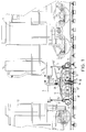
- FIG. 1 illustrates the rear part of a locomotive or driving rail vehicle 1 driving along the track a wagon 2 by means of a coupling 3.
- the track cleaning device is located, in this embodiment, between the power train 1 and the wagon 2.
- This cleaning device is in the form of a box 4 without bottom guided and carried by the rails by means of rollers 5.5 '.
- the box 4 is connected to the chassis of the rear part of the powerplant 1 and to the chassis of the front part of the wagon via 6.6 'lifting members such as hydraulic cylinders.
- the box 4 is driven along the track by a drawbar 7 attached to the power train 1.
- the jacks 6, 6 ' make it possible to raise the box 4 for walking up and down, for example.
- the box 4 is placed under vacuum by a suction device arranged in a waste container 12 located on the power train 1.
- the suction device comprises a cyclone associated with a suitable filter which makes it possible to retain the heaviest waste of first, then the dust then.
- the suction device is connected to the casing 4 via a suction duct 10 comprising a bellows 11 which makes it possible to compensate for the relative movements between the casing 4 and the powerplant 1.
- the upper part of the casing 4 receives a concave part 20 forming a suction hood which makes it possible to concentrate the waste towards the mouth of the suction duct 10.
- Rubber skirts 8.8 ′ surround the casing 4 in its lower part and promote the depression of the latter by increasing its tightness.
- Two 13,13 'shaped brushes are arranged inside the box 4 one in front of the other in the direction of the axis of the rail, so to overlap each row of rails.
- These brushes 13, 13 ′ are driven in rotation by motors and rotate in opposite directions with respect to each other as indicated by the arrows F.
- a brush 14 of smaller size driven in rotation by a motor 15 is arranged between the rail and the axis of the track.
- the axis of rotation 19 (fig. 2) of the brush 14 forms an acute angle with a vertical axis perpendicular to the plane formed by the rails. In this working position, only part of the periphery of the brush 14 is in contact with the ballast.
- This brush is tiltable by a device which will be described with reference to Figure 2 and which allows to bring the axis of rotation of the brush in a substantially vertical plane, so that the brush 14 is no longer in contact with the ballast .
- the box 4 also has two waste drawers 16,16 'fixed against the frame of the box respectively at the front and at the rear of the latter near the guide rollers 5,5'. The operation of the device will now be explained with reference to FIG. 2.
- the brushes 13, 13 ′ are rotated in opposite directions to one another so that their parts in contact with the rail move towards one another.
- the waste located near a line of rail is first brought to an area between the contact point of the brushes and the rail, then projected towards the upper part of the box 20.
- the most waste light once in this area are sucked by the suction device and are evacuated through the conduit 10.
- the heaviest waste such as metal grinding residue or the most bulky such as bottles for example are not sucked but driven by the movement of the brushes 13,13 ', and fall back into the lateral recovery drawers 16,16'.
- the central brush 14 has the function of projecting the waste located in the space contained between the longitudinal median axis of the track and a rail, in the direction of the brushes 13,13 'which drive them towards the upper zone of the box as described above.
- the axis 19 of the brush 14 forming an acute angle with a vertical axis in the working position, only a part of the periphery of the brush 14 is in contact with the ballast. In this way, by adapting the direction of rotation of the brush according to whether it is inclined forward or backward, the waste is projected tangentially to the periphery of the brush 14 in the direction of the space between the contact point of the brushes 13,13 'and the rail. Thus, it is possible with this equipment to process both the waste located directly near the rails and that located between the rails of a track.
- the angular position of the central brushes 14 can be adjusted by means of jacks 17 whose cylinder is integral with the chassis of the box 4 and whose rod actuates an intermediate piece 18 carrying the brush 14.
- the angle formed between the axis of rotation 19 of the brush 14 and a vertical axis perpendicular to the axis of the track is modified.
- Figure 3 shows in section how the brushes 13,13 'are shaped. These shaped brushes comprise on each side of the rail head fibers of sufficient length to reach the ground in the service position, while the central part of the brush which is in direct contact with the rail head fibers of a length suitable for flushing said mushroom in the working position.
- the arrows F1 and F2 of FIG. 3 indicate the direction of rotation of the central brushes 14, direction of rotation which results from the function which these brushes 14 fulfill, namely to bring back the waste situated in the center of the path towards the brushes 13,13 'to ensure their projection towards the upper zone 10 of suction of the box 4.
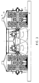
- FIGS 4,5 and 6 illustrate a second embodiment of the track cleaning equipment according to the present invention.
- the operating principle is identical to the first embodiment, however both the brushes 13, 13 'and the brush 14 are arranged so that they can be raised during work on the track.
- the front brushes 13 and rear brushes 13 ′ can be raised to the high position independently of one another.
- the central brush 14 is integral with the frame carrying the front brush 13 and is therefore liftable with the brush 13.
- This arrangement has the advantage of being able to raise one or the other of the brushes, for example to avoid an obstacle on the track without having to raise the whole box by means of the cylinders 6,6 '.
- known type obstacle detectors (not shown) can be incorporated to the equipment and order the automatic lifting of the brushes 13,14 or 13 'in the presence of an obstacle on the track.
- the brushes 13 ′ are mounted around an axis 22 carried by a support piece 23.
- This support piece 23 is pivoted at its end opposite the axis of the brush around a frame 24 integral with the casing 4.
- a motor 25 provided with a drive pinion 26 is fixed on a plate 27 arranged on the support piece 23.
- a second pinion 28 on the axis of the brush 22 allows the drive to rotate of the latter thanks to a chain or a toothed belt 29.
- a jack 30 whose cylinder is integral with the frame 24 and whose rod is fixed in the support piece 23 allows, when actuated, to raise the support piece 23 and therefore the brush 13 ′ in the high position as indicated by dotted lines on the right-hand side of FIG. 4.
- the support piece 23 has a lug 31 having a bore 32.
- a locking member 33 fixed to the upright 24 has an axis sliding 34 against the action of an elastic member e (fig. 5).
- e an elastic member
- the arrangement of the brushes 13 is identical to that described above.
- the support piece 23 also has at its end close to the axis 22 of the brush 13 a fixing plate 36 carrying the brush 14.
- the brush 14 is pivotally mounted around an axis 38 on a piece of holding 37.
- a jack 39 the cylinder of which is integral with the plate 36 and the rod of which is connected to the brush 14, makes it possible to vary the angular position of said brush in a vertical plane parallel to the axis of the track.
- the speed of rotation of the brushes 13, 13 ′ which rotate in opposite directions with respect to each other may be identical for each brush or, on the contrary, these speeds of rotation may be different.
- a servo-control (not shown) of the speed of the brushes 13, 13 ′, 14 as a function of the working speed of the equipment along the track, servo-control allowing the tangential speed of the periphery of each brush 13.13 'relative to the rail is the same regardless of the speed of movement of the equipment along the track.
- the central brush 14 has been shown in the drawings by a single brush of sufficient size to cover the entire space between the axis of the track and each rail. It is obvious that other arrangements are possible, for example by providing several brushes 14 of smaller dimension to more effectively cover the surface located between the axis of the track and each rail.
- FIG. 1 For reasons of space, the equipment has been shown in FIG. 1 between a locomotor vehicle 1 and a wagon 2, this equipment can naturally be arranged thanks to its reduced bulk under a self-propelled railway vehicle or be integrated into a trolley towed along the track.
Landscapes
- Engineering & Computer Science (AREA)
- Architecture (AREA)
- Civil Engineering (AREA)
- Structural Engineering (AREA)
- Cleaning In General (AREA)
- Cleaning Of Streets, Tracks, Or Beaches (AREA)
Abstract
Description
Les voies de chemins de fer, tramways, métros, etc., sont toujours encombrées par de nombreux déchets jetés par les usagers, surtout dans les stations. Ces déchets peuvent être très variés tels que billets, cartons, bouteilles, boîtes métalliques, papiers, etc. De plus, les voies sont également souillées par les résidus du reprofilage des rails qui s'effectue généralement par meulage, fraisage ou rabotage, et laisse donc des copeaux ou de la limaille sur la voie.Railways, trams, metros, etc. are always clogged with a lot of waste thrown by users, especially in stations. This waste can be very varied such as tickets, cartons, bottles, metal boxes, papers, etc. In addition, the tracks are also soiled by the residue from the reprofiling of the rails which is generally carried out by grinding, milling or planing, and therefore leaves chips or filings on the track.
Le nettoyage manuel, quelquefois encore pratiqué dans les stations, est lent, dangereux et coûteux. Ce mode de nettoyage, qui n'est pas envisageable tout au long de la voie, est également progressivement abandonné dans les stations au profit d'un nettoyage automatique à l'aide de machines.Manual cleaning, sometimes still practiced in stations, is slow, dangerous and expensive. This cleaning method, which cannot be envisaged all along the track, is also gradually abandoned in stations in favor of automatic cleaning using machines.
Il existe certaines machines de nettoyage des voies, par exemple celles décrites dans le document DE-27902047, qui sont composées d'un caisson central sans fond guidé et supporté par les rails. Ce caisson est mis en dépression par de puissants aspirateurs suivis de filtres recueillant les déchets. Ces machines ne sont pas satisfaisantes car elles ne sont efficaces que pour des objets légers, papiers, billets, etc., mais ne permettent pas de récupérer les boîtes, bouteilles, ni les copeaux ou la limaille. De plus, ces machines ont l'inconvénient de nécessiter une puissance très élevée, de l'ordre de 100 Kw pour le fonctionnement des aspirateurs.There are certain track cleaning machines, for example those described in document DE-27902047, which are composed of a central box without a guided bottom and supported by the rails. This box is put under vacuum by powerful vacuum cleaners followed by filters collecting the waste. These machines are not satisfactory because they are only effective for light objects, papers, tickets, etc., but do not allow boxes, bottles, shavings or filings to be recovered. In addition, these machines have the disadvantage of requiring a very high power, of the order of 100 Kw for operation. vacuum cleaners.
Le but de la présente invention est de permettre un nettoyage automatique, à l'aide d'une machine, des voies de chemin de fer, de tramway ou de métro, dans et hors des stations, qui ramasse aussi bien les déchets légers, papiers, billets, etc., que les déchets lourds, bouteilles, boîtes métalliques ainsi que la limaille et les copeaux provenant du reprofilage des rails.The object of the present invention is to allow automatic cleaning, using a machine, of the railway, tramway or metro tracks, in and out of stations, which also collects light waste, paper , tickets, etc., as heavy waste, bottles, metal cans as well as filings and chips from the reprofiling of the rails.
Un autre but de l'invention est de remplacer le ramassage manuel des déchets par un ramassage mécanique plus rapide, moins coûteux et surtout n'exposant pas le personnel aux dangers de la voie.Another object of the invention is to replace the manual collection of waste by a faster mechanical collection, less expensive and above all not exposing personnel to the dangers of the track.
Un autre but de l'invention est encore de réduire l'encombrement de la machine ou du dispositif de nettoyage de la voie et surtout d'en diminuer la puissance et la consommation.Another object of the invention is also to reduce the size of the machine or of the track cleaning device and above all to reduce its power and consumption.
La présente invention a pour objet un équipement mécanisé pour le nettoyage des voies de chemins de fer, tramways, métros, funiculaires, etc. tendant à obvier aux inconvénients précités des machines existantes et qui se distingue par les caractéristiques énumérées à la revendication 1.The present invention relates to mechanized equipment for cleaning railway tracks, trams, metros, funiculars, etc. tending to obviate the aforementioned drawbacks of existing machines and which is distinguished by the characteristics listed in claim 1.
Grâce à ces caractéristiques, et en particulier à l'action combinée des brosses de forme et d'un dispositif d'aspiration, on obtient un équipement compact permettant d'éliminer tous les déchets encombrant une voie de chemin de fer quelque soit leur nature et/ou leur emplacement sur la voie avec une puissance nécessaire sensiblement réduite par rapport aux machines existantes.Thanks to these characteristics, and in particular to the combined action of the shape brushes and of a suction device, a compact equipment is obtained making it possible to eliminate all the waste cluttering up a railway track whatever their nature and / or their location on the track with a significantly reduced power requirement compared to existing machines.
Le dessin annexé illustre schématiquement et à titre d'exemple deux formes d'exécution de l'équipement de nettoyage des voies selon l'invention.The attached drawing illustrates schematically and by way of example two embodiments of the track cleaning equipment according to the invention.
La figure 1 illustre partiellement une motrice d'un train de service accouplée à un wagon, la machine portant une partie de l'équipement de nettoyage tandis qu'une autre partie de celui-ci est disposée entre la motrice et le wagon et tractée par ladite motrice le long de la voie.FIG. 1 partially illustrates a power train of a service train coupled to a wagon, the machine carrying part of the cleaning equipment while another part of this is placed between the power train and the wagon and towed by said motor car along the track.
La figure 2 illustre à plus grande échelle la partie tractée le long de la voie de l'équipement de nettoyage dans une exécution où celui-ci est agencé dans un véhicule tracté.Figure 2 illustrates on a larger scale the portion towed along the track of the cleaning equipment in an execution where it is arranged in a towed vehicle.
La figure 3 est une vue en coupe selon la ligne A-A de la figure 2.FIG. 3 is a sectional view along line A-A of FIG. 2.
La figure 4 est une vue similaire à la figure 2 d'une seconde forme d'exécution de l'équipement de nettoyage.Figure 4 is a view similar to Figure 2 of a second embodiment of the cleaning equipment.
La figure 5 est une coupe selon la ligne B-B de la figure 4.FIG. 5 is a section along line B-B in FIG. 4.
La figure 6 est une coupe selon la ligne C-C de la figure 4.FIG. 6 is a section along line C-C of FIG. 4.
La partie droite de la figure 1 illustre la partie arrière d'un véhicule ferroviaire locomoteur ou motrice 1 entraînant le long de la voie un wagon 2 par l'intermédiaire d'un accouplement 3. Le dispositif de nettoyage des voies est situé, dans cette forme d'exécution, entre la motrice 1 et le wagon 2. Ce dispositif de nettoyage se présente sous la forme d'un caisson 4 sans fond guidé et porté par les rails au moyen de galets 5,5'. Le caisson 4 est relié au châssis de la partie arrière de la motrice 1 et au châssis de la partie avant du wagon par l'intermédiaire d'organes de relevage 6,6' comme des vérins hydrauliques. Le caisson 4 est entraîné le long de la voie par un timon 7 rattaché à la motrice 1. Les vérins 6,6' permettent de relever le caisson 4 pour la marche haut-le-pied par exemple. Le caisson 4 est mis en dépression par un dispositif d'aspiration agencé dans un container à déchet 12 situé sur la motrice 1. Le dispositif d'aspiration comprend un cyclone associé à un filtre adapté qui permet de retenir les déchets les plus lourds d'abord, puis les poussières ensuite. Le dispositif d'aspiration est relié au caisson 4 par l'intermédiaire d'un conduit d'aspiration 10 comportant un soufflet 11 qui permet de compenser les mouvements relatifs entre le caisson 4 et la motrice 1.The right part of FIG. 1 illustrates the rear part of a locomotive or driving rail vehicle 1 driving along the track a
La partie supérieure du caisson 4 reçoit une pièce concave 20 formant une hotte d'aspiration qui permet de concentrer les déchets vers l'embouchure du conduit d'aspiration 10. Des jupes en caoutchouc 8,8' entourent le caisson 4 dans sa partie inférieure et favorisent la mise en dépression de ce dernier en augmentant son étanchéité.The upper part of the
Deux brosses de forme 13,13', dont les fibres sont généralement réalisées en matière plastique ou en acier, sont agencées à l'intérieur du caisson 4 l'une devant l'autre dans le sens de l'axe du rail, de manière à chevaucher chaque file de rails. Ces brosses 13,13' sont entraînées en rotation par des moteurs et tournent en sens inverse l'une par rapport à l'autre comme indiqué par les flèches F. Une brosse 14 de plus petite dimension entraînée en rotation par un moteur 15 est agencée entre le rail et l'axe de la voie. En position de service, l'axe de rotation 19 (fig. 2) de la brosse 14 forme un angle aigu avec un axe vertical perpendiculaire au plan formé par les rails. Dans cette position de travail, seule une partie de la périphérie de la brosse 14 est en contact avec le ballast. Cette brosse est inclinable par un dispositif qui sera décrit en référence à la figure 2 et qui permet d'amener l'axe de rotation de la brosse dans un plan sensiblement vertical, de sorte que la brosse 14 ne soit plus en contact avec le ballast. Le caisson 4 comporte encore deux tiroirs à déchets 16,16' fixés contre le bâti du caisson respectivement à l'avant et à l'arrière de ce dernier à proximité des galets de guidage 5,5'. Le fonctionnement du dispositif va maintenant être exposé en référence à la figure 2.Two 13,13 'shaped brushes, the fibers of which are generally made of plastic or steel, are arranged inside the
Les brosses 13, 13' sont entraînées en rotation en sens inverse l'une de l'autre de sorte que leurs parties en contact avec le rail se déplacent l'une vers l'autre. De cette façon, les déchets situés à proximité d'une file de rail sont ramenés tout d'abord dans une zone située entre le point de contact des brosses et le rail, puis projetés vers la partie supérieure du caisson 20. Les déchets les plus légers une fois dans cette zone sont aspirés par le dispositif d'aspiration et sont évacués par le conduit 10. Les déchets les plus lourds comme des résidus de meulage métallique ou les plus encombrants comme des bouteilles par exemple ne sont pas aspirés mais entraînés par le mouvement des brosses 13,13', et retombent dans les tiroirs de récupération latéraux 16,16'. La brosse centrale 14 a pour fonction de projeter les déchets situés dans l'espace contenu entre l'axe médian longitudinal de la voie et un rail, en direction des brosses 13,13' qui les entraînent vers la zone supérieure du caisson comme décrit ci-dessus. L'axe 19 de la brosse 14 formant un angle aigu avec un axe vertical en position de travail, seule une partie de la périphérie de la brosse 14 est en contact avec le ballast. De cette façon, en adaptant le sens de rotation de la brosse selon qu'elle est inclinée vers l'avant ou vers l'arrière, les déchets sont projetés tangentiellement à la périphérie de la brosse 14 en direction de l'espace compris entre le point de contact des brosses 13,13' et le rail. Ainsi, il est possible avec cet équipement de traiter aussi bien les déchets situés directement à proximité des rails que ceux situés entre les rails d'une voie.The
Grâce à l'action des brosses 13,13', qui permettent d'amener les déchets dans la zone supérieure du caisson, et donc directement à proximité du conduit d'aspiration 10, il n'est pas nécessaire de disposer d'une puissance d'aspiration importante comme dans les machines existantes. A titre d'exemple, une puissance d'aspiration d'environ 20 Kw est suffisante pour éliminer les déchets.Thanks to the action of the
Comme on le voit sur la figure 2, la position angulaire des brosses centrales 14 peut être ajustée grâce à des vérins 17 dont le cylindre est solidaire du châssis du caisson 4 et dont la tige actionne une pièce intermédiaire 18 portant la brosse 14. En actionnant le vérin 17, on modifie l'angle formé entre l'axe de rotation 19 de la brosse 14 et un axe vertical perpendiculaire à l'axe de la voie. En ajustant cette position, on peut optimiser la projection des déchets vers les brosses de grand diamètre 13,13 et éventuellement compenser les effets d'une usure irrégulière des brosses 14.As can be seen in FIG. 2, the angular position of the
La figure 3 montre en coupe de quelle façon les brosses 13,13' sont conformées. Ces brosses de forme comportent de part et d'autre du champignon du rail des fibres d'une longueur suffisante pour atteindre le sol en position de service, alors que la partie centrale de la brosse qui est en contact direct avec le champignon du rail comporte des fibres d'une longueur adaptée pour affleurer ledit champignon en position de travail. Les flèches F1 et F2 de la figure 3 indiquent le sens de rotation des brosses centrales 14, sens de rotation qui découle de la fonction que remplissent ces brosses 14, à savoir ramener les déchets situés au centre de la voie vers les brosses 13,13' pour assurer leur projection vers la zone supérieure 10 d'aspiration du caisson 4.Figure 3 shows in section how the
Les figures 4,5 et 6 illustrent une deuxième forme d'exécution de l'équipement de nettoyage des voies selon la présente invention. Le principe de fonctionnement est identique à la première forme d'exécution, cependant aussi bien les brosses 13,13' que la brosse 14 sont agencées de manière à pouvoir être relevées lors du travail en voie. Les brosses avant 13 et arrière 13' peuvent être relevées en position haute indépendamment l'une de l'autre. La brosse centrale 14 est solidaire du bâti portant la brosse avant 13 et est donc relevable avec la brosse 13. Cet agencement présente l'avantage de pouvoir relever l'une ou l'autre des brosses, par exemple pour éviter un obstacle sur la voie sans avoir à relever tout le caisson au moyen des vérins 6,6'. A ce propos, des détecteurs (non représentés) d'obstacles de type connu peuvent être incorporés à l'équipement et commander le relevage automatique des brosses 13,14 ou 13' en présence d'un obstacle sur la voie.Figures 4,5 and 6 illustrate a second embodiment of the track cleaning equipment according to the present invention. The operating principle is identical to the first embodiment, however both the
En référence à la figure 4, les brosses 13' sont montées autour d'un axe 22 porté par une pièce de support 23. Cette pièce de support 23 est pivotée à son extrémité opposée à l'axe de la brosse autour d'un cadre 24 solidaire du caisson 4. Un moteur 25 muni d'un pignon d'entraînement 26 est fixé sur un plaque 27 agencée sur la pièce de support 23. Un deuxième pignon 28 sur l'axe de la brosse 22 permet l'entraînement en rotation de cette dernière grâce à une chaîne ou une courroie crantée 29. Un vérin 30 dont le cylindre est solidaire du cadre 24 et dont la tige est fixée dans la pièce de support 23 permet, lorsqu'il est actionné, de relever la pièce de support 23 et donc la brosse 13' en position haute comme indiqué en pointillés sur la partie droite de la figure 4. La pièce de support 23 présente un ergot 31 comportant un alésage 32. Un organe de verrouillage 33 fixé sur le montant 24 comporte un axe coulissant 34 contre l'action d'un organe élastique (fig. 5). Lorsque la pièce de support 23 est en position relevée, l'ergot 31 s'engage dans un évidement 35 de l'organe de verrouillage 33 et l'axe 34 s'engage dans l'alésage 32 de l'ergot 31 assurant de ce fait un verrouillage fiable de la pièce de support 23.With reference to FIG. 4, the
L'agencement des brosses 13 est identique à celui décrit ci-dessus. La pièce de support 23 comporte encore à son extrémité proche de l'axe 22 de la brosse 13 une plaque de fixation 36 portant la brosse 14. La brosse 14 est montée pivotante autour d'un axe 38 sur une pièce de maintien 37. Un vérin 39, dont le cylindre est solidaire de la plaque 36 et dont la tige est reliée à la brosse 14, permet de faire varier la position angulaire de ladite brosse dans un plan vertical parallèle à l'axe de la voie.The arrangement of the
La vitesse de rotation des brosses 13,13' qui tournent en sens inverse l'une par rapport à l'autre peut être identique pour chaque brosse ou au contraire ces vitesses de rotation peuvent être différentes. Il est également prévu un asservissement (non représenté) de la vitesse des brosses 13,13',14 en fonction de la vitesse de travail de l'équipement le long de la voie, asservissement permettant que la vitesse tangentielle de la périphérie de chaque brosse 13,13' par rapport au rail soit la même quelle que soit la vitesse de déplacement de l'équipement le long de la voie.The speed of rotation of the
La brosse centrale 14 a été représentée sur les dessins par une seule brosse d'une taille suffisante pour couvrir tout l'espace situé entre l'axe de la voie et chaque rail. Il est évident que d'autres agencements sont possibles, par exemple en prévoyant plusieurs brosses 14 de plus petite dimension pour couvrir plus efficacement la surface située entre l'axe de la voie et chaque rail.The
Pour des raisons de place, l'équipement a été représenté à la figure 1 entre un véhicule locomoteur 1 et un wagon 2, cet équipement peut naturellement être agencé grâce à son encombrement réduit sous un véhicule ferroviaire auto-moteur ou être intégré à un chariot remorqué le long de la voie.For reasons of space, the equipment has been shown in FIG. 1 between a locomotor vehicle 1 and a
Claims (14)
Applications Claiming Priority (2)
| Application Number | Priority Date | Filing Date | Title |
|---|---|---|---|
| CH142495 | 1995-05-16 | ||
| CH1424/95 | 1995-05-16 |
Publications (1)
| Publication Number | Publication Date |
|---|---|
| EP0743399A1 true EP0743399A1 (en) | 1996-11-20 |
Family
ID=4210140
Family Applications (1)
| Application Number | Title | Priority Date | Filing Date |
|---|---|---|---|
| EP96104266A Withdrawn EP0743399A1 (en) | 1995-05-16 | 1996-03-18 | Track cleaning apparatus |
Country Status (6)
| Country | Link |
|---|---|
| US (1) | US5673626A (en) |
| EP (1) | EP0743399A1 (en) |
| JP (1) | JPH08338012A (en) |
| AU (1) | AU5220696A (en) |
| CA (1) | CA2173565A1 (en) |
| ZA (1) | ZA963469B (en) |
Cited By (7)
| Publication number | Priority date | Publication date | Assignee | Title |
|---|---|---|---|---|
| CH692855A5 (en) * | 1996-07-22 | 2002-11-29 | Pete Hirsch | Equipment for cleaning railway tracks is formed as vehicle with suitably formed wheels for track negotiation and at least one brush for track cleaning |
| WO2011057689A1 (en) * | 2009-11-11 | 2011-05-19 | Franz Plasser Bahnbaumschinen-Industriegesellschaft Mbh | Machine for processing a track |
| CN102363954A (en) * | 2011-11-19 | 2012-02-29 | 昆明中铁大型养路机械集团有限公司 | Railway ballast bed side dirt blowing and sucking device |
| FR2999621A1 (en) * | 2012-12-18 | 2014-06-20 | Const Mecaniques Et Automatisations Rivard | Cleaning machine for cleaning circulation rail of urban area tram during regular maintenance of grooves of rail, has communication circuit comprising filtration unit and transfer pumping unit for transferring contents from tank in chamber |
| CN112215131A (en) * | 2020-10-10 | 2021-01-12 | 李睿宸 | Automatic garbage picking system and manual operation and automatic picking method thereof |
| CN112774928A (en) * | 2021-01-04 | 2021-05-11 | 常州伊科达弹簧制造有限公司 | Stainless steel spring drying and cleaning device |
| CN113731882A (en) * | 2021-09-06 | 2021-12-03 | 合肥市春华起重机械有限公司 | Track cleaning equipment for double-beam crane |
Families Citing this family (21)
| Publication number | Priority date | Publication date | Assignee | Title |
|---|---|---|---|---|
| US6134734A (en) * | 1997-01-21 | 2000-10-24 | Marrero; Lou | Aircraft maintenance apparatus and method of maintaining aircraft |
| DE29824935U1 (en) * | 1997-10-20 | 2003-06-26 | Florianer Bahn Forschungs- Und Errichtungsgesellschaft M.B.H., St. Florian | Rail-track groove cleaning unit |
| JP2000325673A (en) * | 1999-05-18 | 2000-11-28 | Tomy Co Ltd | Cleaning rolling stock model |
| CA2450827C (en) * | 2003-12-23 | 2005-03-22 | Trak Tek Canada Inc. | Machine for clearing grooves including railroad flangeways |
| GB2417470B (en) * | 2004-08-27 | 2007-08-15 | Jensen | An overhead rail cleaner |
| JP4502872B2 (en) * | 2005-04-26 | 2010-07-14 | 十三 松井 | Track and road work vehicle |
| NL1031217C2 (en) * | 2006-02-22 | 2007-12-11 | Ginkel Groep B V Van | Sandblasting method for rails on railway track, involves moving nozzle along length of rail while collecting particles for reuse on same rail section |
| CN100572675C (en) * | 2007-08-24 | 2009-12-23 | 中国国际海运集装箱(集团)股份有限公司 | Guide rail upper surface clearing apparatus |
| KR100854510B1 (en) * | 2008-04-03 | 2008-08-26 | 주식회사 한성기건 | Air purge apparatus for rail track |
| JP5087041B2 (en) * | 2009-04-08 | 2012-11-28 | 三菱重工業株式会社 | Guide rail-type vehicle track removal device |
| CN101829662B (en) * | 2010-05-17 | 2012-06-06 | 哈尔滨工程大学 | Cleaning device for ship model towing tank trailer tracks |
| ES1073525Y (en) * | 2010-10-27 | 2011-03-21 | Eriste 2007 Inversiones S L | EQUIPMENT FOR CLEANING BY ASPIRATION OF TRAIL RAILS |
| US8371229B1 (en) * | 2011-07-12 | 2013-02-12 | Michael A. Sailor | Track cleaning car |
| CN102861729A (en) * | 2012-09-29 | 2013-01-09 | 青岛前湾联合集装箱码头有限责任公司 | Automatic cleaning machine |
| US10335701B2 (en) * | 2014-04-07 | 2019-07-02 | Korea Bass Co., Ltd. | Model railcar for cleaning model train track |
| CN108951526A (en) * | 2018-08-09 | 2018-12-07 | 中车山东机车车辆有限公司 | Suction-type sewer scavenger is cleaned by the tunnel of electrician's condition suitable for third rail |
| CN108994032A (en) * | 2018-08-21 | 2018-12-14 | 佛山职业技术学院 | A kind of inter-bank carrying platform of robot cleaner for photovoltaic module |
| CN111731339B (en) * | 2020-07-08 | 2022-08-26 | 温州职业技术学院 | Multifunctional foreign matter cleaning device for rail transit |
| CN112900345B (en) * | 2021-01-19 | 2024-03-26 | 张润申 | Cleaning device for rail transit and application method thereof |
| CN113026655A (en) * | 2021-03-27 | 2021-06-25 | 蔡良云 | Recreation ground train track cleaning robot |
| CN117862093B (en) * | 2024-03-12 | 2024-05-03 | 珠海市玛斯特五金塑胶制品有限公司 | Automatic cleaning process and equipment for silent coating of guide rail |
Citations (3)
| Publication number | Priority date | Publication date | Assignee | Title |
|---|---|---|---|---|
| DE1759817A1 (en) * | 1968-06-11 | 1971-07-15 | Bergische Stahlindustrie | Device for rail vehicles to improve static friction |
| DE8913287U1 (en) * | 1989-09-16 | 1990-01-11 | Hermann Wiebe Grundstuecks- Und Maschinenanlagen Kg, 2800 Bremen | Rail vehicle with cleaning device |
| EP0378025A1 (en) * | 1988-12-29 | 1990-07-18 | G.I.E. PROTEE Groupement d'intérêt économique | Apparatus and process for cleaning a horizontal surface |
Family Cites Families (5)
| Publication number | Priority date | Publication date | Assignee | Title |
|---|---|---|---|---|
| US815308A (en) * | 1905-10-05 | 1906-03-13 | William H Perry | Rotary fender and cleaner for surface railways. |
| US4741072A (en) * | 1987-02-17 | 1988-05-03 | Wilkerson Kenneth R | Railroad track cleaner |
| IT1245946B (en) * | 1990-11-15 | 1994-11-07 | Costamasnaga Spa | BIVALENT VEHICLE FOR THE CLEANING OF ROADS AND RAILS, IN PARTICULAR RAILWAYS |
| DE59405685D1 (en) * | 1993-07-08 | 1998-05-20 | Plasser Bahnbaumasch Franz | Sweeper for sweeping a track |
| US5579553A (en) * | 1995-07-17 | 1996-12-03 | Holley Engineering Company, Inc. | Ballast broom with auger and method |
-
1996
- 1996-03-18 EP EP96104266A patent/EP0743399A1/en not_active Withdrawn
- 1996-03-20 US US08/618,549 patent/US5673626A/en not_active Expired - Fee Related
- 1996-04-04 CA CA002173565A patent/CA2173565A1/en not_active Abandoned
- 1996-05-02 ZA ZA963469A patent/ZA963469B/en unknown
- 1996-05-13 AU AU52206/96A patent/AU5220696A/en not_active Abandoned
- 1996-05-14 JP JP8119136A patent/JPH08338012A/en active Pending
Patent Citations (3)
| Publication number | Priority date | Publication date | Assignee | Title |
|---|---|---|---|---|
| DE1759817A1 (en) * | 1968-06-11 | 1971-07-15 | Bergische Stahlindustrie | Device for rail vehicles to improve static friction |
| EP0378025A1 (en) * | 1988-12-29 | 1990-07-18 | G.I.E. PROTEE Groupement d'intérêt économique | Apparatus and process for cleaning a horizontal surface |
| DE8913287U1 (en) * | 1989-09-16 | 1990-01-11 | Hermann Wiebe Grundstuecks- Und Maschinenanlagen Kg, 2800 Bremen | Rail vehicle with cleaning device |
Cited By (9)
| Publication number | Priority date | Publication date | Assignee | Title |
|---|---|---|---|---|
| CH692855A5 (en) * | 1996-07-22 | 2002-11-29 | Pete Hirsch | Equipment for cleaning railway tracks is formed as vehicle with suitably formed wheels for track negotiation and at least one brush for track cleaning |
| WO2011057689A1 (en) * | 2009-11-11 | 2011-05-19 | Franz Plasser Bahnbaumschinen-Industriegesellschaft Mbh | Machine for processing a track |
| CN102363954A (en) * | 2011-11-19 | 2012-02-29 | 昆明中铁大型养路机械集团有限公司 | Railway ballast bed side dirt blowing and sucking device |
| CN102363954B (en) * | 2011-11-19 | 2013-08-21 | 昆明中铁大型养路机械集团有限公司 | Railway ballast bed side dirt blowing and sucking device |
| FR2999621A1 (en) * | 2012-12-18 | 2014-06-20 | Const Mecaniques Et Automatisations Rivard | Cleaning machine for cleaning circulation rail of urban area tram during regular maintenance of grooves of rail, has communication circuit comprising filtration unit and transfer pumping unit for transferring contents from tank in chamber |
| CN112215131A (en) * | 2020-10-10 | 2021-01-12 | 李睿宸 | Automatic garbage picking system and manual operation and automatic picking method thereof |
| CN112774928A (en) * | 2021-01-04 | 2021-05-11 | 常州伊科达弹簧制造有限公司 | Stainless steel spring drying and cleaning device |
| CN112774928B (en) * | 2021-01-04 | 2024-06-07 | 常州伊科达航天科技有限公司 | Stainless steel spring drying and cleaning device |
| CN113731882A (en) * | 2021-09-06 | 2021-12-03 | 合肥市春华起重机械有限公司 | Track cleaning equipment for double-beam crane |
Also Published As
| Publication number | Publication date |
|---|---|
| CA2173565A1 (en) | 1996-11-17 |
| US5673626A (en) | 1997-10-07 |
| ZA963469B (en) | 1996-11-13 |
| JPH08338012A (en) | 1996-12-24 |
| AU5220696A (en) | 1996-11-28 |
Similar Documents
| Publication | Publication Date | Title |
|---|---|---|
| EP0743399A1 (en) | Track cleaning apparatus | |
| EP0668398B1 (en) | Device for reshaping railway rails | |
| EP0668397B1 (en) | Device for reshaping railway rails | |
| FR2668510A1 (en) | MACHINE FOR DETACHING ANCHORING DEVICES FROM A RAIL ON THE TRAVERSES. | |
| FR2532968A1 (en) | TOOL ARRANGEMENT FOR BOTTOM UNDER BOTTOM, LEVELING AND LATERAL DRESSING OF A RAILWAY | |
| CA2370486C (en) | Motorized road vehicle for digging trenches in the ground | |
| FR2476708A1 (en) | MOBILE ASSEMBLY FOR CLEANING THE RAILWAY BALLAST LAYER AND CLEANING METHOD USING SUCH AN ASSEMBLY | |
| FR2700785A1 (en) | Stuffing machine. | |
| FR2483481A1 (en) | RAILWAY CONSTRUCTION MACHINE COMPRISING SUPPORTS FOR LIFTING AND DRESSING TOOLS | |
| FR2620147A1 (en) | RAILWAY CONSTRUCTION MACHINE MOVABLE BY CONTINUOUSLY ROLLING (WITHOUT STOPPING) | |
| FR2553124A1 (en) | ROLLING MACHINE FOR STOCKING, LEVELING, AND RAIL TRACKING | |
| EP0849397A1 (en) | Device for the continuous finishing of the reprofiling of the head of a railway rail | |
| FR2463228A1 (en) | MOBILE MACHINE ON A RAILWAY TRACK TO ELIMINATE RAIL SURFACE DEFECTS | |
| EP0675227A1 (en) | Grinding machine for localised sections of railway rail, more specifically for end-to-end weldings or other local defects | |
| FR2699197A1 (en) | Machine for sucking ballast from a track ballast bed. | |
| CA1225823A (en) | Apparatus for deburring a product cast by continuous process | |
| EP0556161A1 (en) | Rolling device for railways | |
| FR2687698A1 (en) | INSTALLATION FOR BALLASTING AND STACKING BELOW A RAILWAY. | |
| EP0089907B1 (en) | Grinding machine for electric and similar collectors | |
| EP0606787B1 (en) | Apparatus for treating the rolling surface of rails, more specifically for descaling and grinding short pitch corrugations | |
| FR2663056A1 (en) | Machine for picking up objects | |
| FR2862992A3 (en) | Tamping machine for railway tracks has two double-sleeper tamping devices for simultaneous tamping of four sleepers, located between track lifting machine and bogie unit for machine frame | |
| EP0378025A1 (en) | Apparatus and process for cleaning a horizontal surface | |
| FR2632334A1 (en) | Sewage cleaning device, in particular for cleaning a sewerage in normal service | |
| FR2728811A3 (en) | Suction surface cleaning notably public paths and roads |
Legal Events
| Date | Code | Title | Description |
|---|---|---|---|
| PUAI | Public reference made under article 153(3) epc to a published international application that has entered the european phase |
Free format text: ORIGINAL CODE: 0009012 |
|
| AK | Designated contracting states |
Kind code of ref document: A1 Designated state(s): AT BE CH DE FR GB IT LI NL SE |
|
| 17P | Request for examination filed |
Effective date: 19970226 |
|
| STAA | Information on the status of an ep patent application or granted ep patent |
Free format text: STATUS: THE APPLICATION IS DEEMED TO BE WITHDRAWN |
|
| 18D | Application deemed to be withdrawn |
Effective date: 19981001 |