EP2497732A2 - Enrouleur de filature - Google Patents
Enrouleur de filature Download PDFInfo
- Publication number
- EP2497732A2 EP2497732A2 EP20120157704 EP12157704A EP2497732A2 EP 2497732 A2 EP2497732 A2 EP 2497732A2 EP 20120157704 EP20120157704 EP 20120157704 EP 12157704 A EP12157704 A EP 12157704A EP 2497732 A2 EP2497732 A2 EP 2497732A2
- Authority
- EP
- European Patent Office
- Prior art keywords
- yarn
- yarns
- guides
- godet roller
- alignment directions
- Prior art date
- Legal status (The legal status is an assumption and is not a legal conclusion. Google has not performed a legal analysis and makes no representation as to the accuracy of the status listed.)
- Granted
Links
- 238000009987 spinning Methods 0.000 title claims abstract description 33
- 238000004804 winding Methods 0.000 claims description 51
- 238000003780 insertion Methods 0.000 description 2
- 230000037431 insertion Effects 0.000 description 2
- 238000005452 bending Methods 0.000 description 1
- 230000003247 decreasing effect Effects 0.000 description 1
- 238000009434 installation Methods 0.000 description 1
- 230000002452 interceptive effect Effects 0.000 description 1
- 238000004519 manufacturing process Methods 0.000 description 1
- 238000012986 modification Methods 0.000 description 1
- 230000004048 modification Effects 0.000 description 1
- 238000011144 upstream manufacturing Methods 0.000 description 1
Images


Classifications
-
- B—PERFORMING OPERATIONS; TRANSPORTING
- B65—CONVEYING; PACKING; STORING; HANDLING THIN OR FILAMENTARY MATERIAL
- B65H—HANDLING THIN OR FILAMENTARY MATERIAL, e.g. SHEETS, WEBS, CABLES
- B65H67/00—Replacing or removing cores, receptacles, or completed packages at paying-out, winding, or depositing stations
- B65H67/04—Arrangements for removing completed take-up packages and or replacing by cores, formers, or empty receptacles at winding or depositing stations; Transferring material between adjacent full and empty take-up elements
- B65H67/044—Continuous winding apparatus for winding on two or more winding heads in succession
- B65H67/048—Continuous winding apparatus for winding on two or more winding heads in succession having winding heads arranged on rotary capstan head
-
- B—PERFORMING OPERATIONS; TRANSPORTING
- B65—CONVEYING; PACKING; STORING; HANDLING THIN OR FILAMENTARY MATERIAL
- B65H—HANDLING THIN OR FILAMENTARY MATERIAL, e.g. SHEETS, WEBS, CABLES
- B65H51/00—Forwarding filamentary material
- B65H51/02—Rotary devices, e.g. with helical forwarding surfaces
- B65H51/04—Rollers, pulleys, capstans, or intermeshing rotary elements
- B65H51/06—Rollers, pulleys, capstans, or intermeshing rotary elements arranged to operate singly
-
- B—PERFORMING OPERATIONS; TRANSPORTING
- B65—CONVEYING; PACKING; STORING; HANDLING THIN OR FILAMENTARY MATERIAL
- B65H—HANDLING THIN OR FILAMENTARY MATERIAL, e.g. SHEETS, WEBS, CABLES
- B65H57/00—Guides for filamentary materials; Supports therefor
- B65H57/003—Arrangements for threading or unthreading the guide
-
- B—PERFORMING OPERATIONS; TRANSPORTING
- B65—CONVEYING; PACKING; STORING; HANDLING THIN OR FILAMENTARY MATERIAL
- B65H—HANDLING THIN OR FILAMENTARY MATERIAL, e.g. SHEETS, WEBS, CABLES
- B65H57/00—Guides for filamentary materials; Supports therefor
- B65H57/16—Guides for filamentary materials; Supports therefor formed to maintain a plurality of filaments in spaced relation
-
- B—PERFORMING OPERATIONS; TRANSPORTING
- B65—CONVEYING; PACKING; STORING; HANDLING THIN OR FILAMENTARY MATERIAL
- B65H—HANDLING THIN OR FILAMENTARY MATERIAL, e.g. SHEETS, WEBS, CABLES
- B65H57/00—Guides for filamentary materials; Supports therefor
- B65H57/28—Reciprocating or oscillating guides
-
- B—PERFORMING OPERATIONS; TRANSPORTING
- B65—CONVEYING; PACKING; STORING; HANDLING THIN OR FILAMENTARY MATERIAL
- B65H—HANDLING THIN OR FILAMENTARY MATERIAL, e.g. SHEETS, WEBS, CABLES
- B65H2701/00—Handled material; Storage means
- B65H2701/30—Handled filamentary material
- B65H2701/31—Textiles threads or artificial strands of filaments
- B65H2701/313—Synthetic polymer threads
- B65H2701/3132—Synthetic polymer threads extruded from spinnerets
Definitions
- the present invention relates to a spinning winder for winding a plurality of yarns spun out from a spinning unit onto a plurality of bobbins attached to a winding axis.
- a spinning winder recited in Patent Literature 1 ( WO2008/138827 ) is arranged so that a plurality of yarns spun out from a spinning unit are wound while being aligned side by side along the axes of godet rollers, and then wound respectively onto a plurality of bobbins which are attached in series to a winding axis which extends in directions orthogonal to the axes of the godet rollers.
- a plurality of distribution guides are provided along the winding axis, on the upstream of the bobbins in the yarn running direction.
- the last godet roller is arranged to be movable relative to the distribution guides, and the yarns are distributed to the distribution guides by the movement of the last godet roller. More specifically, as shown in Fig. 6 and Fig. 7 of Patent Literature 1, the godet roller is arranged to be movable along the alignment directions of the distribution guides (i.e., the axial directions of the winding axis) between a yarn winding position (indicated by full lines) for winding the yarns and a position (indicated by dotted lines; hereinafter, yarn threading start position) which is away from the yarn winding position and where the godet roller is outside the position of the spinning winder at the time of winding yarns.
- the godet roller on which the yarns are threaded is moved in an alignment direction, so that the yarns are moved to the corresponding distribution guides and the yarn threading is carried out.
- the godet roller is fixed whereas the distribution guides are arranged to be movable along the axial directions of the winding axis between a yarn winding position (indicated by full lines) for winding the yarns and a position (indicated by dotted lines; hereinafter, yarn threading start position) which is away from the yarn winding position and where the distribution guides are outside the position of the spinning winder at the time of winding yarns.
- the yarns are moved to the corresponding distribution guides and the yarn threading is carried out.
- Patent Literature 1 The spinning winder recited in Patent Literature 1, however, is disadvantageous in that, because the godet roller or the distribution guides is/are arranged to be movable to move the yarns to the corresponding distribution guides, a very large installation area is required when the movable range of the godet rollers or the distribution guides which are outside the spinning winder at the position of winding yarns is taken into account, and hence the design freedom is limited.
- An object of the present invention is therefore to provide a spinning winder in which yarns threaded on a godet roller are fed to corresponding distribution guides by a simple structure.
- a spinning winder of the present invention includes: a godet roller on which a plurality of yarns supplied from a spinning unit are wound while being aligned in directions in parallel to an axis of the godet roller; a winding axis to which a plurality of bobbins are attached in series along the same, the winding axis winding the yarns supplied from the godet roller onto the respective bobbins; a plurality of distribution guides which are disposed in predetermined alignment directions in parallel to the winding axis and distribute the yarns supplied from the godet roller to the respective bobbins attached to the winding axis; and a yarn holding component which is arranged to be movable in the alignment directions of the distribution guides while holding the yarns.
- this spinning winder of the present invention a small and light yarn holding component holding the yarns is used, and this yarn holding component is moved in an alignment direction along the distribution guides while the godet roller and the distribution guides are kept unmoved. With this, the yarns are fed to the corresponding distribution guides by a simple structure.
- each of the distribution guides includes a yarn threading portion to which a yarn is threaded from one side in the alignment directions, and the yarn holding component is arranged to be movable in an inclined direction which is between the alignment directions and directions orthogonal to the alignment directions, and to move in the inclined direction from said one side to the other side of the distribution guides while holding the yarns to be aligned in directions orthogonal to the alignment directions.
- the yarns held by the yarn holding component are aligned in directions orthogonal to the alignment directions of the distribution guides, and each yarn can be threaded onto the yarn threading portion of the distribution guide from one side in the alignment directions. For this reason, by moving the yarn holding component holding the yarns in the inclined direction from one side to the other side in the alignment directions, it is possible to serially thread the yarns held by the yarn holding component onto the respective distribution guides from one side in the alignment directions.
- the axis of the godet roller intersects with the alignment directions, and the yarn holding component moves along the alignment directions from the other side to said one side of the distribution guides, and then moves in the inclined direction from said one side to the other side of the distribution guides.
- the yarns are serially threaded onto the distribution guides from one side in the alignment directions in such a way that, after the yarn holding component is moved along the alignment directions to position the yarns held by the yarn holding component at one side of the distribution guides, the yarn holding component is moved in the inclined direction.
- the yarn holding component is a rod-shaped component extending in directions intersecting with the alignment directions
- the rod-shaped component has, on its outer circumference, grooves at least on one side of the rod-shaped component in the alignment directions, and the grooves are formed at intervals in axial directions of the rod-shaped component to correspond to the respective yarns.
- the yarn holding component when the yarn holding component is moved along the alignment directions from the other side to the one side of the distribution guides so as to position the yarns on the one side of the distribution guides, the yarns are held as entering one side of the grooves of the yarn holding component in the alignment directions.
- the yarn holding component holding the yarns is moved in the inclined direction from the one side to the other side of the distribution guides, the yarns entering the grooves of the yarn holding component are passed to the yarn threading portions of the distribution guides because the direction in which the yarn enters the groove of the yarn holding component is identical with the direction in which the yarn is threaded onto the yarn threading portion of the distribution guide.
- the godet roller is arranged to be movable between a yarn winding position where the yarns are wound onto the winding axis and a yarn threading position which is close to the yarn holding component at the retracted position as compared to the yarn winding position, and when threading the yarns onto the yarn holding component, the godet roller is moved to the yarn threading position.
- the posture of the running yarn is stable as compared to the posture of the yarn at a position far from the godet roller, with the result that the yarn threading is easily done.
- a small and light yarn holding component holding the yarns is used, and this yarn holding component is moved in an alignment direction along the distribution guides while the godet roller and the distribution guides are kept unmoved. With this, the yarns are fed to the corresponding distribution guides by a simple structure.
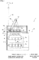
- Fig. 1 is a front elevation of a spinning winder. It is noted that, hereinafter, as shown in Fig. 1 , the leading end side of a later-described bobbin holder 7 will be referred to as a front side where an operator operates the spinning winder. As shown in Fig. 1 , the spinning winder 1 is arranged so that, to a winding unit 3 at a lower part, a plurality of yarns 10, which are continuously spun and supplied from a spinning machine 2 at an upper part while being aligned in the directions orthogonal to the plane of Fig. 1 (i.e., in the crosswise directions when viewed from the front side), are supplied by two godet rollers 11 and 12, and the yarns are wound by the winding unit 3.
- the winding unit 3 will be described first.
- the winding unit 3 is provided below the spinning machine 2 and forms a plurality of packages P by winding, onto respective bobbins B, a plurality of yarns 10 supplied from the spinning machine 2 via the two godet rollers 11 and 12.
- This winding unit 3 includes components such as a main body frame 5, a disc-shaped turret 6 attached to the main body frame 5 in a rotatable manner, two bobbin holders 7 (winding axes) each of which is supported by the turret 6 at one end and to each of which a plurality of bobbins B are attached in series along an axis 7a, a plurality of traverse guides 8 that are provided above the bobbins B attached to the bobbin holder 7 and traverse the yarns 10 that are to be wound onto the bobbins B, and a contact roller 9 which is arranged to be vertically movable with respect to the main body frame 5 so as to approach and move away from the bobbins B attached to the bobbin holder 7.
- the winding unit 3 winds the yarns 10 onto the rotating bobbins B, respectively, in such a way that the bobbin holder 7 is rotated by an unillustrated drive motor and therefore the bobbins B attached to this bobbin holder 7 are rotated.
- a yarn 10 is traversed in the axial directions of the bobbin B about a later-described fulcrum guide 13 by the traverse guide 8 which is arranged to be able to reciprocate in the axial directions of the bobbin B, with the result that a package P is formed.
- the contact roller 9 rotates while applying a predetermined contact pressure to the package P, so as to properly shape the package P.
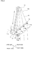
- Fig. 2 is a perspective view of the godet rollers and the fulcrum guides.
- the spinning winder 1 includes a frame 14 provided to be further from the viewer than the winding unit 3 in Fig. 1 , two godet rollers 11 and 12 that draw the yarns 10 supplied from the spinning machine 2, a plurality of fulcrum guides 13a to 13d (distribution guides) that distribute the yarns 10 threaded onto the godet roller 12 on the downstream to the respective bobbins B attached to the bobbin holder 7 of the winding unit 3 and function as the fulcrum of the traversal by the traverse guides 8, and a yarn threading guide 20 (yarn holding component) for threading the yarns 10 supplied from the godet roller 12 onto the fulcrum guides 13a to 13d.
- the two godet rollers 11 and 12 are rotatably supported by the frame 14 such that the axes 11a and 12a thereof are orthogonal to the axis 7a of the bobbin holder 7.
- These two godet rollers 11 and 12 are drive rollers driven by an unillustrated drive motor.
- the godet roller 11 is provided immediately below the spinning machine 2, whereas the godet roller 12 is provided above and behind the godet roller 11.
- the godet roller 12 is arranged to be movable, by an elevation mechanism 16 (see Fig. 1 ) such as a linear motor, between a yarn winding position (indicated by full lines in Figs. 1 and 2 ) above the substantial center of the fulcrum guides 13a to 13d in the alignment directions and a yarn threading position (indicated by two-dot chain lines in Figs. 1 and 2 ) which is below the yarn winding position and is in the vicinity of the yarn threading guide 20 which is close to the edge as compared to the fulcrum guides 13.
- an elevation mechanism 16 such as a linear motor
- the fulcrum guides 13a to 13d are aligned at the same intervals as the bobbins B along the axis 7a of each bobbin holder 7.
- the fulcrum guides 13a to 13d are provided below the downstream-side godet roller 12 at the yarn winding position, immediately above the traverse guides 8 and the bobbins B attached to the bobbin holder 7.
- each fulcrum guide 13 is fixedly supported by a supporting plate 15 attached to the frame 14, and an insertion slit 40 and a guide hole 41 are formed therein.
- the fulcrum guide 13 is arranged so that the yarn 10 sucked by an unillustrated suction pipe are threaded onto the guide hole 41 as the yarn Y is allowed to pass through the insertion slit 40 from behind.
- the yarns 10 supplied from the spinning machine 2 are fed downward and for a start wound onto the godet roller 11 while being aligned along the axis 11a. Thereafter, the yarns 10 wound onto the godet roller 11 diagonally run upward while being kept to be in parallel to each other and are then wound onto the godet roller 12 which is at the yarn winding position.
- the yarns 10 wound onto the godet roller 12 are threaded onto the fulcrum guides 13a to 13d, respectively, and then fed to the winding unit 3 below.
- the godet roller 12 is provided not side by side with the fulcrum guides 13a to 13d but above the fulcrum guides 13a to 13d, the bending angle of the yarn 10 at each fulcrum guide 13 is small, and hence the running speed of the yarn 10 can be increased.
- the yarn threading guide 20 is rod-shaped (or column-shaped) and extends in directions orthogonal to the alignment directions of the fulcrum guides 13a to 13d.
- grooves 20a are formed to correspond to the respective fulcrum guides 13a to 13d.
- the grooves 20a are formed at regular intervals in the length of the guide 20 and fully surround the guide 20.
- the yarn threading guide 20 is connected to a bar 23.
- the bar 23 is arranged to be movable in directions orthogonal to the alignment directions of the fulcrum guides 13a to 13d, with respect to a slidable component 21 which is slidable in the alignment directions of the fulcrum guides 13a to 13d. As the bar 23 moves, the yarn threading guide 20 moves in a direction orthogonal to the alignment directions of the fulcrum guides 13a to 13d.
- FIG. 4 An example of the mechanism of movement of the yarn threading guide 20 is shown in Fig. 4 .
- the bar 23 is biased by the spring 32 and is connected at its base end side to a cam follower 31 which is movable in the cam groove 30.
- the cam groove 30 is formed as a closed loop made up of a linear portion extending along the alignment directions of the fulcrum guides 13a to 13d and inclined portions inclined with respect to the linear portion.
- the yarn threading guide 20 moves in a direction along the alignment directions of the fulcrum guides 13a to 13d and moves, along the horizontal plane in parallel to the supporting plate 15, in an inclined direction across the fulcrum guides 13a to 13d.
- Fig. 4 illustrates the movement trace of the yarn threading guide at the time of yarn threading, and is a schematic plan view of the yarn threading guide and the fulcrum guide when viewed from the top.
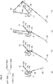
- Fig. 5 and Fig. 6 illustrate the yarn threading by the yarn threading guide.
- the yarn threading guide 20, the slidable component 21, and the bar 23 move in the order of (1) to (6), and the movement trace of each component is depicted at predetermined time intervals.
- the components are drawn in solid lines at the position (1) which is the origin, and are drawn in dashed lines at the subsequent positions (2) to (6).
- the yarn threading guide 20 is positioned at the origin ((1) in Fig. 4 ) which is in front of the foremost fulcrum guide 13d, and the godet roller 12 is moved to the yarn threading position. Thereafter, the yarns 10 supplied from the godet roller 12 are sucked and captured by the suction pipe 25.
- the operator operates the suction pipe 25 to thread the yarns 10 individually onto the respective grooves 20a of the yarn threading guide 20.
- the godet roller 12 is moved to the yarn threading position which is closer to the yarn threading guide 20 as compared to the yarn winding position, the yarns 10 are threaded onto the yarn threading guide 20 at the position close to the godet roller 12.
- the posture of the running yarn 10 is stable as compared to the posture of the yarn 10 at a position far from the godet roller 12, with the result that the yarn threading is easily done.
- the godet roller 12 is moved from the yarn threading position to the yarn winding position.
- the yarn threading guide 20 is moved in a direction A (see Fig. 4 ) along the guide rail 22 to the rearmost position (position (4) in Fig. 4 ) which is behind the rearmost fulcrum guide 13a.
- the yarns 10 threaded on the yarn threading guide 20 are moved to a position further behind the rearmost fulcrum guide 13a.
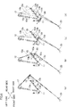
- the yarn threading guide 20 is moved along the alignment directions of the fulcrum guides 13a to 13d while the bar 23 is moved back, so that the yarns 10 are threaded onto the fulcrum guides 13a to 13d.
- the yarn threading guide 20 is moved from the rear side of the fulcrum guide 13a to the front side of the fulcrum guide 13d, along an inclined direction which forms an angle ⁇ with the alignment directions of the fulcrum guides 13a to 13d.
- the angle ⁇ is determined in accordance with the intervals 11 of the fulcrum guides 13a to 13d and the intervals 12 of the grooves 20a of the yarn threading guide 20.
- the yarns 10 are fed to the corresponding fulcrum guides 13 in such a way that the yarn threading guide 20 holding the yarns 10 is moved along the alignment directions of the fulcrum guides 13a to 13d between the fulcrum guides 13a to 13d and the bobbin holder 7, while the godet roller 12 and the fulcrum guides 13a to 13d are kept unmoved.
- the alignment directions of the yarns 10 held by the yarn threading guide 20 are orthogonal to the alignment directions of the fulcrum guides 13a to 13d, each fulcrum guide 13 allows a yarn to be threaded thereon from behind, and the yarn 10 enters the groove 20a of the yarn threading guide 20 in the same direction as in the yarn threading onto the fulcrum guide 13. For these reasons, as the yarn threading guide 20 is moved in the inclined direction from the rear side to the front side, the yarns held by the yarn threading guide 20 are serially passed to and threaded onto the fulcrum guides 13 without interfering with the supporting plate 15.
- the yarn threading guide 20 is small in size because it is simply required to hold yarns 10 and move, and the structure of the device including the yarn threading guide 20 and its moving mechanism is simplified. For this reason, the failure rate is decreased and the manufacturing cost is lowered. Furthermore, in regard to the retraction of the yarn threading guide 20 at the time of yarn winding onto the bobbin B, the area required for the retraction is small because the size of the guide 20 is small. Moreover, since the yarn threading guide 20 simply moves between the fulcrum guides 13a to 13d and the bobbin holder 7, it is unnecessary to take into account of the movable range of the yarn threading guide 20 as an additional space, and hence the design freedom is improved.
- the yarn threading guide 20 moves in the direction A along the alignment directions of the fulcrum guides 13a to 13d to position the yarns 10 to be behind the rearmost fulcrum guide 13a, and then moves in the inclined direction (direction B) so that the yarns are threaded onto the fulcrum guides 13a to 13d.
- the yarn threading guide 20 does not move in the inclined direction and moves only along the alignment directions of the fulcrum guides 13a to 13d.
- the yarns 10 held by the yarn threading guide 20 are moved to positions corresponding to the respective fulcrum guides 13a to 13d, as the yarn threading guide 20 is moved. Once the yarns 10 are fed to the corresponding fulcrum guides 13, the operator can conduct the yarn threading very easily.
- the godet roller 12 at the yarn winding position is above the fulcrum guides 13a to 13d
- the godet roller 12 may be provided on the front side or rear side of the fulcrum guides 13a to 13d in the alignment directions thereof.
- axis 12a of the godet roller 12 is orthogonal to the axis 7a of the bobbin holder 7, these axes may intersect with each other or may be in parallel to each other.
- fulcrum guide 13 functions not only as a fulcrum of traversal but also as a distribution guide for distributing yarns 10 to bobbins B, a fulcrum guide for traversal and a distribution guide may be independently provided.
Landscapes
- Spinning Methods And Devices For Manufacturing Artificial Fibers (AREA)
- Guides For Winding Or Rewinding, Or Guides For Filamentary Materials (AREA)
- Forwarding And Storing Of Filamentary Material (AREA)
Applications Claiming Priority (1)
| Application Number | Priority Date | Filing Date | Title |
|---|---|---|---|
| JP2011054215A JP5615743B2 (ja) | 2011-03-11 | 2011-03-11 | 紡糸巻取機 |
Publications (3)
| Publication Number | Publication Date |
|---|---|
| EP2497732A2 true EP2497732A2 (fr) | 2012-09-12 |
| EP2497732A3 EP2497732A3 (fr) | 2013-10-30 |
| EP2497732B1 EP2497732B1 (fr) | 2015-08-12 |
Family
ID=45811314
Family Applications (1)
| Application Number | Title | Priority Date | Filing Date |
|---|---|---|---|
| EP12157704.3A Active EP2497732B1 (fr) | 2011-03-11 | 2012-03-01 | Enrouleur de filature |
Country Status (3)
| Country | Link |
|---|---|
| EP (1) | EP2497732B1 (fr) |
| JP (1) | JP5615743B2 (fr) |
| CN (1) | CN102674075B (fr) |
Cited By (11)
| Publication number | Priority date | Publication date | Assignee | Title |
|---|---|---|---|---|
| CN105603547A (zh) * | 2016-02-25 | 2016-05-25 | 浙江昌隆化纤有限公司 | 一种纺丝高速卷绕机一步升头法 |
| CN105603552A (zh) * | 2016-02-25 | 2016-05-25 | 浙江昌隆化纤有限公司 | 一种纺丝高速卷绕机一步升头装置 |
| DE102015008621A1 (de) | 2015-07-02 | 2017-01-05 | Oerlikon Textile Gmbh & Co. Kg | Hilfsvorrichtung zum Anlegen eines Fadens |
| WO2018100142A1 (fr) * | 2016-12-02 | 2018-06-07 | Oerlikon Textile Gmbh & Co. Kg | Procédé et dispositif d'application d'une pluralité de fils synthétiques à une machine d'enroulage |
| DE102017000457A1 (de) | 2017-01-19 | 2018-07-19 | Oerlikon Textile Gmbh & Co. Kg | Aufspulmaschine |
| DE102017006689A1 (de) | 2017-07-14 | 2019-01-17 | Oerlikon Textile Gmbh & Co. Kg | Aufspulmaschine |
| EP3712097A1 (fr) * | 2019-03-18 | 2020-09-23 | TMT Machinery, Inc. | Machine textile et procédé d'enseignement |
| DE102020000286A1 (de) | 2020-01-18 | 2021-07-22 | Oerlikon Textile Gmbh & Co. Kg | Aufspulmaschine |
| DE102015202016B4 (de) | 2014-02-05 | 2022-12-15 | Tmt Machinery, Inc. | Garnwickeleinrichtung |
| DE102014220875B4 (de) | 2013-10-16 | 2022-12-29 | Tmt Machinery, Inc. | Wickelmaschine für gesponnenes Garn |
| EP4378868A1 (fr) * | 2022-11-30 | 2024-06-05 | TMT Machinery, Inc. | Enrouleur de fil |
Families Citing this family (9)
| Publication number | Priority date | Publication date | Assignee | Title |
|---|---|---|---|---|
| JP5711062B2 (ja) * | 2011-07-22 | 2015-04-30 | Tmtマシナリー株式会社 | 紡糸巻取機 |
| CN104828634B (zh) * | 2014-02-10 | 2019-04-30 | 日本Tmt机械株式会社 | 纺丝牵伸装置 |
| JP6681307B2 (ja) * | 2015-10-30 | 2020-04-15 | Tmtマシナリー株式会社 | 紡糸引取装置 |
| DE102017004193A1 (de) * | 2017-04-28 | 2018-10-31 | Oerlikon Textile Gmbh & Co. Kg | Verfahren und Vorrichtung zum Anlegen mehrerer gesponnener Fäden |
| JP7269783B2 (ja) * | 2018-06-11 | 2023-05-09 | Tmtマシナリー株式会社 | 紡糸巻取装置 |
| CN109763181B (zh) * | 2019-02-25 | 2023-09-22 | 张家港锦亿化纤有限公司 | 涤纶丝导丝器的挂丝装置 |
| JP7253431B2 (ja) | 2019-04-16 | 2023-04-06 | Tmtマシナリー株式会社 | 紡糸引取設備 |
| CN113529190A (zh) * | 2021-08-10 | 2021-10-22 | 北京中丽制机工程技术有限公司 | 一种新型纺丝卷绕装置及纺丝卷绕方法 |
| CN117822139B (zh) * | 2024-03-01 | 2024-07-09 | 常州市盛杰合力化纤有限公司 | 一种涤纶生产用长丝卷绕防断设备 |
Citations (1)
| Publication number | Priority date | Publication date | Assignee | Title |
|---|---|---|---|---|
| WO2008138827A2 (fr) | 2007-05-11 | 2008-11-20 | Oerlikon Textile Gmbh & Co. Kg | Dispositif de filage par fusion et de bobinage de fils synthétiques |
Family Cites Families (7)
| Publication number | Priority date | Publication date | Assignee | Title |
|---|---|---|---|---|
| IT1114634B (it) * | 1977-07-13 | 1986-01-27 | U T I T A Officine & Fonderie | Procedimento e dispositivo di selezione ed infilaggio per avvolgitrici di filati a piu' bobine |
| JP2535337B2 (ja) * | 1986-11-18 | 1996-09-18 | 東レ株式会社 | 糸掛方法および糸掛装置 |
| DE19719391A1 (de) * | 1996-05-10 | 1997-11-13 | Barmag Barmer Maschf | Fadenspule und Vorrichtung und Verfahren zu ihrer Herstellung |
| JP4176428B2 (ja) * | 2002-09-17 | 2008-11-05 | Tstm株式会社 | 綾振り装置 |
| DE102007014511A1 (de) * | 2007-03-27 | 2008-10-02 | Saurer Gmbh & Co. Kg | Verfahren und Vorrichtung zum Schmelzspinnen, Behandeln und Aufwickeln mehrerer multifiler Fäden |
| DE102009013974A1 (de) * | 2009-03-19 | 2010-09-23 | Oerlikon Textile Gmbh & Co. Kg | Vorrichtung zum Schmelzspinnen und Aufwickeln mehrerer Fäden |
| DE112009005461A5 (de) * | 2009-04-29 | 2012-10-31 | Oerlikon Textile Gmbh & Co. Kg | Aufspulmaschine |
-
2011
- 2011-03-11 JP JP2011054215A patent/JP5615743B2/ja active Active
-
2012
- 2012-03-01 EP EP12157704.3A patent/EP2497732B1/fr active Active
- 2012-03-07 CN CN201210058494.XA patent/CN102674075B/zh active Active
Patent Citations (1)
| Publication number | Priority date | Publication date | Assignee | Title |
|---|---|---|---|---|
| WO2008138827A2 (fr) | 2007-05-11 | 2008-11-20 | Oerlikon Textile Gmbh & Co. Kg | Dispositif de filage par fusion et de bobinage de fils synthétiques |
Cited By (17)
| Publication number | Priority date | Publication date | Assignee | Title |
|---|---|---|---|---|
| DE102014220875B4 (de) | 2013-10-16 | 2022-12-29 | Tmt Machinery, Inc. | Wickelmaschine für gesponnenes Garn |
| DE102015202016B4 (de) | 2014-02-05 | 2022-12-15 | Tmt Machinery, Inc. | Garnwickeleinrichtung |
| DE102015008621A1 (de) | 2015-07-02 | 2017-01-05 | Oerlikon Textile Gmbh & Co. Kg | Hilfsvorrichtung zum Anlegen eines Fadens |
| WO2017001659A1 (fr) * | 2015-07-02 | 2017-01-05 | Oerlikon Textile Gmbh & Co. Kg | Dispositif auxiliaire d'application d'un fil |
| CN105603552A (zh) * | 2016-02-25 | 2016-05-25 | 浙江昌隆化纤有限公司 | 一种纺丝高速卷绕机一步升头装置 |
| CN105603547A (zh) * | 2016-02-25 | 2016-05-25 | 浙江昌隆化纤有限公司 | 一种纺丝高速卷绕机一步升头法 |
| WO2018100142A1 (fr) * | 2016-12-02 | 2018-06-07 | Oerlikon Textile Gmbh & Co. Kg | Procédé et dispositif d'application d'une pluralité de fils synthétiques à une machine d'enroulage |
| CN110267894B (zh) * | 2017-01-19 | 2021-03-09 | 欧瑞康纺织有限及两合公司 | 卷绕机 |
| DE102017000457A1 (de) | 2017-01-19 | 2018-07-19 | Oerlikon Textile Gmbh & Co. Kg | Aufspulmaschine |
| WO2018134048A1 (fr) | 2017-01-19 | 2018-07-26 | Oerlikon Textile Gmbh & Co. Kg | Bobineuse |
| CN110267894A (zh) * | 2017-01-19 | 2019-09-20 | 欧瑞康纺织有限及两合公司 | 卷绕机 |
| WO2019011983A1 (fr) | 2017-07-14 | 2019-01-17 | Oerlikon Textile Gmbh & Co. Kg | Bobineuse |
| DE102017006689A1 (de) | 2017-07-14 | 2019-01-17 | Oerlikon Textile Gmbh & Co. Kg | Aufspulmaschine |
| EP3712097A1 (fr) * | 2019-03-18 | 2020-09-23 | TMT Machinery, Inc. | Machine textile et procédé d'enseignement |
| DE102020000286A1 (de) | 2020-01-18 | 2021-07-22 | Oerlikon Textile Gmbh & Co. Kg | Aufspulmaschine |
| WO2021144300A1 (fr) | 2020-01-18 | 2021-07-22 | Oerlikon Textile Gmbh & Co. Kg | Bobinoir |
| EP4378868A1 (fr) * | 2022-11-30 | 2024-06-05 | TMT Machinery, Inc. | Enrouleur de fil |
Also Published As
| Publication number | Publication date |
|---|---|
| CN102674075B (zh) | 2016-04-20 |
| EP2497732A3 (fr) | 2013-10-30 |
| JP5615743B2 (ja) | 2014-10-29 |
| CN102674075A (zh) | 2012-09-19 |
| EP2497732B1 (fr) | 2015-08-12 |
| JP2012188784A (ja) | 2012-10-04 |
Similar Documents
| Publication | Publication Date | Title |
|---|---|---|
| EP2497732B1 (fr) | Enrouleur de filature | |
| CN106917149B (zh) | 自动挂丝装置 | |
| EP2636625A2 (fr) | Appareil de rattrapage de fil fin | |
| EP2505538B1 (fr) | Enrouleur de filature | |
| EP2186765B1 (fr) | Enrouleur récepteur | |
| CN110869302B (zh) | 卷绕机 | |
| JP2015078455A (ja) | 紡糸巻取機 | |
| US10954098B2 (en) | Yarn delivery device for a twisting or cabling machine | |
| JP2015165060A (ja) | 紡糸引取装置 | |
| JP5398462B2 (ja) | 糸搬送装置 | |
| US8152090B2 (en) | Take-up device | |
| JP2008297078A (ja) | 糸条巻取機 | |
| EP2548830A3 (fr) | Enrouleur de filature | |
| JP7014804B2 (ja) | 巻取り機 | |
| EP1995201A2 (fr) | Renvideur de fil | |
| EP3184475A1 (fr) | Dispositif de bobinage de fil, élément d'enfilage de fil et procédé d'enfilage des fils dans dispositif de bobinage de fil | |
| US9365388B2 (en) | Apparatus for continuously winding up a thread | |
| JP7130365B2 (ja) | クロス捲きパッケージを生産する繊維機械のワークステーションにおける綾振り三角形領域に配置された機械式糸貯留装置用糸ガイドプーリー | |
| EP1616829B1 (fr) | Guide-fil de bobineur automatique de type rotatif | |
| JP6461705B2 (ja) | 糸切断装置 | |
| CN107130308B (zh) | 纺丝牵引机 | |
| KR20230133192A (ko) | 실 권취기 | |
| KR101623334B1 (ko) | 원사의 권취장치 |
Legal Events
| Date | Code | Title | Description |
|---|---|---|---|
| PUAI | Public reference made under article 153(3) epc to a published international application that has entered the european phase |
Free format text: ORIGINAL CODE: 0009012 |
|
| AK | Designated contracting states |
Kind code of ref document: A2 Designated state(s): AL AT BE BG CH CY CZ DE DK EE ES FI FR GB GR HR HU IE IS IT LI LT LU LV MC MK MT NL NO PL PT RO RS SE SI SK SM TR |
|
| AX | Request for extension of the european patent |
Extension state: BA ME |
|
| PUAL | Search report despatched |
Free format text: ORIGINAL CODE: 0009013 |
|
| AK | Designated contracting states |
Kind code of ref document: A3 Designated state(s): AL AT BE BG CH CY CZ DE DK EE ES FI FR GB GR HR HU IE IS IT LI LT LU LV MC MK MT NL NO PL PT RO RS SE SI SK SM TR |
|
| AX | Request for extension of the european patent |
Extension state: BA ME |
|
| RIC1 | Information provided on ipc code assigned before grant |
Ipc: B65H 57/28 20060101ALI20130920BHEP Ipc: B65H 57/00 20060101ALI20130920BHEP Ipc: B65H 51/06 20060101AFI20130920BHEP Ipc: B65H 57/16 20060101ALI20130920BHEP Ipc: B65H 67/048 20060101ALI20130920BHEP |
|
| 17P | Request for examination filed |
Effective date: 20131227 |
|
| RBV | Designated contracting states (corrected) |
Designated state(s): AL AT BE BG CH CY CZ DE DK EE ES FI FR GB GR HR HU IE IS IT LI LT LU LV MC MK MT NL NO PL PT RO RS SE SI SK SM TR |
|
| 17Q | First examination report despatched |
Effective date: 20140923 |
|
| GRAP | Despatch of communication of intention to grant a patent |
Free format text: ORIGINAL CODE: EPIDOSNIGR1 |
|
| INTG | Intention to grant announced |
Effective date: 20150325 |
|
| GRAS | Grant fee paid |
Free format text: ORIGINAL CODE: EPIDOSNIGR3 |
|
| GRAA | (expected) grant |
Free format text: ORIGINAL CODE: 0009210 |
|
| AK | Designated contracting states |
Kind code of ref document: B1 Designated state(s): AL AT BE BG CH CY CZ DE DK EE ES FI FR GB GR HR HU IE IS IT LI LT LU LV MC MK MT NL NO PL PT RO RS SE SI SK SM TR |
|
| REG | Reference to a national code |
Ref country code: GB Ref legal event code: FG4D |
|
| REG | Reference to a national code |
Ref country code: CH Ref legal event code: EP |
|
| REG | Reference to a national code |
Ref country code: AT Ref legal event code: REF Ref document number: 741951 Country of ref document: AT Kind code of ref document: T Effective date: 20150815 |
|
| REG | Reference to a national code |
Ref country code: IE Ref legal event code: FG4D |
|
| REG | Reference to a national code |
Ref country code: DE Ref legal event code: R096 Ref document number: 602012009435 Country of ref document: DE |
|
| REG | Reference to a national code |
Ref country code: LT Ref legal event code: MG4D |
|
| REG | Reference to a national code |
Ref country code: AT Ref legal event code: MK05 Ref document number: 741951 Country of ref document: AT Kind code of ref document: T Effective date: 20150812 |
|
| REG | Reference to a national code |
Ref country code: NL Ref legal event code: MP Effective date: 20150812 |
|
| PG25 | Lapsed in a contracting state [announced via postgrant information from national office to epo] |
Ref country code: LV Free format text: LAPSE BECAUSE OF FAILURE TO SUBMIT A TRANSLATION OF THE DESCRIPTION OR TO PAY THE FEE WITHIN THE PRESCRIBED TIME-LIMIT Effective date: 20150812 Ref country code: LT Free format text: LAPSE BECAUSE OF FAILURE TO SUBMIT A TRANSLATION OF THE DESCRIPTION OR TO PAY THE FEE WITHIN THE PRESCRIBED TIME-LIMIT Effective date: 20150812 Ref country code: GR Free format text: LAPSE BECAUSE OF FAILURE TO SUBMIT A TRANSLATION OF THE DESCRIPTION OR TO PAY THE FEE WITHIN THE PRESCRIBED TIME-LIMIT Effective date: 20151113 Ref country code: FI Free format text: LAPSE BECAUSE OF FAILURE TO SUBMIT A TRANSLATION OF THE DESCRIPTION OR TO PAY THE FEE WITHIN THE PRESCRIBED TIME-LIMIT Effective date: 20150812 Ref country code: NO Free format text: LAPSE BECAUSE OF FAILURE TO SUBMIT A TRANSLATION OF THE DESCRIPTION OR TO PAY THE FEE WITHIN THE PRESCRIBED TIME-LIMIT Effective date: 20151112 |
|
| PG25 | Lapsed in a contracting state [announced via postgrant information from national office to epo] |
Ref country code: PT Free format text: LAPSE BECAUSE OF FAILURE TO SUBMIT A TRANSLATION OF THE DESCRIPTION OR TO PAY THE FEE WITHIN THE PRESCRIBED TIME-LIMIT Effective date: 20151214 Ref country code: AT Free format text: LAPSE BECAUSE OF FAILURE TO SUBMIT A TRANSLATION OF THE DESCRIPTION OR TO PAY THE FEE WITHIN THE PRESCRIBED TIME-LIMIT Effective date: 20150812 Ref country code: HR Free format text: LAPSE BECAUSE OF FAILURE TO SUBMIT A TRANSLATION OF THE DESCRIPTION OR TO PAY THE FEE WITHIN THE PRESCRIBED TIME-LIMIT Effective date: 20150812 Ref country code: IS Free format text: LAPSE BECAUSE OF FAILURE TO SUBMIT A TRANSLATION OF THE DESCRIPTION OR TO PAY THE FEE WITHIN THE PRESCRIBED TIME-LIMIT Effective date: 20151212 Ref country code: ES Free format text: LAPSE BECAUSE OF FAILURE TO SUBMIT A TRANSLATION OF THE DESCRIPTION OR TO PAY THE FEE WITHIN THE PRESCRIBED TIME-LIMIT Effective date: 20150812 Ref country code: SE Free format text: LAPSE BECAUSE OF FAILURE TO SUBMIT A TRANSLATION OF THE DESCRIPTION OR TO PAY THE FEE WITHIN THE PRESCRIBED TIME-LIMIT Effective date: 20150812 Ref country code: RS Free format text: LAPSE BECAUSE OF FAILURE TO SUBMIT A TRANSLATION OF THE DESCRIPTION OR TO PAY THE FEE WITHIN THE PRESCRIBED TIME-LIMIT Effective date: 20150812 Ref country code: PL Free format text: LAPSE BECAUSE OF FAILURE TO SUBMIT A TRANSLATION OF THE DESCRIPTION OR TO PAY THE FEE WITHIN THE PRESCRIBED TIME-LIMIT Effective date: 20150812 |
|
| PG25 | Lapsed in a contracting state [announced via postgrant information from national office to epo] |
Ref country code: NL Free format text: LAPSE BECAUSE OF FAILURE TO SUBMIT A TRANSLATION OF THE DESCRIPTION OR TO PAY THE FEE WITHIN THE PRESCRIBED TIME-LIMIT Effective date: 20150812 |
|
| PG25 | Lapsed in a contracting state [announced via postgrant information from national office to epo] |
Ref country code: IT Free format text: LAPSE BECAUSE OF FAILURE TO SUBMIT A TRANSLATION OF THE DESCRIPTION OR TO PAY THE FEE WITHIN THE PRESCRIBED TIME-LIMIT Effective date: 20150812 Ref country code: DK Free format text: LAPSE BECAUSE OF FAILURE TO SUBMIT A TRANSLATION OF THE DESCRIPTION OR TO PAY THE FEE WITHIN THE PRESCRIBED TIME-LIMIT Effective date: 20150812 Ref country code: EE Free format text: LAPSE BECAUSE OF FAILURE TO SUBMIT A TRANSLATION OF THE DESCRIPTION OR TO PAY THE FEE WITHIN THE PRESCRIBED TIME-LIMIT Effective date: 20150812 Ref country code: CZ Free format text: LAPSE BECAUSE OF FAILURE TO SUBMIT A TRANSLATION OF THE DESCRIPTION OR TO PAY THE FEE WITHIN THE PRESCRIBED TIME-LIMIT Effective date: 20150812 Ref country code: SK Free format text: LAPSE BECAUSE OF FAILURE TO SUBMIT A TRANSLATION OF THE DESCRIPTION OR TO PAY THE FEE WITHIN THE PRESCRIBED TIME-LIMIT Effective date: 20150812 |
|
| REG | Reference to a national code |
Ref country code: DE Ref legal event code: R097 Ref document number: 602012009435 Country of ref document: DE |
|
| PG25 | Lapsed in a contracting state [announced via postgrant information from national office to epo] |
Ref country code: RO Free format text: LAPSE BECAUSE OF FAILURE TO SUBMIT A TRANSLATION OF THE DESCRIPTION OR TO PAY THE FEE WITHIN THE PRESCRIBED TIME-LIMIT Effective date: 20150812 |
|
| PLBE | No opposition filed within time limit |
Free format text: ORIGINAL CODE: 0009261 |
|
| STAA | Information on the status of an ep patent application or granted ep patent |
Free format text: STATUS: NO OPPOSITION FILED WITHIN TIME LIMIT |
|
| 26N | No opposition filed |
Effective date: 20160513 |
|
| PG25 | Lapsed in a contracting state [announced via postgrant information from national office to epo] |
Ref country code: BE Free format text: LAPSE BECAUSE OF NON-PAYMENT OF DUE FEES Effective date: 20160331 Ref country code: SI Free format text: LAPSE BECAUSE OF FAILURE TO SUBMIT A TRANSLATION OF THE DESCRIPTION OR TO PAY THE FEE WITHIN THE PRESCRIBED TIME-LIMIT Effective date: 20150812 |
|
| PG25 | Lapsed in a contracting state [announced via postgrant information from national office to epo] |
Ref country code: LU Free format text: LAPSE BECAUSE OF FAILURE TO SUBMIT A TRANSLATION OF THE DESCRIPTION OR TO PAY THE FEE WITHIN THE PRESCRIBED TIME-LIMIT Effective date: 20160301 Ref country code: MC Free format text: LAPSE BECAUSE OF FAILURE TO SUBMIT A TRANSLATION OF THE DESCRIPTION OR TO PAY THE FEE WITHIN THE PRESCRIBED TIME-LIMIT Effective date: 20150812 |
|
| REG | Reference to a national code |
Ref country code: CH Ref legal event code: PL |
|
| GBPC | Gb: european patent ceased through non-payment of renewal fee |
Effective date: 20160301 |
|
| REG | Reference to a national code |
Ref country code: IE Ref legal event code: MM4A |
|
| PG25 | Lapsed in a contracting state [announced via postgrant information from national office to epo] |
Ref country code: BE Free format text: LAPSE BECAUSE OF FAILURE TO SUBMIT A TRANSLATION OF THE DESCRIPTION OR TO PAY THE FEE WITHIN THE PRESCRIBED TIME-LIMIT Effective date: 20150812 |
|
| REG | Reference to a national code |
Ref country code: FR Ref legal event code: ST Effective date: 20161130 |
|
| PG25 | Lapsed in a contracting state [announced via postgrant information from national office to epo] |
Ref country code: LI Free format text: LAPSE BECAUSE OF NON-PAYMENT OF DUE FEES Effective date: 20160331 Ref country code: FR Free format text: LAPSE BECAUSE OF NON-PAYMENT OF DUE FEES Effective date: 20160331 Ref country code: CH Free format text: LAPSE BECAUSE OF NON-PAYMENT OF DUE FEES Effective date: 20160331 Ref country code: IE Free format text: LAPSE BECAUSE OF NON-PAYMENT OF DUE FEES Effective date: 20160301 Ref country code: GB Free format text: LAPSE BECAUSE OF NON-PAYMENT OF DUE FEES Effective date: 20160301 |
|
| PG25 | Lapsed in a contracting state [announced via postgrant information from national office to epo] |
Ref country code: MT Free format text: LAPSE BECAUSE OF FAILURE TO SUBMIT A TRANSLATION OF THE DESCRIPTION OR TO PAY THE FEE WITHIN THE PRESCRIBED TIME-LIMIT Effective date: 20150812 |
|
| PG25 | Lapsed in a contracting state [announced via postgrant information from national office to epo] |
Ref country code: HU Free format text: LAPSE BECAUSE OF FAILURE TO SUBMIT A TRANSLATION OF THE DESCRIPTION OR TO PAY THE FEE WITHIN THE PRESCRIBED TIME-LIMIT; INVALID AB INITIO Effective date: 20120301 Ref country code: CY Free format text: LAPSE BECAUSE OF FAILURE TO SUBMIT A TRANSLATION OF THE DESCRIPTION OR TO PAY THE FEE WITHIN THE PRESCRIBED TIME-LIMIT Effective date: 20150812 Ref country code: SM Free format text: LAPSE BECAUSE OF FAILURE TO SUBMIT A TRANSLATION OF THE DESCRIPTION OR TO PAY THE FEE WITHIN THE PRESCRIBED TIME-LIMIT Effective date: 20150812 |
|
| PG25 | Lapsed in a contracting state [announced via postgrant information from national office to epo] |
Ref country code: TR Free format text: LAPSE BECAUSE OF FAILURE TO SUBMIT A TRANSLATION OF THE DESCRIPTION OR TO PAY THE FEE WITHIN THE PRESCRIBED TIME-LIMIT Effective date: 20150812 Ref country code: MK Free format text: LAPSE BECAUSE OF FAILURE TO SUBMIT A TRANSLATION OF THE DESCRIPTION OR TO PAY THE FEE WITHIN THE PRESCRIBED TIME-LIMIT Effective date: 20150812 Ref country code: MT Free format text: LAPSE BECAUSE OF FAILURE TO SUBMIT A TRANSLATION OF THE DESCRIPTION OR TO PAY THE FEE WITHIN THE PRESCRIBED TIME-LIMIT Effective date: 20160331 |
|
| PG25 | Lapsed in a contracting state [announced via postgrant information from national office to epo] |
Ref country code: BG Free format text: LAPSE BECAUSE OF FAILURE TO SUBMIT A TRANSLATION OF THE DESCRIPTION OR TO PAY THE FEE WITHIN THE PRESCRIBED TIME-LIMIT Effective date: 20150812 |
|
| PG25 | Lapsed in a contracting state [announced via postgrant information from national office to epo] |
Ref country code: AL Free format text: LAPSE BECAUSE OF FAILURE TO SUBMIT A TRANSLATION OF THE DESCRIPTION OR TO PAY THE FEE WITHIN THE PRESCRIBED TIME-LIMIT Effective date: 20150812 |
|
| P01 | Opt-out of the competence of the unified patent court (upc) registered |
Effective date: 20230426 |
|
| PGFP | Annual fee paid to national office [announced via postgrant information from national office to epo] |
Ref country code: DE Payment date: 20240320 Year of fee payment: 13 |