EP2495079B1 - Slip detection apparatus and method for a mobile robot - Google Patents
Slip detection apparatus and method for a mobile robot Download PDFInfo
- Publication number
- EP2495079B1 EP2495079B1 EP09850898.9A EP09850898A EP2495079B1 EP 2495079 B1 EP2495079 B1 EP 2495079B1 EP 09850898 A EP09850898 A EP 09850898A EP 2495079 B1 EP2495079 B1 EP 2495079B1
- Authority
- EP
- European Patent Office
- Prior art keywords
- slip
- mobile robot
- angle
- detecting
- image
- Prior art date
- Legal status (The legal status is an assumption and is not a legal conclusion. Google has not performed a legal analysis and makes no representation as to the accuracy of the status listed.)
- Not-in-force
Links
- 238000000034 method Methods 0.000 title claims description 46
- 238000001514 detection method Methods 0.000 title description 2
- 238000011084 recovery Methods 0.000 claims description 2
- 238000010586 diagram Methods 0.000 description 14
- 230000008569 process Effects 0.000 description 9
- 238000004140 cleaning Methods 0.000 description 5
- 238000012986 modification Methods 0.000 description 5
- 230000004048 modification Effects 0.000 description 5
- 238000012545 processing Methods 0.000 description 5
- 230000008859 change Effects 0.000 description 2
- 238000010276 construction Methods 0.000 description 2
- 238000005286 illumination Methods 0.000 description 2
- 230000004807 localization Effects 0.000 description 2
- 238000007781 pre-processing Methods 0.000 description 2
- 238000005070 sampling Methods 0.000 description 2
- 230000000007 visual effect Effects 0.000 description 2
- 230000000295 complement effect Effects 0.000 description 1
- 238000010924 continuous production Methods 0.000 description 1
- 238000012937 correction Methods 0.000 description 1
- 230000000694 effects Effects 0.000 description 1
- 238000005516 engineering process Methods 0.000 description 1
- 239000000284 extract Substances 0.000 description 1
- 238000013507 mapping Methods 0.000 description 1
- 238000005259 measurement Methods 0.000 description 1
- 230000007246 mechanism Effects 0.000 description 1
- 229910044991 metal oxide Inorganic materials 0.000 description 1
- 150000004706 metal oxides Chemical class 0.000 description 1
- 239000004065 semiconductor Substances 0.000 description 1
- 238000010407 vacuum cleaning Methods 0.000 description 1
Images


Classifications
-
- B—PERFORMING OPERATIONS; TRANSPORTING
- B25—HAND TOOLS; PORTABLE POWER-DRIVEN TOOLS; MANIPULATORS
- B25J—MANIPULATORS; CHAMBERS PROVIDED WITH MANIPULATION DEVICES
- B25J13/00—Controls for manipulators
- B25J13/08—Controls for manipulators by means of sensing devices, e.g. viewing or touching devices
-
- B—PERFORMING OPERATIONS; TRANSPORTING
- B25—HAND TOOLS; PORTABLE POWER-DRIVEN TOOLS; MANIPULATORS
- B25J—MANIPULATORS; CHAMBERS PROVIDED WITH MANIPULATION DEVICES
- B25J9/00—Programme-controlled manipulators
- B25J9/16—Programme controls
- B25J9/1694—Programme controls characterised by use of sensors other than normal servo-feedback from position, speed or acceleration sensors, perception control, multi-sensor controlled systems, sensor fusion
- B25J9/1697—Vision controlled systems
-
- B—PERFORMING OPERATIONS; TRANSPORTING
- B25—HAND TOOLS; PORTABLE POWER-DRIVEN TOOLS; MANIPULATORS
- B25J—MANIPULATORS; CHAMBERS PROVIDED WITH MANIPULATION DEVICES
- B25J19/00—Accessories fitted to manipulators, e.g. for monitoring, for viewing; Safety devices combined with or specially adapted for use in connection with manipulators
- B25J19/02—Sensing devices
-
- B—PERFORMING OPERATIONS; TRANSPORTING
- B25—HAND TOOLS; PORTABLE POWER-DRIVEN TOOLS; MANIPULATORS
- B25J—MANIPULATORS; CHAMBERS PROVIDED WITH MANIPULATION DEVICES
- B25J9/00—Programme-controlled manipulators
- B25J9/16—Programme controls
- B25J9/1615—Programme controls characterised by special kind of manipulator, e.g. planar, scara, gantry, cantilever, space, closed chain, passive/active joints and tendon driven manipulators
- B25J9/162—Mobile manipulator, movable base with manipulator arm mounted on it
-
- G—PHYSICS
- G05—CONTROLLING; REGULATING
- G05D—SYSTEMS FOR CONTROLLING OR REGULATING NON-ELECTRIC VARIABLES
- G05D1/00—Control of position, course or altitude of land, water, air, or space vehicles, e.g. automatic pilot
- G05D1/02—Control of position or course in two dimensions
- G05D1/021—Control of position or course in two dimensions specially adapted to land vehicles
- G05D1/0231—Control of position or course in two dimensions specially adapted to land vehicles using optical position detecting means
- G05D1/0246—Control of position or course in two dimensions specially adapted to land vehicles using optical position detecting means using a video camera in combination with image processing means
- G05D1/0253—Control of position or course in two dimensions specially adapted to land vehicles using optical position detecting means using a video camera in combination with image processing means extracting relative motion information from a plurality of images taken successively, e.g. visual odometry, optical flow
-
- G—PHYSICS
- G05—CONTROLLING; REGULATING
- G05D—SYSTEMS FOR CONTROLLING OR REGULATING NON-ELECTRIC VARIABLES
- G05D1/00—Control of position, course or altitude of land, water, air, or space vehicles, e.g. automatic pilot
- G05D1/02—Control of position or course in two dimensions
- G05D1/021—Control of position or course in two dimensions specially adapted to land vehicles
- G05D1/0268—Control of position or course in two dimensions specially adapted to land vehicles using internal positioning means
- G05D1/0272—Control of position or course in two dimensions specially adapted to land vehicles using internal positioning means comprising means for registering the travel distance, e.g. revolutions of wheels
-
- Y—GENERAL TAGGING OF NEW TECHNOLOGICAL DEVELOPMENTS; GENERAL TAGGING OF CROSS-SECTIONAL TECHNOLOGIES SPANNING OVER SEVERAL SECTIONS OF THE IPC; TECHNICAL SUBJECTS COVERED BY FORMER USPC CROSS-REFERENCE ART COLLECTIONS [XRACs] AND DIGESTS
- Y10—TECHNICAL SUBJECTS COVERED BY FORMER USPC
- Y10S—TECHNICAL SUBJECTS COVERED BY FORMER USPC CROSS-REFERENCE ART COLLECTIONS [XRACs] AND DIGESTS
- Y10S901/00—Robots
- Y10S901/01—Mobile robot
Definitions
- the present invention relates to an apparatus and a method for detecting slips of a mobile robot. More specifically, the present invention relates to an apparatus and a method for detecting slips of a mobile robot capable of accurately detecting slips generated during a heading of a mobile robot by using a plurality of direction sensors and a single image sensor, controlling the heading of the mobile robot based on the detected slips so as to escape a danger zone, and recovering a location of the mobile robot that is falsely recognized due to the slip.
- a representative example of the mobile robot may include a cleaning robot cleaning the inside of a house or a building, a guide robot guiding location, and the like.
- the cleaning robot cleans an indoor floor using a vacuum cleaning unit provided therein while moving including various sensors and heading units.
- various types of cleaning robots have been commercialized.
- SLAM simultaneous localization and mapping
- an image based SLAM builds a map for the surrounding environment using visual features extracted from an image and estimates a posture of robot.
- the mobile robot is headed based on dead reckoning by using a gyroscope and an encoder provided in a driving motor and analyzes an image using a camera mounted at a top thereof and build a map.
- an accumulated error is corrected by using image information acquired from the camera.
- US 2009/149994 A1 discloses a method and an apparatus for correcting a pose of a moving robot.
- the method includes sensing an entrance using a distance-sensing sensor mounted on the moving robot, storing first distance data of the sensed entrance, after the moving robot travels, newly sensing the entrance using the distance-sensing sensor, and correcting the pose of the moving robot using the first distance data and second distance data corresponding to the entrance newly sensed after the moving robot travels.
- the self-localization of the robot is done with a model-based vision system, and a non-stop navigation is realized by a retroactive position correction system.
- Stationary obstacles are avoided with single-camera vision and moving obstacles are detected with ultrasonic sensors.
- the mobile robot according to the related art as described above does not effectively escape the slip region or accurately detect a slip angle and a direction when the slips are generated during the heading of the mobile robot.
- the present invention has been made in an effort to provide an apparatus and a method for detecting slips of a mobile robot capable of detecting a slip angle and a slip direction at the time of a side slip, determining a type of slips by detecting a front slip, escaping a slip region by different methods according to a type of slips, and recovering an accumulated error by estimating the generated slip direction and time.
- An exemplary embodiment of the present invention provides an apparatus for detecting slips of a mobile robot, including: a first rotation angle estimating unit that estimates a first rotation angle estimated that the mobile robot rotates; a second rotation angle measuring unit that measures a second rotation angle generated by an actual rotation of the mobile robot; an image variation calculating unit that calculates variations of at least two sequential images acquired from an image acquisition unit; and a slip detecting unit that detects a type of slips by calculating a slip direction and a slip angle of the mobile robot based on an error angle of the first and second rotation angles and the image variations and outputs different escape control signals for allowing the mobile robot to escape a slip region according to the type of detected slips, wherein the slip detecting unit compares the image variations with reference variations to estimate that the mobile robot is congested when the image variations are smaller than the reference variations, thereby calculating a congested frequency.
- the slip detecting unit may output a recovery signal of a location of the mobile robot for the error of location information at the time of the slip generation based on the slip direction, the slip angle, and the image variations.
- the slip detecting unit may detect a generation of a first slip in the mobile robot when the error angle is larger than a reference error angle.
- the slip detecting unit may determine that a slip is generated at a right wheel of the mobile robot when a sign of the error angle has a negative value at the time of detecting the slip and output an escape control signal that allows the mobile robot to move backward by a predetermined distance or for a predetermined time and then, move forward in a left direction.
- the slip detecting unit may determine that a slip is generated at a left wheel of the mobile robot when a sign of the error angle has a positive value at the time of detecting the slip and output an escape control signal that allows the mobile robot to move backward by a predetermined distance or for a predetermined time and then, move forward in a right direction.
- the slip detecting unit may detect a generation of a second slip when the congested frequency is larger than a reference frequency and a speed of the mobile robot based on the error angle is larger than a reference speed.
- Another exemplary embodiment of the present invention provides a method for detecting slips of a mobile robot, including: a) estimating a first rotation angle estimated that the mobile robot rotates; b) measuring a second rotation angle generated by an actual rotation of the mobile robot; c) detecting a first slip by obtaining an error angle of the first rotation angle and the second rotation angle and calculating a slip direction and a slip angle of the mobile robot based on the error angle and d) detecting a second slip by calculating variations of at least two sequentially input images, wherein the detecting of the second slip includes: dividing the input image into N regions and increasing an object region by 1/N based on a heading direction or an opposite direction of the mobile robot to calculate an average and a variance of each increased region; and estimating that the input image is congested to calculate a congested frequency when the image variations is smaller than reference variations if it is determined that the image is not shielded based on the variations of the average and variance values of each region.
- the method may further include: e) detecting a type of slips based on the detected first slip and second slip and selectively escaping a slip region according to the type of detected slips.
- the method may further include: f) recovering a location of the mobile robot based on the slip direction, the slip angle, and the image variations.
- the estimating of the first rotation angle may include: detecting a first angular velocity that is a rotation speed of a left wheel driving unit of the mobile robot and a second angular velocity that is a rotation speed of a right wheel driving unit; and calculating the first rotation angle based on a difference between the first angular velocity and the second angular velocity and a diameter of a wheel of the mobile robot.
- the detecting of the first slip may include: obtaining an error angle between the first rotation angle and the second rotation angle and comparing the error angle with a reference error angle; and determining that a slip is generated in the mobile robot when the error angle is larger than the reference error angle to allow the mobile robot to escape the slip region.
- the mobile robot may move backward by a predetermined distance or for a predetermined time and then, move forward in a direction opposite to the slip direction so as to escape the slip region.
- the mobile robot may move backward by a predetermined distance or for a predetermined time and then, move forward in a left direction so as to escape the slip region by determining that a slip is generated at a right wheel of the mobile robot when a sign of the error angle has a negative value.
- the mobile robot may move backward by a predetermined distance or for a predetermined time and then, move forward in a right direction so as to escape the slip region by determining that a slip is generated at a left wheel of the mobile robot when a sign of the error angle has a positive value.
- the error angle may have a value between +180° and - 180° based on an initial position of the mobile robot.
- an error angle of the discontinuous period may move in a y-axis direction in parallel to pre-process the error angle so that the discontinuous period is a continuous period.
- the generation of the second slip may be detected.
- the generation of the second slip may be detected, the mobile robot may move backward by a predetermined distance or for a predetermined time and then, may be headed while avoiding the slip generation region.
- the apparatus and the method for detecting slips of a mobile robot can detect a type of slips by detecting the slip angle and the slip direction at the time of the side slip and detecting the front slip.
- the apparatus and the method for detecting slips of a mobile robot according to the exemplary embodiment of the present invention can effectively escape the slip region by different methods according to a type o detected slip.
- the apparatus and the method for detecting slips of a mobile robot can recover the accumulated location error of the mobile robot at the time of the slip generation by estimating the slip direction and time.
- FIG. 1 is a diagram showing a configuration of a mobile robot to which an exemplary embodiment of the present invention is applied.
- a mobile robot 100 may be configured to include an image acquisition unit 110 that acquires an image, an image processing unit 120 that process the image acquired by the image acquisition unit 110, extracts features from the image, and generates descriptors for the features, a sensor unit 140 that detects moving orientation information, a moving distance, and the like, of the mobile robot 100, a main control unit 130 that builds a map for a space in which the mobile robot moves based on the acquired image and controls an operation of the mobile robot based on information about the features extracted from the acquired image and odometry acquired from the sensor unit 140, a robot driver 150 that drives the robot according to a control of the main control unit 130, and a slip detecting apparatus 200 that detects a slip angle, a slip direction, and a type of slips of the mobile robot to output different escape control signals for escaping a slip region according to the detected type of slips.
- an image acquisition unit 110 that acquires an image
- an image processing unit 120 that process the image acquired by the image acquisition unit 110, extracts features from the
- the image acquisition unit 110 which is a device acquiring images about surrounding environment in which the mobile robot is located, may be configured to include image sensors, such as a charge coupled device (CCD), a complementary metal oxide semiconductor (CMOS), and the like.
- image acquisition unit 110 is preferably disposed upwardly to acquire a ceiling image. More preferably, the image acquisition unit 110 may include a wide angle lens such as a fisheye lens, and the like, to acquire a wide range of ceiling image.
- the image processing unit 120 may be configured to include an image distortion corrector 121 and an image quality inspector 122.
- the image distortion corrector 121 serves to correct distortion of the image acquired by the image acquisition unit 110.
- the image acquisition unit 110 includes the fisheye lens or the wide angle lens
- the image acquired by the image acquisition unit 110 includes radial distortion. Therefore, the image acquisition unit 110 removes the distortion of the image using previously acquired camera parameters.
- the image quality inspector 122 serves to determine availability of the acquired image.
- the image acquired by the image acquisition unit 110 may not be appropriate for mobile robot localization. Therefore, the image quality inspector 122 inspects the acquired image and when the acquired image is inappropriate, serves to exclude the inappropriate image.
- the image quality inspector 122 may process the acquired image as the inappropriate image when brightness of the acquired image is too high or too low based on the brightness of the acquired image.
- the main control unit 130 may control the movement of the mobile robot 100 based on heading record information acquired from a gyroscope 44 or an encoder 142.
- the map manger 131 serves to build and update a map for the space in which the mobile robot 100 is located based on the image acquired by the image acquisition unit 110 of the mobile robot 100, the odometry such as the moving direction and distance of the mobile robot 100, the locations of the features, and the like.
- the map for the space may be provided to the mobile robot 100 in advance.
- the map manager 131 may continuously update the map based on the information such as obstacles located in the space and the feature information.
- the heading controller 132 serves to control the heading of the mobile robot 100 based on the current location and the odometry of the mobile robot 100.
- the mobile robot 100 includes a left wheel 151 and a right wheel 152 and may include a left wheel driving motor (not shown) and a right wheel driving motor (not shown) as the robot driver 150 for driving the left wheel and the right wheel.
- the heading controller 132 can perform the heading such as forward, backward, left turn, right turn, and the like, of the mobile robot 100 by controlling the rotation of each of the left wheel driving motor and the right wheel driving motor.
- the left wheel driving motor and the right wheel driving motor are each provided with the encoders 142 to acquire the driving information about the left wheel driving motor and the right wheel driving motor.
- the heading controller 132 may be designed to control the heading of the mobile robot 100 by predicting the locations of the following features and the location of the mobile robot based on the locations of the current features and the location of the mobile robot by using an extended Kalman filter (EKF).
- EKF extended Kalman filter
- FIG. 2 is a block diagram showing a configuration of an apparatus for detecting slips of a mobile robot according to an exemplary embodiment of the present invention.
- the apparatus 200 for detecting slips of a mobile robot is configured to include a first rotation angle estimating unit 220 that estimates a first rotation angle estimated as a case in which the mobile robot rotates, a second rotation angle measuring unit 240 that measures a second rotation angle generated by an actual rotation of the mobile robot; an image variation calculating unit 250 that calculates variations of at least two sequential images acquired from the image acquisition unit; and a slip detecting unit 210 that calculates the slip direction and the slip angle of the mobile robot based on an error angle of the first and second rotation angles and the image variations to detect a type of slips and outputs different escape control signals for escaping the slip region according to a type of the detected slips.
- the first rotation angle estimating unit 220 receives an angular velocity detected by the driving speed detecting unit 230 that calculates an angular velocity of a rotating axis of the robot driver 150, thereby estimating the first rotation angle.
- the driving speed detecting unit 230 a wheel encoder may be used and as the second rotation angle measuring unit 240, an inertial sensor like a gyroscope may be used.
- the encoder 142 and the inertial sensor 141 of the sensor unit 140 may be used as they are. In this case, the estimated first rotation angle becomes a rotation angle estimated by the wheel encoder and the second rotation angle becomes a rotation angle measured by the inertial sensor.
- the slip detecting unit 210 outputs a location recovering signal of the mobile robot for error of location information generated at the time of slip based on the slip direction, the slip angle, and the image variation.
- the slip detecting unit 210 detects that the side slip occurs in the mobile robot when the error angle is larger than the reference error angle and determines whether a sign of the error angle is positive or negative so as to see in which direction the slip is generated.
- the slip detecting unit 210 determines that the slip is generated at the right wheel 152 of the mobile robot when the sign of the error angle has a negative value at the time of the slip detection.
- the slip detecting unit 210 outputs an escape control signal that allows the mobile robot to move backward by a predetermined distance or for a predetermined time and then, move forward in a left direction.
- the slip detecting unit 210 determines that the slip is generated at the left wheel 151 of the mobile robot when the sign of the error angle has a positive value at the time of detecting the slip and the mobile robot outputs the escape control signal that allows the mobile robot to move backward by a predetermined distance or for a predetermined time and then, move forward in a right direction.
- FIG. 3 is a flow chart showing a method for detecting slips of a mobile robot according to an exemplary embodiment of the present invention
- FIG. 4 is a diagram showing a estimated rotation angle and a measured rotation angle when slips are generated at a left wheel at time t1 during a heading of a mobile robot
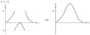
- FIG. 5 is a diagram showing a rotation angle data detected by the apparatus and the method for detecting slips of a mobile robot according to the exemplary embodiment of the present invention and data generated by processing the rotation angle data
- FIG. 6 is a diagram showing a processed estimated rotation angle and a measured rotation angle when the slips are generated at time t1, FIG.
- FIG. 7 is a diagram showing a first slip detecting result detected by the method for detecting slips of a mobile robot according to the exemplary embodiment of the present invention
- FIG. 8 is a diagram showing a process of determining whether an image acquisition unit is shielded by dividing an acquired image into four based on a heading orientation d of the mobile robot.
- the method for detecting slips of a mobile robot includes: a) estimating a first rotation angle estimated that the mobile robot rotates (S210); b) measuring a second rotation angle generated by actually rotating the mobile robot (S210); and c) detecting a first slip by obtaining the error angle between the first rotation angle and the second rotation angle and calculating the slip direction and the slip angle of the mobile robot based on the error angle (S200).
- the method for detecting slips of a mobile robot further includes d) detecting a second slip by calculation variations of at least two sequentially input images (S300).
- the method for detecting slips of a mobile robot further includes: e) detecting a type of slips based on the detected first and second slips (S400) and selectively escaping the slip region according to a type of detected slips (S500).
- the method for detecting slips of a mobile robot further includes f) recovering a location of the mobile robot based of the slip direction, the slip angle, and the image variations (S600).
- the estimation of the first rotation angle (S120) detects a first angular velocity that is the rotation speed of the left wheel driving unit of the mobile robot and a second angular velocity that is the rotation speed of the right wheel driving unit and calculates the first rotation angle based on a difference between the first angular velocity and the second angular velocity and a diameter of the wheel of the mobile robot.
- the mobile robot In the detecting of the first slip (S200), the mobile robot escapes the slip region by obtaining the error angle between the first rotation angle and the second rotation angle and comparing the obtained error angle with a reference error angle and determining that the slip is generated in the mobile robot if it is determined that the error angle is larger than the reference error angle (S500).
- the mobile robot 100 moves backward by a predetermined distance or for a predetermined time and then, moves forward in a direction opposite to the slip direction and as a result, escapes the slip region.
- the slip detecting unit 210 determines that the slip is generated at the right wheel of the mobile robot when the sign of the error angle has a negative value and the mobile robot 100 move backward by a predetermined distance or for a predetermined time according to the escape control signal of the slip detecting unit and then, move forward in the left direction and as a result, escapes the slip region.
- the slip detecting unit 210 determines that the slip is generated at the left wheel of the mobile robot when the sign of the error angle has a positive value and the mobile robot 100 move backward by a predetermined distance or for a predetermined time according to the escape control signal of the slip detecting unit and then, move forward in the right direction and as a result, escapes the slip region.
- the detecting of the first slip will be described in more detail with reference to FIGS. 4 to 6 .
- the first rotation angle estimating unit 220 integrates an angular velocity component of the rotation axis of the robot driver measured by the driving speed detecting unit 230 to output ⁇ enco that is the rotation angle estimated that the mobile robot 100 rotates.
- the driving speed detecting unit 230 measures a driving rotation angular velocity wL and wR from the left wheel 151 and the right wheel 152 by a differential driving scheme.
- the moving speed of the mobile robot may be obtained by multiplying a radius of the wheel by an average of angular velocity.
- the rotation angle ⁇ enco may be obtained by multiplying a radius of the wheel by a difference between angular velocities of both wheels.
- the rotation angle ⁇ enco may be obtained by the driving speed detecting unit 230 like the encoder.
- a linear velocity v and a rotation angular velocity w of the mobile robot 100 may be obtained using the following Equations 1 and 2.
- v wR * rR + wL * + rL / 2
- w wR * rR ⁇ wL * rL / B
- v and w each are the linear velocity and the rotation angular velocity of the mobile robot
- rR is a radius of the right wheel
- rL is a radius of the left wheel
- wR is a right wheel rotation speed
- wL is a left wheel rotation speed
- B is a distance between both wheels.
- the rotation angle of the mobile robot is limited to - ⁇ to + ⁇ and therefore, when an absolute value of the rotation angle exceeds ⁇ , the sign is changed and thus, the continuous process cannot be performed. Therefore, the pre-processing process is again performed thereon.
- the pre-processing process will be described in detail with reference to FIG. 5 .
- the error angle has a value of - ⁇ to + ⁇ and therefore, when the error angle exceeds + ⁇ , has a value of - ⁇ to 0. Therefore, the error angle has a discontinuous period for the moving time corresponding to + ⁇ and - ⁇ . Therefore, as shown in FIG. 5B , the slip detecting unit 210 moves the error angle of the discontinuous period in a y-axis direction in parallel and pre-processes the error angle so that the discontinuous period is a continuous period.
- the side slip of the mobile robot may be determined by the difference between patterns of ⁇ gyro and ⁇ enco for a predetermined time.
- the slip state needs to be maintained for a predetermined time. Therefore, in the case of determining the slip, moving averages are obtained in a predetermined sampling window period for the output data of the rotation angles ⁇ gyro and ⁇ enco and then, it is determined whether the slip is present based on a difference between the moving averages.
- SlipAngle (n) is an error angle for the rotation angle output from the first rotation angle measuring unit and the second rotation angle measuring unit for the slip of the side direction.
- the slip detecting unit 210 determines that the slip is generated when the absolute value of the measured SlipAngle is larger than a defined reference value.
- the slip is generated from the left of the heading direction of the robot and when the sign of the SlipAngle is negative, the slip is generated from the right thereof.
- the mobile robot does not head in a direction in which the slip is generated to reduce the location error and therefore, the mobile robot slightly moves backward and then, may perform a moving strategy that averts the mobile robot to the opposite direction.
- r is a radius of the wheel
- dx(n) and dy(n) each are a location error of an X-axis direction and a Y-axis direction and ( ⁇ L + ⁇ R )*r/2 is a moving speed of the mobile robot
- W is a window size applied to row data in order to perform the data processing.
- the slip detecting unit 210 compares the image variations with the reference variations to estimate that the mobile robot is congested when the image variations are smaller than the reference variations, thereby calculating a congested frequency.
- the slip detecting unit 210 detects the generation of the second slip when the congested frequency is larger than the reference frequency and the speed of the mobile robot based on the error angle is larger than the reference speed.
- the image variation calculating unit 250 detects a change in brightness of the image acquired by the image acquisition unit 110 to detect that the mobile robot 100 moves downwardly of obstacles such as a table. For example, the image variation calculating unit 250 detects that the image acquisition unit 110 of the mobile robot 100 is shielded by obstacles by using the brightness average and variance of the acquired image.
- the slip detecting unit 210 outputs a signal that controls the movement of the mobile robot 100 based on local information acquired from the inertial sensor 240 such as the gyroscope and the wheel encoder 23.
- the above-mentioned inertial sensor 240 detects inertia to confirm a heading direction of the mobile robot 100 and the sensing information of the inertial sensor 240 and the sensing information of the wheel encoder 230 configure the odometry of the mobile robot 100.
- a first slip detecting result detected by the method for detecting slips of the mobile robot according to the exemplary embodiment of the present invention will be described with reference to FIG. 7 .
- each of the L1 and L2 is value obtained by differentiating the direction angle in the wheel encoder and gyro sensor space and L3 is a value obtained by summing a difference between the L1 and the L2 for a predetermined time window.
- L3 is larger than a predetermined value, it is sorted into the slip.
- the first peak corresponds to a case in which a temporary slip is generated due to a slightly rugged floor and a second peak corresponds to a case in which the heading of the wheel encoder and the gyro sensor deviate from each other due to asynchronization when the 180° rotation starts and ends.
- the third peak corresponds to a case in which the slip defined by the inventors is generated, which uses a threshold of about 1.2 herein.
- the slip is generated by allow a cleaning robot to perform a trial of strength in a side direction for a predetermined time.
- the detecting of the second slip will be described in more detail with reference to FIG. 8 .
- the slip detecting unit 210 divides the input image into an N region and increases an object region by 1/N based on the heading direction or the opposite direction of the mobile robot to calculate an average and a variance of each increased region (S330) and when the image is not shielded based on the variations of the average and variance values of each region, the input image is estimated as being congested if it is determined that the image variations are smaller than the reference variations, thereby calculating the congested frequency (S340).
- the slip detecting unit 210 detects the generation of the second slip when the congested frequency is larger than the reference frequency and the speed of the mobile robot based on the error angle is larger than the reference speed.
- the brightness average of an image frame is gradually reduced and thus, a variance value of brightness may be increased or reduced.
- it may determine whether the mobile robot 100 is shielded by obtaining the average and variance of the overall image using the brightness average values of each region divided by quartering the image acquired by the image acquisition unit 110 based on a heading direction d of the mobile robot 100.
- a vision sensor like a camera in order to detect a front slip, a vision sensor like a camera has been used, but methods of using a difference between revolutions of the driving wheels using an accelerometer or a coupled driving wheel may be used.
- the case in which the defined reference value is smaller than the variations is estimated as the case in which the congestion of the camera pose occurs.
- the robot when the driving speed of the robot is a predetermined value or more and thus, the robot is not in a stop state, it is determined that the front slip is generated or the robot is sandwiched between both sides.
- the slip detecting unit 210 When the slip detecting unit 210 detects the front slip, the slip detecting unit 210 outputs the control signal so as to allow the mobile robot to be headed while avoiding the slip generation region after the mobile robot moves backward by a predetermined distance or for a predetermined time. That is, in the case of the front slip, the mobile robot rotates backward and comes out and thus, may avoid the environment in which the slip may occur and the estimated location of the robot is corrected by multiplying the congested frequency by the moving speed of the robot and retreating backward.
- the mobile robot using the SLAM scheme in which the single camera to which the present invention is applied is mounted processes 2 to 3 frames per second and thus, there is a need to correct the coordinate information of the falsely registered landmark on an extended Kalman filter (EKF) map while the front slip is detected by a visual odometry. Therefore, the error occurring due to the slip may be calibrated by the following observing measurement by increasing covariance for the landmarks registered in a landmark initialization buffer. Further, when the side slip is detected, it may be processed at a relatively short time and therefore, the current location information of the mobile robot is calibrated at the time of updating the EKF.
- EKF extended Kalman filter
Applications Claiming Priority (2)
| Application Number | Priority Date | Filing Date | Title |
|---|---|---|---|
| PCT/KR2009/006367 WO2011052827A1 (ko) | 2009-10-30 | 2009-10-30 | 이동 로봇의 슬립 감지 장치 및 방법 |
| KR1020090104168A KR101152720B1 (ko) | 2009-10-30 | 2009-10-30 | 이동 로봇의 슬립 감지 장치 및 방법 |
Publications (3)
| Publication Number | Publication Date |
|---|---|
| EP2495079A1 EP2495079A1 (en) | 2012-09-05 |
| EP2495079A4 EP2495079A4 (en) | 2016-11-09 |
| EP2495079B1 true EP2495079B1 (en) | 2018-09-05 |
Family
ID=43922245
Family Applications (1)
| Application Number | Title | Priority Date | Filing Date |
|---|---|---|---|
| EP09850898.9A Not-in-force EP2495079B1 (en) | 2009-10-30 | 2009-10-30 | Slip detection apparatus and method for a mobile robot |
Country Status (6)
| Country | Link |
|---|---|
| US (1) | US8873832B2 (zh) |
| EP (1) | EP2495079B1 (zh) |
| JP (1) | JP5421461B2 (zh) |
| KR (1) | KR101152720B1 (zh) |
| CN (1) | CN102666032B (zh) |
| WO (1) | WO2011052827A1 (zh) |
Families Citing this family (56)
| Publication number | Priority date | Publication date | Assignee | Title |
|---|---|---|---|---|
| US11835343B1 (en) * | 2004-08-06 | 2023-12-05 | AI Incorporated | Method for constructing a map while performing work |
| US8930023B2 (en) * | 2009-11-06 | 2015-01-06 | Irobot Corporation | Localization by learning of wave-signal distributions |
| KR20110021191A (ko) * | 2009-08-25 | 2011-03-04 | 삼성전자주식회사 | 로봇의 슬립 감지 장치 및 방법 |
| US8798840B2 (en) | 2011-09-30 | 2014-08-05 | Irobot Corporation | Adaptive mapping with spatial summaries of sensor data |
| CN105717924B (zh) * | 2012-06-08 | 2018-12-28 | 艾罗伯特公司 | 使用差动传感器或视觉测量的地毯偏移估计 |
| KR101938642B1 (ko) * | 2012-06-12 | 2019-01-15 | 엘지전자 주식회사 | 유리창 청소 장치 및 그의 제어방법 |
| KR20140062288A (ko) * | 2012-11-14 | 2014-05-23 | 한국전자통신연구원 | 로봇 컴포넌트 오류 처리 장치 및 그 방법 |
| KR101511992B1 (ko) * | 2013-09-06 | 2015-04-14 | 현대모비스(주) | 조향 휠 제어 방법 및 이를 위한 위한 시스템 |
| JP6178677B2 (ja) * | 2013-09-09 | 2017-08-09 | シャープ株式会社 | 自走式電子機器 |
| CN103552091B (zh) * | 2013-09-29 | 2015-09-16 | 江苏恒义汽配制造有限公司 | 机械手装置上的移送滚轮与轨道状态的检测装置 |
| KR101523848B1 (ko) * | 2013-11-28 | 2015-05-28 | 울산대학교 산학협력단 | 이동 로봇의 슬립 추정 장치 및 그 방법 |
| WO2017184478A1 (en) * | 2016-04-17 | 2017-10-26 | President And Fellows Of Harvard College | Magnetic receptive sensor and optimized drawing and erasing for vertically driving robot |
| JP6481347B2 (ja) * | 2014-11-28 | 2019-03-13 | 村田機械株式会社 | 移動量推定装置、自律移動体、及び移動量の推定方法 |
| KR101697857B1 (ko) * | 2015-04-08 | 2017-01-18 | 엘지전자 주식회사 | 이동 로봇 및 그의 위치인식방법 |
| JP6743828B2 (ja) | 2015-04-17 | 2020-08-19 | アクチエボラゲット エレクトロルックス | ロボット掃除機およびロボット掃除機を制御する方法 |
| KR101649665B1 (ko) * | 2015-04-29 | 2016-08-30 | 엘지전자 주식회사 | 이동 로봇 및 그 제어방법 |
| GB2538779B (en) | 2015-05-28 | 2017-08-30 | Dyson Technology Ltd | A method of controlling a mobile robot |
| JP7036531B2 (ja) | 2016-01-08 | 2022-03-15 | 東芝ライフスタイル株式会社 | 自律走行体 |
| JP7035300B2 (ja) | 2016-03-15 | 2022-03-15 | アクチエボラゲット エレクトロルックス | ロボット清掃デバイス、ロボット清掃デバイスにおける、断崖検出を遂行する方法、コンピュータプログラム、およびコンピュータプログラム製品 |
| KR101854680B1 (ko) | 2016-04-29 | 2018-06-14 | 엘지전자 주식회사 | 이동 로봇 및 그 제어방법 |
| KR101979760B1 (ko) * | 2016-07-14 | 2019-05-17 | 엘지전자 주식회사 | 이동로봇 |
| US10274325B2 (en) * | 2016-11-01 | 2019-04-30 | Brain Corporation | Systems and methods for robotic mapping |
| WO2018219473A1 (en) | 2017-06-02 | 2018-12-06 | Aktiebolaget Electrolux | Method of detecting a difference in level of a surface in front of a robotic cleaning device |
| KR102024089B1 (ko) | 2017-08-07 | 2019-09-23 | 엘지전자 주식회사 | 로봇 청소기 |
| KR102014141B1 (ko) | 2017-08-07 | 2019-10-21 | 엘지전자 주식회사 | 로봇청소기 |
| KR102000068B1 (ko) | 2017-08-07 | 2019-07-15 | 엘지전자 주식회사 | 청소기 |
| KR102014140B1 (ko) | 2017-08-07 | 2019-08-26 | 엘지전자 주식회사 | 청소기 |
| KR102021828B1 (ko) | 2017-08-07 | 2019-09-17 | 엘지전자 주식회사 | 청소기 |
| KR102014142B1 (ko) | 2017-08-07 | 2019-08-26 | 엘지전자 주식회사 | 로봇 청소기 |
| KR102033936B1 (ko) | 2017-08-07 | 2019-10-18 | 엘지전자 주식회사 | 로봇청소기 |
| KR102011827B1 (ko) * | 2017-08-07 | 2019-08-19 | 엘지전자 주식회사 | 로봇청소기 및 그 제어방법 |
| CN107348910B (zh) | 2017-09-12 | 2019-10-08 | 珠海市一微半导体有限公司 | 机器人打滑的检测方法和建图方法及芯片 |
| CN109669350B (zh) * | 2017-10-13 | 2021-07-20 | 电子科技大学中山学院 | 一种三轮全向移动机器人车轮滑动定量估计方法 |
| JP7078057B2 (ja) * | 2017-12-05 | 2022-05-31 | 日本電産株式会社 | 移動ロボットの制御装置および移動ロボットシステム |
| KR102478124B1 (ko) * | 2017-12-05 | 2022-12-16 | 현대자동차주식회사 | 차량 구동휠 제어시스템 및 이를 이용한 차량 구동휠 제어방법 |
| US11926038B2 (en) * | 2018-01-10 | 2024-03-12 | Sony Corporation | Information processing apparatus and information processing method |
| KR102045003B1 (ko) | 2018-01-25 | 2019-11-14 | 엘지전자 주식회사 | 로봇청소기의 제어방법 |
| JP7047594B2 (ja) * | 2018-05-23 | 2022-04-05 | トヨタ自動車株式会社 | 自律移動体、その衝突位置検出方法、及びプログラム |
| CN109394095B (zh) * | 2018-10-23 | 2020-09-15 | 珠海市一微半导体有限公司 | 一种机器人运动地毯偏移的控制方法、芯片及清洁机器人 |
| CN111700543B (zh) * | 2019-03-18 | 2022-12-02 | 北京奇虎科技有限公司 | 遇障处理方法、装置、设备及计算机可读存储介质 |
| US11442454B2 (en) | 2019-03-21 | 2022-09-13 | Sharkninja Operating Llc | Adaptive sensor array system and method |
| AU2020321757B2 (en) * | 2019-07-31 | 2023-10-26 | Lg Electronics Inc. | Mobile robot and method for calculating moving distance of mobile robot |
| KR102251550B1 (ko) * | 2019-07-31 | 2021-05-12 | 엘지전자 주식회사 | 이동 로봇 및 그 제어방법 |
| TWI735022B (zh) * | 2019-08-08 | 2021-08-01 | 和碩聯合科技股份有限公司 | 語意地圖定向裝置、方法及機器人 |
| CN112549072A (zh) * | 2019-09-10 | 2021-03-26 | 苏州科瓴精密机械科技有限公司 | 机器人的打滑检测方法 |
| CN110716551A (zh) * | 2019-11-06 | 2020-01-21 | 小狗电器互联网科技(北京)股份有限公司 | 移动机器人行驶策略确定方法、装置以及移动机器人 |
| CN114153197B (zh) * | 2020-08-17 | 2023-08-18 | 速感科技(北京)有限公司 | 自主移动设备的脱困方法及装置 |
| US20230333560A1 (en) * | 2020-09-01 | 2023-10-19 | Ceva Technologies, Inc. | Planar robots dead-reckoning with optical flow, wheel encoder and inertial measurement unit |
| CN113427485B (zh) * | 2021-06-04 | 2022-08-12 | 北京旷视科技有限公司 | 移动机器人的打滑监控方法、装置及移动机器人 |
| CN113551692B (zh) * | 2021-07-19 | 2024-04-02 | 杭州迅蚁网络科技有限公司 | 无人机磁力计和相机安装角度校准方法、装置 |
| CN113894843A (zh) * | 2021-07-22 | 2022-01-07 | 深兰科技(上海)有限公司 | 移动机器人的打滑检测方法及相关装置 |
| CN114325744B (zh) * | 2021-12-29 | 2022-08-19 | 广东工业大学 | 一种无人车打滑检测方法、系统、设备及介质 |
| CN114659819B (zh) * | 2022-04-14 | 2024-03-19 | 阳春新钢铁有限责任公司 | 一种变频控制下的打滑检测方法 |
| KR20230158668A (ko) * | 2022-05-11 | 2023-11-21 | 삼성전자주식회사 | 로봇 및 그 제어 방법 |
| WO2024057487A1 (ja) * | 2022-09-15 | 2024-03-21 | 株式会社Fuji | 移動体および移動体システム |
| CN115793433B (zh) * | 2023-01-06 | 2023-05-05 | 北京史河科技有限公司 | 一种机器人下滑纠偏控制方法和下滑纠偏底盘、机器人 |
Family Cites Families (14)
| Publication number | Priority date | Publication date | Assignee | Title |
|---|---|---|---|---|
| JP3395874B2 (ja) | 1996-08-12 | 2003-04-14 | ミノルタ株式会社 | 移動走行車 |
| JP4480843B2 (ja) | 2000-04-03 | 2010-06-16 | ソニー株式会社 | 脚式移動ロボット及びその制御方法、並びに、脚式移動ロボット用相対移動測定センサ |
| KR100500842B1 (ko) * | 2002-10-31 | 2005-07-12 | 삼성광주전자 주식회사 | 로봇청소기와, 그 시스템 및 제어방법 |
| JPWO2004106009A1 (ja) * | 2003-06-02 | 2006-07-20 | 松下電器産業株式会社 | 物品取扱いシステムおよび物品取扱いサーバ |
| JP2005022040A (ja) * | 2003-07-03 | 2005-01-27 | Toyota Motor Corp | 位置ずれを修正する歩行ロボットとその制御方法 |
| JP2005222226A (ja) * | 2004-02-04 | 2005-08-18 | Funai Electric Co Ltd | 自律走行ロボットクリーナー |
| KR20050108923A (ko) * | 2004-05-14 | 2005-11-17 | 삼성광주전자 주식회사 | 모빌로봇, 모빌로봇 시스템, 및 그 경로보정방법 |
| JP2006068884A (ja) * | 2004-09-06 | 2006-03-16 | Sony Corp | ロボット装置及びその制御方法、並びに受動車輪装置 |
| US7389166B2 (en) * | 2005-06-28 | 2008-06-17 | S.C. Johnson & Son, Inc. | Methods to prevent wheel slip in an autonomous floor cleaner |
| KR101297388B1 (ko) * | 2006-06-16 | 2013-08-19 | 삼성전자주식회사 | 위치 보정 기능을 제공하는 이동 장치 및 위치 보정 방법 |
| KR100855469B1 (ko) * | 2006-09-13 | 2008-09-01 | 삼성전자주식회사 | 이동 로봇의 자세 추정 장치 및 방법 |
| KR100843096B1 (ko) * | 2006-12-21 | 2008-07-02 | 삼성전자주식회사 | 이동 로봇의 주행 상태 판별 장치 및 방법 |
| JP4779982B2 (ja) * | 2007-02-02 | 2011-09-28 | トヨタ自動車株式会社 | 移動体及び移動体の制御方法 |
| KR101409987B1 (ko) * | 2007-12-11 | 2014-06-23 | 삼성전자주식회사 | 이동 로봇의 자세 보정 방법 및 장치 |
-
2009
- 2009-10-30 KR KR1020090104168A patent/KR101152720B1/ko active IP Right Grant
- 2009-10-30 WO PCT/KR2009/006367 patent/WO2011052827A1/ko active Application Filing
- 2009-10-30 CN CN200980162244.7A patent/CN102666032B/zh not_active Expired - Fee Related
- 2009-10-30 EP EP09850898.9A patent/EP2495079B1/en not_active Not-in-force
- 2009-10-30 JP JP2012536639A patent/JP5421461B2/ja not_active Expired - Fee Related
- 2009-10-30 US US13/504,510 patent/US8873832B2/en active Active
Non-Patent Citations (1)
| Title |
|---|
| None * |
Also Published As
| Publication number | Publication date |
|---|---|
| KR101152720B1 (ko) | 2012-06-18 |
| WO2011052827A1 (ko) | 2011-05-05 |
| EP2495079A1 (en) | 2012-09-05 |
| KR20110047505A (ko) | 2011-05-09 |
| CN102666032B (zh) | 2015-01-07 |
| CN102666032A (zh) | 2012-09-12 |
| JP5421461B2 (ja) | 2014-02-19 |
| US20120219207A1 (en) | 2012-08-30 |
| EP2495079A4 (en) | 2016-11-09 |
| JP2013508183A (ja) | 2013-03-07 |
| US8873832B2 (en) | 2014-10-28 |
Similar Documents
| Publication | Publication Date | Title |
|---|---|---|
| EP2495079B1 (en) | Slip detection apparatus and method for a mobile robot | |
| US10133278B2 (en) | Apparatus of controlling movement of mobile robot mounted with wide angle camera and method thereof | |
| KR101234798B1 (ko) | 이동 로봇의 위치 측정 방법 및 장치 | |
| KR100922494B1 (ko) | 이동 로봇의 자세 측정 방법 및 상기 방법을 이용한 위치측정 방법 및 장치 | |
| CN109394095B (zh) | 一种机器人运动地毯偏移的控制方法、芯片及清洁机器人 | |
| EP2495632B1 (en) | Map generating and updating method for mobile robot position recognition | |
| US7507948B2 (en) | Method of detecting object using structured light and robot using the same | |
| EP3842193A1 (en) | Anti-collision detection method for floor sweeping robot | |
| KR102079940B1 (ko) | 마찰계수 추정 기능을 갖는 이동 로봇 및 마찰계수 추정 방법 | |
| KR100871114B1 (ko) | 이동로봇 및 그 동작방법 | |
| KR101439921B1 (ko) | 비젼 센서 정보와 모션 센서 정보를 융합한 모바일 로봇용 slam 시스템 | |
| US20210232151A1 (en) | Systems And Methods For VSLAM Scale Estimation Using Optical Flow Sensor On A Robotic Device | |
| TW202024666A (zh) | 資訊處理裝置以及移動機器人 | |
| KR100784125B1 (ko) | 단일 카메라를 이용한 이동 로봇의 랜드 마크의 좌표 추출방법 | |
| CN112697153A (zh) | 自主移动设备的定位方法、电子设备及存储介质 | |
| KR100792852B1 (ko) | 단일 카메라를 이용한 이동 로봇의 랜드 마크 거리추출방법 | |
| Fourre et al. | Autonomous rgbd-based industrial staircase localization from tracked robots | |
| TWI711913B (zh) | 資訊處理裝置以及移動機器人 | |
| KR20050011054A (ko) | 주행 바닥면 영상정보를 이용한 이동로봇의 주행제어방법 | |
| KR20050011053A (ko) | 천장 영상을 이용한 청소용 로봇의 자기위치 추정방법 | |
| KR101243133B1 (ko) | 이동로봇의 위치추정 장치 및 방법 | |
| KR101376536B1 (ko) | 센서 융합을 이용한 모바일 객체의 위치 인식방법 및 그 장치 | |
| JP7155686B2 (ja) | 自律移動体の位置推定装置 | |
| JP2022071611A (ja) | 車両位置制御装置および自律走行装置 | |
| Althoefer et al. | Tractive Force Prediction for Unmanned Ground Vehicles in Rough Terrain |
Legal Events
| Date | Code | Title | Description |
|---|---|---|---|
| PUAI | Public reference made under article 153(3) epc to a published international application that has entered the european phase |
Free format text: ORIGINAL CODE: 0009012 |
|
| 17P | Request for examination filed |
Effective date: 20120427 |
|
| AK | Designated contracting states |
Kind code of ref document: A1 Designated state(s): AT BE BG CH CY CZ DE DK EE ES FI FR GB GR HR HU IE IS IT LI LT LU LV MC MK MT NL NO PL PT RO SE SI SK SM TR |
|
| RIN1 | Information on inventor provided before grant (corrected) |
Inventor name: KIM, HYUNG O Inventor name: PARK, SEONG JU Inventor name: LEE, JAE YOUNG Inventor name: LEE, HEE KONG Inventor name: DANIEL, JAMES STONIER Inventor name: SHIN, KYUNG CHUL |
|
| DAX | Request for extension of the european patent (deleted) | ||
| REG | Reference to a national code |
Ref country code: DE Ref legal event code: R079 Ref document number: 602009054404 Country of ref document: DE Free format text: PREVIOUS MAIN CLASS: B25J0019020000 Ipc: B25J0009160000 |
|
| RA4 | Supplementary search report drawn up and despatched (corrected) |
Effective date: 20161010 |
|
| RIC1 | Information provided on ipc code assigned before grant |
Ipc: B25J 9/16 20060101AFI20161004BHEP Ipc: G05D 1/02 20060101ALI20161004BHEP |
|
| GRAP | Despatch of communication of intention to grant a patent |
Free format text: ORIGINAL CODE: EPIDOSNIGR1 |
|
| INTG | Intention to grant announced |
Effective date: 20180524 |
|
| GRAS | Grant fee paid |
Free format text: ORIGINAL CODE: EPIDOSNIGR3 |
|
| GRAA | (expected) grant |
Free format text: ORIGINAL CODE: 0009210 |
|
| AK | Designated contracting states |
Kind code of ref document: B1 Designated state(s): AT BE BG CH CY CZ DE DK EE ES FI FR GB GR HR HU IE IS IT LI LT LU LV MC MK MT NL NO PL PT RO SE SI SK SM TR |
|
| REG | Reference to a national code |
Ref country code: GB Ref legal event code: FG4D |
|
| REG | Reference to a national code |
Ref country code: CH Ref legal event code: EP |
|
| REG | Reference to a national code |
Ref country code: AT Ref legal event code: REF Ref document number: 1037269 Country of ref document: AT Kind code of ref document: T Effective date: 20180915 |
|
| REG | Reference to a national code |
Ref country code: IE Ref legal event code: FG4D |
|
| REG | Reference to a national code |
Ref country code: DE Ref legal event code: R096 Ref document number: 602009054404 Country of ref document: DE |
|
| REG | Reference to a national code |
Ref country code: FR Ref legal event code: PLFP Year of fee payment: 10 |
|
| REG | Reference to a national code |
Ref country code: NL Ref legal event code: MP Effective date: 20180905 |
|
| REG | Reference to a national code |
Ref country code: LT Ref legal event code: MG4D |
|
| PG25 | Lapsed in a contracting state [announced via postgrant information from national office to epo] |
Ref country code: LT Free format text: LAPSE BECAUSE OF FAILURE TO SUBMIT A TRANSLATION OF THE DESCRIPTION OR TO PAY THE FEE WITHIN THE PRESCRIBED TIME-LIMIT Effective date: 20180905 Ref country code: BG Free format text: LAPSE BECAUSE OF FAILURE TO SUBMIT A TRANSLATION OF THE DESCRIPTION OR TO PAY THE FEE WITHIN THE PRESCRIBED TIME-LIMIT Effective date: 20181205 Ref country code: FI Free format text: LAPSE BECAUSE OF FAILURE TO SUBMIT A TRANSLATION OF THE DESCRIPTION OR TO PAY THE FEE WITHIN THE PRESCRIBED TIME-LIMIT Effective date: 20180905 Ref country code: NO Free format text: LAPSE BECAUSE OF FAILURE TO SUBMIT A TRANSLATION OF THE DESCRIPTION OR TO PAY THE FEE WITHIN THE PRESCRIBED TIME-LIMIT Effective date: 20181205 Ref country code: GR Free format text: LAPSE BECAUSE OF FAILURE TO SUBMIT A TRANSLATION OF THE DESCRIPTION OR TO PAY THE FEE WITHIN THE PRESCRIBED TIME-LIMIT Effective date: 20181206 Ref country code: SE Free format text: LAPSE BECAUSE OF FAILURE TO SUBMIT A TRANSLATION OF THE DESCRIPTION OR TO PAY THE FEE WITHIN THE PRESCRIBED TIME-LIMIT Effective date: 20180905 |
|
| REG | Reference to a national code |
Ref country code: AT Ref legal event code: MK05 Ref document number: 1037269 Country of ref document: AT Kind code of ref document: T Effective date: 20180905 |
|
| PG25 | Lapsed in a contracting state [announced via postgrant information from national office to epo] |
Ref country code: HR Free format text: LAPSE BECAUSE OF FAILURE TO SUBMIT A TRANSLATION OF THE DESCRIPTION OR TO PAY THE FEE WITHIN THE PRESCRIBED TIME-LIMIT Effective date: 20180905 Ref country code: LV Free format text: LAPSE BECAUSE OF FAILURE TO SUBMIT A TRANSLATION OF THE DESCRIPTION OR TO PAY THE FEE WITHIN THE PRESCRIBED TIME-LIMIT Effective date: 20180905 |
|
| PG25 | Lapsed in a contracting state [announced via postgrant information from national office to epo] |
Ref country code: CZ Free format text: LAPSE BECAUSE OF FAILURE TO SUBMIT A TRANSLATION OF THE DESCRIPTION OR TO PAY THE FEE WITHIN THE PRESCRIBED TIME-LIMIT Effective date: 20180905 Ref country code: RO Free format text: LAPSE BECAUSE OF FAILURE TO SUBMIT A TRANSLATION OF THE DESCRIPTION OR TO PAY THE FEE WITHIN THE PRESCRIBED TIME-LIMIT Effective date: 20180905 Ref country code: IT Free format text: LAPSE BECAUSE OF FAILURE TO SUBMIT A TRANSLATION OF THE DESCRIPTION OR TO PAY THE FEE WITHIN THE PRESCRIBED TIME-LIMIT Effective date: 20180905 Ref country code: PL Free format text: LAPSE BECAUSE OF FAILURE TO SUBMIT A TRANSLATION OF THE DESCRIPTION OR TO PAY THE FEE WITHIN THE PRESCRIBED TIME-LIMIT Effective date: 20180905 Ref country code: NL Free format text: LAPSE BECAUSE OF FAILURE TO SUBMIT A TRANSLATION OF THE DESCRIPTION OR TO PAY THE FEE WITHIN THE PRESCRIBED TIME-LIMIT Effective date: 20180905 Ref country code: AT Free format text: LAPSE BECAUSE OF FAILURE TO SUBMIT A TRANSLATION OF THE DESCRIPTION OR TO PAY THE FEE WITHIN THE PRESCRIBED TIME-LIMIT Effective date: 20180905 Ref country code: IS Free format text: LAPSE BECAUSE OF FAILURE TO SUBMIT A TRANSLATION OF THE DESCRIPTION OR TO PAY THE FEE WITHIN THE PRESCRIBED TIME-LIMIT Effective date: 20190105 Ref country code: ES Free format text: LAPSE BECAUSE OF FAILURE TO SUBMIT A TRANSLATION OF THE DESCRIPTION OR TO PAY THE FEE WITHIN THE PRESCRIBED TIME-LIMIT Effective date: 20180905 Ref country code: EE Free format text: LAPSE BECAUSE OF FAILURE TO SUBMIT A TRANSLATION OF THE DESCRIPTION OR TO PAY THE FEE WITHIN THE PRESCRIBED TIME-LIMIT Effective date: 20180905 |
|
| PG25 | Lapsed in a contracting state [announced via postgrant information from national office to epo] |
Ref country code: SM Free format text: LAPSE BECAUSE OF FAILURE TO SUBMIT A TRANSLATION OF THE DESCRIPTION OR TO PAY THE FEE WITHIN THE PRESCRIBED TIME-LIMIT Effective date: 20180905 Ref country code: PT Free format text: LAPSE BECAUSE OF FAILURE TO SUBMIT A TRANSLATION OF THE DESCRIPTION OR TO PAY THE FEE WITHIN THE PRESCRIBED TIME-LIMIT Effective date: 20190105 Ref country code: SK Free format text: LAPSE BECAUSE OF FAILURE TO SUBMIT A TRANSLATION OF THE DESCRIPTION OR TO PAY THE FEE WITHIN THE PRESCRIBED TIME-LIMIT Effective date: 20180905 |
|
| REG | Reference to a national code |
Ref country code: CH Ref legal event code: PL |
|
| REG | Reference to a national code |
Ref country code: DE Ref legal event code: R097 Ref document number: 602009054404 Country of ref document: DE |
|
| REG | Reference to a national code |
Ref country code: BE Ref legal event code: MM Effective date: 20181031 |
|
| PG25 | Lapsed in a contracting state [announced via postgrant information from national office to epo] |
Ref country code: LU Free format text: LAPSE BECAUSE OF NON-PAYMENT OF DUE FEES Effective date: 20181030 |
|
| PLBE | No opposition filed within time limit |
Free format text: ORIGINAL CODE: 0009261 |
|
| STAA | Information on the status of an ep patent application or granted ep patent |
Free format text: STATUS: NO OPPOSITION FILED WITHIN TIME LIMIT |
|
| REG | Reference to a national code |
Ref country code: IE Ref legal event code: MM4A |
|
| PG25 | Lapsed in a contracting state [announced via postgrant information from national office to epo] |
Ref country code: DK Free format text: LAPSE BECAUSE OF FAILURE TO SUBMIT A TRANSLATION OF THE DESCRIPTION OR TO PAY THE FEE WITHIN THE PRESCRIBED TIME-LIMIT Effective date: 20180905 Ref country code: MC Free format text: LAPSE BECAUSE OF FAILURE TO SUBMIT A TRANSLATION OF THE DESCRIPTION OR TO PAY THE FEE WITHIN THE PRESCRIBED TIME-LIMIT Effective date: 20180905 |
|
| 26N | No opposition filed |
Effective date: 20190606 |
|
| PG25 | Lapsed in a contracting state [announced via postgrant information from national office to epo] |
Ref country code: LI Free format text: LAPSE BECAUSE OF NON-PAYMENT OF DUE FEES Effective date: 20181031 Ref country code: CH Free format text: LAPSE BECAUSE OF NON-PAYMENT OF DUE FEES Effective date: 20181031 Ref country code: SI Free format text: LAPSE BECAUSE OF FAILURE TO SUBMIT A TRANSLATION OF THE DESCRIPTION OR TO PAY THE FEE WITHIN THE PRESCRIBED TIME-LIMIT Effective date: 20180905 Ref country code: BE Free format text: LAPSE BECAUSE OF NON-PAYMENT OF DUE FEES Effective date: 20181031 |
|
| PG25 | Lapsed in a contracting state [announced via postgrant information from national office to epo] |
Ref country code: IE Free format text: LAPSE BECAUSE OF NON-PAYMENT OF DUE FEES Effective date: 20181030 |
|
| PG25 | Lapsed in a contracting state [announced via postgrant information from national office to epo] |
Ref country code: MT Free format text: LAPSE BECAUSE OF NON-PAYMENT OF DUE FEES Effective date: 20181030 |
|
| PGFP | Annual fee paid to national office [announced via postgrant information from national office to epo] |
Ref country code: DE Payment date: 20191021 Year of fee payment: 11 |
|
| PGFP | Annual fee paid to national office [announced via postgrant information from national office to epo] |
Ref country code: FR Payment date: 20191028 Year of fee payment: 11 |
|
| PG25 | Lapsed in a contracting state [announced via postgrant information from national office to epo] |
Ref country code: TR Free format text: LAPSE BECAUSE OF FAILURE TO SUBMIT A TRANSLATION OF THE DESCRIPTION OR TO PAY THE FEE WITHIN THE PRESCRIBED TIME-LIMIT Effective date: 20180905 |
|
| PGFP | Annual fee paid to national office [announced via postgrant information from national office to epo] |
Ref country code: GB Payment date: 20191021 Year of fee payment: 11 |
|
| PG25 | Lapsed in a contracting state [announced via postgrant information from national office to epo] |
Ref country code: MK Free format text: LAPSE BECAUSE OF NON-PAYMENT OF DUE FEES Effective date: 20180905 Ref country code: CY Free format text: LAPSE BECAUSE OF FAILURE TO SUBMIT A TRANSLATION OF THE DESCRIPTION OR TO PAY THE FEE WITHIN THE PRESCRIBED TIME-LIMIT Effective date: 20180905 Ref country code: HU Free format text: LAPSE BECAUSE OF FAILURE TO SUBMIT A TRANSLATION OF THE DESCRIPTION OR TO PAY THE FEE WITHIN THE PRESCRIBED TIME-LIMIT; INVALID AB INITIO Effective date: 20091030 |
|
| REG | Reference to a national code |
Ref country code: DE Ref legal event code: R119 Ref document number: 602009054404 Country of ref document: DE |
|
| GBPC | Gb: european patent ceased through non-payment of renewal fee |
Effective date: 20201030 |
|
| PG25 | Lapsed in a contracting state [announced via postgrant information from national office to epo] |
Ref country code: FR Free format text: LAPSE BECAUSE OF NON-PAYMENT OF DUE FEES Effective date: 20201031 Ref country code: DE Free format text: LAPSE BECAUSE OF NON-PAYMENT OF DUE FEES Effective date: 20210501 |
|
| PG25 | Lapsed in a contracting state [announced via postgrant information from national office to epo] |
Ref country code: GB Free format text: LAPSE BECAUSE OF NON-PAYMENT OF DUE FEES Effective date: 20201030 |