EP2493588B1 - Dispositif filtrant - Google Patents
Dispositif filtrant Download PDFInfo
- Publication number
- EP2493588B1 EP2493588B1 EP10773802.3A EP10773802A EP2493588B1 EP 2493588 B1 EP2493588 B1 EP 2493588B1 EP 10773802 A EP10773802 A EP 10773802A EP 2493588 B1 EP2493588 B1 EP 2493588B1
- Authority
- EP
- European Patent Office
- Prior art keywords
- filter
- holder
- holder arm
- arm
- tilt axis
- Prior art date
- Legal status (The legal status is an assumption and is not a legal conclusion. Google has not performed a legal analysis and makes no representation as to the accuracy of the status listed.)
- Active
Links
- 239000002775 capsule Substances 0.000 claims description 205
- 230000006835 compression Effects 0.000 claims description 73
- 238000007906 compression Methods 0.000 claims description 73
- 230000005484 gravity Effects 0.000 claims description 27
- 230000007246 mechanism Effects 0.000 claims description 16
- 238000009434 installation Methods 0.000 claims 1
- 239000012530 fluid Substances 0.000 description 60
- 238000001914 filtration Methods 0.000 description 24
- 238000000034 method Methods 0.000 description 15
- 239000000706 filtrate Substances 0.000 description 13
- 238000007789 sealing Methods 0.000 description 12
- 230000008901 benefit Effects 0.000 description 9
- 238000004519 manufacturing process Methods 0.000 description 9
- 238000009428 plumbing Methods 0.000 description 8
- 230000033001 locomotion Effects 0.000 description 6
- 238000011012 sanitization Methods 0.000 description 6
- 238000013461 design Methods 0.000 description 5
- 238000013022 venting Methods 0.000 description 4
- 239000003795 chemical substances by application Substances 0.000 description 3
- 230000008878 coupling Effects 0.000 description 3
- 238000010168 coupling process Methods 0.000 description 3
- 238000005859 coupling reaction Methods 0.000 description 3
- 238000005452 bending Methods 0.000 description 2
- 238000011109 contamination Methods 0.000 description 2
- 230000008569 process Effects 0.000 description 2
- 238000010926 purge Methods 0.000 description 2
- 230000009467 reduction Effects 0.000 description 2
- 229920006395 saturated elastomer Polymers 0.000 description 2
- 238000013341 scale-up Methods 0.000 description 2
- 239000004743 Polypropylene Substances 0.000 description 1
- 230000004075 alteration Effects 0.000 description 1
- 230000000845 anti-microbial effect Effects 0.000 description 1
- 230000000840 anti-viral effect Effects 0.000 description 1
- 238000013459 approach Methods 0.000 description 1
- 238000004140 cleaning Methods 0.000 description 1
- 230000009194 climbing Effects 0.000 description 1
- 238000010276 construction Methods 0.000 description 1
- 238000011118 depth filtration Methods 0.000 description 1
- 238000007599 discharging Methods 0.000 description 1
- 230000009977 dual effect Effects 0.000 description 1
- 230000005611 electricity Effects 0.000 description 1
- 230000007613 environmental effect Effects 0.000 description 1
- 239000000796 flavoring agent Substances 0.000 description 1
- 235000019634 flavors Nutrition 0.000 description 1
- 230000006872 improvement Effects 0.000 description 1
- 239000000463 material Substances 0.000 description 1
- 238000012986 modification Methods 0.000 description 1
- 230000004048 modification Effects 0.000 description 1
- 229920000515 polycarbonate Polymers 0.000 description 1
- 239000004417 polycarbonate Substances 0.000 description 1
- -1 polypropylene Polymers 0.000 description 1
- 229920001155 polypropylene Polymers 0.000 description 1
- 238000012545 processing Methods 0.000 description 1
- 238000005096 rolling process Methods 0.000 description 1
- 238000000926 separation method Methods 0.000 description 1
- 229910001220 stainless steel Inorganic materials 0.000 description 1
- 239000010935 stainless steel Substances 0.000 description 1
- 239000002699 waste material Substances 0.000 description 1
Images


Classifications
-
- B—PERFORMING OPERATIONS; TRANSPORTING
- B01—PHYSICAL OR CHEMICAL PROCESSES OR APPARATUS IN GENERAL
- B01D—SEPARATION
- B01D29/00—Filters with filtering elements stationary during filtration, e.g. pressure or suction filters, not covered by groups B01D24/00 - B01D27/00; Filtering elements therefor
- B01D29/39—Filters with filtering elements stationary during filtration, e.g. pressure or suction filters, not covered by groups B01D24/00 - B01D27/00; Filtering elements therefor with hollow discs side by side on, or around, one or more tubes, e.g. of the leaf type
-
- B—PERFORMING OPERATIONS; TRANSPORTING
- B01—PHYSICAL OR CHEMICAL PROCESSES OR APPARATUS IN GENERAL
- B01D—SEPARATION
- B01D29/00—Filters with filtering elements stationary during filtration, e.g. pressure or suction filters, not covered by groups B01D24/00 - B01D27/00; Filtering elements therefor
- B01D29/44—Edge filtering elements, i.e. using contiguous impervious surfaces
- B01D29/46—Edge filtering elements, i.e. using contiguous impervious surfaces of flat, stacked bodies
-
- B—PERFORMING OPERATIONS; TRANSPORTING
- B01—PHYSICAL OR CHEMICAL PROCESSES OR APPARATUS IN GENERAL
- B01D—SEPARATION
- B01D29/00—Filters with filtering elements stationary during filtration, e.g. pressure or suction filters, not covered by groups B01D24/00 - B01D27/00; Filtering elements therefor
- B01D29/96—Filters with filtering elements stationary during filtration, e.g. pressure or suction filters, not covered by groups B01D24/00 - B01D27/00; Filtering elements therefor in which the filtering elements are moved between filtering operations; Particular measures for removing or replacing the filtering elements; Transport systems for filters
-
- B—PERFORMING OPERATIONS; TRANSPORTING
- B23—MACHINE TOOLS; METAL-WORKING NOT OTHERWISE PROVIDED FOR
- B23Q—DETAILS, COMPONENTS, OR ACCESSORIES FOR MACHINE TOOLS, e.g. ARRANGEMENTS FOR COPYING OR CONTROLLING; MACHINE TOOLS IN GENERAL CHARACTERISED BY THE CONSTRUCTION OF PARTICULAR DETAILS OR COMPONENTS; COMBINATIONS OR ASSOCIATIONS OF METAL-WORKING MACHINES, NOT DIRECTED TO A PARTICULAR RESULT
- B23Q1/00—Members which are comprised in the general build-up of a form of machine, particularly relatively large fixed members
- B23Q1/25—Movable or adjustable work or tool supports
-
- Y—GENERAL TAGGING OF NEW TECHNOLOGICAL DEVELOPMENTS; GENERAL TAGGING OF CROSS-SECTIONAL TECHNOLOGIES SPANNING OVER SEVERAL SECTIONS OF THE IPC; TECHNICAL SUBJECTS COVERED BY FORMER USPC CROSS-REFERENCE ART COLLECTIONS [XRACs] AND DIGESTS
- Y10—TECHNICAL SUBJECTS COVERED BY FORMER USPC
- Y10T—TECHNICAL SUBJECTS COVERED BY FORMER US CLASSIFICATION
- Y10T29/00—Metal working
- Y10T29/49—Method of mechanical manufacture
- Y10T29/49826—Assembling or joining
Definitions
- Stacked, disk-type lenticular filters have been used in processing of fluids for commercial applications.
- the filters are assembled for operation inside a sanitary housing that is sealable from an ambient environment.
- the sanitary housing is typically a generally cylindrical pressure vessel that has structure for fluid ingress and egress.
- pressurized fluid to be filtered enters the sanitary housing through the fluid ingress and fills the area surrounding the disk-type lenticular filters.
- the fluid is then filtered through the filter elements, after which the filtered fluid enters the stacked inner core.
- the stacked inner core is fluidly connected to a fluid egress, which can route the filtered fluid (filtrate) to downstream plumbing.
- Such systems are often bulky, top-heavy and time consuming to assemble. In some cases, overhead lifts must be used to remove heavy parts from the stack between uses. Typically, such systems are bolted or otherwise fixed to a floor so that assembly and disassembly can be achieved without risk of tipping the system. Furthermore, such systems typically comprise several heavy and expensive metallic parts that must be cleaned and sanitized between uses. The sanitary housing, along with any other non-disposable wetted parts, must be carefully cleaned before each use. If the sanitary housing or other wetted parts are not properly cleaned, subsequent batches of fluid may be cross-contaminated. The sanitizing steps can add significant delay to processes. Often, significant quantities of sanitizing agent must be used to sanitize such parts. Consumption and disposal of such sanitizing agents can create undesirable environmental impact. Furthermore, such systems often require a skilled and trained operator for proper compression.
- Such systems are typically mounted, often bolted to the floor or a skid, as a permanent fixture in a given room at a manufacturing location.
- Each such room typically contains several large related manufacturing fixtures with associated plumbing that may be employed, for example, in scale-up manufacturing processes.
- a separate permanent filtration fixture must be provided in each room.
- the present disclosure relates generally to filtration systems comprising disposable filter capsules.
- the present disclosure further relates to a filter holder to hold and operate such disposable filter capsules.
- Such systems can eliminate the need for a separate sanitary housing, therefore eliminating cross-batch contamination.
- Such systems can be made mobile so that a single filtration system can serve multiple rooms in a manufacturing facility.
- Such systems can reduce or eliminate the need for sanitization between uses.
- Such systems can allow for easier loading and unloading of filter capsules from a filter holder.
- Such systems can further allow easier loading of filter capsules, while also providing a smaller footprint while the filter holder is in operation.
- the present disclosure provides a filter holder comprising a base for supporting the filter holder on a work surface, a tilting mechanism attached to the base, and a holder arm attached to the tilting mechanism at a tilt axis.
- the holder arm comprises a base end and a distal end. The holder arm is tiltable about the tilt axis to a service position and an ergonomic loading position.
- the holder arm comprises a compression plate proximate the base end and a holding plate opposite the compression plate.
- the compression plate is continuously adjustable by a filter compression adjustment.
- the filter compression adjustment comprises a torque limiter.
- the torque limiter may have a torque limit of less than about 12 N•m.
- the tilt axis is located a first distance from the work surface and the base end of the holder arm is located a second distance from the tilt axis, the second distance being less than the first distance.
- the holder arm may comprise a front support bar and a rear support bar, the holding plate being slidably connected to the front support bar and the rear support bar.
- the compression plate is slidably connected to the front support bar and the rear support bar.
- front support bar and the rear support bar each comprise a plurality of plate positioning grooves. In some embodiments, when the holder arm is in the ergonomic loading position, the front support bar is positioned below the tilt axis, and the rear support bar is positioned at or above the tilt axis.
- the holder arm when in the service position, the holder arm is oriented orthogonal to the work surface, and when in the ergonomic loading position, the holder arm is oriented parallel to the work surface.
- the tilt axis is located a first distance from the work surface, the first distance being in a range from about 71 cm (about 28 inches) to about 102 cm (about 40 inches).
- the center of gravity of the holder arm when the holder arm is in the ergonomic loading position the center of gravity of the holder arm is not vertically aligned with the tilt axis, and, when the holder arm is in the service position, the center of gravity of the holder arm is substantially vertically aligned with the tilt axis.
- the filter holder is mobile.
- the base comprises one or more casters.
- the present disclosure also provides a filter system comprising a filter holder as described above and a filter capsule stack loaded onto the holder arm.
- a filter system comprising a filter holder as described above and a filter capsule stack loaded onto the holder arm.
- the center of gravity of the holder arm loaded with the filter capsule stack is not vertically aligned with the tilt axis, and, when the holder arm is in the service position, the center of gravity of the holder arm loaded with the filter capsule stack is substantially vertically aligned with the tilt axis.
- the present disclosure further provides a method of operating a filter holder comprising tilting a holder arm to an ergonomic loading position, loading a filter capsule stack onto the holder arm, and tilting the holder arm about a tilt axis to a service position.
- loading the filter capsule stack onto the holder arm comprises compressing the filter capsule stack between a compression plate and a holding plate.
- the method may further comprise locking the holding plate to prevent it from sliding.
- the method further comprises adjusting the compression of the filter capsule stack between the compression plate and the holding plate.
- compression of the filter capsule stack is adjusted by a filter compression adjustment comprising a torque limiter, wherein the torque limit is less than about 12 N•m.
- the method further comprises tilting the holder arm from the service position back to the ergonomic loading position and unloading the filter capsule stack from the holder arm.
- unloading the filter capsule stack from the holder arm comprises rotating a filter capsule over a front support bar.
- rotating the filter capsule over a front support bar comprises engaging a fulcrum lug on the filter capsule against the front support bar and rotating the filter capsule about the fulcrum lug to roll the filter capsule over the front support bar.
- the center of gravity of the holder arm loaded with the filter capsule stack is not vertically aligned with the tilt axis, and, when the holder arm is in the service position, the center of gravity of the holder arm loaded with the filter capsule stack is substantially vertically aligned with the tilt axis.
- the method further comprises transporting the filter holder from one room in a manufacturing facility to another room in a manufacturing facility.
- transporting the filter holder comprises wheeling the filter holder over a work surface on one or more casters.
- the present disclosure also provides a filter holder comprising a base for supporting the filter holder on a work surface, one or more casters attached to the base, and a holder arm attached to the base in a service position.
- the filter holder further comprises a compression plate.
- the base comprises a holding plate.
- the filter holder further comprises a front support bar and a rear support bar.
- the compression plate is slidably connected to the front support bar and the rear support bar.
- the compression plate is continuously adjustable by a filter compression adjustment.
- the filter compression adjustment comprises a torque limiter.
- the front support bar and the rear support bar each comprise one or more plate positioning grooves.
- the filter holder may comprise one or more cradle bars.
- the present disclosure also provides a filter system comprising a filter holder as described elsewhere in this disclosure and a filter capsule stack loaded onto the holder arm.
- the filter capsule stack comprises one or more filter capsules, each filter capsule comprising one or more alignment wings, wherein each alignment wing is fitted against one of the front support bar or the rear support bar.
- the filter capsule stack is compressed between the compression plate and the holding plate.
- each filter capsule in the filter capsule stack does not comprise a coupling plate.
- each filter capsule in the filter capsule stack comprises a fluid interconnect, wherein the fluid interconnect on each filter capsule is fluidly coupled and sealed directly to an adjacent filter capsule.
- the fluid interconnect comprises a face seal.
- FIG.1 depicts an exemplary filter holder 100 according to the present disclosure.
- filter holder 100 comprises a base 104 that supports filter holder 100 on a work surface W.
- the filter holder 100 comprises a tilting mechanism 110 comprising a tilt axis 112.
- a holder arm 120 is attached to the tilting mechanism 110 at the tilt axis 112 such that the holder arm 120 is tiltable to a service position and an ergonomic loading position.
- the holder arm 120 is in the ergonomic loading position.
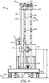
- FIG. 6 depicts the holder arm 120 in the service position.
- FIG. 5 depicts the holder arm 120 in an intermediate position between the ergonomic loading position and the service position.
- service position means the position of the holder arm 120 corresponding to actual operation of the filter holder 100 as a filtration system.
- the holder arm 120 When in the service position, the holder arm 120 is generally vertically oriented. However, the service position includes angular deviation from a vertical orientation, for example, in a range from about 75 degrees to about 105 degrees from horizontal or, more typically, from about 85 degrees to about 95 degrees from horizontal.
- the holder arm 120 is oriented orthogonal to the work surface W when in the service position.
- “ergonomic loading position” means the position of the holder arm 120 corresponding to loading or unloading of filter capsules 200 onto and from the holder arm 120.
- the holder arm 120 When in the ergonomic loading position, the holder arm 120 is generally horizontally oriented.
- the ergonomic loading position includes angular deviation from horizontal, for example, in a range from about -15 degrees to about +15 degrees from horizontal or, more typically, from about -5 degrees to about +5 degrees from horizontal.
- the ergonomic loading position is distinct from the service position.
- the ergonomic loading position is only applicable to embodiments where the holder arm 120 is tiltable to a service position and an ergonomic loading position.
- the holder arm 120 is oriented parallel to the work surface W when in the ergonomic loading position.
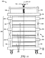
- Filter holders 100 may be provided with a holder arm 120 that is either (i) tiltable to a service position and an ergonomic loading position, or (ii) fixed in the service position (non-tiltable; see, e.g., FIGS. 11 and 13 ). Both configurations present advantages over known filter holders.
- filter holder 100 For example, operation of a filter holder 100 with a holder arm 120 in the service position allow for easier and more efficient venting of excess gas from the filter capsule stack 250 when the filter capsule stack 250 is being charged with a fluid before a filtering operation. Venting is easier because excess gas can escape upward through existing fluid connection ports positioned at the top of the filter capsule stack 250.
- Filter capsules 200 can be discarded after each use, thereby saving on process time and reducing or eliminating the cost of sanitizing agents.
- filter capsules 200 may be connected directly to one another in a filter capsule stack 250 without the need for bulky coupling plates in between capsules.
- the entire filter capsule stack 250 may be assembled more easily, with directly interfacing filter capsules 200 that may be discarded without the need to clean or handle coupling plates.
- the filter holder 100 can take up much less floor space than a unit that is fixed in a horizontal orientation. In other words, the filter holder 100 can have a substantially reduced footprint when in the service position.
- filter capsules 200 can still be cumbersome to load and unload while the holder arm 120 is in a service position. This difficulty can be amplified during unloading steps because the used filter capsules 200 often contain residual fluid that can make them much heavier.
- a filter compression adjustment 134 on such a fixed vertical unit may be located at the distal end 124 of the holder arm 120. This location may be above the reach of the operator. As such, the operator may need to climb a ladder or stool to adjust the filter compression adjustment 134.
- unloading filter capsules 200 from a vertical stack can result in leaking of residual fluid through ports in the bottom of each stacked filter capsule 200, as depicted in FIG. 8 .
- a fixed horizontal design may also be more difficult to purge or vent of excess gas while charging the system with a fluid. Because gravity causes fluid to pool at the bottom of the filter housings, any excess gas will collect at the top of the horizontally oriented filter housings. This means that separate venting plumbing must be provided along the "top" of the filter housings, in addition to the typical fluid ingress and egress provided within the heart of the housings. Such more complicated plumbing can mean, for example, more plumbing connections to be made and more potential locations where seals could fail.
- operation of a filter holder 100 with a holder arm 120 in the service position may be advantageous to operation in a fixed horizontal position.
- filter holders 100 comprising holder arms 120 that are tiltable to a service position and an ergonomic loading position enjoy all of the benefits described above with regard to those fixed in a service position, in addition to further benefits.
- filter capsules 200 can be loaded and unloaded from the holder arm 120 much more easily because the filter capsules are all presented to an operator at an ergonomic height where no bending over or climbing must be done. Tilting the holder arm is easily accomplished by a tilting mechanism 110 that is ergonomically placed for the convenience of the operator.
- the base 104 may comprise any form of structure adapted to support the weight of the filter holder 100 above a work surface W. It should be understood that the work surface W does not form a part of the filter holder 100, but is merely described to provide appropriate context for the features of the filter holder 100. As shown in FIGS. 1-6 and 11, base 104 comprises casters 106 that allow the filter holder 100 to be moved about the work surface W. The base 104 may further comprise lockable floor jacks 107 to lock the filter holder 100 into position on the work surface W and prevent it from rolling. It is also envisioned that the base 104 could be affixed to the work surface W.
- a mobile filter holder 100 may simply be wheeled in. loaded, and operated with less delay. For example, multiple rooms, each comprising large scale-up manufacturing fixtures, may simply be provided with appropriate plumbing connections to interface with a mobile filter holder 100 according to the present disclosure.
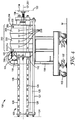
- the base 104 may comprise a pass-through side 105 (see, e.g., FIG. 3 ) to allow the base end 122 of the holder arm 120 to swing through and rest in the service position as close to the work surface W as possible.
- a pass-through side 105 see, e.g., FIG. 3
- Such a configuration allows for advantageous loading and operating conditions for the filter holder 100.
- the tilt axis 112 is preferably positioned at a comfortable height above the work surface W (a first distance A), to allow for easier loading and unloading of filter capsules 200 while the holder arm 120 is in the ergonomic loading position. Because the second distance B is effectively a radius for the swing of the base end 122 of holder arm 120, it is evident that if the second distance B were greater than the first distance A, the base end 122 would interfere with the work surface W while the holder arm 120 was tilting into the service position.
- the pass-through side 105 of the base 104 allows the holder arm 120 to swing through the base without interference.
- the pass-through side 105 can help to simultaneously allow (1) ergonomic positioning of the tilt axis 112 above the work surface W, and (2) increased capacity of the holder arm 120 to hold filter capsules 200.
- the tilting mechanism 110 where employed, is typically mounted on the base 104, as shown in FIG. 1 , and functions to tilt the holder arm 120 about the tilt axis 112. Because the holder arm 120 can be quite heavy when loaded with filter capsules 200, particularly when the filtration media is saturated with fluid, the tilting mechanism 110 must be capable of generating substantial torque about the tilt axis 112. This is particularly so when the center of gravity of the holder arm 120 is offset from the tilt axis 112 when the holder arm is in the ergonomic loading position. In such a condition, where a load is imbalanced about the tilt axis 112, there can be a substantial moment of force to be overcome to tilt the holder arm 120 upward and into the service position.
- the placement of the tilt axis 112, and (ii) the length of the holder arm 120 between the base end 122 and a distal end 124 can be optimized (e.g., maximizing the swing radius [the second distance B] of the holder arm 120, and further allowing for the loading as many filter capsules 200 onto the holder arm 120 as practical).
- the center of gravity of the holder arm 120 is substantially offset from the tilt axis 112 when the holder arm 120 is loaded with filter capsules 200.
- an exemplary filter holder 100 is shown wherein the holder arm 120 is tilted to an intermediate position between the service position and the ergonomic loading position.
- the holder arm 120 is shown here without a filter capsule stack 250 so that the underlying features of the filter holder are more clearly visible.
- the second distance B corresponds to a swing radius of the holder arm 120 as the base end 122 swings toward the work surface W.
- the base 104 comprises a pass-through side 105 (see, e.g., FIG. 3 ) through which the based end 122 passes on its way to the service position, as shown in FIG. 6 .
- the base end 122 of the holder arm 120 will clear the work surface W.
- the distance between the tilt axis 112 and the distal end 124 of the holder arm 120 is typically, though not necessarily, greater than the second distance B, as shown clearly in FIGS. 5 and 6 . This is because, while the based end 122 must clear the work surface W as it swings down while tilting, the distal end 124 is not so constrained. Therefore, so long as an overhead ceiling does not interfere with the distal end 124 as it swings into the service position, it may be desirable to increase the overall length of the holder arm 120 (the distance between the based end 122 and the distal end 124) to increase the number of filter capsules 200 that can be simultaneously loaded into the filter holder.
- substantially vertically aligned includes conditions of near-alignment.
- a vertical line drawn through such center of gravity while the holder arm 120 is in the service position may not exactly intersect with the tilt axis 112, but may be offset to either side of the tilt axis 112 by up to about 15 cm (about 6 inches), including about 2.5 cm (about 1 inch), 5.1 cm (2 inches), 7.6 cm (3 inches), 10.2 cm (4 inches), and even 12.7 cm (5 inches).
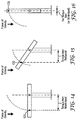
- FIGS. 14-16 depicting a simplified machine having an arm in various stages of tilting.
- the arm has a center of gravity ("CG") that is offset from the axis about which the arm tilts.
- CG center of gravity
- 14-16 is not necessarily representative of the actual location of the "CG" in a holder arm 120 according to the present disclosure, but rather is placed in the figures to demonstrate the general principle of reduction of gravity-induced torque about the tilt axis 112 as the holder arm 120 is tilted into the service position. It should also be understood that the location of the "CG" in an actual holder arm 120 will vary according to the construction of the holder arm 120, the number or size of filter capsules 200 loaded onto the holder arm 120, and the presence of residual fluid in the filter capsules 200.
- the tilting mechanism 110 comprises a gear box 111.
- a tilt shaft 113 at the tilt axis 112 is coupled, through the gear box 111, to a hand crank 114 operable to tilt the holder arm 120 to a service position and an ergonomic loading position.
- the tilting mechanism 110 could comprise a motor or be hydraulically operated. It may preferable, however, to avoid the need for electricity in the tilting mechanism 110, particularly where the filter holder 100 may be used in wet conditions or where working fluid may drip onto the filter holder 100.
- the holder arm 120 may be attached to a tilting mechanism 110 at a tilt axis 112, or it may be fixed to a base 104 in a vertical orientation.
- a tilting configuration can have a variety of advantages over a fixed vertical configuration. Nevertheless, fixed vertical configurations according to the present disclosure are an improvement over known filter holders.
- holder arm 120 comprises a base end 122 and a distal end 124 connected by a front support bar 126 and a rear support bar 128.
- at least one cradle bar 127 and optionally a load-bearing bar 125 disposed parallel to the front and rear support bars 126, 128 may further be employed.
- the holder arm 120 is coupled to the tilting mechanism by a holder bracket 115.
- front and rear are used herein only to clarify a relative position of one feature to another, and are not intended to limit the location of such features to any particular portion of the filter holder 100, or limit the filter holder 100 to any particular orientation.
- the front and rear support bars 126, 128 may be located on opposing sides of the filter holder 100, as clarified in FIGS. 11 and 13 .
- the at least one cradle bar 127 may provide support and alignment for a filter capsule 200 to keep the first axis 251 of the filter capsule stack 251 aligned with the holder arm axis 121, and at the same time prevent the filter capsule 200 from falling through the space between front and rear support bars 126, 128 while the holder arm 120 is in the ergonomic loading position.
- each filter capsule 200 may be configured with one or more alignment wings 203 to slidably engage one or more of the front and rear support bars 126, 128.
- Exemplary filter capsules 200 comprising two opposing alignment wings 203 are depicted in FIGS. 8 and 11 .
- An alignment wing 203 may comprise, for example, a semicircular bore corresponding to the diameter of front and/or rear support bars 126, 128 into which front and/or rear support bars 126, 128 can fit.
- FIG 11 placement of a filter capsule 200 having alignment wings 203 onto a holder arm 120, where opposing alignment wings 203 are fitted against front and rear support bars 126, 128, can assure that the first axis 251 of the filter capsule stack 251 is held in alignment with the holder arm axis 121.
- one or more cradle bars 127 may still be employed to, for example, provide improved rigidity to the holder arm 120.
- Front and rear support bars 126, 128 may each comprise a plurality of plate positioning grooves 129 distributed along their respective lengths.
- the plate positioning grooves 129 are spaced along the length of the front and rear support bars 126, 128 at intervals corresponding to the height of different configurations of filter capsule stacks 250 that may be loaded into the holder arm 120. Plate positioning grooves 129 may be clearly seen, for example, in FIGS. 1, 3-6, 11, and 13 .
- holder arm 120 comprises a compression plate 130 and a holding plate 140 disposed opposite the compression plate 130.
- One or more of the compression plate 130 or the holding plate 140 may be movable along the length of the front and rear support bars 126, 128.
- the holding plate 140 may be fixed upon the holder arm 120, while the compression plate 130 is movable.
- the compression plate 130 may be fixed upon the holder arm 120, while the holding plate 140 is movable.
- both the holding plate 140 and the compression plate 130 are movable.
- the holding plate 140 is typically movable incrementally to locations corresponding to the locations of plate positioning grooves 129, while the compression plate 130 is continuously adjustable over a smaller range to provide a compressive force to the filter capsule stack once the holding plate 140 has been moved into place. While the embodiment depicted in FIG. 1 depicts the compression plate 130 proximate the base end 122 of the holder arm 120, it is also envisioned that the compression plate 130 and the holding plate 140 may be flipped such that the holding plate 140 is proximate the base end 124, as shown in FIGS. 11 and 13 . In some embodiments, one or more of the holding plate 140 and the compression plate 130 are slidably connected to the front and rear support bars 126, 128. Slidable connection of the holding plate 140 or the compression plate 130 to the front and rear support bars 126, 128 may be accomplished by, for example, one or more linear bearings.
- the holding plate 140 may further comprise a locking bar 142 that is co-movable along the front and rear support bars 126, 128.
- the locking bar 142 can lock into a plate positioning groove 129 one or both of the front and rear support bars 126, 128, thereby positively locking the holding plate 140 into a pre-set position on the holder arm 120.
- the locking bar 142 is rotatable to a locked position and an unlocked position. In the locked position, the locking bar 142 may be simultaneously engaged in plate positioning grooves 129 on both front and rear support bars 126, 128. It is also envisioned that the holder plate 140 or the compression plate 130 may be lockable into one or more plate positioning grooves 129 without the provision of a separate locking bar 142.
- FIG. 1 further shows a filter compression adjustment 134 coupled to the compression plate 130. While shown here at the base end 122 of the holder arm 120, the filter compression adjustment may also be located at the distal end 124. Filter compression adjustment 134 adjusts the compression plate 130 along the front and rear support bars 126, 128 to apply compressive force to a filter capsule stack 250. Such an application of compression may be necessary because, for example, fluid to the filtered in the filter capsule stack 250 may be provided at elevated pressures, and the compressive contact of the holding plate 140 and the compression plate 130 against the ends of the filter capsule stack 254 can help to prevent deformation, separation, or rupture of the filter capsules 200.
- the filter compression adjustment 134 may comprise, for example a turnable acme screw or ball screw fixed at one point to the compression plate 130 and threadably coupled at another point to a member that is rigidly affixed to the holder arm.
- the filter compression adjustment 134 is provided with a torque limiter 138 to act as a proxy to limit the compressive force that can be applied to the filter capsule stack 250.
- the torque limiter 138 may be, for example, a friction-based or magnetic slip clutch. Provision of a torque limiter 138 may be advantageous, for example, when filter capsules 200 having fluid interconnects 208 and fluid seals as described in commonly owned U.S. Pat. App. No. 61/111,156 to Cashin et al. , entitled “Fluid Interconnect” (hereinafter "Cashin”) and U.S. Pat. App. No. 61/111,185 to Marks et al.
- the torque limiter 138 may be set to limit the torque applied by the filter compression adjustment 134, for example, to about 16 N ⁇ m (142 lb ⁇ in), 15 N ⁇ m (133 lb ⁇ in), 14 N ⁇ m (124 lb ⁇ in), 13 N ⁇ m (115 lb ⁇ in), 12 N ⁇ m (106 lb ⁇ in), 11 N ⁇ m (97 lb ⁇ in), 10 N ⁇ m (89 lb ⁇ in), 9 N ⁇ m (80 lb ⁇ in), 8 N ⁇ m (71 lb ⁇ in), 7 N ⁇ m (62 lb ⁇ in), 6 N ⁇ m (53 lb ⁇ in), or even to about 5 N ⁇ m (44 lb ⁇ in). Higher torque limits (or none at all) are envisioned where filter capsules 200 using face seals are employed.
- a torque limiter 138 on the filter compression adjustment 134 can provide further benefit to the operator by saving time and reducing the skill necessary to set-up a filter holder 100 to operate. For example, rather than having to incrementally tighten a filter capsule stack 250 and monitor compression force (perhaps via a gauge or load cell arrangement), an operator may simply adjust the filter compression adjustment 134 until the torque limiter 138 activates and further compressive force can no longer be applied to the filter capsule stack 250. Because this set up is so simple, the operator need not be trained on determining proper compression or reading gauge outputs.
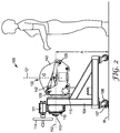
- FIG. 2 an operator is depicted standing in front of a filter holder 100 according to the present disclosure.
- the filter holder 100 shown comprises a holder arm 120 tiltable to a service position and an ergonomic loading position.
- the filter arm 120 is tilted to the ergonomic loading position.
- the holder arm 120 is positioned at a comfortable height to allow the operator to load and unload filter capsule 200. More particularly, in the embodiment shown, the first distance A from the work surface W to the tilt axis 112 corresponds roughl to waist height for the operator.
- the first distance A is in a range from about 71 cm (about 28 inches) to about 102 cm (about 40 inches), including, for example, each 2.54 cm (one-inch) increment within that range. Placement of the holder arm 120 at such a comfortable height while in the ergonomic loading position can allow an operator to load and unload filter capsules 200 in an ergonomically efficient way, without, for example, bending down or having to reach over their heads.
- the front support bar 126 is positioned slightly below the tilt axis 112, and also below the holder arm axis 121.
- the front support bar may be positioned in a range from about 2.54 cm (about 1 inch) to about 15 cm (about 6 inches) below the holder arm axis 121, including 2.54 cm (one-inch) increments within that range.
- This lowered positioning of the front support bar 126 allows filter capsules 200, which will be aligned with the holder arm axis 121, to be loaded or unloaded from the holder arm 120 with less lifting - i.e., the lower the front support bar 126 with respect to the holder arm axis 121, the shorter the distance each filter capsule 200 must be lifted in order to pass over it.
- the filter capsule 200 can be rotated toward the operator until the fulcrum lug 230 contacts against the lowered front support bar 126. See, e.g., FIGS. 3 and 9 .
- contact between the fulcrum lug 230 and the front support bar 126 causes the filter capsule 200 to pivot about the front support bar 126, giving the operator a larger lever arm, and therefore increased mechanical advantage in installing and removing the filter capsule 200 from the holder arm 120.
- the holder arm 120 is positioned roughly at waist level, used filter capsules 200 may be conveniently rolled off of the holder arm 120 directly into a waste receptacle (not shown).
- a further advantage of unloading of used filter capsules 200 while the holder arm 120 is in the ergonomic loading position is the containment of residual fluid in the used filter capsule 200.
- the interior of the filter capsules 200 becomes filled and saturated with fluid.
- removal of a filter capsule 200 while on its side ( i.e., while the holder arm is in the ergonomic loading position) as in FIG. 7 is advantageous because residual fluid is contained within the filter capsule 200.
- the filter capsule 200 unloaded in a vertical position as shown in FIG. 8 can leak residual fluid because the exposed fluid port is oriented on the bottom of the filter capsule 200.
- the hand crank 114 on the tilting mechanism 110 is also placed at a convenient height for the operator, as are the holding plate 140, the locking bar 142, the compression plate 130 (not visible), and the filter compression adjustment 134 (not visible). Accordingly, in the embodiment shown, when the holder arm 120 is in the ergonomic loading position, all features that must be routinely accessed by the operator are positioned at a convenient, ergonomic height.
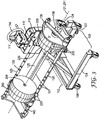
- FIG. 4 depicts a filter holder 100 in the ergonomic loading position wherein the holder arm 120 is loaded with a filter capsule stack 250 comprising two filter capsules 200 sandwiched between two manifold members 280.
- the manifold members may optionally comprise one or more of a feed fluid ingress 210 or a filtrate egress 214.
- the filter capsule stack 250 is compressed between the compression plate 130 and the holding plate 140.
- Exemplary filter capsule stacks 250 can be seen, for example, in FIGS. 4,10, and 11-12 . It can also be clearly seen in the embodiment shown in FIGS. 2 and 4 that the front support bar 126 is positioned below the holder arm axis 121 to promote easier loading and unloading of filter capsules 200, as described above.
- the holding plate 140 has been positioned along front and rear support bars 126, 128 to contact the filter capsule stack 250, with the locking bar 142 shown engaged in a plate positioning groove 129 in the front support bar 126 to lock the holding plate 140 into position on the holder arm 120.
- FIG. 10 depicts one embodiment of a filter capsule stack 250 according to the present disclosure.
- the filter capsule stack 250 depicted in FIG. 10 comprises three filter capsules 200 connected to one another by a fluid interconnect 208. While FIG. 10 depicts a fluid interconnect 208 that can advantageously employ a piston seal as described in Cashin, it is also envisioned that adjacent filter capsules 200 may fluidly connect to one another by way of a simple face seal, or a combination of piston seals and face seals. In embodiments where a face seal is employed, compression of the filter capsule stack 250 acts to engage and compress a face sealing member between filter capsules 200, thereby fluidly sealing each filter capsule 200 to an adjacent filter capsule 200.
- Each filter capsule 200 can comprise one or more filter elements 202 disposed therein.
- each filter capsule 200 comprises a different type of filter element 202.
- each filter capsule 200 may comprise a filter element 202 for one of, for example, depth filtration, scale reduction, antimicrobial treatment, antiviral treatment, flavor enhancement, or others.
- Such filter elements 202 may be used alone or in combination with other filter elements 202. In this way, the filter capsule stack 250 may be customized to provide application-specific filtration.
- a filter capsule stack 250 having either (i) both a feed fluid ingress 210 and a filtrate egress 214 located on a single end of the filter capsule stack 250, or (ii) a feed fluid ingress 210 on one end and a filtrate egress 214 on the opposing end. Locating a feed fluid ingress 210 and a filtrate egress 214 located on a single end allows associated plumbing to be located in a single area, rather than being separated by the length of the filter capsule stack 250. The result can be a more compact assembly.
- the filter capsule stack 250 may comprise one or more manifold members 280, as depicted in FIG. 12 . As shown in FIG.
- the purpose of the manifold member 280 when employed, is to direct fluid flow at a terminal end of the filter capsule stack 250.
- the manifold member 280 can operate as a dead-end for filtrate, allowing the filtrate to reverse direction and travel back toward the filtrate egress 214 to exit the filter capsule stack 250.
- the manifold member 280 may also provide both fluid ingress 210 and filtrate egress 214 on a single end of the filter capsule stack 250.
- the manifold member 280 may, more simply, provide only feed fluid ingress 210 or only filtrate egress 214. Combinations of these embodiments are also envisioned. For example, flow configuration as described above may be utilized to achieve series or parallel filtration - e.g., one filter capsule 200 either in series or in parallel with an adjacent filter capsule 200. Such flow configurations may also be combined in a single filter capsule stack 250 so that certain filter capsules 200 are operated in parallel, while others are operated in series.
- the manifold member 280 may be constructed of, for example, polycarbonate or polypropylene.
- FIG. 12 depicts a filter capsule stack 250 arranged such that dirty fluid "D" flows in through the top of the filter capsule stack and clean fluid “C” flows out through the bottom.
- inlet and outlet flow may be configured in multiple ways.
- both feed fluid ingress 210 and filtrate egress 214 occur within a single manifold member 280 positioned at the bottom of the filter capsule stack 250, while only venting of excess gas occurs through a manifold member 280 positioned at the top of the filter capsule stack 250.
- the filter capsule stack 250 is typically positioned in a holder arm 120 of a filter holder 100 during operation, as shown in FIG. 11 .
- a holder arm 120 comprising a compression plate 130 and an opposing holder plate 140 may be required, for example, to hold the end walls of the outer-most located filter capsules 200 in a filter capsule stack 250. Because such outer-most located end walls are not supported against an adjacent filter capsule 200, contact with the compression plate 130 or the holder plate 140 can help to prevent wall flexure under internal fluid pressure.
- the filter holder 100 can apply force, along the direction of a first axis 251 of the filter capsule stack 250 (typically aligned with the holder arm axis 121), to the compression plate 130 and the holder plate 140.
- the compression plate 130 and the holder plate 140 bear against a filter capsule 200 at one or the other end of the filter capsule stack 250.
- each filter capsule 200 in the filter capsule stack 250 contacts an adjacent filter capsule 200 at a bearing point, thus providing a known, rigid datum upon which to apply force.
- the filter holder 100 may further provide apparatus for feed fluid ingress 210 and filtrate egress 214.
- parts of the filter holder 100 may be constructed of, for example, stainless steel.
- filter holders 100 are typically loaded with one or more filter capsules 200, optionally including one or more manifold members 280, to form a filter capsule stack 250 on the holder arm 120.
- the filter capsule stack 250 is compressed between a holding plate 140 and a compression plate 130.
- the filter holder is then operated as a filtration system in the service position.
- loading a filter capsule 200 onto the holder arm 120 comprises fitting an alignment wing 203 of a filter capsule against one of the front or rear support bars 126, 128 to align the first axis 251 of the filter capsule stack 250 with the holder arm axis 121.
- the filter holder 100 comprises a holder arm 120 attached to a tilting mechanism at a tilt axis 112
- the holder arm 120 is typically tilted to an ergonomic loading position and loaded with one or more filter capsules 200, optionally including one or more manifold members 280, to form a filter capsule stack 250 on the holder arm 120.
- the holder arm 120 is then tilted to a service position where the filter holder may be operated as a filtration system.
- operating the filter holder as a filtration system comprises one or more of charging the filter capsule stack 250 with a fluid, purging the filter capsule stack 250 of excess gas, filtering the fluid through a filter capsule 200, and discharging residual fluid from the filter capsule stack 250.
- the filter arm 120 may be tilted by way of an operator turning a hand crank 114 coupled through a gear box 111 to a tilt shaft 113 at a tilt axis 112.
- the method of operating the filter holder 100 may further comprise the filter capsule stack 250 being compressed between a holding plate140 and a compression plate 130.
- the holding plate is locked in place to prevent it from sliding.
- locking is accomplished by a locking bar 142 that engages with a plate positioning groove 129 on one or more of the front and rear support bars 126, 128.
- the method further comprises adjusting the compression of the filter capsule stack 250 between the holding plate 140 and the compression plate 130. In some examples, this is done by an operator adjusting a filter compression adjustment 134. In one example, the operator adjusts the filter compression adjustment 134 by increasing the compression of the filter capsule stack 250 until a torque limiter 138 activates to limit further compression. As described above, depending on the type and quantity of filter capsules 200 used in the filter capsule stack 250, the torque limit of the torque limiter 138 may be set to any appropriate torque, including an advantageous lower torque limit when filter capsules according to Cashin are employed.
- the method further comprises tilting the holder arm 120 from the service position back to the ergonomic loading position.
- tilting the holder arm 120 from the service position to the ergonomic loading position is done by reversing the steps described above for tilting the holder arm 120 into the service position.
- the method may further comprise unloading the filter capsule stack 250 from the holder arm 120.
- each filter capsule 200 is disengaged from an adjacent filter capsule 200 by holding the adjacent filter capsule 200 while rotating the filter capsule 200 to be removed toward the operator. In performing this step, very little lateral motion is required of the operator. Rather, the operator need only rotate the filter capsule 200 toward the operator's body and gently lift the filter capsule 200 out of the holder arm.
- unloading the filter capsule stack 250 from the holder arm 120 comprises rotating a filter capsule 200 over a front support bar 126.
- rotating the filter capsule 200 over a front support bar 126 may comprise engaging the fulcrum lug 230 against the front support bar 126 and rotating the filter capsule 200 about the fulcrum lug 230 to roll the filter capsule 200 over the front support bar 126.
- the handle may be grasped by the operator to assist in rotating the filter capsule toward the operator, and also in holding the adjacent filter capsule 200 to prevent it from rotating while disengaging one filter capsule 200 from another.
- Handles 204 are clearly shown, for example, in FIGS. 9 and 10 .
- the method may include grasping the handle 204 of a filter capsule 200 to lift the filter capsule 200 onto or off of the holder arm 120.
- the method includes tilting the holder arm 120 from a position where the center of gravity of the holder arm 120 is vertically misaligned from the tilt axis 112 into a position where the center of gravity of the holder arm 120 is substantially vertically aligned with the tilt axis 112.
Claims (11)
- Porte-filtre (100) pour une pile de capsules de filtrage, le porte-filtre (100) comprenant : une base (104) destinée à soutenir le porte-filtre (100) sur une surface de travail (W) ;
un mécanisme d'inclinaison (110) fixé à la base (104) ; et
un bras de support (120) fixé au mécanisme d'inclinaison (110) au niveau d'un axe d'inclinaison (112), le bras de support (120) comprenant : une extrémité de base (122), une plaque de compression (130) à proximité de l'extrémité de base (122), une extrémité distale (124), une plaque de maintien (140) à proximité de l'extrémité distale (124), une barre de support avant (126), et une barre de support arrière (128), la plaque de maintien (140) étant reliée de manière coulissante à la barre de support avant (126) et à la barre de support arrière (128), et le bras de support étant inclinable autour de l'axe d'inclinaison (112) à une position de service et une position de chargement ergonomique ;
dans lequel, lors de l'installation, la pile de capsules de filtrage est maintenue entre la plaque de compression (130) et la plaque de maintien (140) ; et
dans lequel la plaque de compression (130) est réglable en continu par un réglage de compression de filtre (134), qui est couplé à la plaque de compression (130). - Porte-filtre selon la revendication 1, dans lequel le réglage de compression de filtre (134) comprend un limiteur de couple (138).
- Porte-filtre selon la revendication 2, dans lequel la limite de couple est inférieure à environ 12 N·m.
- Porte-filtre selon la revendication 1, dans lequel l'axe d'inclinaison (112) est situé à une première distance (A) de la surface de travail (W) et l'extrémité de base (122) du bras de support (120) est située à une deuxième distance (B) de l'axe d'inclinaison (112), la deuxième distance (B) étant inférieure à la première distance (A).
- Porte-filtre selon la revendication 1, dans lequel la plaque de compression (130) est reliée d'une manière coulissante à la barre de support avant (126) et à la barre de support arrière (128).
- Porte-filtre selon la revendication 1, dans lequel la barre de support avant (126) et la barre de support arrière (128) comprennent chacune une pluralité de rainures de positionnement de plaque (129).
- Porte-filtre selon la revendication 1, dans lequel, lorsque le bras de support (120) est dans la position de chargement ergonomique, la barre de support avant (126) est positionnée en dessous de l'axe d'inclinaison (112), et la barre de support arrière (128) est positionnée au niveau ou au-dessus de l'axe d'inclinaison (112).
- Porte-filtre selon la revendication 1, dans lequel, lorsqu'il est dans la position de service, le bras de support (120) est orienté orthogonal à la surface de travail (W) et, lorsqu'il est dans la position de chargement ergonomique, le bras de support (120) est orienté parallèle à la surface de travail (W).
- Porte-filtre selon la revendication 1, dans lequel l'axe d'inclinaison (112) est situé à une première distance (A) de la surface de travail (W), la première distance (A) étant dans une plage allant d'environ 71 cm (environ 28 pouces) à environ 102 cm (environ 40 pouces).
- Porte-filtre selon la revendication 1, dans lequel, lorsque le bras de support (120) est dans la position de chargement ergonomique, le centre de gravité (CG) du bras de support (120) n'est pas aligné verticalement sur l'axe d'inclinaison (112) et, lorsque le bras de support (120) est dans la position de service, le centre de gravité (CG) du bras de support (120) est aligné de façon essentiellement verticale sur l'axe d'inclinaison (112).
- Système de filtre comprenant le porte-filtre selon la revendication 1 et une pile de capsules de filtrage chargée sur le bras de support, dans lequel, lorsque le bras de support (120) est dans la position de chargement ergonomique, le centre de gravité (CG) du bras de support (120) chargé avec la pile de capsules de filtrage (250) n'est pas aligné verticalement sur l'axe d'inclinaison (112) et, lorsque le bras de support (120) est dans la position de service, le centre de gravité (CG) du bras de support (120) chargé avec la pile de capsules de filtrage (250) est aligné de façon essentiellement verticale sur l'axe d'inclinaison (112).
Applications Claiming Priority (2)
| Application Number | Priority Date | Filing Date | Title |
|---|---|---|---|
| US25664309P | 2009-10-30 | 2009-10-30 | |
| PCT/US2010/054217 WO2011053623A2 (fr) | 2009-10-30 | 2010-10-27 | Dispositif filtrant et procédé d'utilisation |
Publications (2)
| Publication Number | Publication Date |
|---|---|
| EP2493588A2 EP2493588A2 (fr) | 2012-09-05 |
| EP2493588B1 true EP2493588B1 (fr) | 2016-04-06 |
Family
ID=43252061
Family Applications (1)
| Application Number | Title | Priority Date | Filing Date |
|---|---|---|---|
| EP10773802.3A Active EP2493588B1 (fr) | 2009-10-30 | 2010-10-27 | Dispositif filtrant |
Country Status (7)
| Country | Link |
|---|---|
| US (1) | US9242193B2 (fr) |
| EP (1) | EP2493588B1 (fr) |
| JP (1) | JP5809156B2 (fr) |
| CN (1) | CN102639204B (fr) |
| BR (1) | BR112012010147B8 (fr) |
| TW (1) | TWI559968B (fr) |
| WO (1) | WO2011053623A2 (fr) |
Families Citing this family (5)
| Publication number | Priority date | Publication date | Assignee | Title |
|---|---|---|---|---|
| BR112014006464A2 (pt) * | 2011-09-19 | 2017-03-28 | 3M Innovative Properties Co | aparelho de filtro de indexação e método de uso |
| WO2013102165A2 (fr) * | 2011-12-29 | 2013-07-04 | Delcath Systems, Inc. | Appareil filtrant réglable |
| EP3456399B1 (fr) | 2017-09-19 | 2020-08-19 | Sartorius Stedim Biotech GmbH | Patin de filtre avec mécanisme de basculement |
| CO2019012051A1 (es) * | 2019-10-29 | 2020-01-17 | Esenttia S A | Dispositivo portatil para cambiar portamallas de los filtros de polímeros en peletizadoras |
| WO2023079423A1 (fr) * | 2021-11-04 | 2023-05-11 | 3M Innovative Properties Company | Appareil de filtration |
Citations (1)
| Publication number | Priority date | Publication date | Assignee | Title |
|---|---|---|---|---|
| DE3005310A1 (de) * | 1980-01-14 | 1981-07-23 | Buitendijk-Techniek B.V., Zwijndrecht | Vorrichtung zum abstuetzen und verstellen zu bearbeitender werkstuecke |
Family Cites Families (21)
| Publication number | Priority date | Publication date | Assignee | Title |
|---|---|---|---|---|
| GB190208392A (en) * | 1902-04-10 | 1902-06-12 | John Gibson Crossman | Improvements in Filter and Extractor Presses. |
| DE343144C (de) | 1916-06-24 | 1921-10-28 | United Filters Corp | Druckfilter |
| US2183951A (en) * | 1938-02-14 | 1939-12-19 | Fibreboard Products Inc | Carton assembling machine |
| US3494467A (en) | 1968-04-03 | 1970-02-10 | Douglas A Paisley | Horizontal leaf dry cake discharge filter |
| US3928008A (en) * | 1974-08-05 | 1975-12-23 | Ross K Petersen | Filtering apparatus |
| DE3240102A1 (de) | 1982-10-29 | 1984-05-03 | Karl W. 5064 Rösrath Loeffler | Filtervorrichtung |
| JPS60193511A (ja) | 1984-03-14 | 1985-10-02 | Ngk Insulators Ltd | フイルタ−プレスのケ−キ離脱装置 |
| IT1197000B (it) | 1986-07-25 | 1988-11-25 | Chimica Larderello Spa Soc | Procedimento per la produzione di tetraborato di sodio pentaidrato |
| JPH0248771Y2 (fr) * | 1986-08-27 | 1990-12-20 | ||
| TW293076B (en) | 1996-07-19 | 1996-12-11 | Mos Electronics Taiwan Inc | The deionized water transported piping of wafer scrubber |
| JPH10317120A (ja) | 1997-05-23 | 1998-12-02 | Sumitomo Metal Ind Ltd | 溶融亜鉛めっきにおけるトップドロス回収装置 |
| JP2003509186A (ja) | 1999-09-17 | 2003-03-11 | マイクロリス・コーポレイシヨン | スラリーを濾過するためのフィルタカートリッジ |
| FR2822720B1 (fr) | 2001-03-28 | 2004-01-09 | Sarl Vallet Pharma | Dispositif de filtration et de sechage de particules solides en suspension dans un solvant |
| JP4248464B2 (ja) | 2004-08-25 | 2009-04-02 | 日機装株式会社 | フィルタホルダ |
| TWM293076U (en) * | 2006-02-24 | 2006-07-01 | Tai Ho Environmental Entpr Co | Separating apparatus for filter plate of filter pressing device |
| JP2007307509A (ja) * | 2006-05-19 | 2007-11-29 | Eco Creative Japan:Kk | 水処理装置 |
| US10918985B2 (en) | 2008-11-04 | 2021-02-16 | 3M Innovative Properties Company | Filter element and seal therefor |
| WO2010053903A2 (fr) | 2008-11-04 | 2010-05-14 | 3M Innovative Properties Company | Interconnexion pour fluide |
| JP2010207719A (ja) | 2009-03-10 | 2010-09-24 | Denso Wave Inc | 産業機器のコントローラ |
| CN109477418B (zh) | 2016-08-24 | 2021-01-26 | 株式会社Ihi | 可变容量型增压器 |
| JP7258629B2 (ja) | 2019-03-29 | 2023-04-17 | キヤノン株式会社 | 撮像装置、撮像システム、および撮像装置の駆動方法 |
-
2010
- 2010-10-27 JP JP2012536983A patent/JP5809156B2/ja not_active Expired - Fee Related
- 2010-10-27 CN CN201080054187.3A patent/CN102639204B/zh active Active
- 2010-10-27 WO PCT/US2010/054217 patent/WO2011053623A2/fr active Application Filing
- 2010-10-27 EP EP10773802.3A patent/EP2493588B1/fr active Active
- 2010-10-27 US US13/504,161 patent/US9242193B2/en active Active
- 2010-10-27 BR BR112012010147A patent/BR112012010147B8/pt active IP Right Grant
- 2010-10-29 TW TW099137367A patent/TWI559968B/zh not_active IP Right Cessation
Patent Citations (1)
| Publication number | Priority date | Publication date | Assignee | Title |
|---|---|---|---|---|
| DE3005310A1 (de) * | 1980-01-14 | 1981-07-23 | Buitendijk-Techniek B.V., Zwijndrecht | Vorrichtung zum abstuetzen und verstellen zu bearbeitender werkstuecke |
Also Published As
| Publication number | Publication date |
|---|---|
| US20120279915A1 (en) | 2012-11-08 |
| US9242193B2 (en) | 2016-01-26 |
| BR112012010147B8 (pt) | 2021-05-11 |
| BR112012010147A2 (pt) | 2020-08-18 |
| CN102639204B (zh) | 2015-01-21 |
| EP2493588A2 (fr) | 2012-09-05 |
| BR112012010147A8 (pt) | 2021-01-26 |
| JP5809156B2 (ja) | 2015-11-10 |
| TW201138927A (en) | 2011-11-16 |
| BR112012010147B1 (pt) | 2021-03-02 |
| WO2011053623A3 (fr) | 2011-08-18 |
| WO2011053623A2 (fr) | 2011-05-05 |
| JP2013509294A (ja) | 2013-03-14 |
| CN102639204A (zh) | 2012-08-15 |
| TWI559968B (en) | 2016-12-01 |
Similar Documents
| Publication | Publication Date | Title |
|---|---|---|
| EP2493588B1 (fr) | Dispositif filtrant | |
| US9616365B2 (en) | Indexing filter apparatus and method of use | |
| US6207051B1 (en) | Filtered hydraulic fluid handling system | |
| US20180055302A1 (en) | Surface cleaning apparatus | |
| CN113951724A (zh) | 饮品机 | |
| WO2023079423A1 (fr) | Appareil de filtration | |
| JP2002522326A (ja) | ディスクスタック輸送用リフト装置 | |
| CN113702110B (zh) | 一种可调节深度的液体食品检测用取液设备 | |
| CN107461587A (zh) | 一种个人计算机显示屏支撑结构 | |
| KR101137945B1 (ko) | 필터교체장치 | |
| EP3080600B1 (fr) | Piston et colonne de traitement | |
| US10441125B2 (en) | Surface cleaning apparatus | |
| US9962050B2 (en) | Surface cleaning apparatus | |
| CN107998703A (zh) | 一种直立式压滤机 | |
| CN114180196A (zh) | 一种医学检验科样本转运装置 | |
| US20050279716A1 (en) | Water filter module handling apparatus | |
| CN214076802U (zh) | 一种稳固性好的医疗检验科用试管架 | |
| CN217642732U (zh) | 一种一体化电容器补偿装置 | |
| CN213885079U (zh) | 一种植物提取蒸馏物分层分离装置 | |
| CN213667161U (zh) | 一种血液净化废液存储装置 | |
| CN214929986U (zh) | 一种农业用集水箱搬运装置 | |
| CN215654198U (zh) | 一种滤水器反冲洗装置 | |
| CN211443759U (zh) | 一种物理教学设备搬运架 | |
| CN220824846U (zh) | 固定容量瓶式托盘 | |
| CN210278066U (zh) | 一种消防用集水器 |
Legal Events
| Date | Code | Title | Description |
|---|---|---|---|
| PUAI | Public reference made under article 153(3) epc to a published international application that has entered the european phase |
Free format text: ORIGINAL CODE: 0009012 |
|
| 17P | Request for examination filed |
Effective date: 20120507 |
|
| AK | Designated contracting states |
Kind code of ref document: A2 Designated state(s): AL AT BE BG CH CY CZ DE DK EE ES FI FR GB GR HR HU IE IS IT LI LT LU LV MC MK MT NL NO PL PT RO RS SE SI SK SM TR |
|
| DAX | Request for extension of the european patent (deleted) | ||
| 17Q | First examination report despatched |
Effective date: 20130725 |
|
| GRAP | Despatch of communication of intention to grant a patent |
Free format text: ORIGINAL CODE: EPIDOSNIGR1 |
|
| INTG | Intention to grant announced |
Effective date: 20151001 |
|
| GRAS | Grant fee paid |
Free format text: ORIGINAL CODE: EPIDOSNIGR3 |
|
| GRAA | (expected) grant |
Free format text: ORIGINAL CODE: 0009210 |
|
| AK | Designated contracting states |
Kind code of ref document: B1 Designated state(s): AL AT BE BG CH CY CZ DE DK EE ES FI FR GB GR HR HU IE IS IT LI LT LU LV MC MK MT NL NO PL PT RO RS SE SI SK SM TR |
|
| REG | Reference to a national code |
Ref country code: GB Ref legal event code: FG4D |
|
| REG | Reference to a national code |
Ref country code: AT Ref legal event code: REF Ref document number: 787105 Country of ref document: AT Kind code of ref document: T Effective date: 20160415 Ref country code: CH Ref legal event code: EP |
|
| REG | Reference to a national code |
Ref country code: IE Ref legal event code: FG4D |
|
| REG | Reference to a national code |
Ref country code: DE Ref legal event code: R096 Ref document number: 602010032078 Country of ref document: DE |
|
| REG | Reference to a national code |
Ref country code: LT Ref legal event code: MG4D Ref country code: NL Ref legal event code: MP Effective date: 20160406 |
|
| REG | Reference to a national code |
Ref country code: AT Ref legal event code: MK05 Ref document number: 787105 Country of ref document: AT Kind code of ref document: T Effective date: 20160406 |
|
| PG25 | Lapsed in a contracting state [announced via postgrant information from national office to epo] |
Ref country code: NL Free format text: LAPSE BECAUSE OF FAILURE TO SUBMIT A TRANSLATION OF THE DESCRIPTION OR TO PAY THE FEE WITHIN THE PRESCRIBED TIME-LIMIT Effective date: 20160406 |
|
| PG25 | Lapsed in a contracting state [announced via postgrant information from national office to epo] |
Ref country code: LT Free format text: LAPSE BECAUSE OF FAILURE TO SUBMIT A TRANSLATION OF THE DESCRIPTION OR TO PAY THE FEE WITHIN THE PRESCRIBED TIME-LIMIT Effective date: 20160406 Ref country code: IS Free format text: LAPSE BECAUSE OF FAILURE TO SUBMIT A TRANSLATION OF THE DESCRIPTION OR TO PAY THE FEE WITHIN THE PRESCRIBED TIME-LIMIT Effective date: 20160806 Ref country code: NO Free format text: LAPSE BECAUSE OF FAILURE TO SUBMIT A TRANSLATION OF THE DESCRIPTION OR TO PAY THE FEE WITHIN THE PRESCRIBED TIME-LIMIT Effective date: 20160706 Ref country code: FI Free format text: LAPSE BECAUSE OF FAILURE TO SUBMIT A TRANSLATION OF THE DESCRIPTION OR TO PAY THE FEE WITHIN THE PRESCRIBED TIME-LIMIT Effective date: 20160406 Ref country code: PL Free format text: LAPSE BECAUSE OF FAILURE TO SUBMIT A TRANSLATION OF THE DESCRIPTION OR TO PAY THE FEE WITHIN THE PRESCRIBED TIME-LIMIT Effective date: 20160406 |
|
| PG25 | Lapsed in a contracting state [announced via postgrant information from national office to epo] |
Ref country code: GR Free format text: LAPSE BECAUSE OF FAILURE TO SUBMIT A TRANSLATION OF THE DESCRIPTION OR TO PAY THE FEE WITHIN THE PRESCRIBED TIME-LIMIT Effective date: 20160707 Ref country code: SE Free format text: LAPSE BECAUSE OF FAILURE TO SUBMIT A TRANSLATION OF THE DESCRIPTION OR TO PAY THE FEE WITHIN THE PRESCRIBED TIME-LIMIT Effective date: 20160406 Ref country code: HR Free format text: LAPSE BECAUSE OF FAILURE TO SUBMIT A TRANSLATION OF THE DESCRIPTION OR TO PAY THE FEE WITHIN THE PRESCRIBED TIME-LIMIT Effective date: 20160406 Ref country code: LV Free format text: LAPSE BECAUSE OF FAILURE TO SUBMIT A TRANSLATION OF THE DESCRIPTION OR TO PAY THE FEE WITHIN THE PRESCRIBED TIME-LIMIT Effective date: 20160406 Ref country code: PT Free format text: LAPSE BECAUSE OF FAILURE TO SUBMIT A TRANSLATION OF THE DESCRIPTION OR TO PAY THE FEE WITHIN THE PRESCRIBED TIME-LIMIT Effective date: 20160808 Ref country code: ES Free format text: LAPSE BECAUSE OF FAILURE TO SUBMIT A TRANSLATION OF THE DESCRIPTION OR TO PAY THE FEE WITHIN THE PRESCRIBED TIME-LIMIT Effective date: 20160406 Ref country code: RS Free format text: LAPSE BECAUSE OF FAILURE TO SUBMIT A TRANSLATION OF THE DESCRIPTION OR TO PAY THE FEE WITHIN THE PRESCRIBED TIME-LIMIT Effective date: 20160406 Ref country code: AT Free format text: LAPSE BECAUSE OF FAILURE TO SUBMIT A TRANSLATION OF THE DESCRIPTION OR TO PAY THE FEE WITHIN THE PRESCRIBED TIME-LIMIT Effective date: 20160406 |
|
| PG25 | Lapsed in a contracting state [announced via postgrant information from national office to epo] |
Ref country code: IT Free format text: LAPSE BECAUSE OF FAILURE TO SUBMIT A TRANSLATION OF THE DESCRIPTION OR TO PAY THE FEE WITHIN THE PRESCRIBED TIME-LIMIT Effective date: 20160406 Ref country code: BE Free format text: LAPSE BECAUSE OF FAILURE TO SUBMIT A TRANSLATION OF THE DESCRIPTION OR TO PAY THE FEE WITHIN THE PRESCRIBED TIME-LIMIT Effective date: 20160406 |
|
| REG | Reference to a national code |
Ref country code: DE Ref legal event code: R097 Ref document number: 602010032078 Country of ref document: DE |
|
| PG25 | Lapsed in a contracting state [announced via postgrant information from national office to epo] |
Ref country code: CZ Free format text: LAPSE BECAUSE OF FAILURE TO SUBMIT A TRANSLATION OF THE DESCRIPTION OR TO PAY THE FEE WITHIN THE PRESCRIBED TIME-LIMIT Effective date: 20160406 Ref country code: EE Free format text: LAPSE BECAUSE OF FAILURE TO SUBMIT A TRANSLATION OF THE DESCRIPTION OR TO PAY THE FEE WITHIN THE PRESCRIBED TIME-LIMIT Effective date: 20160406 Ref country code: SK Free format text: LAPSE BECAUSE OF FAILURE TO SUBMIT A TRANSLATION OF THE DESCRIPTION OR TO PAY THE FEE WITHIN THE PRESCRIBED TIME-LIMIT Effective date: 20160406 Ref country code: RO Free format text: LAPSE BECAUSE OF FAILURE TO SUBMIT A TRANSLATION OF THE DESCRIPTION OR TO PAY THE FEE WITHIN THE PRESCRIBED TIME-LIMIT Effective date: 20160406 Ref country code: DK Free format text: LAPSE BECAUSE OF FAILURE TO SUBMIT A TRANSLATION OF THE DESCRIPTION OR TO PAY THE FEE WITHIN THE PRESCRIBED TIME-LIMIT Effective date: 20160406 |
|
| PLBE | No opposition filed within time limit |
Free format text: ORIGINAL CODE: 0009261 |
|
| STAA | Information on the status of an ep patent application or granted ep patent |
Free format text: STATUS: NO OPPOSITION FILED WITHIN TIME LIMIT |
|
| PG25 | Lapsed in a contracting state [announced via postgrant information from national office to epo] |
Ref country code: SM Free format text: LAPSE BECAUSE OF FAILURE TO SUBMIT A TRANSLATION OF THE DESCRIPTION OR TO PAY THE FEE WITHIN THE PRESCRIBED TIME-LIMIT Effective date: 20160406 |
|
| 26N | No opposition filed |
Effective date: 20170110 |
|
| PG25 | Lapsed in a contracting state [announced via postgrant information from national office to epo] |
Ref country code: SI Free format text: LAPSE BECAUSE OF FAILURE TO SUBMIT A TRANSLATION OF THE DESCRIPTION OR TO PAY THE FEE WITHIN THE PRESCRIBED TIME-LIMIT Effective date: 20160406 |
|
| REG | Reference to a national code |
Ref country code: CH Ref legal event code: PL |
|
| GBPC | Gb: european patent ceased through non-payment of renewal fee |
Effective date: 20161027 |
|
| REG | Reference to a national code |
Ref country code: IE Ref legal event code: MM4A |
|
| REG | Reference to a national code |
Ref country code: FR Ref legal event code: ST Effective date: 20170630 |
|
| PG25 | Lapsed in a contracting state [announced via postgrant information from national office to epo] |
Ref country code: CH Free format text: LAPSE BECAUSE OF NON-PAYMENT OF DUE FEES Effective date: 20161031 Ref country code: FR Free format text: LAPSE BECAUSE OF NON-PAYMENT OF DUE FEES Effective date: 20161102 Ref country code: GB Free format text: LAPSE BECAUSE OF NON-PAYMENT OF DUE FEES Effective date: 20161027 Ref country code: LI Free format text: LAPSE BECAUSE OF NON-PAYMENT OF DUE FEES Effective date: 20161031 |
|
| PG25 | Lapsed in a contracting state [announced via postgrant information from national office to epo] |
Ref country code: LU Free format text: LAPSE BECAUSE OF NON-PAYMENT OF DUE FEES Effective date: 20161027 |
|
| PG25 | Lapsed in a contracting state [announced via postgrant information from national office to epo] |
Ref country code: IE Free format text: LAPSE BECAUSE OF NON-PAYMENT OF DUE FEES Effective date: 20161027 |
|
| PG25 | Lapsed in a contracting state [announced via postgrant information from national office to epo] |
Ref country code: HU Free format text: LAPSE BECAUSE OF FAILURE TO SUBMIT A TRANSLATION OF THE DESCRIPTION OR TO PAY THE FEE WITHIN THE PRESCRIBED TIME-LIMIT; INVALID AB INITIO Effective date: 20101027 Ref country code: CY Free format text: LAPSE BECAUSE OF FAILURE TO SUBMIT A TRANSLATION OF THE DESCRIPTION OR TO PAY THE FEE WITHIN THE PRESCRIBED TIME-LIMIT Effective date: 20160406 |
|
| PG25 | Lapsed in a contracting state [announced via postgrant information from national office to epo] |
Ref country code: MK Free format text: LAPSE BECAUSE OF FAILURE TO SUBMIT A TRANSLATION OF THE DESCRIPTION OR TO PAY THE FEE WITHIN THE PRESCRIBED TIME-LIMIT Effective date: 20160406 Ref country code: TR Free format text: LAPSE BECAUSE OF FAILURE TO SUBMIT A TRANSLATION OF THE DESCRIPTION OR TO PAY THE FEE WITHIN THE PRESCRIBED TIME-LIMIT Effective date: 20160406 Ref country code: MT Free format text: LAPSE BECAUSE OF NON-PAYMENT OF DUE FEES Effective date: 20161031 Ref country code: MC Free format text: LAPSE BECAUSE OF FAILURE TO SUBMIT A TRANSLATION OF THE DESCRIPTION OR TO PAY THE FEE WITHIN THE PRESCRIBED TIME-LIMIT Effective date: 20160406 |
|
| PG25 | Lapsed in a contracting state [announced via postgrant information from national office to epo] |
Ref country code: BG Free format text: LAPSE BECAUSE OF FAILURE TO SUBMIT A TRANSLATION OF THE DESCRIPTION OR TO PAY THE FEE WITHIN THE PRESCRIBED TIME-LIMIT Effective date: 20160406 |
|
| PG25 | Lapsed in a contracting state [announced via postgrant information from national office to epo] |
Ref country code: AL Free format text: LAPSE BECAUSE OF FAILURE TO SUBMIT A TRANSLATION OF THE DESCRIPTION OR TO PAY THE FEE WITHIN THE PRESCRIBED TIME-LIMIT Effective date: 20160406 |
|
| PGFP | Annual fee paid to national office [announced via postgrant information from national office to epo] |
Ref country code: DE Payment date: 20230920 Year of fee payment: 14 |
|
| REG | Reference to a national code |
Ref country code: DE Ref legal event code: R081 Ref document number: 602010032078 Country of ref document: DE Owner name: SOLVENTUM INTELLECTUAL PROPERTIES CO. (N.D.GES, US Free format text: FORMER OWNER: 3M INNOVATIVE PROPERTIES COMPANY, SAINT PAUL, MINN., US |