EP2492702B1 - Dispositif de source d'alimentation électrique - Google Patents
Dispositif de source d'alimentation électrique Download PDFInfo
- Publication number
- EP2492702B1 EP2492702B1 EP10824534.1A EP10824534A EP2492702B1 EP 2492702 B1 EP2492702 B1 EP 2492702B1 EP 10824534 A EP10824534 A EP 10824534A EP 2492702 B1 EP2492702 B1 EP 2492702B1
- Authority
- EP
- European Patent Office
- Prior art keywords
- secondary battery
- soc
- charging
- discharging
- capacity
- Prior art date
- Legal status (The legal status is an assumption and is not a legal conclusion. Google has not performed a legal analysis and makes no representation as to the accuracy of the status listed.)
- Active
Links
- 238000007600 charging Methods 0.000 claims description 113
- 238000007599 discharging Methods 0.000 claims description 106
- 238000005259 measurement Methods 0.000 claims description 7
- 238000000034 method Methods 0.000 description 14
- 238000012544 monitoring process Methods 0.000 description 10
- 238000012937 correction Methods 0.000 description 9
- 230000003247 decreasing effect Effects 0.000 description 9
- 230000007423 decrease Effects 0.000 description 8
- 238000010586 diagram Methods 0.000 description 8
- 230000015556 catabolic process Effects 0.000 description 7
- 238000006731 degradation reaction Methods 0.000 description 7
- 230000007613 environmental effect Effects 0.000 description 6
- HBBGRARXTFLTSG-UHFFFAOYSA-N Lithium ion Chemical compound [Li+] HBBGRARXTFLTSG-UHFFFAOYSA-N 0.000 description 4
- 229910001416 lithium ion Inorganic materials 0.000 description 4
- 238000006243 chemical reaction Methods 0.000 description 3
- 230000005611 electricity Effects 0.000 description 2
- 239000011255 nonaqueous electrolyte Substances 0.000 description 2
- 238000010277 constant-current charging Methods 0.000 description 1
- 230000001419 dependent effect Effects 0.000 description 1
- 230000001737 promoting effect Effects 0.000 description 1
- 238000010998 test method Methods 0.000 description 1
- 238000012360 testing method Methods 0.000 description 1
Images


Classifications
-
- G—PHYSICS
- G01—MEASURING; TESTING
- G01R—MEASURING ELECTRIC VARIABLES; MEASURING MAGNETIC VARIABLES
- G01R31/00—Arrangements for testing electric properties; Arrangements for locating electric faults; Arrangements for electrical testing characterised by what is being tested not provided for elsewhere
- G01R31/36—Arrangements for testing, measuring or monitoring the electrical condition of accumulators or electric batteries, e.g. capacity or state of charge [SoC]
- G01R31/392—Determining battery ageing or deterioration, e.g. state of health
-
- G—PHYSICS
- G01—MEASURING; TESTING
- G01R—MEASURING ELECTRIC VARIABLES; MEASURING MAGNETIC VARIABLES
- G01R31/00—Arrangements for testing electric properties; Arrangements for locating electric faults; Arrangements for electrical testing characterised by what is being tested not provided for elsewhere
- G01R31/36—Arrangements for testing, measuring or monitoring the electrical condition of accumulators or electric batteries, e.g. capacity or state of charge [SoC]
- G01R31/385—Arrangements for measuring battery or accumulator variables
- G01R31/386—Arrangements for measuring battery or accumulator variables using test-loads
Definitions
- the present invention relates to a power supply apparatus.
- a power supply apparatus that includes a secondary battery used as a backup power source upon a power failure and supplies power from the secondary battery to load appliances in the event of a power failure (see, e.g., Japanese Patent No. 3322116 ).
- a secondary battery needs to be periodically replaced because the capacity (Wh) thereof decreases with an increased use time.
- the capacity of the secondary battery can be easily detected from the amount of discharged electricity and discharging time, or the amount of charged electricity and charging time. Therefore, the degree of the decrease in capacity relative to initial capacity is detected to determine the degraded state of the secondary battery, so that it is possible to detect the lifespan of the battery.
- EP 0 887 654 A2 discloses methods for detecting a working condition of a non-aqueous electrolyte secondary battery which allow easy and accurate determination of the degree of degradation and remaining capacity of the non-aqueous electrolyte secondary battery by a simple test irrespective of the past charging and discharging history of the battery.
- EP 1 632 781 A1 shows an apparatus which is configured to perform a method where the battery is discharged for a predetermined amount of time under the control of a battery monitoring controller and where the discharged energy and an open circuit voltage upon starting and ending the discharge is determined and the capacity is calculated according to the determined values.
- the present invention provides a power supply apparatus capable of determining the degraded state of a secondary battery in consideration of the charging/discharging time, as defined in independent claim 1. Further aspects of the present invention are defined in the attached dependent claims.
- a power supply apparatus including: a secondary battery; a timer unit for measuring a time required to charge the secondary battery from a first State Of Charge (SOC) to a second SOC, or a time required to discharge the second battery from the second SOC to the first SOC; and a determination unit for determining a degraded state of the secondary battery based on results of the measurement by the timer unit.
- SOC State Of Charge
- the determination unit may store, as an initial time required, the time required to charge the initial secondary battery from the first SOC to the second SOC, or the time required to discharge the initial secondary battery from the second SOC to the first SOC, and then determines the degraded state of the secondary battery by comparing the results of the measurement by the timer unit with the initial time required.
- the degraded state of the secondary battery can be determined and the determination can be simplified by comparing the charging/discharging time with the initial charging/discharging time.
- the degraded state of the secondary battery can be determined by comparing the capacity of the secondary battery, which is derived based on the charging/discharging time, with the initial capacity of the secondary battery.
- the charging/discharging control unit may control charging/discharging so that an upper limit of the SOC of the secondary battery is less than 100%, and charges the secondary battery from the first SOC of less than 100% to the second SOC of 100% or discharges the secondary battery from the second SOC of 100% to the first SOC of less than 100%, at the predetermined timing.
- the secondary battery may be charged to a predetermined capacity or more and is used as a backup power source for supplying power to a load appliance in case of . emergency, and the charging/discharging control unit may charge the secondary battery to a backup guarantee SOC or more, and vary the backup guarantee SOC so that the capacity of the secondary battery becomes the predetermined capacity or more depending on a temperature of the secondary battery.
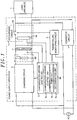
- a power supply apparatus includes a converter circuit 1 (AC/DC conversion unit) for performing AC/DC conversion to convert the power of an alternating current (AC) power source AC, implemented as a commercial power source, into DC power and supplying the DC power to a load appliance L; a secondary battery 2 functioning as a backup power source when a power failure occurs in the AC power source AC; a charging circuit 3 (charging unit) for performing AC/DC conversion to convert the power of the AC power source AC into DC power and charging the secondary battery 2 with constant current; a discharging circuit 4 (discharging unit) for discharging the secondary battery 2; a charging/discharging controller 5 for controlling the respective operations of the charging circuit 3 and the discharging circuit 4; a power failure monitoring circuit 6 (power failure monitoring unit) for detecting a power failure in the AC power source AC; and a thermistor 7 for detecting the environmental temperature of the secondary battery 2.
- AC alternating current
- the load appliance L is driven by the DC power output from the converter circuit 1.
- the charging/discharging control unit 5a charges the secondary battery 2 with constant current by operating the charging circuit 3 as needed in order to maintain the voltage of the secondary battery 2 at a predetermined voltage.
- the power failure monitoring circuit 6 controls the output switch 4a to be turned off (opened), and the charging/discharging control unit 5a operates the compulsory discharging circuit 4b.
- the compulsory discharging circuit 4b has the function of compulsorily keeping the secondary battery 2 in a discharge state of a predetermined capacity by connecting a dummy load such as a resistor (not shown) between both ends of the secondary battery 2.
- the secondary battery 2 is compulsorily kept in a discharge state, thus preventing the instantaneous interruption of the load appliance L from occurring when the output switch 4a is ON-controlled upon detecting a power failure, which will be described later.
- the power failure monitoring circuit 6 controls the output switch 4a to be turned on, and also outputs a power failure occurrence signal to the charging/discharging control unit 5a.
- the charging/discharging control unit 5a that has received the power failure occurrence signal stops the compulsory discharging circuit 4b and allows DC power to be supplied from the secondary battery 2 to the load appliance L via the output switch 4a.
- a residual capacity enabling the supply of power is required at least during a period in which backup is guaranteed.
- the power consumption of the load appliance L in the present embodiment is 50 W and a backup guarantee period is 1 hour (1h)
- SOC State Of Charge
- the charging/discharging control unit 5a detects the SOC of the secondary battery 2 by monitoring the battery voltage. Further, the charging/discharging control unit 5a according to the present embodiment starts to charge the secondary battery 2 by using the charging circuit 3 if the SOC of the secondary battery 2 decreases to 50% during the normal period, and stops the charging circuit 3 if the SOC reaches a predetermined value (for example, 60%). Alternatively, discharging power by the compulsory discharging circuit 4b may be compensated by charging the secondary battery and the SOC to maintain SOC 50%.
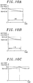
- the secondary battery 2 implemented as a lithium-ion battery is kept in SOC 100% (characteristic Y1) and in SOC 60% (characteristic Y2)
- the former case corresponding to the SOC 100% causes the degradation of capacity to proceed faster. That is, in the degradation of the capacity of the secondary battery 2, as the residual capacity is higher, the speed of degradation becomes higher. Therefore, in order to lengthen the lifespan of the secondary battery 2, the secondary battery is suppressed to a low SOC of about 50 to 60% to guarantee the lifespan without being charged up to SOC 100%.
- the charging/discharging controller 5 determines the degraded state of the secondary battery 2.
- the flowchart of the operations of the power supply apparatus performed during the normal time is shown in Fig. 4 .
- the charging/discharging control unit 5a determines whether the battery voltage is equal to or less than a battery voltage corresponding to a backup guarantee SOC (for example, 50% in an initial state) set for the guarantee of backup (hereinafter, referred to as a "backup guarantee voltage Vb") (step S1). If the battery voltage is equal to or less than the backup guarantee voltage Vb, the charging of the secondary battery 2 starts by using the charging circuit 3 (step S2). It is determined whether the battery voltage has reached a battery voltage corresponding to a charging termination SOC (for example, 60%) preset for the guarantee of lifespan (hereinafter, referred to as a “charging termination voltage Vs”) (step S3). If the battery voltage is less than the charging termination voltage Vs, the charging operation continues to be performed.
- a battery voltage corresponding to a backup guarantee SOC for example, 50% in an initial state
- Vb backup guarantee voltage
- step S4 if the battery voltage is greater than the backup guarantee voltage Vb at step S1, or if the battery voltage has reached the charging termination voltage Vs at step S3, it is determined whether the time to determine the lifespan of the secondary battery 2 has been reached (step S4).
- the lifespan determination time for the secondary battery 2 is set at predetermined regular periods (for example, once a month), so that the process returns to step S1 to repeat the above process if the lifespan determination time has not been reached.
- the charging/discharging control unit 5a makes the battery voltage identical to an initial backup guarantee voltage Vb0 by using the charging circuit 3 or the discharging circuit 4, and thereafter starts to charge the secondary battery 2 by using the charging circuit 3 (step S5).
- the charging/discharging control unit 5a determines whether the battery voltage has reached a battery voltage corresponding to a second SOC (for example, 100%) preset for the determination of lifespan (hereinafter, referred to as a "lifespan determination voltage Vh”) (step S6). If the battery voltage is less than the lifespan determination voltage Vh, the charging operation continues to be performed.
- the timer unit 5b measures the time required to perform charging from the initial backup guarantee voltage Vb0 to the lifespan determination voltage Vh (charging time), and the determination unit 5c determines the degraded state of the secondary battery 2 based on the charging time if it is determined at step S6 that the battery voltage has reached the lifespan determination voltage Vh (step S7).
- the initial backup guarantee voltage Vb0 is a backup guarantee voltage set for the initial secondary battery 2 (the battery voltage corresponding to a first SOC (for example, SOC 50%) identical to an initial backup guarantee SOC).
- a determination process for determining the degraded state of the secondary battery 2 in consideration of charging time will be described in detail.
- a battery voltage of 3.9V corresponding to first SOC 50% is an initial backup guarantee voltage Vb0 and a battery voltage of 4.2V corresponding to second SOC 100% is a lifespan determination voltage Vh
- the charging time (the measured charging time) from the initial backup guarantee voltage Vb0 to the lifespan determination voltage Vh is assumed to be t1.
- the determination unit 5c stores the initial charging time t0 (the initial time required) it takes the initial secondary battery 2 to be charged in a range of SOC 50% to 100%, and determines the degraded state of the secondary battery 2 on the basis of the ratio of the measured charging time t1 to the initial charging time t0 (t1/t0).
- the secondary battery 2 is determined to be gradually degraded.
- the process can be simplified compared to the determination process based on the capacity of the secondary battery 2, which will be described below.
- the determination unit 5c may determine the degraded state of the secondary battery 2 on the basis of the capacity of the secondary battery 2 that is derived in consideration of the charging time.
- a battery voltage of 3.9V corresponding to the first SOC 50% is an initial backup guarantee voltage Vb0
- a battery voltage of 4.2V corresponding to the second SOC 100% is a lifespan determination voltage Vh
- charging power for constant current charging performed by the charging circuit 3 is P1 W
- the charging time (the measured charging time) from the initial backup guarantee voltage Vb0 to the lifespan determination voltage Vh is t1.
- the secondary battery 2 is determined to be degraded. In this way, by comparing the capacity C1 of the secondary battery 2 that is derived based on the charging time with the initial capacity C0, it is possible to determine the degraded state of the secondary battery 2.
- the initial charging time t0 may be measured by using the initial secondary battery 2 (see Fig. 5A ), and results obtained by calculating the following Equation (4) may be stored.
- C 0 Wh t 0 h ⁇ P 1 W ⁇ charge SOC % ⁇ 100
- the lifespan determination voltage Vh may be set to a battery voltage corresponding to, for example, SOC 60%, rather than SOC 100%. However, since the charging time is decreased, charging to a higher SOC level is more profitable from the standpoint of the accuracy of the determination.
- the determination unit 5c determines whether the degraded state of the secondary battery 2 is in progress, based on the degraded state of the secondary battery 2 obtained in the above Equation (1) or (3) (step S8).
- the degraded state has decreased to 0.9
- the measured capacity C1 is decreased to 90% of the initial capacity C0, so that capacity in SOC 100% is 90 Wh. Therefore, in order to secure a capacity of 50 Wh required for backup, a backup guarantee SOC of 56% is required.
- the charging/discharging control unit 5a sets the backup guarantee voltage Vb to 4.0V corresponding to the backup guarantee SOC 56%, and then corrects the backup guarantee voltage Vb depending on the degraded state of the secondary battery 2 (step S9). Further, with the correction of the backup guarantee voltage Vb, the charging termination voltage Vs is also corrected. Thereafter, the charging/discharging control unit 5a controls charging/discharging during the normal period at steps S1 to S3 by using the corrected backup guarantee voltage Vb and the corrected charging termination voltage Vs (see Fig. 5C ), thus securing a capacity of 50 Wh required for backup regardless of the degraded state of the secondary battery 2. That is, the charging/discharging control unit 5a sets the SOC of the secondary battery 2 for the normal period, depending on the degraded state of the secondary battery 2 determined by the determination unit 5c.
- the correction of the backup guarantee voltage Vb at steps S5 to S9 is periodically performed, and thus the correction of the charging termination voltage Vs is performed accordingly.
- a notification of this decrease is provided to the user by using a notification unit (not shown) such as an indication lamp or a buzzer, and the user is prompted to replace the secondary battery 2.
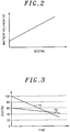
- a relationship between the temperature and the battery capacity of the secondary battery 2 shows that as the battery temperature becomes lower, the battery capacity becomes lower, as shown in Fig. 6 . Therefore, in the case where temperature correction is not performed, there is a fear that the capacity (Wh) required for backup cannot be secured if the temperature of the secondary battery 2 decreases. Therefore, the charging/discharging control unit 5a stores, as the temperature characteristics of the secondary battery 2, a relationship between the temperature of the secondary battery and the backup guarantee SOC needed to secure the capacity (Wh) required for backup, as shown in Fig. 7 . Further, the temperature characteristics of the secondary battery 2 shown in Fig.
- a single temperature characteristic pattern for each degraded state of the secondary battery 2 is stored and a component for varying the temperature characteristic pattern depending on the degraded state of the secondary battery 2 is provided.
- the environmental temperature of the secondary battery 2 having a correlation with the temperature of the secondary battery 2 is measured by the thermistor 7.
- the charging/discharging control unit 5a compares the environmental temperature measured by the thermistor 7 with the temperature characteristics shown in Fig. 7 , calculates the backup guarantee SOC required for the current environmental temperature, and corrects both the backup guarantee voltage Vb and the charging termination voltage Vs on the basis of the calculated backup guarantee SOC, thus securing the capacity (Wh) required for backup regardless of the temperature of the secondary battery 2. That is, the charging/discharging control unit 5a sets the backup guarantee SOC of the secondary battery 2 for the normal period depending on the temperature of the secondary battery 2. Further, since the environmental temperature continuously varies, the temperature correction of the backup guarantee voltage Vb by the charging/discharging control unit 5a can be simplified if SOC levels required for respective predetermined temperature ranges have been defined, as shown in Fig. 8 .
- the configuration of a power supply apparatus in the present embodiment is identical to that of the first embodiment, so that the same reference numerals are assigned to identical components and redundant description thereof will be omitted.
- the charging/discharging controller 5 determines the degraded state of the secondary battery 2 in consideration of the discharging time.
- the flowchart of the operations of the power supply apparatus performed during the normal period is shown in Fig. 9 .
- the charging/discharging control unit 5a controls charging/discharging during the normal period at steps S1 to S3 by using the backup guarantee voltage Vb and the charging termination voltage Vs, and then returns to step S1 to repeat the process if the lifespan determination time, for example, once a month, has not been reached at step S4.
- the charging/discharging control unit 5a makes the battery voltage identical to the lifespan determination voltage Vh by using the charging circuit 3, and starts to discharge the secondary battery 2 by using the compulsory discharging circuit 4b of the discharging circuit 4 (step S15).
- the charging/discharging control unit 5a determines whether the battery voltage has decreased to the initial backup guarantee voltage Vb0 (step S16), and continues to perform a discharge operation if the battery voltage is greater than the initial backup guarantee voltage Vb0.
- the timer unit 5b measures the time required to perform discharging from the lifespan determination voltage Vh to the initial backup guarantee voltage Vb0 (discharging time), so that the determination unit 5c determines the degraded state of the secondary battery 2 based on the discharging time if it is determined at step S16 that the battery voltage has decreased to the initial backup guarantee voltage Vb0 (step S17).
- a battery voltage of 3.9V corresponding to a first SOC 50% is the initial backup guarantee voltage Vb0 and a battery voltage of 4.2V corresponding to a second SOC 100% is the lifespan determination voltage Vh
- the charging time from the lifespan determination voltage Vh to the initial backup guarantee voltage Vb0 is assumed to be t11.
- the determination unit 5c stores initial discharging time t10 (the initial time required) it takes the initial secondary battery 2 to be discharged in a range of SOC 100% ⁇ 50%, and determines the degraded state of the secondary battery 2 on the basis of the ratio of the measured discharging time t11 to the initial discharging time t10 (t11/t10).
- the secondary battery 2 is determined to be degraded.
- the process can be simplified compared to the determination process based on the capacity of the secondary battery 2, which will be described below.
- the determination unit 5c may determine the degraded state of the secondary battery 2 on the basis of the capacity of the secondary battery 2 that is derived in consideration of the discharging time.
- a battery voltage of 3.9V corresponding to the first SOC 50% is the initial backup guarantee voltage Vb0
- a battery voltage of 4.2V corresponding to the second SOC 100% is the lifespan determination voltage Vh
- discharging power for compulsory discharging performed by the compulsory discharging circuit 4b is P11 W
- the discharging time (the measured charging time) from the lifespan determination voltage Vh to the initial backup guarantee voltage Vb0 is t11.
- the capacity C11 (Wh) of the current secondary battery 2 in SOC 100% (hereinafter, referred to as a "measured capacity C11") is given by the following Equation (6):
- C 11 Wh t 11 h ⁇ P 11 W ⁇ discharge SOC % ⁇ 100
- the secondary battery 2 is determined to be degraded.
- the initial discharging time t10 may be measured by using the initial secondary battery 2 (see Fig. 10A ), and results obtained by calculating the following Equation (8) may be stored.
- C 10 Wh t 10 h ⁇ P 11 W ⁇ discharge SOC % ⁇ 100
- the lifespan determination voltage Vh may be set to a battery voltage corresponding to, for example, SOC 60%, rather than SOC 100%. However, since the discharging time is decreased, discharging from a higher SOC level is more profitable from the standpoint of the accuracy of the determination.
- the determination unit 5c determines whether the degraded state of the secondary battery 2 is in progress, based on the degraded state of the secondary battery 2 obtained in the above Equation (5) or (7) (step S18).
- the degraded state has decreased to 0.9
- the measured capacity C1 is decreased to 90% of the initial capacity C0, so that the capacity in SOC 100% is 90 Wh. Therefore, in order to secure a capacity of 50 Wh required for backup, a backup guarantee SOC of 56% is required.
- the charging/discharging control unit 5a sets 4.0V corresponding to the backup guarantee SOC 56% as the backup guarantee voltage Vb, and then corrects the backup guarantee voltage Vb depending on the degraded state of the secondary battery 2 (step S19). Further, with the correction of the backup guarantee voltage Vb, the charging termination voltage Vs is also corrected. Thereafter, the charging/discharging control unit 5a controls charging/discharging during the normal period at steps S1 to S3 by using the corrected backup guarantee voltage Vb and the corrected charging termination voltage Vs (see Fig. 10C ), thus securing a capacity of 50 Wh required for backup regardless of the degraded state of the secondary battery 2. That is, the charging/discharging control unit 5a sets the SOC of the secondary battery 2 for the normal period, depending on the degraded state of the secondary battery 2 determined by the determination unit 5c.
- the correction of the backup guarantee voltage Vb at steps S15 to S19 is periodically performed, and thus the correction of the charging termination voltage Vs is performed accordingly.
- a notification of this decrease is provided to the user by using a notification unit (not shown) such as an indication lamp or a buzzer, and the user is prompted to replace the secondary battery 2.
- the charging/discharging control unit 5a performs a temperature correction on the backup guarantee voltage Vb and the charging termination voltage Vs on the basis of the environmental temperature measured by the thermistor 7.
- the configuration is simplified by using the compulsory discharging circuit 4b of the discharging circuit 4 for discharging at step S15, a discharging unit having a configuration different from that of the discharging circuit 4 may also be provided, and the power consumption of the load appliance L may be used for discharging.
Landscapes
- Physics & Mathematics (AREA)
- General Physics & Mathematics (AREA)
- Charge And Discharge Circuits For Batteries Or The Like (AREA)
- Secondary Cells (AREA)
- Tests Of Electric Status Of Batteries (AREA)
- Stand-By Power Supply Arrangements (AREA)
Claims (5)
- Appareil d'alimentation électrique comprenant :une batterie secondaire (2) ;une unité de temporisation (5b) pour mesurer un temps nécessaire pour charger la batterie secondaire (2) d'un premier SOC à un second SOC avec un courant constant, ou un temps nécessaire pour décharger la batterie secondaire (2) du second SOC au premier SOC avec une certaine énergie de décharge ; etune unité de détermination (5c) pour déterminer un état dégradé de la batterie secondaire (2) sur la base de résultats de la mesure par l'unité de temporisation (5b), caractérisé en ce que l'appareil d'alimentation électrique comprend en outre :une unité de charge (3) pour charger la batterie secondaire (2) ;une unité de décharge (4) pour décharger la batterie secondaire (2) ; etune unité de commande de charge/décharge (5a) pour commander la charge de la batterie secondaire (2) en utilisant l'unité de charge (3) et la décharge de la batterie secondaire (2) en utilisant l'unité de décharge (4),dans lequel l'unité de commande de charge/décharge (5a) commande l'unité de charge (3) de telle sorte que, à un moment prédéterminé, la batterie secondaire (2) est chargée du premier SOC au second SOC, ou commande l'unité de décharge (4) de telle sorte que, au moment prédéterminé, la batterie secondaire (2) est déchargée du second SOC au premier SOC,dans lequel la batterie secondaire (2) est chargée à une capacité prédéterminée ou plus et est ensuite utilisée comme source d'alimentation de secours pour apporter de l'énergie à un appareil de charge (L) en cas d'urgence, etdans lequel l'unité de commande de charge/décharge (5a) charge la batterie secondaire (2) à un SOC de garantie de secours ou plus, et fait varier le SOC de garantie de secours de telle sorte que la capacité de la batterie secondaire (2) devient la capacité prédéterminée ou plus en fonction de l'état dégradé de la batterie secondaire (2) déterminé par l'unité de détermination (5c).
- Appareil d'alimentation électrique selon la revendication 1, dans lequel l'unité de détermination (5c) stocke, comme temps initial nécessaire, le temps nécessaire pour charger la batterie secondaire initiale (2) du premier SOC au second SOC, ou le temps nécessaire pour décharger la batterie secondaire initiale (2) du second SOC au premier SOC, puis détermine l'état dégradé de la batterie secondaire (2) en comparant les résultats de la mesure par l'unité de temporisation (5b) au temps initial nécessaire.
- Appareil d'alimentation électrique selon la revendication 1, dans lequel l'unité de détermination (5c) stocke une capacité de la batterie secondaire (2), obtenue lorsque la batterie secondaire initiale (2) est dans le second SOC, en tant que capacité initiale, dérive la capacité de la batterie secondaire (2) dans le second SOC sur la base des résultats de la mesure par l'unité de temporisation (5b), et détermine l'état dégradé de la batterie secondaire (2) en comparant la capacité dérivée de la batterie secondaire (2) à la capacité initiale.
- Appareil d'alimentation électrique selon l'une quelconque des revendications 1 à 3, dans lequel l'unité de commande de charge/décharge (5a) commande la charge/décharge de telle sorte qu'une limite supérieure du SOC de la batterie secondaire (2) est inférieure à 100 %, et charge la batterie secondaire (2) du premier SOC de moins de 100 % au second SOC de 100 % ou décharge la batterie secondaire (2) du second SOC de 100 % au premier SOC de moins de 100 %, au moment prédéterminé.
- Appareil d'alimentation électrique selon la revendication 1, dans lequel l'unité de commande de charge/décharge (5a) fait varier le SOC de garantie de secours de telle sorte que la capacité de la batterie secondaire (2) devient la capacité prédéterminée ou plus en fonction d'une température de la batterie secondaire.
Applications Claiming Priority (2)
| Application Number | Priority Date | Filing Date | Title |
|---|---|---|---|
| JP2009244963A JP5789736B2 (ja) | 2009-10-23 | 2009-10-23 | 電力供給装置 |
| PCT/IB2010/002681 WO2011048471A1 (fr) | 2009-10-23 | 2010-10-20 | Dispositif de source d'alimentation électrique |
Publications (3)
| Publication Number | Publication Date |
|---|---|
| EP2492702A1 EP2492702A1 (fr) | 2012-08-29 |
| EP2492702A4 EP2492702A4 (fr) | 2017-05-03 |
| EP2492702B1 true EP2492702B1 (fr) | 2020-07-15 |
Family
ID=43899869
Family Applications (1)
| Application Number | Title | Priority Date | Filing Date |
|---|---|---|---|
| EP10824534.1A Active EP2492702B1 (fr) | 2009-10-23 | 2010-10-20 | Dispositif de source d'alimentation électrique |
Country Status (5)
| Country | Link |
|---|---|
| US (1) | US9086463B2 (fr) |
| EP (1) | EP2492702B1 (fr) |
| JP (1) | JP5789736B2 (fr) |
| CN (1) | CN102612656B (fr) |
| WO (1) | WO2011048471A1 (fr) |
Families Citing this family (29)
| Publication number | Priority date | Publication date | Assignee | Title |
|---|---|---|---|---|
| JP5143273B1 (ja) * | 2011-11-30 | 2013-02-13 | 株式会社東芝 | バッテリー管理装置及びバッテリー管理方法 |
| CN103135063A (zh) * | 2012-12-21 | 2013-06-05 | 郝勇 | 一种铅酸蓄电池的检测及监控方法 |
| DE112013006570T5 (de) * | 2013-02-01 | 2015-10-15 | Toyota Jidosha Kabushiki Kaisha | Batteriesystem |
| WO2015047415A1 (fr) * | 2013-09-30 | 2015-04-02 | Hewlett-Packard Development Company, Lp | Électricité de secours activée de façon sélective |
| JP2015155859A (ja) * | 2014-02-21 | 2015-08-27 | ソニー株式会社 | 電池残量推定装置、電池パック、蓄電装置、電動車両および電池残量推定方法 |
| JP5742999B2 (ja) * | 2014-04-08 | 2015-07-01 | 三菱自動車工業株式会社 | 充電時間推定装置および充電時間推定方法 |
| WO2015200912A1 (fr) * | 2014-06-27 | 2015-12-30 | Icc-Nexergy, Inc. | Indication de puissance disponible requise pour unité de batterie de secours |
| EP3010112A1 (fr) * | 2014-10-14 | 2016-04-20 | Pace Plc | Procédé et système pour chargement d'une batterie |
| JP6054934B2 (ja) * | 2014-11-17 | 2016-12-27 | レノボ・シンガポール・プライベート・リミテッド | 二次電池の寿命期間を延長するバックアップ・システム、管理方法および情報処理装置 |
| US10008879B2 (en) * | 2014-12-11 | 2018-06-26 | Fisher Controls International Llc | Self-discharging reserve power units and related methods |
| US20160202749A1 (en) * | 2015-01-13 | 2016-07-14 | Netlist, Inc. | System and method for determining charge of a secondary power supply for a memory system |
| US10403936B2 (en) * | 2015-01-15 | 2019-09-03 | Nec Corporation | Storage cell control system, storage cell control method, and recording medium |
| JP5862815B1 (ja) * | 2015-03-06 | 2016-02-16 | 日本電気株式会社 | バッテリ寿命検出装置、蓄電装置、バッテリ寿命検出方法及びプログラム |
| US10386421B2 (en) * | 2015-09-14 | 2019-08-20 | Facebook, Inc. | Energy based battery backup unit testing |
| JP2017181484A (ja) * | 2016-03-28 | 2017-10-05 | Ntn株式会社 | 二次電池の劣化判定装置 |
| WO2017170205A1 (fr) * | 2016-03-28 | 2017-10-05 | Ntn株式会社 | Dispositif d'évaluation de dégradation de batterie secondaire |
| JP2018002435A (ja) * | 2016-07-06 | 2018-01-11 | 株式会社日立製作所 | エレベータ装置 |
| CN106646262A (zh) * | 2017-01-03 | 2017-05-10 | 重庆长安汽车股份有限公司 | 一种动力电池容量估算方法、系统及电动汽车 |
| JP6981015B2 (ja) * | 2017-02-27 | 2021-12-15 | 日本電気株式会社 | 電力供給システム、制御装置、制御方法及びプログラム |
| JP7054868B2 (ja) * | 2017-12-26 | 2022-04-15 | パナソニックIpマネジメント株式会社 | 電池管理装置、電池システム、及び車両用電源システム |
| US10868431B2 (en) | 2018-01-16 | 2020-12-15 | Cisco Technology, Inc. | Battery charging cut-off circuit |
| KR102442632B1 (ko) | 2018-02-09 | 2022-09-08 | 주식회사 엘지에너지솔루션 | 이차 전지 상태 추정 장치 및 방법 |
| CN108549031A (zh) * | 2018-03-26 | 2018-09-18 | 奇瑞汽车股份有限公司 | 一种动力电池循环耐久试验台架 |
| JP7378921B2 (ja) * | 2018-10-19 | 2023-11-14 | 三菱重工業株式会社 | 二次電池管理システム、及びその二次電池管理方法並びに二次電池管理プログラム、二次電池システム |
| JP7149836B2 (ja) * | 2018-12-21 | 2022-10-07 | 株式会社日立製作所 | 電源システム、診断装置及び無停電電源装置 |
| DE102020201836A1 (de) * | 2020-02-14 | 2021-08-19 | Robert Bosch Gesellschaft mit beschränkter Haftung | Verfahren zur Bestimmung des Alterungszustandes mindestens einer elektrischen Energiespeichereinheit |
| US20220200295A1 (en) * | 2020-12-23 | 2022-06-23 | Medtronic, Inc. | Systems and method for charging batteries |
| CN116250110A (zh) * | 2021-02-09 | 2023-06-09 | 宁德时代新能源科技股份有限公司 | 电池充电方法、控制器、电池管理系统、电池和用电装置 |
| EP4207537A1 (fr) * | 2021-12-29 | 2023-07-05 | Polarium Energy Solutions AB | Procédé et module de batterie avec détermination d'état |
Family Cites Families (21)
| Publication number | Priority date | Publication date | Assignee | Title |
|---|---|---|---|---|
| US5018148A (en) * | 1989-03-01 | 1991-05-21 | Ncr Corporation | Method and apparatus for power failure protection |
| JP2727149B2 (ja) * | 1992-09-14 | 1998-03-11 | エムアンドシー 株式会社 | バッテリー検査方法 |
| US5606242A (en) * | 1994-10-04 | 1997-02-25 | Duracell, Inc. | Smart battery algorithm for reporting battery parameters to an external device |
| JP3322116B2 (ja) | 1996-02-28 | 2002-09-09 | 新神戸電機株式会社 | 交流無停電電源装置の蓄電池劣化状態試験装置 |
| DE69826929T2 (de) * | 1997-06-24 | 2005-03-10 | Matsushita Electric Industrial Co., Ltd., Kadoma | Verfahren zur Erfassung des Betriebszustandes wiederaufladbarer Batterien mit nicht wasserhaltigem Elektrolyt |
| JP3659772B2 (ja) * | 1997-08-07 | 2005-06-15 | 三菱自動車工業株式会社 | バッテリの劣化判定装置 |
| EP0921620B1 (fr) * | 1997-12-03 | 2005-07-20 | Matsushita Electric Industrial Co., Ltd. | Méthode pour charger, en fonction de la température, une source de puissance de veille qui est soumise à une autodécharge. |
| TW200417706A (en) * | 2003-03-13 | 2004-09-16 | Wetek Corp | The method and apparatus for auto charging-discharging and monitoring of the urgent lighting |
| JP4649101B2 (ja) * | 2003-09-10 | 2011-03-09 | 株式会社日本自動車部品総合研究所 | 二次電池の状態検知装置および状態検知方法 |
| JP4134877B2 (ja) * | 2003-10-20 | 2008-08-20 | トヨタ自動車株式会社 | 蓄電機構の制御装置 |
| EP1632781A1 (fr) * | 2004-09-02 | 2006-03-08 | Delphi Technologies, Inc. | Procédé et dispositif de détection de la capacité d'une batterie |
| JP2006177764A (ja) * | 2004-12-22 | 2006-07-06 | Sanyo Electric Co Ltd | 電池の学習容量補正方法 |
| CN100535680C (zh) | 2005-08-19 | 2009-09-02 | 株式会社Ntt设施 | 劣化判断装置、劣化判断方法、计算机程序 |
| JP5460943B2 (ja) | 2005-08-19 | 2014-04-02 | 株式会社Nttファシリティーズ | 劣化判定装置、劣化判定方法、コンピュータプログラム |
| US20070080692A1 (en) * | 2005-09-12 | 2007-04-12 | Evans Glen F | Method and apparatus for performing automated power plant battery backup capacity measurement |
| JP2007166789A (ja) * | 2005-12-14 | 2007-06-28 | Toyota Motor Corp | 二次電池の満充電容量の推定方法と判別装置 |
| CN100541396C (zh) | 2006-01-16 | 2009-09-16 | 宏碁股份有限公司 | 延长便携式计算机的电池寿命的方法 |
| US7800344B2 (en) * | 2007-02-20 | 2010-09-21 | Delphi Technologies, Inc. | Method of determining the energy capacity of a battery |
| US8558508B2 (en) * | 2007-06-08 | 2013-10-15 | C & C Power, Inc. | Battery system and management method |
| JP2009012345A (ja) | 2007-07-05 | 2009-01-22 | Seiko Epson Corp | 液体吐出装置 |
| JP4494453B2 (ja) * | 2007-11-13 | 2010-06-30 | トヨタ自動車株式会社 | 二次電池の制御装置および制御方法 |
-
2009
- 2009-10-23 JP JP2009244963A patent/JP5789736B2/ja active Active
-
2010
- 2010-10-20 CN CN201080047099.0A patent/CN102612656B/zh not_active Expired - Fee Related
- 2010-10-20 EP EP10824534.1A patent/EP2492702B1/fr active Active
- 2010-10-20 WO PCT/IB2010/002681 patent/WO2011048471A1/fr active Application Filing
- 2010-10-20 US US13/503,434 patent/US9086463B2/en not_active Expired - Fee Related
Non-Patent Citations (1)
| Title |
|---|
| None * |
Also Published As
| Publication number | Publication date |
|---|---|
| EP2492702A1 (fr) | 2012-08-29 |
| EP2492702A4 (fr) | 2017-05-03 |
| US20120248876A1 (en) | 2012-10-04 |
| JP2011089938A (ja) | 2011-05-06 |
| WO2011048471A1 (fr) | 2011-04-28 |
| JP5789736B2 (ja) | 2015-10-07 |
| CN102612656A (zh) | 2012-07-25 |
| US9086463B2 (en) | 2015-07-21 |
| CN102612656B (zh) | 2015-07-29 |
Similar Documents
| Publication | Publication Date | Title |
|---|---|---|
| EP2492702B1 (fr) | Dispositif de source d'alimentation électrique | |
| US8203314B2 (en) | Surface temperature dependent battery cell charging system | |
| JP5036556B2 (ja) | リチウムイオンまたはリチウムポリマーのバッテリをバランス充電するための方法 | |
| US6124698A (en) | Battery charger | |
| CN108885242B (zh) | 二次电池劣化估计装置和二次电池劣化估计方法 | |
| JP4817647B2 (ja) | 二次電池の寿命判定方法。 | |
| US8203305B1 (en) | Enhanced voltage-based fuel gauges and methods | |
| US20110112782A1 (en) | Battery status detection device | |
| JP6824614B2 (ja) | 劣化判定装置及び劣化判定方法 | |
| US20120290236A1 (en) | Battery condition detecting apparatus | |
| US20090128159A1 (en) | Battery pack anomaly detecting method and battery pack | |
| KR102441800B1 (ko) | 배터리 수명 예측 방법 및 장치 | |
| JP2011053088A (ja) | 二次電池の残容量演算方法および二次電池装置 | |
| EP3444625A1 (fr) | Dispositif de stockage d'électricité, système de stockage d'électricité et système d'alimentation électrique | |
| JP2011043460A (ja) | 二次電池の特性検出方法および二次電池装置 | |
| JP2012253975A (ja) | アルカリ蓄電池の充放電制御方法および充放電システム | |
| JP2013178166A (ja) | 二次電池の残容量補正方法、二次電池の残容量算出方法及びパック電池 | |
| JP5473277B2 (ja) | 充電装置 | |
| CN110780217B (zh) | 半导体装置、以及蓄电池的余量的检测方法 | |
| JP3732465B2 (ja) | 鉄道車両用蓄電池状態監視装置 | |
| JP4329543B2 (ja) | 電池の残量計測装置 | |
| JP2011038878A (ja) | 二次電池の劣化度判定方法および二次電池装置 | |
| JP6631377B2 (ja) | 充電量算出装置、コンピュータプログラム及び充電量算出方法 | |
| JP2008029087A (ja) | 電子機器システム | |
| JP4660367B2 (ja) | 二次電池の残存容量検出方法 |
Legal Events
| Date | Code | Title | Description |
|---|---|---|---|
| PUAI | Public reference made under article 153(3) epc to a published international application that has entered the european phase |
Free format text: ORIGINAL CODE: 0009012 |
|
| 17P | Request for examination filed |
Effective date: 20120420 |
|
| AK | Designated contracting states |
Kind code of ref document: A1 Designated state(s): AL AT BE BG CH CY CZ DE DK EE ES FI FR GB GR HR HU IE IS IT LI LT LU LV MC MK MT NL NO PL PT RO RS SE SI SK SM TR |
|
| DAX | Request for extension of the european patent (deleted) | ||
| RAP1 | Party data changed (applicant data changed or rights of an application transferred) |
Owner name: PANASONIC INTELLECTUAL PROPERTY MANAGEMENT CO., LT |
|
| RA4 | Supplementary search report drawn up and despatched (corrected) |
Effective date: 20170330 |
|
| RIC1 | Information provided on ipc code assigned before grant |
Ipc: G01R 31/36 20060101AFI20170325BHEP |
|
| GRAP | Despatch of communication of intention to grant a patent |
Free format text: ORIGINAL CODE: EPIDOSNIGR1 |
|
| STAA | Information on the status of an ep patent application or granted ep patent |
Free format text: STATUS: GRANT OF PATENT IS INTENDED |
|
| INTG | Intention to grant announced |
Effective date: 20200129 |
|
| GRAS | Grant fee paid |
Free format text: ORIGINAL CODE: EPIDOSNIGR3 |
|
| GRAA | (expected) grant |
Free format text: ORIGINAL CODE: 0009210 |
|
| STAA | Information on the status of an ep patent application or granted ep patent |
Free format text: STATUS: THE PATENT HAS BEEN GRANTED |
|
| AK | Designated contracting states |
Kind code of ref document: B1 Designated state(s): AL AT BE BG CH CY CZ DE DK EE ES FI FR GB GR HR HU IE IS IT LI LT LU LV MC MK MT NL NO PL PT RO RS SE SI SK SM TR |
|
| REG | Reference to a national code |
Ref country code: CH Ref legal event code: EP Ref country code: GB Ref legal event code: FG4D |
|
| REG | Reference to a national code |
Ref country code: IE Ref legal event code: FG4D |
|
| REG | Reference to a national code |
Ref country code: DE Ref legal event code: R096 Ref document number: 602010064940 Country of ref document: DE |
|
| REG | Reference to a national code |
Ref country code: AT Ref legal event code: REF Ref document number: 1291615 Country of ref document: AT Kind code of ref document: T Effective date: 20200815 |
|
| REG | Reference to a national code |
Ref country code: LT Ref legal event code: MG4D |
|
| REG | Reference to a national code |
Ref country code: AT Ref legal event code: MK05 Ref document number: 1291615 Country of ref document: AT Kind code of ref document: T Effective date: 20200715 |
|
| REG | Reference to a national code |
Ref country code: NL Ref legal event code: MP Effective date: 20200715 |
|
| PG25 | Lapsed in a contracting state [announced via postgrant information from national office to epo] |
Ref country code: FI Free format text: LAPSE BECAUSE OF FAILURE TO SUBMIT A TRANSLATION OF THE DESCRIPTION OR TO PAY THE FEE WITHIN THE PRESCRIBED TIME-LIMIT Effective date: 20200715 Ref country code: PT Free format text: LAPSE BECAUSE OF FAILURE TO SUBMIT A TRANSLATION OF THE DESCRIPTION OR TO PAY THE FEE WITHIN THE PRESCRIBED TIME-LIMIT Effective date: 20201116 Ref country code: AT Free format text: LAPSE BECAUSE OF FAILURE TO SUBMIT A TRANSLATION OF THE DESCRIPTION OR TO PAY THE FEE WITHIN THE PRESCRIBED TIME-LIMIT Effective date: 20200715 Ref country code: GR Free format text: LAPSE BECAUSE OF FAILURE TO SUBMIT A TRANSLATION OF THE DESCRIPTION OR TO PAY THE FEE WITHIN THE PRESCRIBED TIME-LIMIT Effective date: 20201016 Ref country code: SE Free format text: LAPSE BECAUSE OF FAILURE TO SUBMIT A TRANSLATION OF THE DESCRIPTION OR TO PAY THE FEE WITHIN THE PRESCRIBED TIME-LIMIT Effective date: 20200715 Ref country code: NO Free format text: LAPSE BECAUSE OF FAILURE TO SUBMIT A TRANSLATION OF THE DESCRIPTION OR TO PAY THE FEE WITHIN THE PRESCRIBED TIME-LIMIT Effective date: 20201015 Ref country code: BG Free format text: LAPSE BECAUSE OF FAILURE TO SUBMIT A TRANSLATION OF THE DESCRIPTION OR TO PAY THE FEE WITHIN THE PRESCRIBED TIME-LIMIT Effective date: 20201015 Ref country code: LT Free format text: LAPSE BECAUSE OF FAILURE TO SUBMIT A TRANSLATION OF THE DESCRIPTION OR TO PAY THE FEE WITHIN THE PRESCRIBED TIME-LIMIT Effective date: 20200715 Ref country code: ES Free format text: LAPSE BECAUSE OF FAILURE TO SUBMIT A TRANSLATION OF THE DESCRIPTION OR TO PAY THE FEE WITHIN THE PRESCRIBED TIME-LIMIT Effective date: 20200715 Ref country code: HR Free format text: LAPSE BECAUSE OF FAILURE TO SUBMIT A TRANSLATION OF THE DESCRIPTION OR TO PAY THE FEE WITHIN THE PRESCRIBED TIME-LIMIT Effective date: 20200715 |
|
| PG25 | Lapsed in a contracting state [announced via postgrant information from national office to epo] |
Ref country code: PL Free format text: LAPSE BECAUSE OF FAILURE TO SUBMIT A TRANSLATION OF THE DESCRIPTION OR TO PAY THE FEE WITHIN THE PRESCRIBED TIME-LIMIT Effective date: 20200715 Ref country code: RS Free format text: LAPSE BECAUSE OF FAILURE TO SUBMIT A TRANSLATION OF THE DESCRIPTION OR TO PAY THE FEE WITHIN THE PRESCRIBED TIME-LIMIT Effective date: 20200715 Ref country code: LV Free format text: LAPSE BECAUSE OF FAILURE TO SUBMIT A TRANSLATION OF THE DESCRIPTION OR TO PAY THE FEE WITHIN THE PRESCRIBED TIME-LIMIT Effective date: 20200715 Ref country code: IS Free format text: LAPSE BECAUSE OF FAILURE TO SUBMIT A TRANSLATION OF THE DESCRIPTION OR TO PAY THE FEE WITHIN THE PRESCRIBED TIME-LIMIT Effective date: 20201115 |
|
| PG25 | Lapsed in a contracting state [announced via postgrant information from national office to epo] |
Ref country code: NL Free format text: LAPSE BECAUSE OF FAILURE TO SUBMIT A TRANSLATION OF THE DESCRIPTION OR TO PAY THE FEE WITHIN THE PRESCRIBED TIME-LIMIT Effective date: 20200715 |
|
| REG | Reference to a national code |
Ref country code: DE Ref legal event code: R097 Ref document number: 602010064940 Country of ref document: DE |
|
| PG25 | Lapsed in a contracting state [announced via postgrant information from national office to epo] |
Ref country code: EE Free format text: LAPSE BECAUSE OF FAILURE TO SUBMIT A TRANSLATION OF THE DESCRIPTION OR TO PAY THE FEE WITHIN THE PRESCRIBED TIME-LIMIT Effective date: 20200715 Ref country code: DK Free format text: LAPSE BECAUSE OF FAILURE TO SUBMIT A TRANSLATION OF THE DESCRIPTION OR TO PAY THE FEE WITHIN THE PRESCRIBED TIME-LIMIT Effective date: 20200715 Ref country code: CZ Free format text: LAPSE BECAUSE OF FAILURE TO SUBMIT A TRANSLATION OF THE DESCRIPTION OR TO PAY THE FEE WITHIN THE PRESCRIBED TIME-LIMIT Effective date: 20200715 Ref country code: IT Free format text: LAPSE BECAUSE OF FAILURE TO SUBMIT A TRANSLATION OF THE DESCRIPTION OR TO PAY THE FEE WITHIN THE PRESCRIBED TIME-LIMIT Effective date: 20200715 Ref country code: RO Free format text: LAPSE BECAUSE OF FAILURE TO SUBMIT A TRANSLATION OF THE DESCRIPTION OR TO PAY THE FEE WITHIN THE PRESCRIBED TIME-LIMIT Effective date: 20200715 Ref country code: SM Free format text: LAPSE BECAUSE OF FAILURE TO SUBMIT A TRANSLATION OF THE DESCRIPTION OR TO PAY THE FEE WITHIN THE PRESCRIBED TIME-LIMIT Effective date: 20200715 |
|
| PLBE | No opposition filed within time limit |
Free format text: ORIGINAL CODE: 0009261 |
|
| STAA | Information on the status of an ep patent application or granted ep patent |
Free format text: STATUS: NO OPPOSITION FILED WITHIN TIME LIMIT |
|
| PG25 | Lapsed in a contracting state [announced via postgrant information from national office to epo] |
Ref country code: AL Free format text: LAPSE BECAUSE OF FAILURE TO SUBMIT A TRANSLATION OF THE DESCRIPTION OR TO PAY THE FEE WITHIN THE PRESCRIBED TIME-LIMIT Effective date: 20200715 |
|
| REG | Reference to a national code |
Ref country code: CH Ref legal event code: PL |
|
| 26N | No opposition filed |
Effective date: 20210416 |
|
| GBPC | Gb: european patent ceased through non-payment of renewal fee |
Effective date: 20201020 |
|
| PG25 | Lapsed in a contracting state [announced via postgrant information from national office to epo] |
Ref country code: LU Free format text: LAPSE BECAUSE OF NON-PAYMENT OF DUE FEES Effective date: 20201020 Ref country code: MC Free format text: LAPSE BECAUSE OF FAILURE TO SUBMIT A TRANSLATION OF THE DESCRIPTION OR TO PAY THE FEE WITHIN THE PRESCRIBED TIME-LIMIT Effective date: 20200715 Ref country code: SK Free format text: LAPSE BECAUSE OF FAILURE TO SUBMIT A TRANSLATION OF THE DESCRIPTION OR TO PAY THE FEE WITHIN THE PRESCRIBED TIME-LIMIT Effective date: 20200715 |
|
| REG | Reference to a national code |
Ref country code: BE Ref legal event code: MM Effective date: 20201031 |
|
| PG25 | Lapsed in a contracting state [announced via postgrant information from national office to epo] |
Ref country code: FR Free format text: LAPSE BECAUSE OF NON-PAYMENT OF DUE FEES Effective date: 20201031 |
|
| PG25 | Lapsed in a contracting state [announced via postgrant information from national office to epo] |
Ref country code: BE Free format text: LAPSE BECAUSE OF NON-PAYMENT OF DUE FEES Effective date: 20201031 Ref country code: CH Free format text: LAPSE BECAUSE OF NON-PAYMENT OF DUE FEES Effective date: 20201031 Ref country code: SI Free format text: LAPSE BECAUSE OF FAILURE TO SUBMIT A TRANSLATION OF THE DESCRIPTION OR TO PAY THE FEE WITHIN THE PRESCRIBED TIME-LIMIT Effective date: 20200715 Ref country code: GB Free format text: LAPSE BECAUSE OF NON-PAYMENT OF DUE FEES Effective date: 20201020 Ref country code: LI Free format text: LAPSE BECAUSE OF NON-PAYMENT OF DUE FEES Effective date: 20201031 |
|
| PG25 | Lapsed in a contracting state [announced via postgrant information from national office to epo] |
Ref country code: IE Free format text: LAPSE BECAUSE OF NON-PAYMENT OF DUE FEES Effective date: 20201020 |
|
| PG25 | Lapsed in a contracting state [announced via postgrant information from national office to epo] |
Ref country code: TR Free format text: LAPSE BECAUSE OF FAILURE TO SUBMIT A TRANSLATION OF THE DESCRIPTION OR TO PAY THE FEE WITHIN THE PRESCRIBED TIME-LIMIT Effective date: 20200715 Ref country code: MT Free format text: LAPSE BECAUSE OF FAILURE TO SUBMIT A TRANSLATION OF THE DESCRIPTION OR TO PAY THE FEE WITHIN THE PRESCRIBED TIME-LIMIT Effective date: 20200715 Ref country code: CY Free format text: LAPSE BECAUSE OF FAILURE TO SUBMIT A TRANSLATION OF THE DESCRIPTION OR TO PAY THE FEE WITHIN THE PRESCRIBED TIME-LIMIT Effective date: 20200715 |
|
| PG25 | Lapsed in a contracting state [announced via postgrant information from national office to epo] |
Ref country code: MK Free format text: LAPSE BECAUSE OF FAILURE TO SUBMIT A TRANSLATION OF THE DESCRIPTION OR TO PAY THE FEE WITHIN THE PRESCRIBED TIME-LIMIT Effective date: 20200715 |
|
| PGFP | Annual fee paid to national office [announced via postgrant information from national office to epo] |
Ref country code: DE Payment date: 20241021 Year of fee payment: 15 |